WO2019167510A1 - Procédé d'optimisation de condition d'aspiration de particules fines, dispositif de séparation de particules fines, système de séparation de particules fines et programme de séparation de particules fines - Google Patents
Procédé d'optimisation de condition d'aspiration de particules fines, dispositif de séparation de particules fines, système de séparation de particules fines et programme de séparation de particules fines Download PDFInfo
- Publication number
- WO2019167510A1 WO2019167510A1 PCT/JP2019/002659 JP2019002659W WO2019167510A1 WO 2019167510 A1 WO2019167510 A1 WO 2019167510A1 JP 2019002659 W JP2019002659 W JP 2019002659W WO 2019167510 A1 WO2019167510 A1 WO 2019167510A1
- Authority
- WO
- WIPO (PCT)
- Prior art keywords
- microparticles
- adjustment
- microparticle
- suction
- sorting
- Prior art date
- Legal status (The legal status is an assumption and is not a legal conclusion. Google has not performed a legal analysis and makes no representation as to the accuracy of the status listed.)
- Ceased
Links
Images





Classifications
-
- G—PHYSICS
- G01—MEASURING; TESTING
- G01N—INVESTIGATING OR ANALYSING MATERIALS BY DETERMINING THEIR CHEMICAL OR PHYSICAL PROPERTIES
- G01N15/00—Investigating characteristics of particles; Investigating permeability, pore-volume or surface-area of porous materials
- G01N15/10—Investigating individual particles
- G01N15/14—Optical investigation techniques, e.g. flow cytometry
- G01N15/1484—Optical investigation techniques, e.g. flow cytometry microstructural devices
-
- G—PHYSICS
- G01—MEASURING; TESTING
- G01N—INVESTIGATING OR ANALYSING MATERIALS BY DETERMINING THEIR CHEMICAL OR PHYSICAL PROPERTIES
- G01N15/00—Investigating characteristics of particles; Investigating permeability, pore-volume or surface-area of porous materials
- G01N15/10—Investigating individual particles
- G01N15/14—Optical investigation techniques, e.g. flow cytometry
- G01N15/1404—Handling flow, e.g. hydrodynamic focusing
-
- G—PHYSICS
- G01—MEASURING; TESTING
- G01N—INVESTIGATING OR ANALYSING MATERIALS BY DETERMINING THEIR CHEMICAL OR PHYSICAL PROPERTIES
- G01N15/00—Investigating characteristics of particles; Investigating permeability, pore-volume or surface-area of porous materials
- G01N15/10—Investigating individual particles
- G01N15/14—Optical investigation techniques, e.g. flow cytometry
- G01N15/1456—Optical investigation techniques, e.g. flow cytometry without spatial resolution of the texture or inner structure of the particle, e.g. processing of pulse signals
- G01N15/1459—Optical investigation techniques, e.g. flow cytometry without spatial resolution of the texture or inner structure of the particle, e.g. processing of pulse signals the analysis being performed on a sample stream
-
- G—PHYSICS
- G01—MEASURING; TESTING
- G01N—INVESTIGATING OR ANALYSING MATERIALS BY DETERMINING THEIR CHEMICAL OR PHYSICAL PROPERTIES
- G01N15/00—Investigating characteristics of particles; Investigating permeability, pore-volume or surface-area of porous materials
- G01N15/10—Investigating individual particles
- G01N15/14—Optical investigation techniques, e.g. flow cytometry
- G01N15/149—Optical investigation techniques, e.g. flow cytometry specially adapted for sorting particles, e.g. by their size or optical properties
-
- G—PHYSICS
- G01—MEASURING; TESTING
- G01N—INVESTIGATING OR ANALYSING MATERIALS BY DETERMINING THEIR CHEMICAL OR PHYSICAL PROPERTIES
- G01N15/00—Investigating characteristics of particles; Investigating permeability, pore-volume or surface-area of porous materials
- G01N15/10—Investigating individual particles
- G01N2015/1006—Investigating individual particles for cytology
-
- G—PHYSICS
- G01—MEASURING; TESTING
- G01N—INVESTIGATING OR ANALYSING MATERIALS BY DETERMINING THEIR CHEMICAL OR PHYSICAL PROPERTIES
- G01N15/00—Investigating characteristics of particles; Investigating permeability, pore-volume or surface-area of porous materials
- G01N15/10—Investigating individual particles
- G01N15/14—Optical investigation techniques, e.g. flow cytometry
- G01N2015/1486—Counting the particles
Definitions
- This technology relates to a method for optimizing the suction conditions of microparticles, a microparticle sorting apparatus, a microparticle sorting system, and a microparticle sorting program. More specifically, in the fine particle sorting system used in the flow cytometer, the fine particle suction condition in the technology for sorting the target fine particles in a closed system in the microchip without forming a droplet.
- the present invention relates to an optimization method, a microparticle sorting apparatus, a microparticle sorting system, and a microparticle sorting program.
- a laminar flow composed of a sample liquid containing cells and a sheath liquid is discharged from an orifice formed in a flow cell or a microchip.
- a predetermined vibration is applied to the laminar flow to form droplets.
- the moving direction of the formed droplets is electrically controlled depending on whether the target microparticles are included or not, and the target microparticles are collected.
- a sample solution introduction channel through which a sample solution containing microparticles flows, and a sample solution introduction channel that joins from both sides of the sample solution introduction channel and introduces a sheath solution around the sample solution At least one pair of sheath liquid introduction flow paths, a sample liquid introduction flow path and a sheath liquid introduction flow path, and a merge flow path through which the liquid flowing through these flow paths merge and flow, A negative pressure suction part that communicates with the merged flow path and sucks and draws the fine particles to be collected; and at least one pair of waste flow paths that are provided on both sides of the negative pressure suction part and communicate with the merged flow path; A microchip having the above-mentioned (Claim 1). In the microchip, target microparticles are collected by suction into a negative pressure suction part.
- Patent Document 2 states that “a procedure for taking microparticles in a liquid flowing through a main channel into the branch channel by generating a negative pressure in the branch channel communicating with the main channel.
- a fine particle sorting method in which a flow of liquid from the branch channel side to the main channel side is formed at the communication port between the main channel and the branch channel ”(Claim 1).
- the flow of the liquid toward the main channel side suppresses the non-target particles or the sample liquid including the target liquid and the sheath liquid from entering the sorting channel during the non-sorting operation.
- Patent Document 2 below also describes a microchip for microparticle sorting that can implement the microparticle sorting method (claim 9).
- the liquid flowing through the main flow path does not include the target microparticles
- the liquid flows, for example, to the disposal flow path
- the flowing liquid includes target microparticles
- the liquid is guided into the particle sorting channel, whereby the target microparticles are collected.
- the target microparticles can be sucked into the particle sorting channel by, for example, negative pressure. If the liquid does not contain the desired microparticles, no suction is performed. Therefore, in order to improve the sorting performance of the microparticles, it is necessary to optimize the timing at which suction is performed and / or the magnitude of the applied suction force.
- the technique for optimizing the fine particle suction conditions in Japanese Patent Application No. 2017-102694 is as follows. Detecting the time when the microparticles pass at a predetermined position in the main flow path through which the liquid containing the microparticles flows, The fine particles are sucked from the main flow channel into the fine particle suction flow channel with a predetermined suction force by the fine particle suction flow channel, A step of counting the number of microparticles sucked into the microparticle suction channel, a time from when the microparticles pass a predetermined position of the main channel to the time when the suction is performed, and the counted microparticles Based on the number of A step of determining an elapsed time from when passing through the predetermined position, which should be suctioned by the microparticle suction channel; (Claim 1). However, it is desired to further advance the development of the technique and further improve the sorting performance of the fine particles.
- this technology Using a microchip for sorting microparticles, including a main channel through which a sheath liquid and a microparticle-containing sample liquid flow, and a pressure chamber that sucks the microparticles, Passing the sheath liquid and the microparticle-containing sample liquid through the main flow path, detecting a time when the microparticles pass at a predetermined position of the main flow path, and acquiring data of velocity V of each microparticle; And a method for optimizing the suction conditions of the microparticles, including the step of controlling the pressure for sucking the microparticles based on the data of the velocity V of the individual microparticles.
- the above method may include a step of obtaining at least one data of the average velocity V ave, the maximum velocity V max and the minimum speed V min in the individual microparticles microparticles at certain time.
- the average velocity V ave of the fine particles in the predetermined time based on the data of the velocity V of at least one of data and the individual microparticles maximum velocity V max and the minimum speed V min in the individual microparticles.
- a step of controlling a pressure for sucking the fine particles may be included.
- the average velocity V ave can be calculated based on the Hagen-Poiseuille distribution of the velocity of the microparticles within a certain time.
- the method may include a step of controlling the pressure for sucking the fine particles in inverse proportion to the index calculated by V / V max .
- the data of the velocity V of the individual microparticles can be acquired based on the time t during which the microparticles pass from the predetermined position of the main flow path to the sorting position.
- the pressure can be driven by an actuator. Further, the fine particles, when flowing through the substantially central portion of the fine particle-containing sample solution, than when the pressure in the pressure chamber at the maximum velocity V max in the individual fine particles in the time t is V ave Can be bigger. Alternatively, when the microparticles flow through substantially the outermost part of the microparticle-containing sample liquid, the pressure in the pressure chamber at the minimum velocity Vmin in the individual microparticles at the time t is smaller than when Vave. can do.
- the microparticles can be microbeads that can be detected by light irradiation. The microbeads can be used as the following adjustment fine particles.
- bio-related microparticles such as cells, microorganisms, and ribosomes can be used as the microparticles in the present technology.
- this technology Using a microchip for sorting microparticles, including a main flow path through which a sheath liquid and a microparticle-containing sample liquid flow, and a pressure chamber for sucking microparticles, The sheath liquid and the adjustment microparticle-containing sample liquid are allowed to flow through the main channel, and the time when the adjustment microparticles pass at a predetermined position of the main channel is detected, and the speed V of each individual adjustment microparticle is detected.
- the step of acquiring the velocity V data of the following and the data of the average velocity V ave over a certain period of time Including the step of controlling the pressure of the pressure chamber for sucking the fine particles for adjustment in proportion to the index calculated by V / V ave and sorting the fine particles for adjustment into the pressure chamber, Provided is a method for optimizing the suction conditions of fine particles.
- the present technology includes a step of counting the number of the fine particles for adjustment sucked into the pressure chamber again after the step of performing the separation of the fine particles for adjustment into the pressure chamber, The number of times the adjustment microparticles are sorted into the pressure chamber is compared with the number of particles counted in the adjustment microparticles that have been sorted, and all of the adjustment microparticles are not sorted. Is determined, the pressure in the pressure chamber is increased and / or decreased, and the number of counts of the fine particles for adjustment that have been separated is approximately the same as the total number of fine particles for adjustment that have been passed. Calculating a constant.
- a microchip for sorting microparticles including a main channel through which the sheath liquid and the microparticle-containing sample liquid flow, and a pressure chamber for sucking the microparticles; Velocity data for obtaining data of velocity V of individual microparticles by detecting the time when the microparticles pass through the main channel through the sheath liquid and the sample solution containing the microparticles and at a predetermined position of the main channel.
- An acquisition unit There is provided a microparticle sorting device including a pressure control unit that controls a pressure for sucking the microparticles based on the data of the velocity V of the individual microparticles.
- a microchip for sorting microparticles including a main channel through which the sheath liquid and the microparticle-containing sample liquid flow, and a pressure chamber for sucking the microparticles; Velocity data for acquiring the data of velocity V of individual microparticles by passing the sheath liquid and the microparticle-containing sample liquid through the main channel and detecting the time when the microparticles pass at a predetermined position of the main channel.
- An acquisition device A pressure control device for controlling the pressure for sucking the microparticles based on the data of the velocity V of the individual microparticles;
- a fine particle sorting system including a computer in which a program for controlling the pressure is incorporated.
- a microchip for sorting microparticles including a main flow path through which a sheath liquid and a microparticle-containing sample liquid flow, and a pressure chamber for sucking microparticles, The sheath liquid and the microparticle-containing sample liquid are allowed to flow through the main channel, and the time when the microparticles pass at a predetermined position in the main channel is detected, and the data of the velocity V of each microparticle and the fixed time. Acquiring the data of the average velocity V ave of the microparticles of and controlling the suction force of the pressure chamber in inverse proportion to the index calculated by V / V ave , A program for sorting fine particles is provided.
- a microchip for sorting microparticles including a main channel through which the sheath liquid and the microparticle-containing sample liquid flow, and a pressure chamber for sucking microparticles
- the sheath liquid and the adjustment microparticle-containing sample liquid are allowed to flow through the main channel, and the velocity data of the adjustment microparticles is acquired by detecting the time when the adjustment microparticles pass at a predetermined position of the main channel. about, Sucking the fine particles for adjustment from the main flow path to the pressure chamber with a predetermined suction force by the pressure chamber; Counting the number of the fine particles for adjustment sucked into the pressure chamber, and counting the time from when the fine particle for adjustment passes through a predetermined position of the main flow path to the suction.
- the data of the velocity V and the average velocity V ave data of the fine particles for adjustment in a certain time are acquired, and the suction force of the pressure chamber is controlled in inverse proportion to the index calculated by V / V ave , Performing the sorting of the fine particles for adjustment into a pressure chamber; A program for sorting fine particles is provided.
- the timing at which suction is performed and / or the magnitude of the suction force to be applied is further optimized in a closed-system technology that sorts target microparticles.
- the sorting performance of fine particles is further enhanced.
- played by this technique is not necessarily limited to the effect described here, and may be the any effect described in this specification.
- FIG. 1 It is a schematic diagram of the microchip used in a microparticle fractionation technique. It is an enlarged view of the fractionation part of a microchip. It is a figure which shows the optical system structure of the apparatus for fine particle fractionation. It is a figure which shows the optical system structure of the apparatus for fine particle fractionation. It is a figure which shows the operation
- 1. Principle of operation for fine particle sorting 2.
- Aspiration condition optimization method corresponding to the size of the sample core 3.
- FIG. 1 is a schematic diagram of an example of a microchip for sorting microparticles.
- the microchip 100 is provided with a sample liquid inlet 101 and a sheath liquid inlet 103. Sample liquid and sheath liquid are introduced from these inlets into the sample liquid flow path 102 and the sheath liquid flow path 104, respectively.
- the sample liquid contains fine particles.
- the sheath liquid flowing through the sheath liquid introduction flow path 104 merges with the sample liquid flowing through the sample liquid flow path 102 to form a laminar flow in which the periphery of the sample liquid is surrounded by the sheath liquid.
- the laminar flow flows through the main channel 105 toward the sorting unit 107.
- the laminar flow that has flowed through the main channel 105 flows to the branch channel 108. Further, only when particles to be collected flow in the sorting unit 107, a flow to the particle sorting channel 109 is formed, and the particles are collected. When the particles are sucked into the particle sorting flow path 109, the sample liquid constituting the laminar flow or the sample liquid and the sheath liquid constituting the laminar flow also flow into the particle sorting flow path 109. In order to prevent particles that should not be collected from entering the particle sorting channel 109, a gate flow inlet 112 may be provided.
- the sheath liquid is introduced from the gate flow inlet 112 and a flow in the direction from the particle sorting channel 109 to the main channel 105 is formed, so that particles that should not be collected enter the particle sorting channel 109. It is prevented. In this way, the fine particles are sorted by the sorting unit 107.
- the sorting unit 107 has a detection area 106. In the detection region 106, light is irradiated to the microparticles flowing through the main flow path 105, and it is determined whether or not the microparticles should be collected based on scattered light and / or fluorescence generated as a result of the irradiation.
- Fig. 2 shows an enlarged view of the sorting unit 107.
- the main channel 105 and the particle sorting channel 109 are communicated with each other via an orifice 201 that is coaxial with the main channel 105.
- the particles to be collected flow through the orifice part 201 to the particle sorting channel 109.
- a gate flow inlet 112 is provided in the vicinity of the orifice part 201 in order to prevent particles that should not be collected from entering the particle sorting channel 109 through the orifice part 201. Note that the gate flow inlet 112 may be provided in the orifice portion 201.
- a pressure chamber may be communicated with the particle sorting channel 109.
- the pressure chamber may be provided in the particle sorting channel 109, or the particle sorting channel itself may function as a pressure chamber.
- the pressure in the pressure chamber can be reduced or increased.
- the microparticles are guided into the particle sorting channel 109, or by increasing or maintaining the pressure in the pressure chamber, the microparticles enter the particle sorting channel 109. Prevent intrusion.
- By adjusting the pressure in the pressure chamber only the particles to be collected can be sorted.
- flow during particle collection a flow that proceeds from the main flow channel 105 to the particle sorting flow channel 109 through the orifice 201 (hereinafter, “flow during particle collection”). Is also formed). The flow is not formed except when the particles are recovered.
- the pressure in the pressure chamber is reduced. Due to the decrease in the pressure, a flow stronger than the flow from the orifice portion generated by the gate flow to the main flow path is formed from the main flow path 105 toward the particle sorting flow path 109. Sorted into the intake channel 109.
- the flow during particle recovery can be formed by setting the particle sorting channel 109 to a negative pressure. That is, by setting the particle sorting channel 109 to a negative pressure, the particles are sucked into the particle sorting channel 109.
- the suction of the particles is performed when a predetermined time elapses from when the particles pass through the detection region 106 when it is determined that the particles should be collected based on the light detected in the detection region 106. . For more accurate particle sorting, it is necessary to optimize how much time should be aspirated at the time point.
- the sample liquid and / or the sheath liquid are sucked into the particle sorting channel 109 together with the particles. If the applied suction force is too large, the amount of sample liquid and / or sheath liquid sucked into the particle sorting channel 109 together with the particles increases, which is undesirable because the density of the collected particles decreases. . On the other hand, if the applied suction force is too small, the possibility that the particles will not be collected increases. Therefore, it is desirable to optimize the applied suction force.
- Microparticle sorting apparatus A microparticle sorting apparatus according to the present technology executes the optimization method of the present technology.
- the optimization method is, for example, the above described 1-1. It can be performed in a microchip for sorting microparticles. That is, the apparatus for fractionating fine particles according to the present technology can include the microchip, but is not limited thereto.
- the microparticle sorting microchip may be easily replaceable and disposable.
- the fine particle sorting device used in this technology is Velocity data for obtaining data of velocity V of individual microparticles by detecting the time when the microparticles pass through the main channel through the sheath liquid and the sample solution containing the microparticles and at a predetermined position of the main channel.
- the detection of the microparticles is performed in a detection region set in the main channel and the particle sorting channel of the microchip for sorting microparticles. In the detection region, counting of the fine particles sucked into the particle sorting channel is also performed.
- a time point at which microparticles pass is detected at a predetermined position of the main flow path of the microparticle sorting microchip, and a predetermined speed of the particle sorting flow path is determined. Even at the position, a process of detecting the time when the microparticles pass and counting the number of the microparticles (particle number counting process) is executed.
- the data obtained in the particle number counting step is used in the data processing unit to determine an elapsed time from when it passes through the predetermined position to be sucked into the particle sorting channel. .
- the speed data acquisition unit further changes a time from when the fine particles pass through a predetermined position of the main flow channel to when the fine particles are sucked into the particle sorting flow channel, and counts the number of particles. Repeating steps that repeat the steps can also be performed.
- the speed data acquisition unit may further execute a second repetition step of repeating the particle number counting step and / or the repetition step by changing the suction force.
- the suction force is stepwise reduced from the suction force D 0 at a predetermined ratio, and the second repeat process, the number of aspirated microparticle of any age In some cases, the process is repeated until a result of 0 is obtained.
- a result of 0 is obtained in any of the elapsed times.
- the data processing unit determines the suction force that is increased at a predetermined rate from the suction force in the case of being applied as the suction force to be applied to the suction of the fine particles.
- the step of determining the suction force to be applied to the suction of the microparticles based on the number of microparticles counted in the particle number counting step and the repeating step, and if necessary, the second repeating step.
- the success rate of the suction to the particle sorting channel is calculated, and based on the success rate, the data processing unit determines the elapsed time from when the predetermined position is to be sucked.
- the fine particle sorting device of the present technology further includes a light irradiation unit that irradiates light to the fine particles flowing through the main flow path, and a detection unit that detects scattered light and / or fluorescence emitted from the fine particles. And a traveling direction control unit that controls the traveling direction of the microparticles flowing through the main flow path based on the data detected by the detection unit.
- a light irradiation unit that irradiates light to the fine particles flowing through the main flow path
- a detection unit that detects scattered light and / or fluorescence emitted from the fine particles.
- a traveling direction control unit that controls the traveling direction of the microparticles flowing through the main flow path based on the data detected by the detection unit.
- the light irradiation unit irradiates light (excitation light) to the fine particles flowing through the main flow path.
- the light irradiating unit may include a light source that emits excitation light and an objective lens that collects the excitation light with respect to fine particles flowing through the main channel.
- the light source can be appropriately selected from a laser diode, an SHG laser, a solid-state laser, a gas laser, a high-intensity LED, and the like according to the purpose of analysis.
- the light irradiation unit may include other optical elements as necessary in addition to the light source and the objective lens.
- light can be irradiated into the detection region on the main channel by the light irradiation unit.
- the light irradiation position may be the light irradiation position described with reference to FIG.
- the light irradiated by the light irradiation unit may be one or two or more.
- the light irradiated by the light irradiation unit may be, for example, two lights having different wavelengths, or two lights having the same wavelength.
- Scattered light and / or fluorescence is emitted from the microparticles by irradiation with the light. Based on the emitted scattered light and / or fluorescence, it is determined whether or not microparticles should be collected.
- the passage of the microparticles at the predetermined position is detected by the emitted scattered light and / or fluorescence.
- the speed of the microparticles in the flow path can be determined from the distance between the two light beams and the time required for the microparticles to pass between the two light beams. Is calculated. That is, the speed is calculated from the first and second light irradiation units and the first and second detection units.
- the second light irradiation unit irradiates light to the detection region (106) in the fine particle suction channel described with reference to FIG. Scattered light and / or fluorescence is emitted from the microparticles by irradiation with the light. By detecting the scattered light and / or fluorescence, the number of microparticles sucked into the microparticle suction channel is counted.
- the fine particle sorting apparatus used in the present technology further includes a dark field illumination system for detecting the collected fine particles and / or a camera observation system for observing the sorting unit. Also good. Furthermore, the apparatus for fractionating fine particles used in the present technology may have a transmission illumination system that illuminates the field of view observed by the camera observation system.
- the detection unit detects scattered light and / or fluorescence emitted from the fine particles by light irradiation by the light irradiation unit.
- the detection unit may include a condensing lens that collects fluorescence and / or scattered light generated from the microparticles and a detector.
- a PMT, a photodiode, a CCD, a CMOS, or the like can be used, but is not limited thereto.
- the detection unit may include other optical elements as necessary in addition to the condenser lens and the detector.
- the fine particle sorting device of the present technology may further include a second detection unit for detecting light generated by the light emitted from the second light irradiation unit.
- the fluorescence detected by the detection unit and the second detection unit may be fluorescence generated from the microparticles themselves and fluorescence generated from a substance labeled on the microparticles, such as a fluorescent material, but is not limited thereto.
- the scattered light detected by the detection unit and the second detection unit may be forward scattered light, side scattered light, Rayleigh scattering, and / or Mie scattering, but is not limited thereto.
- FIG. 3 shows a light irradiation unit (fluorescence excitation system), a second light irradiation unit (preparative excitation system), a detection unit (FSC detection system and fluorescence detection system), and a second detection unit (used in the present technology).
- a light irradiation unit fluorescence excitation system
- a second light irradiation unit preparative excitation system
- a detection unit FSC detection system and fluorescence detection system
- FSC detection system and fluorescence detection system fluorescence detection system
- a second detection unit used in the present technology.
- An example of a preparative detection system is shown.
- the said light irradiation part irradiates the microparticle which flows through the inside of a microchip with the light for fluorescence excitation.
- the second light irradiating unit irradiates light for detecting that the microparticles are sorted into the microparticle sorting channel.
- the detection unit includes a forward scattered light detection system
- the traveling direction control unit described below.
- the control unit calculates the passage speed of the microparticles based on the detected light.
- the second detection unit detects light generated by irradiating light onto the microparticles from the second light irradiation unit. By detecting the light, it is detected that the microparticles are sucked into the microparticle suction channel.
- the light detected by the second detection unit is preferably forward scattered light, and the forward scattered light may preferably not depend on the fluorescent marker.
- the light irradiation from the light irradiation unit to the microchip is performed through the objective lens.
- the numerical aperture (NA) of the objective lens is preferably 0.1 to 1.5, more preferably 0.5 to 1.0. More preferably, it can be set to 0.7. Further, the forward scattered light generated by the light irradiation by the light irradiation unit is detected by the forward scattered light detection system after passing through the objective lens.
- the numerical aperture (NA) of the objective lens is preferably 0.05 to 1.0, more preferably 0.1 to 0.5, and still more preferably 0.3. Further, the light irradiation position may exist within the field of view of these objective lenses, and preferably both the light irradiation position and the branching portion may exist.
- FIG. 4 shows an example of an optical system configuration from the main flow path of the microchip for sorting microparticles to the sorting section.
- the first light irradiation unit is irradiated with 488 nm light
- the second light irradiation unit is irradiated with 638 nm light.
- the interval between the first and second detectors corresponding to these is 80 ⁇ m.
- the collected microparticles are detected after the microparticles are sorted, it is preferable to use an optical system that detects forward scattering independent of the fluorescent marker.
- the advancing direction control unit advances the microparticles flowing through the main channel to the branch channel based on the data detected by the detection unit or particles Controls whether to draw into the sorting channel.
- the fluorescence and scattered light detected by the detection unit are converted into electrical signals. That is, the apparatus for fractionating fine particles of the present technology has an electric signal conversion unit.
- the electrical signal conversion unit may be included in the traveling direction control unit or may not be included in the traveling direction control unit.
- the traveling direction control unit receives the electrical signal and determines the optical characteristics of the microparticles based on the electrical signal.
- the advancing direction control unit is arranged so that the microparticles travel through the orifice unit and travel to the microparticle sorting channel. Can be changed.
- the change of the flow is performed, for example, by reducing the pressure in the pressure chamber.
- the traveling direction control unit can change the flow in the flow path again. The change of the flow is performed again by increasing the pressure in the pressure chamber. That is, the traveling direction control unit controls the pressure in the pressure chamber communicated with the orifice unit based on the data detected by the detection unit.
- the advancing direction control unit may control a liquid flow in a flow path provided to form a liquid flow from the orifice part toward the main flow path, for example, a gate flow. .
- the advancing direction control unit may have the same function as the driving unit described in JP 2014-036604 A.
- FIG. 5 shows an operation principle for fine particle sorting in the present technology.
- the microparticle-containing sample liquid flows in the direction of the arrow in FIG. 5 as a sample flow from the inlet portion of the microparticle sorting microchip, and is generated as a result of light being irradiated to the microparticles flowing through the main channel.
- it is necessary to pass the microparticles accurately and one by one through the focal position of the light irradiation.
- sample core the flow in the central portion
- the sorting section which is a region where the sorting operation is performed, it is branched into one particle sorting channel and two waste channels, and the sorting suction in FIG. 5 is performed so that minute particles do not enter from the gate flow.
- the microparticles determined to be sorted based on the scattered light and / or fluorescence information generate a minute negative pressure by rapidly deforming the pressure chamber by the actuator, and the sorting unit (three branches) Do the suction operation from point) and pour it into the particle sorting channel.
- the suction amount (volume) for sorting is small, high speed operation is possible and high throughput can be obtained as sorting processing. It is. However, if the amount of suction is too small, the gate flow responsible for preventing mixing cannot be overcome, the fine particles to be sorted cannot be sucked, and the sorting operation cannot be achieved. Therefore, in order to achieve the sorting performance with robustness while maintaining the high throughput of the sorting process, the velocity (V) of the flowing individual microparticles is accurately detected and adjusted to the individual cells. Therefore, it is necessary to execute the sorting operation at the optimum timing (T) and the optimum suction amount (D).
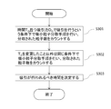
- Particle number counting step S301 Particle count process of FIG. 6 S301, the microparticles suction flow predetermined suction force suction by path D 0 at the time when the predetermined time T 0 has elapsed since the fine particles have passed through the predetermined position of the main flow path It is performed under the condition that it is performed at. Under this condition, a microparticle sorting procedure is executed in the microchip, and the number of microparticles sucked into the microparticle suction channel as a result of executing the sorting procedure is counted.
- a time point at which the fine particles pass is detected at a predetermined position of the main flow path through which the liquid containing the fine particles flows.
- the predetermined position on the main flow path may be a position where the passage of fine particles can be detected.
- the predetermined position may be, for example, in a detection region on the main channel, and is, for example, a light irradiation position.
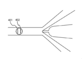
- FIG. 7 is an enlarged view of the sorting unit 107.
- two light beams 401 and 402 are irradiated in the detection region perpendicular to the traveling direction of the particles.
- the irradiation interval between the two lights 401 and 402 is, for example, 20 to 200 ⁇ m, preferably 30 to 150 ⁇ m, and more preferably 40 to 120 ⁇ m.
- the wavelengths of these two lights may be different or the same.
- the predetermined position may be, for example, the irradiation position of the light 402 on the microparticle suction channel side of the two lights, or may be the irradiation position of the other light 401.
- microparticles are sucked from the main channel into the microparticle suction channel with a predetermined suction force by the microparticle suction channel.
- the suction is performed when a predetermined time T 0 has elapsed from when the predetermined position is passed.
- the predetermined time T 0 from when the predetermined position is passed may be appropriately set by those skilled in the art.
- the size of the microchip in particular, from the light irradiation region on the main flow path of the microchip to the entrance of the orifice portion. And / or the flow rate of the particles.
- the distance can be, for example, the distance from the light irradiation position on the fine particle suction flow channel side to the entrance of the orifice portion among the two lights.
- the distance is, for example, 300 ⁇ m to 1500 ⁇ m.
- the time T 0 reaches any position in the region where the microparticles are sucked into the microparticle suction channel when the suction is performed with the suction force D 0 from the time when the predetermined position is passed. It is the time to the point. Alternatively, it may be the time from the time when the predetermined position is passed to the time before reaching the area.
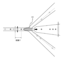
- FIG. 8 is an enlarged view of the sorting unit 107.
- a region 501 that extends in an elliptical shape from the entrance of the microparticle suction channel toward the irradiation region is sucked by the suction force D 0 , the microparticles are sucked into the microparticle suction channel. It is an area.
- the time from passing through the light irradiation position to the point where advanced particles the distance Y may be adopted as the time T 0.
- the time T elapses the particles reach the region.
- the time from passing through the light irradiation position to the point where particles reach in any position within this area may be adopted as the time T 0.
- the velocity of the particles in the flow path can be taken into account as needed.
- the speed is appropriately measured by a method known to those skilled in the art. For example, as shown in FIG. 7, when two light irradiation positions 401 and 402 are provided, it took a distance between the two irradiation positions and the passage between the two irradiation positions. Based on the time, the velocity of the particles in the flow path is calculated. By such a calculation method, the velocity of the particles can be calculated with higher accuracy. In addition, the suction conditions are better optimized by calculating the particle velocity with high accuracy.
- the distance from the predetermined position is calculated from the speed and the elapsed time.
- the distance Y from the predetermined position may be used as a variable. That is, in another embodiment of the present technology, the microparticles when in a particle counting step, microparticles progressed toward the fine particle suction flow path from a predetermined position by a predetermined distance Y 0 of the main road Under the condition that suction by the suction channel is performed at a predetermined suction force D 0 , a microparticle sorting procedure is executed in the microchip, and as a result of executing the sorting procedure, suction is performed in the microparticle suction channel. The number of microparticles taken is counted.
- the distance from the predetermined position at which suction by the microparticle suction channel is to be performed is determined. That is, in the present technology, the distance from the predetermined position where the suction should be performed is optimized instead of the timing when the suction should be performed. That is, instead of the time T, the distance Y from the predetermined position may be used as a variable.
- the suction by the fine particle suction flow path with the predetermined suction force D 0 is performed, for example, by making the inside of the fine particle suction flow path have a negative pressure.
- the negative pressure is set by an actuator such as a piezo element. Since between the driving voltage of the suction force D 0 and the piezoelectric element there is a predetermined relationship, by adjusting the driving voltage of the piezoelectric element, the suction force D 0 can be adjusted. Adjustment of the driving voltage of the piezo element may be performed by means known to those skilled in the art.
- the microparticle sorting procedure is, for example, the above-described 1. This can be carried out using the microparticle sorting apparatus equipped with the microchip described in the above. Refer to the specification of Japanese Patent Application No. 2017-102694 for details of the configuration of the microparticle sorting apparatus.
- a sample liquid containing a known number of microparticles can be used.
- the number of fine particles may be appropriately set by those skilled in the art, and is, for example, 10 to 1000, particularly 30 to 500, and more particularly 50 to 300.
- a sample liquid containing a known number of microparticles is introduced from the sample liquid inlet 101 and proceeds through the sample liquid flow path 102, and the sheath liquid is introduced from the sheath liquid inlet 103. And proceed through the sheath fluid flow path 104.
- the sample liquid and the sheath liquid merge to form a laminar flow, and the laminar flow flows through the main channel 105 toward the sorting unit 107.
- the laminar flow is irradiated with light in the detection region 106. As the microparticles pass through the detection region, scattered light and / or fluorescence is generated from the microparticles.
- suction with the suction force D 0 is performed when the predetermined time T 0 has passed since the minute particle passed through the predetermined position. For example, in a microparticle sorting procedure using a sample liquid containing 100 microparticles, suction is performed for each microparticle, that is, suction is performed 100 times.
- the number of fine particles sucked into the fine particle suction channel is counted.
- the number of microparticles sucked into the microparticle suction channel as a result of performing the microparticle sorting procedure on a known number of microparticles is counted.
- the counting may be performed by means known to those skilled in the art, or may be performed in a detection region provided in the microparticle suction channel.
- Counting the number of the fine particles can be performed at a predetermined position in the fine particle suction channel. For example, the number of microparticles is counted by detecting passage of a predetermined position in the microparticle suction channel.
- An example of the detection region provided in the fine particle suction channel is, for example, a light irradiation region 202 shown in FIG. As shown in FIG. 2, when the microparticles pass through the light irradiation region 202 provided in the microparticle suction channel, scattered light and / or fluorescence is emitted from the microparticles. By detecting the scattered light and / or fluorescence, the number of microparticles sucked into the microparticle suction channel is counted.
- the fine particles may be appropriately selected by those skilled in the art.
- the microparticles may include biological microparticles such as cells, microorganisms, and liposomes, and synthetic particles such as latex particles, gel particles, and industrial particles.
- biological microparticles such as cells, microorganisms, and liposomes
- synthetic particles such as latex particles, gel particles, and industrial particles.
- synthetic particles particularly beads for optimizing suction conditions are used as the microparticles, and in the present technology, they can be used as the adjusting microparticles.
- Such synthetic particles are more preferred for the method of the present technology because they are more readily available than biological microparticles.
- the biological microparticles include chromosomes, liposomes, mitochondria, organelles (organelles) that constitute various cells.
- the cells include animal cells (such as blood cells) and plant cells.
- the microorganism examples include bacteria such as Escherichia coli, viruses such as tobacco mosaic virus, and fungi such as yeast.
- the biological microparticles also include biological macromolecules such as nucleic acids, proteins, and complexes thereof.
- the synthetic particles may be particles made of, for example, an organic or inorganic polymer material or metal.
- the organic polymer material examples include polystyrene, styrene / divinylbenzene, and polymethyl methacrylate.
- the inorganic polymer material examples include glass, silica, and a magnetic material.
- the metal include gold colloid and aluminum.
- the shape of the microparticles may be generally spherical or substantially spherical, or may be non-spherical.
- the size and mass of the microparticles are appropriately selected by those skilled in the art depending on the size of the microchip channel.
- the size of the channel of the microchip is appropriately selected depending on the size and mass of the microparticles.
- the microparticle can be attached with a chemical or biological label, such as a fluorescent dye, as necessary.
- the label makes it easier to detect the microparticles.
- the label to be attached can be appropriately selected by those skilled in the art.
- the microchip used in the method of the present technology is manufactured by a method known in the art.
- the microchip used in the method of the present technology is, for example, the above described 1-1. It can be manufactured by bonding two substrates on which a flow path as described in the microchip for sorting microparticles is formed.
- the flow path may be formed on both of the two substrates, or may be formed only on one of the substrates. In order to more easily adjust the position at the time of bonding the substrates, the flow path can be formed only on one of the substrates.
- a material for forming a microchip used in the present technology a material known in the art can be used. Examples include, but are not limited to, polycarbonate, cycloolefin polymer, polypropylene, PDMS (polydimethylsiloxane), polymethyl methacrylate (PMMA), polyethylene, polystyrene, glass, and silicon.
- polymer materials such as polycarbonate, cycloolefin polymer, and polypropylene are particularly preferable because they are excellent in processability and can be manufactured at low cost using a molding apparatus.
- Step S302 for repeating the particle number counting step the particle number counting step is repeated while changing the time from when the fine particles pass through a predetermined position of the main channel to when the suction is performed.
- the particle number counting process is repeated in the same way except that the T 0 is changed to a longer and / or shorter various times T n .
- the time T n is appropriately set by those skilled in the art in consideration of, for example, the size of the microchip, a region where the suction force reaches when a predetermined suction force is applied, and / or tolerance.
- step S302 to repeat that particle count step for each of the various time T n is made, the particle count results for each of the various time T n is obtained.
- the various times T n may be the respective times when the T 0 is increased and / or decreased stepwise at a predetermined rate.
- the predetermined ratio is, for example, 0.01% to 5%, particularly 0.05 to 2%, more particularly 0.1 to 1%.
- the number of steps for increasing and / or decreasing T 0 is, for example, 5 to 50 steps, particularly 7 to 40 steps, and more particularly 10 to 30 steps.
- the various times T n are (T 0 + T 0 ⁇ 0.2%), (T 0 + T 0 ⁇ 0.2% ⁇ 2), (T 0 + T 0 ⁇ 0.2% ⁇ 3),..., And (T 0 + T 0 ⁇ 0.2% ⁇ 20), and (T 0 ⁇ T 0 ⁇ 0.2%), (T 0 ⁇ T 0 ⁇ 0.2% ⁇ 2), (T 0 ⁇ T 0 ⁇ 0.2% ⁇ 3),..., And (T 0 ⁇ T 0 ⁇ 0.2% ⁇ 20).
- the T 0 including, at each elapsed time of 41 (1 + 20 + 20) in total, the procedure microparticle sorting may be performed.
- the number of steps for increasing T 0 and the number of steps for decreasing T 0 may be the same or different. Further, the various times T n may be only those obtained by increasing the T 0 , or may be only those obtained by decreasing the T 0 . The number of steps for increasing T 0 and the number of steps for decreasing T 0 may be appropriately set by those skilled in the art. Also, for each of the various time T n, a plurality of times the particle count process, for example 2-5 times, may be particularly carried out 2-3 times.
- step S302 Particle count process performed in step S302 to repeat above, except for changing the T 0 longer and / or more short various time T n is the same. Therefore, for the description of the particle number counting step, see (1) above.
- Step S303 for determining the time during which suction should be performed the fine particle suction is performed based on the number of fine particles counted in the particle number counting step S301 or in the particle number counting step S301 and the repeating step S302.
- the elapsed time from when the predetermined position is to be sucked by the flow path is determined.
- the determination is automatically performed by a control unit that executes a predetermined program.
- the time T when the number of fine particles counted in the particle number counting step S301 and the repeating step S302 is the largest is determined as the elapsed time for the suction.
- an arbitrary time out of the plurality of times may be determined as the elapsed time during which the suction should be performed, or the plurality of times
- a central value of the time may be determined as an elapsed time during which the suction should be performed.
- FIG. 5 is a schematic diagram showing a situation in the flow channel when the fine particle sorting procedure is performed.
- a region 601 that expands in an elliptical shape from the entrance of the microparticle suction channel toward the irradiation region is sucked with the suction force D 0 , the microparticles are sucked into the microparticle suction channel. It is an area.
- the predetermined position is a position farther from the fine particle suction flow path among the two light irradiation positions.
- the fine particle 602 that has passed through the predetermined position advances by a distance Y 0 from the predetermined position when the predetermined time T 0 has elapsed, and is at the position shown in FIG.
- the microparticles 602 are within region 601 Therefore, it is sucked into the fine particle suction channel. As shown in FIG.
- the minute particles are theoretically in the region 601 when the predetermined time T 0 has elapsed after the minute particles have passed the predetermined position. However, it may not be sucked into the microparticle suction channel due to factors such as the state of the laminar flow being formed, the shape of the particles, and / or the actual suction force.
- the microparticles when performing suction in T i with increased time T 0, the microparticles are in the position 603, for example. Even if the suction is performed with the suction force D 0 in the position 603, the fine particles are not drawn into the fine particle suction flow path because they are outside the region 601. In FIG. 9, when the suction is performed at T j where the time T 0 is decreased, the fine particles are at the position 604, for example. Even if the suction is performed at the position 604 with the suction force D 0 , the fine particles are not drawn into the fine particle suction flow path because they are outside the region 601. Note that, as shown in FIG.
- the minute particles are theoretically outside the region 601 when the time T i or T j elapses after the minute particles pass the predetermined position. However, it may be sucked into the microparticle suction channel due to factors such as the state of the laminar flow being formed, the shape of the particles, and / or the actual suction force.
- a graph in which the T 0 is changed to various times and the number of particles counted at each time is plotted against time is shown on the right side of FIG. As shown in the graph, the number of particles counted is the largest when the elapsed time is within a predetermined range.
- An arbitrary time within the predetermined range may be determined as an elapsed time for the suction to be performed, or a central value within the predetermined range is determined as an elapsed time for the suction to be performed. Also good.
- a success rate of suction of the microparticles into the suction flow path is calculated based on the number of microparticles counted in the particle number counting step and the repetition step, and based on the success rate
- the elapsed time from when it passes through the predetermined position to be suctioned by the fine particle suction channel is determined.
- the elapsed time when the success rate is the highest may be determined as the elapsed time from when the predetermined position is passed through which the suction by the fine particle suction flow path should be performed.
- an arbitrary time may be determined as an elapsed time during which the suction should be performed from among a plurality of elapsed times in which the success rate is equal to or greater than a predetermined value, or of the plurality of elapsed times
- the median value may be determined as the elapsed time during which the suction should be performed.
- the method for optimizing the suction conditions of the microparticles of the present technology may further include a second repetition step in which the suction force is changed and the particle number counting step and / or the repetition step is repeated.
- the optimization method of the present technology includes the second repeating step, in the determining step, the number of microparticles counted in the particle number counting step and / or the repeating step and the second repeating step Based on the above, the elapsed time from when the microparticles pass through the predetermined position and the suction force to be applied to the suction of the microparticles to be suctioned by the microparticle suction channel are determined.
- steps S401 and S402 are the same as in 2-1. This is the same as steps S301 and S302 described in the basic suction condition optimization method I. Therefore, the description about these processes is omitted.
- Second repetition step S403 of repeating the particle number counting step In the second repeat step S403 in FIG. 10, except for changing the suction force D 0 to larger and / or smaller various suction force D n in the same way, repeated the particle count step and / or said The process is repeated.
- the second repeat step S403 in FIG. 10 except for changing the suction force D 0 to less various suction force D n in the same way is repeated particle count step S401 and repeats step S402 .
- the suction force D n considers factors such as the specifications of the suction means provided in the fine particle suction flow path, the size of the microchip, the area where the suction force reaches when a predetermined suction force is applied, and / or tolerances. Thus, it is appropriately set by those skilled in the art.
- step S403 to repeat that the particle count process is performed for each of the various suction force D n, particle count results for each of the various suction force D n is obtained.
- the various suction forces D n are the suction forces obtained by increasing or decreasing the D 0 stepwise at a predetermined rate.
- the predetermined proportion can be, for example, 0.01-30%, in particular 0.1% -25%, more particularly 1-20%, even more particularly 1-10%.
- the number of steps for increasing or decreasing D 0 is, for example, 3 to 20 steps, particularly 4 to 15 steps, more particularly 5 to 10 steps.
- the various suction forces D n are (D 0 -D 0 ⁇ 20%), (D 0 -D 0 ⁇ 20% ⁇ 2), (D 0 -D 0 ⁇ 20% ⁇ 3), and (T 0 -T 0 ⁇ 20% ⁇ 4).
- the D 0 including, in each of the five attraction in total, the procedure microparticle sorting is performed.
- the number of steps for increasing D 0 and the number of steps for decreasing D 0 may be the same or different.
- the various suction forces D n may be only those obtained by increasing the D 0 , or may be only those obtained by decreasing the D 0 .
- the number of steps to reduce the number and the D 0 stage to increase the D 0 may be appropriately set by the value of the D 0.
- the particle number counting step may be performed a plurality of times, for example, 2 to 5 times, particularly 2 to 3 times.
- Step S404 of determining the time at which suction is to be performed and / or the suction force to be applied In step S404 for determining the time for suctioning and / or the suction force to be applied in FIG. 10, the number of microparticles counted in the particle number counting step S401, the repeating step S402, and the second repeating step S403. Based on the above, the elapsed time from when the predetermined position is passed and / or the suction force to be applied to the suction of the microparticles to be suctioned by the microparticle suction flow path are determined. As a result, the time point at which the microparticles are to be suctioned and the suction force to be applied are optimized. The determination is automatically performed by, for example, a control unit that executes a predetermined program.
- the determining step S404 for example, the time T and the suction force D when the number of fine particles counted in the particle number counting step S401, the repetition step S402, and the second repetition step S403 are the largest and the suction force is the smallest are obtained. , The elapsed time at which the suction should be performed and the suction force to be applied.
- the suction force D that minimizes the suction force is determined as the suction force to be applied from the combination of the time T n and the suction force D n when a predetermined number or more of fine particles are counted, and A central value among a plurality of elapsed times in which fine particles are counted by a predetermined number or more with the determined suction force may be determined as an elapsed time for which suction is to be performed.
- the suction is performed for any combination of time and suction force from among these combinations.
- the minimum value of the suction force is determined as the suction force to be applied, and A central value among a plurality of times may be determined as an elapsed time during which the suction is to be performed.
- FIG. 9 is a schematic diagram showing a situation in the flow channel when the fine particle sorting procedure is performed as described above.
- the micro particles 602 are: In the region 601, it is sucked into the fine particle suction channel.
- FIG. 11 shows that when the predetermined time T 0 or T 1 has passed since the minute particles passed through the predetermined position on the main channel, the suction by the minute particle suction channel is smaller than the suction force D 0. under the condition that performed by the force D n, it is a schematic diagram showing the status of the flow path when doing the procedure microparticle sorting.
- region 801 extends into an elliptical shape from the entrance of the fine particle suction channel towards the irradiation area, fine particles are attracted to the fine particle suction passage to aspiration by suction force D n It is an area.
- the predetermined position is a position farther from the fine particle suction flow path among the two light irradiation positions.
- the minute particles 802 that have passed through the predetermined position are moved by the distance Y 0 from the predetermined position when the predetermined time T 0 has elapsed, and are at the position shown in FIG.
- the microparticles 802 are in the region 601, so Inhaled.
- the microparticles 802 are outside the region 801, so that the microparticle suction flow It is not sucked into the street.
- the minute particles 803 that have passed through the predetermined position are moved by the distance Y 1 from the predetermined position when the predetermined time T 1 elapses, and are at the position shown in FIG.
- the microparticles 803 are within region 801 Therefore, it is sucked into the fine particle suction channel.
- the smaller the suction force the narrower the region where the suction force reaches.
- the success rate of suction of the microparticles into the suction channel is based on the number of microparticles counted in the particle number counting step, the repetition step, and the second repetition step. Based on the calculated success rate, an elapsed time from when passing through the predetermined position and / or a suction force to be applied to be suctioned by the fine particle suction flow path is determined. For example, the time T and the suction force D when the success rate is the highest and the suction force is the smallest are determined as the elapsed time during which the suction should be performed and the suction force to be applied.
- the time T and the suction force D at which the suction force is minimized are used as the elapsed time and application for which the suction is performed. It may be determined as a suction force to be performed.
- any combination of time and suction force is selected from the combinations. It may be determined as the elapsed time to be performed and the suction force to be applied.
- the minimum of the suction force is determined as the suction force to be applied, and A central value among a plurality of times may be determined as an elapsed time during which the suction is to be performed.
- the suction force is stepwise reduced at a predetermined ratio from the suction force D 0, and the second The repeating step 2 can be performed until a result is obtained in which the number of microparticles sucked into the microparticle suction channel becomes zero at any elapsed time.
- the suction force increased at a predetermined rate from the suction force when a result of 0 is obtained at any elapsed time is applied to the suction of the microparticles. It can be determined as the power of attraction.
- the suction force can be automatically optimized. Status changes in the flow path when the suction force was reduced from the suction force D 0 is as described above with reference to FIGS. 9 and 11.
- the predetermined ratio and the number of stages of reduction are as described in (1) above.
- the situation in the channel will be described below with reference to FIG. 12 in the case where a result is obtained in which the number of microparticles sucked into the microparticle suction channel is zero at any elapsed time.
- the solid line and the dotted line in the flow path indicate the positions through which the fine particles pass.
- a region 901 from the entrance of the fine particle suction channel are slightly spread toward the illuminated region, the suction force microparticles suction passage to aspiration in smaller attraction force D Z than D 1 This is a region where fine particles are sucked.
- the region 901 does not overlap with either the solid line or the dotted line indicating the position through which the microparticles pass.
- a graph in which the T 0 is changed to various times and the number of particles counted at each time is plotted against time is shown on the right side of FIG. As shown in the graph, the count number is 0 regardless of the elapsed time.
- the second repetition step is performed until a result is obtained that the number of microparticles sucked into the microparticle suction flow path becomes zero at any elapsed time. That is, the second repetitive step is terminated when a result is obtained that the number of microparticles sucked into the microparticle suction flow path becomes zero at any elapsed time.
- a suction force increased at a predetermined rate from the suction force when a result of 0 is obtained in any of the elapsed times should be applied to the suction of the microparticles. Determined as suction force.
- the suction force that is increased from the suction force when a result of 0 is obtained at any elapsed time is determined as the suction force to be applied to the suction of the microparticles is determined by the second method.
- D 0 when D 0 is decreased by 1 to 10%, from the suction force that results in 0 at any elapsed time, for example, (the reduction ratio (ie, 1 to 10%) ⁇ 1) to A value obtained by adding the value of (the reduction ratio ⁇ 5) to the suction force that obtained a result of 0 in any elapsed time is determined as the suction force to be applied.
- the reduction ratio ie, 1 to 10%
- the sample core is carried out in a very small state with respect to the sheath flow. That is, it is assumed that the velocity of the microparticles flowing inside the sample core is constant, and suction is performed so as to obtain an optimal microparticle fractionation timing and a fractional suction amount (actuator driving force) of the microparticle-containing sample liquid. Yes. In this way, if there is no difference in velocity between the microparticles in the sample core, it is possible to automatically calculate the best sorting timing for the velocity of the microparticles even if the velocity of the sheath flow changes. It has become.
- the concentration adjustment of the microparticle-containing sample liquid is generally performed as a pretreatment for setting the microparticle-containing sample liquid in the microparticle sorting apparatus described later, so the concentration adjustment is performed while the apparatus is processing. Without adjustment, the number of microparticles passing in one second (hereinafter, also referred to as “sample event rate”) is adjusted by the amount of the sample solution fed.
- the size of the sample core in the main flow path of the microchip for sorting microparticles is determined by the volume of the sample liquid containing the microparticles, and even when the sample liquid has a low microparticle concentration, the sample event rate is increased. For this, it is necessary to increase the amount of the microparticle-containing sample liquid, and the size of the sample core also increases.
- FIG. 13 shows a case where the flow rate of the microparticle-containing sample liquid is small and the sample core size is small
- FIG. 14 shows a case where the flow rate of the microparticle-containing sample liquid is large and the sample core size is large.
- Fine particle fractionation is a method of sucking particles by operating a pressure chamber and generating minute negative pressure, so if the sample core size increases, the sample suction port located at the center of the main channel A large amount of particles that pass through a position far from the center of the sample core cannot be stably suctioned with a preparative suction amount (driving force of the actuator) when the sample core size is small. In such a situation, it is impossible to achieve good sorting performance if the sorting suction amount remains fixed, and optimum control of the suction amount adapted to the passing position of the fine particles is required. Therefore, this technology has developed the following suction condition optimization method.
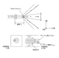
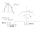
- each microparticle is twice as fast as the average flow velocity, but when the sample core size is large, the area through which the microparticles pass through the main channel is also large, so the microparticle velocity Diffuses and the microparticle velocity decreases in inverse proportion to the distance from the center of the main channel.
- V individual velocity of a group of microparticles at a certain time (for example, 1 second)
- V ave average velocity of the group of microparticles
- V max the fastest of the individual microparticles in the group of microparticles
- V min Individual microparticle velocity that is the lowest among the individual microparticles in the group of microparticles.
- the fixed time is a fractionated from a predetermined position of the main channel. It can be set as the time for the microparticles to pass to the position where they do. This time can be set as time t.
- V ave For example, by normalizing (V / V ave ) individual microparticle velocities using the average flow velocity: V ave , it is possible to use it as an index indicating the distance from the center of the main channel. In doing so, the individual V / V ave is calculated using the data of velocity V of as many individual microparticles as possible, preferably the data of the velocity V of all the microparticles that pass almost in the vicinity of the center of the flow path. Is preferred. Thereby, a more suitable approximate value of the center flow velocity of the sample core can be obtained. In addition, even if turbulent flow due to the microparticle microchip or pulsating flow due to actuator drive occurs, the center flow velocity of the sample core can be grasped more accurately than before. .
- the distance from the suction port (microchip for sorting microparticles of the present technology) shown in FIG. 15 is Z (fixed value) in the flow direction, and X is the distance from the center as described above.
- the Y corresponds to the velocity V of each individual microparticle, so if the velocity V of each individual microparticle is substituted into the above equation 4, a desired suction force, that is, a desired actuator drive. Force can be calculated.
- V / V ave is used in the present technology, since the measured speed of the individual microparticles is normalized by the V ave as described above, the same coefficient can be used regardless of the speed.
- the driving force of the actuator at the time of suction is controlled to be inversely proportional to V / V ave based on the V / V ave , the fine particles (velocity V max ) at the center of the sample core are separated from the center of the sample core with a small driving force.
- the particles (velocity V min ) can be sucked with a large driving force, and the sorting suction force adapted to the particle position from the sorting suction port can be individually controlled.
- a step of controlling the driving of the actuator in inverse proportion to the index calculated by V / V ave may be included as the average velocity V ave of the microparticles in the predetermined time.
- the fine particles when flowing through the substantially central portion of the fine particle-containing sample solution, the maximum velocity V max in fine particles in the fixed time, the driving of the actuator in said V max is V ave If the pressure is made smaller than before and the pressure in the pressure chamber is increased, the suction force acting on the fine particles is lowered. Using V / V max as an index, the pressure is controlled to be inversely proportional.
- the fine particles when flowing through the substantially outermost fine particle-containing sample solution, said a minimum speed V min in the microparticles at a fixed time, the actuator of the driven V ave at the V ave If the pressure in the pressure chamber is reduced and the pressure in the pressure chamber is reduced, the suction force acting on the fine particles increases.
- the maximum flow rate can be maintained by increasing the flow rate of the sample liquid even when the microparticle concentration is low. And deterioration of sorting performance can be suppressed.
- concentration treatment a small amount of fine particles to be collected is low, but a large amount of fine particles are processed
- a purification treatment that prioritizes purity in order to make the purity of particles to be collected very high Even in the sorting state in which the size of the sample core is large, it is possible to maintain good fine particle sorting characteristics.
- Embodiment of Fine Particle Suction Control> As one embodiment of the present technology, for example, In a microchip for sorting microparticles, including a main channel through which a sheath liquid and a microparticle-containing sample liquid flow, and a pressure chamber that sucks microparticles by driving an actuator, The sheath liquid and the adjustment microparticle-containing sample liquid are allowed to flow through the main channel, and the time when the adjustment microparticles pass at a predetermined position of the main channel is detected, and the velocity V data of the adjustment microparticles is obtained.
- Process to acquire A step of sucking the fine particles for adjustment from the main flow path to the pressure chamber with a predetermined suction force; A particle number counting step for counting the number of fine particles for adjustment sucked into the pressure chamber, and a time from when the fine particle for adjustment passes a predetermined position of the main flow path until the suction is performed, A step of determining an elapsed time from when the predetermined position is passed, based on the counted number of adjustment microparticles; A larger amount of the sample liquid than the adjustment microparticle-containing sample liquid is passed through the main channel, and the time when the adjustment microparticles pass at a predetermined position of the main channel is detected to detect the individual adjustment microparticles.
- a method of controlling the pressure in the pressure chamber in inverse proportion to the index calculated by V / V ave , and performing the fractionation of the fine particles for adjustment into the pressure chamber. can be optimized.
- the timing at which suction is performed by incorporating the velocity data acquisition step of the fine particles and the drive control step of the actuator that controls the pressure of the pressure chamber, and / or The magnitude of the applied suction force is further optimized, and the sorting performance of the fine particles can be further enhanced.
- the fine particle velocity data acquisition step and the actuator drive control step may be incorporated into the sorting means in step S301 and / or the sorting procedure in step S302.
- the actuator drive is increased and / or decreased, and the number of particle counts of the already adjusted fine particles is approximately the same as the total number of the adjusted fine particles. It may include calculating a constant.
- microparticle velocity data acquisition step and actuator drive control step may be incorporated. Referring to FIG. 10, if any of the steps S401, S402, and S403, or a combination of the steps, or a fractionation procedure in all steps, the velocity data acquisition step of microparticles and the drive control step of the actuator are incorporated. Good.
- steps S301 to S303 in FIG. 6 are first performed, and then the velocity data acquisition step of the microparticles and the actuator are performed in one of the steps S401, S402, and S403 in FIG. Steps S401 to S403 incorporating a drive control step may be performed, and finally step S404 may be performed.
- steps S301 to S303 in FIG. 6 are first performed, then steps S401 to S404 in FIG. 10 are performed, and any one of steps S301, S302, S401, S402, and S403, or an appropriate combination thereof is performed.
- Embodiment I As a specific example, an example of the adjustment procedure of the method for optimizing the suction conditions for the fine particles of the present technology will be described.
- the driving force and operation of the actuator related to the pressure chamber of the microchip for microparticle sorting in the method for optimizing microparticle suction according to the present technology for example, it is possible to detect scattered light by light irradiation. Microbeads are used as the fine particles for adjustment. Then, based on the information on the behavior of the adjustment microbeads obtained from the scattered light, the fine particle sorting timing T and the suction force D are optimized in the following adjustment procedures 1 to 15. A piezoelectric element was used as the actuator.
- Adjustment procedure 1 Set the microparticle sorting microchip and the adjustment microbead in the microparticle sorting device, send the sheath liquid, and start the automatic adjustment program.
- Adjustment procedure 2 After degassing the microparticle sorting tip and the microchannel of the microparticle sorting device with the sheath liquid, the microbeads for adjustment are flowed (the sample core size is kept very small). The position of the chip is adjusted (X axis, Y axis, Z axis) so that the signal intensity (scattered light or fluorescent signal) from the particles is maximized.
- Adjustment procedure 3 Scattered signals at the laser detection unit and the post-sorting detection unit are acquired by the optical system shown in FIG. 5, and the time difference (passed from a predetermined position in the main flow path) that passes through the two spots of the laser sorting unit.
- the individual particle velocity: V is calculated from the time t) when the microparticles pass to the position to be taken.
- Adjustment Procedure 6 actuator driving force: D 1 remains fixed, the distance: Y while changing the swept allowed prep time, and detects a preparative spent grain at that time to obtain a count number distributions.
- Adjustment procedure 7 Actuator driving force: D 2 in which the fractionation suction amount is made smaller than that in the adjustment procedure 5. The same detection operation as that in the adjustment procedure 6 is performed at D 2 , and the optimum sorting distance Y 2 (sorting time) is recorded. .
- Actuator driving force has a small amount of suction intake adjustment procedure 8 minutes: at D 2, performs the same detection operation and adjustment procedure 6, record the optimum preparative distance Y 2 (prep time).
- Actuator driving force count becomes zero adjustment procedure 10 prep spent grain: large or should than D 3 actuator driving force: D 2 and preparative distance Y 2 a (prep time) as the optimal preparative parameters Adopt and conduct sorting operations.
- Adjustment procedure 11 The adjustment beads, which are several times (for example, 10 times) the amount of sample supplied in adjustment procedure 2, are sent, and the optical signals shown in FIG. And the individual particle velocity: V is calculated from the time difference between the two spots of the laser sorting unit.
- V ave An average particle velocity (for example, 1 second) for a certain period of time is defined as V ave, and this particle velocity: V is divided by V ave to obtain a coefficient that is inversely proportional to the particle position from the center of the sample core.
- Adjustment procedure 14 If the number of times of fractionation and the count of the fractionated particles are almost 100% under the above conditions, the adjustment is completed. If 100% is not reached, the value of K is searched for ⁇ . Obtain a distribution of pre-sorted particle counts.
- Adjustment procedure 15 The K value of the center value of the distribution in which the pre-sorted particle count is close to 100% or has obtained 100% is adopted as the preparative condition.
- Adjustment procedure 16 Stops the sample feeding, cleans the flow path through which the sample flows with the sheath liquid and other flow paths, and ends the automatic adjustment.
- the optimal fractionation timing: T and the suction amount: D are adjusted to sort the microparticles to be collected. be able to. Furthermore, even when the sample core is large and the microparticle position in the main flow path of the microchip for sorting microparticles is different, the suction force can be automatically controlled to the optimum suction amount suitable for the microparticle position. Even if the amount of sample liquid fed increases or decreases, it is possible to maintain good sorting performance. Therefore, a state with high robustness can be maintained even in a microparticle sorting system described later.
- Embodiment II As a more specific example, it is possible to optimize the suction conditions for the fine particles of the present technology according to the flowchart shown in FIG. Hereinafter, each process of FIG. 16 will be described. A piezoelectric element was used as the actuator.
- Process 1 Set conditions for feeding sheath liquid and microparticle-containing sample liquid to a microparticle sorting apparatus equipped with the program described below.
- This liquid feeding condition can be defined in advance so that the size of the sample core is minimized.
- Process 2 Place the microchip for sorting microparticles and the microbead for adjustment in the microparticle sorting machine.
- Process 3 The automatic adjustment parameters for optimizing the fine particle suction conditions incorporated in the program in advance are reset as necessary.
- Process 4 On the user interface (eg, GUI) such as a touch panel, click the automatic adjustment start button of the microparticle sorting device.
- GUI graphical user interface
- Process 5 Sends sheath fluid and starts an automatic adjustment program. With the sheath liquid, the flow path of the set microparticle sorting microchip is degassed.
- Process 6 The sample loader for supplying the microparticle-containing sample liquid provided in the microparticle sorting apparatus is brought into a pressurized state, and the liquid supply of the adjusting beads is started.
- Process 7 Wait until the delivery of the sample liquid containing fine particles is stabilized. For example, it may be programmed to wait for one minute in advance. Then, the position adjustment (X axis, Y axis, Z axis) of the microchip for sorting microparticles is performed so that the signal intensity of scattered light or fluorescence from the microparticles is maximized.
- Process 9 Sorting operation timing calculated in Process 8: Actuator is driven at T.
- Process 10 The microbeads for adjustment collected are detected by, for example, a scattered light detection system, and the number of fractions is measured.
- Process 12 Based on the data obtained by repeating the process 9 to the process 11 20 times, for example, a sorting timing T at which the number of the adjusted microbeads is the maximum or the center of the maximum value is adopted. .
- the suction force by the driving of the actuator gradually reducing the suction force from D 0, for example D 0 5% discount is carried out by preparative operation in 95% of the suction force that time adjustment that is dispensed into
- the number of microbeads for use is counted by the detection unit after sorting, and the search is continued until the count after sorting becomes zero. Note that the process 9 to the process 13 may be repeated.
- Process 14 When the counter reaches 0 after sorting, that is, search to the limit of the suction force at which suction cannot be performed, the actuator drive voltage two steps before (process 12), ie suction force: D, sorting timing: T is optimal. Adopt as a value.
- Process 15 increase the flow rate of the sample liquid containing fine particles and increase the size of the sample core.
- a coefficient proportional to the microparticle position is set to K, and a coefficient K is applied to the actuator driving voltage (D 2 ⁇ (V / V ave )).
- Process 17 Count the number of preparative microbeads dispensed. Steps 16 and 17 may be repeated until all the adjustment microbeads are acquired. The above processes 15 to 17 are the suction amount correction sequence.
- Process 18 When all the adjustment microbeads have been acquired, the feeding of the microparticle-containing sample liquid is stopped, and the backflow cleaning of the line through which the microparticle-containing sample liquid has flowed is performed. This completes the automatic adjustment sequence.
- Microparticle sorting program> The present technology also provides a fine particle sorting program for causing a computer to realize a function of controlling the fine particle sorting device in order to perform the method for optimizing the suction conditions of the fine particles.
- the fine particle sorting program of this technology is (A) Using a microchip for sorting microparticles, including a main channel through which a sheath liquid and microparticle-containing sample liquid flow, and a pressure chamber for sucking microparticles, Passing the sheath liquid and the microparticle-containing sample liquid through the main channel, detecting the time when the microparticles pass at a predetermined position of the main channel, and acquiring the data of the velocity V of each microparticle; And (F) acquiring data of the average velocity V ave of the microparticles for a certain time, and causing the computer to control the suction force of the pressure chamber in inverse proportion to the index calculated by V / V ave It is a program.
- the program is between (A) and (F), (B) sucking the adjustment microparticles from the main flow path into the pressure chamber with a predetermined suction force; (C) counting the number of the adjustment microparticles sucked into the pressure chamber; D) Based on the time from when the fine particles for adjustment pass through a predetermined position of the main flow channel until the suction is performed and the counted number of fine particles for adjustment, Determining the elapsed time from when the predetermined position is to be sucked, and (E) passing a larger amount of sample liquid than the adjustment microparticle-containing sample liquid through the main channel, Detecting the time point at which the fine particles for adjustment pass at a predetermined position of the main flow path, and acquiring the data of the velocity V of each fine particle for adjustment; May be a program that causes a computer to execute.
- the program may be stored in a recording medium such as a magnetic disk, an optical disk, a magneto-optical disk, or a flash memory, and may be distributed via a network.
- a recording medium such as a magnetic disk, an optical disk, a magneto-optical disk, or a flash memory
- the program can externally perform analysis with a computer attached to the microparticle sorting apparatus, or can be built into the microparticle sorting apparatus and execute analysis. .
- Microparticle sorting system The present technology also provides a system for sorting microparticles that can perform the method for optimizing the suction conditions of the microparticles.
- the system for sorting fine particles A microchip for sorting microparticles, including a main channel through which the sheath liquid and the microparticle-containing sample liquid flow, and a pressure chamber for sucking the microparticles; Velocity data for acquiring the data of velocity V of individual microparticles by passing the sheath liquid and the microparticle-containing sample liquid through the main channel and detecting the time when the microparticles pass at a predetermined position of the main channel.
- An acquisition device A pressure control device for controlling the pressure for sucking the microparticles based on the data of the velocity V of the individual microparticles; It includes a computer in which a program for controlling the pressure is incorporated.
- a computer for example, a computer in which the programs (A) and (F) are incorporated, and the programs (A), (B), (C), (D), (E), and (F) are incorporated.
- a computer may be used.
- this technique can also take the following structures.
- a microchip for sorting microparticles including a main channel through which a sheath liquid and a microparticle-containing sample liquid flow, and a pressure chamber for sucking the microparticles, Passing the sheath liquid and the microparticle-containing sample liquid through the main flow path, detecting a time when the microparticles pass at a predetermined position of the main flow path, and acquiring data of velocity V of each microparticle;
- a method for optimizing the suction conditions of the microparticles including the step of controlling the pressure for sucking the microparticles based on the data of the velocity V of the individual microparticles.
- [2] The average velocity V ave of the fine particles at a certain time, comprising the step of obtaining at least one data of the maximum velocity V max and the minimum speed V min in the individual microparticles, the method described in [1].
- [3] the average speed V ave of the fine particles in the predetermined time, based on the data of the velocity V of at least one of data and the individual microparticles maximum velocity V max and the minimum speed V min in the individual microparticles
- the method according to [2] comprising a step of controlling a pressure for sucking the fine particles.
- microparticle sorting microchip including a main channel through which the sheath liquid and the microparticle-containing sample liquid flow, and a pressure chamber for sucking the microparticles, The sheath liquid and the adjustment microparticle-containing sample liquid are allowed to flow through the main channel, and the time when the adjustment microparticles pass at a predetermined position of the main channel is detected, and the speed V of each individual adjustment microparticle is detected.
- the step of acquiring the velocity V data of the following and the data of the average velocity V ave over a certain period of time Including the step of controlling the pressure of the pressure chamber for sucking the fine particles for adjustment in proportion to the index calculated by V / V ave and sorting the fine particles for adjustment into the pressure chamber, A method for optimizing the suction conditions for fine particles.
- [13] including a step of counting the number of the fine particles for adjustment sucked into the pressure chamber again after the step of performing the separation of the fine particles for adjustment into the pressure chamber; The number of times the adjustment microparticles are sorted into the pressure chamber is compared with the number of particles counted in the adjustment microparticles that have been sorted, and all of the adjustment microparticles are not sorted.
- a microchip for sorting microparticles including a main channel through which the sheath liquid and the microparticle-containing sample liquid flow, and a pressure chamber that sucks the microparticles; Velocity data for obtaining data of velocity V of individual microparticles by detecting the time when the microparticles pass through the main channel through the sheath liquid and the sample solution containing the microparticles and at a predetermined position of the main channel.
- a microchip for sorting microparticles including a main channel through which the sheath liquid and the microparticle-containing sample liquid flow, and a pressure chamber for sucking the microparticles; Velocity data for acquiring the data of velocity V of individual microparticles by passing the sheath liquid and the microparticle-containing sample liquid through the main channel and detecting the time when the microparticles pass at a predetermined position of the main channel.
- An acquisition device A pressure control device for controlling the pressure for sucking the microparticles based on the data of the velocity V of the individual microparticles;
- a system for sorting microparticles comprising: a computer incorporating a program for controlling the pressure.
- a microparticle sorting microchip that includes a main channel through which the sheath liquid and the microparticle-containing sample liquid flow, and a pressure chamber that sucks the microparticles, The sheath liquid and the microparticle-containing sample liquid are allowed to flow through the main channel, and the time when the microparticles pass at a predetermined position in the main channel is detected, and the data of the velocity V of each microparticle and the fixed time.
- a program for sorting microparticles that causes a computer to execute.
- a microchip for sorting microparticles including a main channel through which the sheath liquid and the microparticle-containing sample liquid flow, and a pressure chamber for sucking the microparticles, The sheath liquid and the adjustment microparticle-containing sample liquid are allowed to flow through the main channel, and the velocity data of the adjustment microparticles is acquired by detecting the time when the adjustment microparticles pass at a predetermined position of the main channel.
- the data of the velocity V and the average velocity V ave data of the fine particles for adjustment in a certain time are acquired, and the suction force of the pressure chamber is controlled in inverse proportion to the index calculated by V / V ave , Performing the sorting of the fine particles for adjustment into a pressure chamber;
- a program for sorting microparticles that causes a computer to execute.
Landscapes
- Chemical & Material Sciences (AREA)
- Dispersion Chemistry (AREA)
- Physics & Mathematics (AREA)
- Health & Medical Sciences (AREA)
- Life Sciences & Earth Sciences (AREA)
- Analytical Chemistry (AREA)
- Biochemistry (AREA)
- General Health & Medical Sciences (AREA)
- General Physics & Mathematics (AREA)
- Immunology (AREA)
- Pathology (AREA)
- Automatic Analysis And Handling Materials Therefor (AREA)
- Apparatus Associated With Microorganisms And Enzymes (AREA)
Abstract
Priority Applications (4)
| Application Number | Priority Date | Filing Date | Title |
|---|---|---|---|
| CN201980015251.8A CN111771116B (zh) | 2018-03-02 | 2019-01-28 | 用于优化微粒吸入条件的方法、微粒分选装置和系统 |
| JP2020502874A JP7207394B2 (ja) | 2018-03-02 | 2019-01-28 | 微小粒子の吸引条件の最適化方法、微小粒子分取用装置、微小粒子分取用システム及び微小粒子分取用プログラム |
| DE112019001098.0T DE112019001098T5 (de) | 2018-03-02 | 2019-01-28 | Verfahren zum optimieren von feinteilchenansaugbedingung, feinteilchentrennungsvorrichtung, feinteilchentrennungssystem und feinteilchentrennungsprogramm |
| US16/976,060 US12265015B2 (en) | 2018-03-02 | 2019-01-28 | Method for optimizing microparticle suction conditions, microparticle sorting device, microparticle sorting system, and microparticle sorting program |
Applications Claiming Priority (2)
| Application Number | Priority Date | Filing Date | Title |
|---|---|---|---|
| JP2018037468 | 2018-03-02 | ||
| JP2018-037468 | 2018-03-02 |
Publications (1)
| Publication Number | Publication Date |
|---|---|
| WO2019167510A1 true WO2019167510A1 (fr) | 2019-09-06 |
Family
ID=67806015
Family Applications (1)
| Application Number | Title | Priority Date | Filing Date |
|---|---|---|---|
| PCT/JP2019/002659 Ceased WO2019167510A1 (fr) | 2018-03-02 | 2019-01-28 | Procédé d'optimisation de condition d'aspiration de particules fines, dispositif de séparation de particules fines, système de séparation de particules fines et programme de séparation de particules fines |
Country Status (5)
| Country | Link |
|---|---|
| US (1) | US12265015B2 (fr) |
| JP (1) | JP7207394B2 (fr) |
| CN (1) | CN111771116B (fr) |
| DE (1) | DE112019001098T5 (fr) |
| WO (1) | WO2019167510A1 (fr) |
Cited By (2)
| Publication number | Priority date | Publication date | Assignee | Title |
|---|---|---|---|---|
| WO2021090708A1 (fr) * | 2019-11-06 | 2021-05-14 | ソニー株式会社 | Dispositif de mesure optique et système de traitement d'informations |
| JP2021152518A (ja) * | 2020-03-24 | 2021-09-30 | 株式会社Cybo | イメージングフローサイトメーター、ソート方法、及びキャリブレーション方法 |
Families Citing this family (2)
| Publication number | Priority date | Publication date | Assignee | Title |
|---|---|---|---|---|
| CN114441269B (zh) * | 2022-02-14 | 2023-08-08 | 华北电力大学(保定) | 一种大气气溶胶的成分与数量检测装置 |
| CN116355725B (zh) * | 2023-03-07 | 2024-04-05 | 广州市艾贝泰生物科技有限公司 | 分配器、分配装置及分配方法 |
Citations (4)
| Publication number | Priority date | Publication date | Assignee | Title |
|---|---|---|---|---|
| JP2005524831A (ja) * | 2002-04-17 | 2005-08-18 | サイトノーム インコーポレーテッド | 粒子を選別する方法および装置 |
| WO2011067961A1 (fr) * | 2009-12-02 | 2011-06-09 | 独立行政法人科学技術振興機構 | Dispositif de chemin d'écoulement et dispositif de traitement d'échantillon le comportant |
| US20120078531A1 (en) * | 2009-03-10 | 2012-03-29 | The Regents Of The University Of California | Fluidic flow cytometry devices and particle sensing based on signal-encoding |
| JP2014202573A (ja) * | 2013-04-04 | 2014-10-27 | ソニー株式会社 | 粒子分取装置及び粒子分取方法 |
Family Cites Families (22)
| Publication number | Priority date | Publication date | Assignee | Title |
|---|---|---|---|---|
| JP2002503334A (ja) * | 1996-09-04 | 2002-01-29 | テクニカル ユニバーシティ オブ デンマーク | 粒子の分離と分析用のマイクロフローシステム |
| DE10031200A1 (de) * | 2000-06-27 | 2002-01-17 | Emitec Emissionstechnologie | Partikelfalle zum Abscheiden von Partikeln aus dem Strom eines Fluids, Verfahren zum Abscheiden von Partikeln aus dem Strom eines Fluids und Verwendung einer Partikelfalle |
| US6976590B2 (en) | 2002-06-24 | 2005-12-20 | Cytonome, Inc. | Method and apparatus for sorting particles |
| AU2003231021A1 (en) | 2002-04-17 | 2003-11-03 | Cytonome, Inc. | Method and apparatus for sorting particles |
| US6877528B2 (en) | 2002-04-17 | 2005-04-12 | Cytonome, Inc. | Microfluidic system including a bubble valve for regulating fluid flow through a microchannel |
| US6808075B2 (en) | 2002-04-17 | 2004-10-26 | Cytonome, Inc. | Method and apparatus for sorting particles |
| KR100670590B1 (ko) * | 2005-10-05 | 2007-01-17 | 주식회사 디지탈바이오테크놀러지 | 확장된 채널을 가진 마이크로칩 및 이를 이용하는 미세입자 분석 장치 |
| US9063117B2 (en) * | 2007-02-21 | 2015-06-23 | Paul L. Gourley | Micro-optical cavity with fluidic transport chip for bioparticle analysis |
| JP2010038866A (ja) | 2008-08-08 | 2010-02-18 | Sony Corp | マイクロチップ、微小粒子分取装置及び送流方法 |
| US9645010B2 (en) | 2009-03-10 | 2017-05-09 | The Regents Of The University Of California | Fluidic flow cytometry devices and methods |
| JP2011145185A (ja) | 2010-01-15 | 2011-07-28 | Sony Corp | 流路構造、マイクロチップ及び送流方法 |
| EP3671180B1 (fr) * | 2010-01-15 | 2023-03-08 | On-chip Biotechnologies Co., Ltd. | Procédé d'utilisation d'un appareil configuré pour séparer des particules biologiques |
| JP5720233B2 (ja) | 2010-12-17 | 2015-05-20 | ソニー株式会社 | マイクロチップ及び微小粒子分取装置 |
| JP5910412B2 (ja) | 2012-08-16 | 2016-04-27 | ソニー株式会社 | 微小粒子分取方法及び微小粒子分取用マイクロチップ |
| WO2014031900A1 (fr) | 2012-08-23 | 2014-02-27 | The Regents Of The University Of California | Dispositifs et procédés de cytométrie en flux |
| CN105008895B (zh) * | 2012-10-15 | 2019-02-15 | 纳诺赛莱克特生物医药股份有限公司 | 颗粒分选的系统、设备和方法 |
| US9551645B2 (en) * | 2014-07-10 | 2017-01-24 | Kinetic River Corp. | Flow cytometry apparatus and methods |
| KR101662808B1 (ko) * | 2014-11-28 | 2016-10-14 | 한국과학기술연구원 | 나선형 분지채널을 이용한 미세유체칩 여과 장치 및 방법 |
| US10752941B2 (en) * | 2015-12-01 | 2020-08-25 | Hitachi High-Tech Corporation | Cell analysis device, apparatus, and cell analysis method using same |
| EP3541536B1 (fr) * | 2016-11-19 | 2025-10-22 | Cytek Biosciences, Inc. | Systèmes de cytométrie en flux à vanne de régulation de flux pas-à-pas |
| EP3551995B1 (fr) * | 2016-12-09 | 2024-05-01 | TRUMPF Photonic Components GmbH | Module de capteur laser de détection de densité de particule |
| US20200330989A1 (en) * | 2017-09-07 | 2020-10-22 | Sony Corporation | Particle capturing chamber, particle capturing chip, particle capturing method, apparatus, and particle analysis system |
-
2019
- 2019-01-28 DE DE112019001098.0T patent/DE112019001098T5/de active Pending
- 2019-01-28 US US16/976,060 patent/US12265015B2/en active Active
- 2019-01-28 WO PCT/JP2019/002659 patent/WO2019167510A1/fr not_active Ceased
- 2019-01-28 CN CN201980015251.8A patent/CN111771116B/zh active Active
- 2019-01-28 JP JP2020502874A patent/JP7207394B2/ja active Active
Patent Citations (4)
| Publication number | Priority date | Publication date | Assignee | Title |
|---|---|---|---|---|
| JP2005524831A (ja) * | 2002-04-17 | 2005-08-18 | サイトノーム インコーポレーテッド | 粒子を選別する方法および装置 |
| US20120078531A1 (en) * | 2009-03-10 | 2012-03-29 | The Regents Of The University Of California | Fluidic flow cytometry devices and particle sensing based on signal-encoding |
| WO2011067961A1 (fr) * | 2009-12-02 | 2011-06-09 | 独立行政法人科学技術振興機構 | Dispositif de chemin d'écoulement et dispositif de traitement d'échantillon le comportant |
| JP2014202573A (ja) * | 2013-04-04 | 2014-10-27 | ソニー株式会社 | 粒子分取装置及び粒子分取方法 |
Cited By (9)
| Publication number | Priority date | Publication date | Assignee | Title |
|---|---|---|---|---|
| WO2021090708A1 (fr) * | 2019-11-06 | 2021-05-14 | ソニー株式会社 | Dispositif de mesure optique et système de traitement d'informations |
| JPWO2021090708A1 (fr) * | 2019-11-06 | 2021-05-14 | ||
| US12158411B2 (en) | 2019-11-06 | 2024-12-03 | Sony Group Corporation | Optical measurement apparatus and information processing system |
| JP7677154B2 (ja) | 2019-11-06 | 2025-05-15 | ソニーグループ株式会社 | 光学測定装置及び情報処理システム |
| JP2021152518A (ja) * | 2020-03-24 | 2021-09-30 | 株式会社Cybo | イメージングフローサイトメーター、ソート方法、及びキャリブレーション方法 |
| WO2021192786A1 (fr) * | 2020-03-24 | 2021-09-30 | 株式会社Cybo | Cytomètre de flux d'imagerie, procédé de tri et procédé d'étalonnage |
| JP2021152453A (ja) * | 2020-03-24 | 2021-09-30 | 株式会社Cybo | イメージングフローサイトメーター、ソート方法、及びキャリブレーション方法 |
| CN114829901A (zh) * | 2020-03-24 | 2022-07-29 | 株式会社Cybo | 成像流式细胞仪、分选方法以及校准方法 |
| CN114829901B (zh) * | 2020-03-24 | 2025-07-22 | 株式会社Cybo | 成像流式细胞仪、分选方法以及校准方法 |
Also Published As
| Publication number | Publication date |
|---|---|
| US12265015B2 (en) | 2025-04-01 |
| JPWO2019167510A1 (ja) | 2021-02-18 |
| CN111771116A (zh) | 2020-10-13 |
| JP7207394B2 (ja) | 2023-01-18 |
| DE112019001098T5 (de) | 2021-02-04 |
| CN111771116B (zh) | 2024-03-05 |
| US20210372917A1 (en) | 2021-12-02 |
Similar Documents
| Publication | Publication Date | Title |
|---|---|---|
| JP7367805B2 (ja) | 微小粒子の吸引条件の最適化方法及び微小粒子分取装置 | |
| JP6136843B2 (ja) | 粒子分取装置、粒子分取方法及びプログラム | |
| JP6447506B2 (ja) | 粒子分取装置及び粒子分取方法 | |
| JP5910412B2 (ja) | 微小粒子分取方法及び微小粒子分取用マイクロチップ | |
| JP2020076786A (ja) | 液滴分取装置、液滴分取方法及びプログラム | |
| JP5905317B2 (ja) | 微小粒子分取装置におけるキャリブレーション方法及び該装置 | |
| WO2019167510A1 (fr) | Procédé d'optimisation de condition d'aspiration de particules fines, dispositif de séparation de particules fines, système de séparation de particules fines et programme de séparation de particules fines | |
| US12128409B2 (en) | Microchip and microparticle fractionating device | |
| EP3633347B1 (fr) | Procédé d'optimisation de conditions d'aspiration pour microparticules et dispositif de séparation de microparticules | |
| JP6237806B2 (ja) | 微小粒子分取装置 | |
| CN115997116A (zh) | 微粒分选装置、微粒分选方法、程序和微粒分选系统 | |
| JP2019063798A (ja) | 粒子分取装置、粒子分取方法及びプログラム | |
| US20250130160A1 (en) | Microparticle sorting device and microparticle sorting method | |
| JP2022001888A (ja) | フローサイトメトリーシステム、及び粒子分析方法 | |
| US20240165621A1 (en) | Biological particle sorting device and method for adjusting sorting condition in biological particle sorting device | |
| JP6791295B2 (ja) | 粒子分取装置及び粒子分取方法 | |
| WO2025205054A1 (fr) | Système d'analyse, procédé d'analyse et programme |
Legal Events
| Date | Code | Title | Description |
|---|---|---|---|
| 121 | Ep: the epo has been informed by wipo that ep was designated in this application |
Ref document number: 19760639 Country of ref document: EP Kind code of ref document: A1 |
|
| ENP | Entry into the national phase |
Ref document number: 2020502874 Country of ref document: JP Kind code of ref document: A |
|
| 122 | Ep: pct application non-entry in european phase |
Ref document number: 19760639 Country of ref document: EP Kind code of ref document: A1 |
|
| WWG | Wipo information: grant in national office |
Ref document number: 16976060 Country of ref document: US |