WO2019167514A1 - Dispositif de séparation bf, dispositif d'analyse d'échantillon et procédé de séparation bf - Google Patents
Dispositif de séparation bf, dispositif d'analyse d'échantillon et procédé de séparation bf Download PDFInfo
- Publication number
- WO2019167514A1 WO2019167514A1 PCT/JP2019/002757 JP2019002757W WO2019167514A1 WO 2019167514 A1 WO2019167514 A1 WO 2019167514A1 JP 2019002757 W JP2019002757 W JP 2019002757W WO 2019167514 A1 WO2019167514 A1 WO 2019167514A1
- Authority
- WO
- WIPO (PCT)
- Prior art keywords
- container
- magnet
- holding unit
- unit
- holding
- Prior art date
- Legal status (The legal status is an assumption and is not a legal conclusion. Google has not performed a legal analysis and makes no representation as to the accuracy of the status listed.)
- Ceased
Links
Images










Classifications
-
- G—PHYSICS
- G01—MEASURING; TESTING
- G01N—INVESTIGATING OR ANALYSING MATERIALS BY DETERMINING THEIR CHEMICAL OR PHYSICAL PROPERTIES
- G01N35/00—Automatic analysis not limited to methods or materials provided for in any single one of groups G01N1/00 - G01N33/00; Handling materials therefor
- G01N35/0098—Automatic analysis not limited to methods or materials provided for in any single one of groups G01N1/00 - G01N33/00; Handling materials therefor involving analyte bound to insoluble magnetic carrier, e.g. using magnetic separation
-
- B—PERFORMING OPERATIONS; TRANSPORTING
- B03—SEPARATION OF SOLID MATERIALS USING LIQUIDS OR USING PNEUMATIC TABLES OR JIGS; MAGNETIC OR ELECTROSTATIC SEPARATION OF SOLID MATERIALS FROM SOLID MATERIALS OR FLUIDS; SEPARATION BY HIGH-VOLTAGE ELECTRIC FIELDS
- B03C—MAGNETIC OR ELECTROSTATIC SEPARATION OF SOLID MATERIALS FROM SOLID MATERIALS OR FLUIDS; SEPARATION BY HIGH-VOLTAGE ELECTRIC FIELDS
- B03C1/00—Magnetic separation
- B03C1/005—Pretreatment specially adapted for magnetic separation
- B03C1/01—Pretreatment specially adapted for magnetic separation by addition of magnetic adjuvants
-
- B—PERFORMING OPERATIONS; TRANSPORTING
- B03—SEPARATION OF SOLID MATERIALS USING LIQUIDS OR USING PNEUMATIC TABLES OR JIGS; MAGNETIC OR ELECTROSTATIC SEPARATION OF SOLID MATERIALS FROM SOLID MATERIALS OR FLUIDS; SEPARATION BY HIGH-VOLTAGE ELECTRIC FIELDS
- B03C—MAGNETIC OR ELECTROSTATIC SEPARATION OF SOLID MATERIALS FROM SOLID MATERIALS OR FLUIDS; SEPARATION BY HIGH-VOLTAGE ELECTRIC FIELDS
- B03C1/00—Magnetic separation
- B03C1/02—Magnetic separation acting directly on the substance being separated
- B03C1/025—High gradient magnetic separators
- B03C1/031—Component parts; Auxiliary operations
- B03C1/033—Component parts; Auxiliary operations characterised by the magnetic circuit
- B03C1/0332—Component parts; Auxiliary operations characterised by the magnetic circuit using permanent magnets
-
- B—PERFORMING OPERATIONS; TRANSPORTING
- B03—SEPARATION OF SOLID MATERIALS USING LIQUIDS OR USING PNEUMATIC TABLES OR JIGS; MAGNETIC OR ELECTROSTATIC SEPARATION OF SOLID MATERIALS FROM SOLID MATERIALS OR FLUIDS; SEPARATION BY HIGH-VOLTAGE ELECTRIC FIELDS
- B03C—MAGNETIC OR ELECTROSTATIC SEPARATION OF SOLID MATERIALS FROM SOLID MATERIALS OR FLUIDS; SEPARATION BY HIGH-VOLTAGE ELECTRIC FIELDS
- B03C1/00—Magnetic separation
- B03C1/02—Magnetic separation acting directly on the substance being separated
- B03C1/28—Magnetic plugs and dipsticks
- B03C1/288—Magnetic plugs and dipsticks disposed at the outer circumference of a recipient
-
- B—PERFORMING OPERATIONS; TRANSPORTING
- B03—SEPARATION OF SOLID MATERIALS USING LIQUIDS OR USING PNEUMATIC TABLES OR JIGS; MAGNETIC OR ELECTROSTATIC SEPARATION OF SOLID MATERIALS FROM SOLID MATERIALS OR FLUIDS; SEPARATION BY HIGH-VOLTAGE ELECTRIC FIELDS
- B03C—MAGNETIC OR ELECTROSTATIC SEPARATION OF SOLID MATERIALS FROM SOLID MATERIALS OR FLUIDS; SEPARATION BY HIGH-VOLTAGE ELECTRIC FIELDS
- B03C1/00—Magnetic separation
- B03C1/02—Magnetic separation acting directly on the substance being separated
- B03C1/30—Combinations with other devices, not otherwise provided for
-
- G—PHYSICS
- G01—MEASURING; TESTING
- G01N—INVESTIGATING OR ANALYSING MATERIALS BY DETERMINING THEIR CHEMICAL OR PHYSICAL PROPERTIES
- G01N1/00—Sampling; Preparing specimens for investigation
- G01N1/28—Preparing specimens for investigation including physical details of (bio-)chemical methods covered elsewhere, e.g. G01N33/50, C12Q
- G01N1/40—Concentrating samples
- G01N1/405—Concentrating samples by adsorption or absorption
-
- G—PHYSICS
- G01—MEASURING; TESTING
- G01N—INVESTIGATING OR ANALYSING MATERIALS BY DETERMINING THEIR CHEMICAL OR PHYSICAL PROPERTIES
- G01N33/00—Investigating or analysing materials by specific methods not covered by groups G01N1/00 - G01N31/00
- G01N33/48—Biological material, e.g. blood, urine; Haemocytometers
- G01N33/50—Chemical analysis of biological material, e.g. blood, urine; Testing involving biospecific ligand binding methods; Immunological testing
- G01N33/53—Immunoassay; Biospecific binding assay; Materials therefor
- G01N33/5302—Apparatus specially adapted for immunological test procedures
-
- G—PHYSICS
- G01—MEASURING; TESTING
- G01N—INVESTIGATING OR ANALYSING MATERIALS BY DETERMINING THEIR CHEMICAL OR PHYSICAL PROPERTIES
- G01N35/00—Automatic analysis not limited to methods or materials provided for in any single one of groups G01N1/00 - G01N33/00; Handling materials therefor
- G01N35/02—Automatic analysis not limited to methods or materials provided for in any single one of groups G01N1/00 - G01N33/00; Handling materials therefor using a plurality of sample containers moved by a conveyor system past one or more treatment or analysis stations
- G01N35/04—Details of the conveyor system
-
- B—PERFORMING OPERATIONS; TRANSPORTING
- B03—SEPARATION OF SOLID MATERIALS USING LIQUIDS OR USING PNEUMATIC TABLES OR JIGS; MAGNETIC OR ELECTROSTATIC SEPARATION OF SOLID MATERIALS FROM SOLID MATERIALS OR FLUIDS; SEPARATION BY HIGH-VOLTAGE ELECTRIC FIELDS
- B03C—MAGNETIC OR ELECTROSTATIC SEPARATION OF SOLID MATERIALS FROM SOLID MATERIALS OR FLUIDS; SEPARATION BY HIGH-VOLTAGE ELECTRIC FIELDS
- B03C2201/00—Details of magnetic or electrostatic separation
- B03C2201/18—Magnetic separation whereby the particles are suspended in a liquid
-
- B—PERFORMING OPERATIONS; TRANSPORTING
- B03—SEPARATION OF SOLID MATERIALS USING LIQUIDS OR USING PNEUMATIC TABLES OR JIGS; MAGNETIC OR ELECTROSTATIC SEPARATION OF SOLID MATERIALS FROM SOLID MATERIALS OR FLUIDS; SEPARATION BY HIGH-VOLTAGE ELECTRIC FIELDS
- B03C—MAGNETIC OR ELECTROSTATIC SEPARATION OF SOLID MATERIALS FROM SOLID MATERIALS OR FLUIDS; SEPARATION BY HIGH-VOLTAGE ELECTRIC FIELDS
- B03C2201/00—Details of magnetic or electrostatic separation
- B03C2201/26—Details of magnetic or electrostatic separation for use in medical or biological applications
-
- G—PHYSICS
- G01—MEASURING; TESTING
- G01N—INVESTIGATING OR ANALYSING MATERIALS BY DETERMINING THEIR CHEMICAL OR PHYSICAL PROPERTIES
- G01N35/00—Automatic analysis not limited to methods or materials provided for in any single one of groups G01N1/00 - G01N33/00; Handling materials therefor
- G01N2035/00465—Separating and mixing arrangements
- G01N2035/00524—Mixing by agitating sample carrier
-
- G—PHYSICS
- G01—MEASURING; TESTING
- G01N—INVESTIGATING OR ANALYSING MATERIALS BY DETERMINING THEIR CHEMICAL OR PHYSICAL PROPERTIES
- G01N35/00—Automatic analysis not limited to methods or materials provided for in any single one of groups G01N1/00 - G01N33/00; Handling materials therefor
- G01N2035/00465—Separating and mixing arrangements
- G01N2035/00564—Handling or washing solid phase elements, e.g. beads
-
- G—PHYSICS
- G01—MEASURING; TESTING
- G01N—INVESTIGATING OR ANALYSING MATERIALS BY DETERMINING THEIR CHEMICAL OR PHYSICAL PROPERTIES
- G01N35/00—Automatic analysis not limited to methods or materials provided for in any single one of groups G01N1/00 - G01N33/00; Handling materials therefor
- G01N35/02—Automatic analysis not limited to methods or materials provided for in any single one of groups G01N1/00 - G01N33/00; Handling materials therefor using a plurality of sample containers moved by a conveyor system past one or more treatment or analysis stations
- G01N35/04—Details of the conveyor system
- G01N2035/0401—Sample carriers, cuvettes or reaction vessels
- G01N2035/0406—Individual bottles or tubes
-
- G—PHYSICS
- G01—MEASURING; TESTING
- G01N—INVESTIGATING OR ANALYSING MATERIALS BY DETERMINING THEIR CHEMICAL OR PHYSICAL PROPERTIES
- G01N33/00—Investigating or analysing materials by specific methods not covered by groups G01N1/00 - G01N31/00
- G01N33/48—Biological material, e.g. blood, urine; Haemocytometers
- G01N33/50—Chemical analysis of biological material, e.g. blood, urine; Testing involving biospecific ligand binding methods; Immunological testing
- G01N33/53—Immunoassay; Biospecific binding assay; Materials therefor
- G01N33/543—Immunoassay; Biospecific binding assay; Materials therefor with an insoluble carrier for immobilising immunochemicals
- G01N33/54313—Immunoassay; Biospecific binding assay; Materials therefor with an insoluble carrier for immobilising immunochemicals the carrier being characterised by its particulate form
- G01N33/54326—Magnetic particles
Definitions
- the present invention relates to a BF separator, a sample analyzer, and a BF separation method.
- a BF separation process is performed to separate the solid phase (Bound) bound to the test substance and the liquid component containing the released substance (Free) without binding to the test substance. It is known (for example, refer to Patent Document 1).
- a reaction container 901 for storing a reaction liquid for storing a reaction liquid
- a base 903 A ferromagnetic body 905 disposed in a cavity 904 extending in a radial direction from a position close to the container installation section 902, a driving unit 906 for rotating the base 903 around a vertical center axis provided with the container installation section 902, and A magnetic separation stirrer equipped with is disclosed.
- the reaction vessel 901 is held by the catcher and installed in the vessel installation unit 902.
- the ferromagnetic body 905 is biased toward the position close to the container setting portion 902 in the cavity 904, and is separated from the reaction container 901 in the cavity 904 when the centrifugal force received by the rotation of the base 903 exceeds the biasing force. Move to position.
- the apparatus of Patent Document 1 stops the rotation of the base 903 and collects magnetic particles that are solid phases in the reaction vessel 901 by the magnetic force of the ferromagnetic body 905 approaching the vessel setting portion 902.
- the magnetic particles and other liquid components are separated by sucking the liquid component in the reaction vessel 901 by the nozzle unit 907 in a state where the magnetic particles are collected.
- the base 903 is rotated to generate a predetermined centrifugal force to separate the ferromagnetic body 905 from the reaction vessel 901.
- the sample in the reaction vessel 901 is stirred by changing the magnetic field near the reaction vessel 901.
- the BF separator approaches the holding unit (10) for holding a container (90) containing a sample containing magnetic particles and a liquid component, and the holding unit (10).
- the magnet (20) which is provided so as to be relatively movable in the direction of separation, moves the magnet (20) and the holding unit (10), and moves the magnet (20) in conjunction with the movement of the holding unit (10).
- a separation position (62) in which the holding portion (10) and the magnet (20) are separated from each other.
- the liquid component in the container held in a holding unit (10) is sucked Provided because the suction tube (50), the.
- the approach position and the separation position are concepts that define the positions of both the holding portion (10) and the magnet (20). . That is, when the holding part (10) and the magnet (20) are in the approaching position, the positional relationship is different from the case where the holding part (10) and the magnet (20) are in the separating position, and is in the separating position. The holding part (10) and the magnet (20) are closer than the case. When the holding part (10) and the magnet (20) are in the separated position, the positional relationship is different from the case where the holding part (10) and the magnet (20) are in the approaching position, compared to the case where they are in the approaching position. Also, the holding portion (10) and the magnet (20) are separated from each other. The holding part (10) in the approach position and the magnet (20) in the approach position are not in the same spatial position. The holding part (10) in the separated position and the magnet (20) in the separated position are not in the same spatial position.
- the magnet (20) is moved in the direction in which the holding unit (10) and the magnet (20) approach or move away in conjunction with the movement of the holding unit (10). Since the moving mechanism (30) for moving is provided, the holding portion (10) and the magnet (20) are separated from each other only by moving the holding portion (10) on which the container (90) is installed. (62) and the approaching position (61) approached. Therefore, BF separation processing (magnetization, suction tube insertion, suction, agitation) can be performed at a position different from the container installation position, and the container ( 90) and the magnet (20) can be moved, and the container (90) and the magnet (20) can be moved to a positional relationship for performing the stirring process. Therefore, it is possible to improve the degree of freedom of the device configuration.
- BF separation processing magnetization, suction tube insertion, suction, agitation
- the approach position (61) and the separation position (62) are positions having different height directions. If comprised in this way, the magnetic flux collection process in an approach position (61) and the stirring process in a separation
- the BF separator according to the first aspect preferably further includes a discharge pipe (151) for discharging the cleaning liquid into the container (90) held in the holding part (110) at the approach position (61), and the stirring part (140) stirs the sample containing the magnetic particles (82) and the cleaning liquid in the container (90).
- a discharge pipe (151) for discharging the cleaning liquid into the container (90) held in the holding part (110) at the approach position (61) and the stirring part (140) stirs the sample containing the magnetic particles (82) and the cleaning liquid in the container (90).
- the moving mechanism (130) is preferably configured so that the suction of the liquid component by the suction pipe (150) at the approach position (61) and the discharge of the cleaning liquid by the discharge pipe (151) and the stirring section (62) at the separation position (62).
- the holding unit (110) and the magnet (120) are moved to the approach position (61) and the separation position (62) a plurality of times so that the stirring of the sample by 140) is repeated. If comprised in this way, since suction of a liquid component, discharge of a washing
- the holding part (110) holding the container (90) and the magnet (120) are moved to the approach position (61) and the separation position ( 62), and it is not necessary to take out the container (90) from the holding part (110), so that the apparatus configuration can be simplified and the BF separation process can be performed in a short time.
- the holding part (110) and the magnet (120) are the distance at which the magnetic particles (82) in the container (90) are collected.
- the holder (110) and the magnet (120) are separated to a distance at which the magnetic collection of the magnetic particles (82) in the container (90) is released.
- the stirring unit (140) is connected to the holding unit (110) so as to move together with the holding unit (110), and the holding unit (110) is driven.
- the sample in the container (90) is configured to be stirred. If comprised in this way, a stirring part (140) can be moved integrally with a holding
- the moving mechanism (130) is configured to move the holding portion (110) and the magnet (120) in the vertical direction, and the holding portion (110) and the magnet ( 120) moves relative to each other so as to approach or separate in a direction crossing the vertical direction in conjunction with the vertical movement. If comprised in this way, since the movement mechanism (130) should just move a holding
- the holding unit (110) and the magnet (120) are brought into contact with at least one of the holding unit (110) and the magnet (120) which are moved by the moving mechanism (130). ) Is further provided. If comprised in this way, a guide part (170) will be obtained during movement using the movement of the holding part (110) and the magnet (120) between the approach position (61) and the separation position (62) by the movement mechanism (130). ), The holding portion (110) and the magnet (120) can be approached or separated. Therefore, in addition to the moving mechanism (130) for moving between the approach position (61) and the separation position (62), a drive source for moving the holding portion (110) and the magnet (120) relative to each other is provided. Since it is not necessary, the apparatus configuration can be simplified.
- a biasing member (125) that biases the holding portion (110) and the magnet (120) toward each other is further provided, and the guide portion (170) is attached to the biasing member (125).
- the holding part (110) is separated from the magnet (120) against the force, and the holding part (110) and the magnet (120) are brought close to each other by the biasing force of the biasing member (125).
- a guide part (170) should just be formed so that a holding
- the guide portion (170) separates the holding portion (110) and the magnet (120) from the approach position (61) toward the separation position (62).
- an inclined surface (171) inclined with respect to the moving direction from the approach position (61) to the separated position (62), and at least one of the holding part (110) and the magnet (120) is an inclined surface ( 171) It includes a rotating body (121) that rolls on top. If comprised in this way, when a rotary body (121) rolls on the inclined surface (171) of a guide part (170), at least one of a holding part (110) and a magnet (120) will be moved to a moving mechanism (130). ) In the direction different from the moving direction from the approach position (61) to the separation position (62). As a result, the holding part (110) and the magnet (120) can be smoothly approached or separated with a simple configuration using the inclined surface (171) and the rotating body (121).
- the magnet (120) is disposed on the side of the holding unit (110), with respect to the side surface of the container (90) held by the holding unit (110). It is provided so as to approach or separate. If comprised in this way, a magnetic particle (82) can be magnetized by the side surface side of a container (90) in an approach position (61). Therefore, when the liquid component is attracted by the suction pipe (150), the liquid component can be attracted to the bottom surface of the container (90) without sucking the magnetically collected magnetic particles (82). ) And liquid components can be separated.
- the holding part (110) exposes the side surface of the held container (90) on the magnet (120) side, and holds the magnet (120) and the holding part (110) at the approach position (61). It is comprised so that the made container (90) may be adjoined. If comprised in this way, since the magnet (120) and the container (90) hold
- the holding part (110) has a holding hole (111) for holding the container (90) and a holding hole (111).
- the magnet (120) can be positioned by coming into contact with the opening side surface (113), the distance between the magnet (120) and the container (90) at the approach position (61) is kept constant, and suction is performed. It is possible to stabilize the magnetic flux collection state when the liquid component is attracted by the tube (150) without variation.
- At least one of the holding portion (110) and the magnet (120) is arranged on a straight line in the vertical direction between the approach position (61) and the separation position (62). It is a position. If comprised in this way, since it is not necessary to move at least one of a holding
- the approach position (61) is preferably disposed below the separation position (62).
- the suction pipe (150) needs a certain length in the vertical direction in order to suck the liquid component from the container (90) at the approach position (61). Since it is connected to a liquid tube or the like, a relatively large space tends to be required in the vertical direction. Therefore, by setting the approach position (61) on the lower side and the separation position (62) on the upper side, a space for moving the holding portion (110) in the approach position (61) to the upper separation position (62) is provided. By utilizing this, it becomes possible to secure a vertical space necessary for the suction pipe (150) to suck the liquid component. Therefore, the BF separator can be reduced in size by effectively using the space between the approach position (61) and the separation position (62).
- the suction unit (150) is further provided with a cleaning device (153) for cleaning the suction tube (150), which is provided at substantially the same height as the holding unit (110) in the approach position (61). ) Is configured to move between the container (90) held by the holding part (110) in the approach position (61) and the cleaning device (153). If comprised in this way, since the holding
- the moving mechanism (130) has a container installation position where the container (90) is installed and taken out in addition to the approach position (61) and the separation position (62).
- the holder (110) is moved to (63).
- the holding part (110) and the magnet (120) are configured to approach to a distance at which the magnetic particles (82) in the container (90) are collected. Yes. If comprised in this way, the magnetism collection of a magnetic particle (82) can be started from the time of a container (90) being installed in a holding part (110) in a container installation position (63). Therefore, the time required for collecting the magnetic particles (82) can be shortened as compared with the case where the collecting is performed only at the approach position (61).
- the container installation position (63) is preferably disposed above the approach position (61) and the separation position (62). If comprised in this way, the suction pipe (150) which attracts
- the moving mechanism (130) is preferably configured to move the holding unit (110), the magnet (120), and the stirring unit (140) in conjunction with each other. ing. If comprised in this way, not only a holding
- the moving mechanism (130) includes a common driving unit (131) for moving both the holding unit (110) and the magnet (120). If comprised in this way, since the drive source of a holding
- a moving base (160) provided with a holding part (110) and a magnet (120), and the moving mechanism (130) may be moved by the driving part (131). Move. If comprised in this way, both a holding
- the stirring unit (140) is preferably provided in the moving base (160), and the sample in the container (90) is stirred by driving the holding unit (110). It is configured. If comprised in this way, since not only a holding
- the moving base (160) is preferably provided with a plurality of processing ports (101) including a holding part (110) and a magnet (120). If comprised in this way, it will become possible to install a some container (90) in a single movement base (160), and to perform a BF separation process with respect to the sample in a some container (90). Therefore, the installation area of the BF separator (100) can be effectively reduced.
- the sample analyzer includes a test substance (81), magnetic particles (82) that bind to the test substance (81), and a labeling substance (83 that binds to the test substance (81). ), A container transfer unit (510) for transferring a container (90) containing a sample, and magnetic particles (82) in the sample in the container (90) transferred by the container transfer unit (510)
- the BF separator (100) according to the first aspect, which separates the liquid component, and the test coupled to the magnetic particles (82) in the container (90) from which the liquid component has been separated by the BF separator (100)
- a BF separation process (magnetization, suction tube insertion, suction, stirring) is performed at a position different from the container installation position. ), And the container (90) and the magnet (20) can be moved to a positional relationship for performing the stirring process with a simple configuration.
- the degree of freedom can be improved.
- the degree of freedom of the configuration related to the BF separation device (100) can be improved in the sample analyzer, the degree of freedom of the device configuration can be improved as a whole of the sample analyzer.
- a magnet is operated in conjunction with moving a holding part (10) holding a container (90) containing a sample containing magnetic particles (82) and a liquid component.
- the liquid in the container (90) held by the holding part (10) in the approach position (61) where the holding part (10) and the magnet (20) approach each other (20) is brought close to the holding part (10).
- the holding unit (10) and the magnet (20) are moved in conjunction with each other with the above-described configuration, so that the holding unit (10) in which the container (90) is installed is moved. Only the holding part (10) and the magnet (20) can be moved to the separated position (62) and the approached position (61) where they are separated. Therefore, BF separation processing (magnetization, suction tube insertion, suction, agitation) can be performed at a position different from the container installation position, and the container ( 90) and the magnet (20) can be moved, and the container (90) and the magnet (20) can be moved to a positional relationship for performing the stirring process. Therefore, it is possible to improve the degree of freedom of the device configuration.
- BF separation processing magnetization, suction tube insertion, suction, agitation
- the degree of freedom of device configuration can be improved.
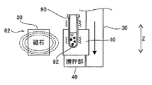
- FIG. 1 is a schematic diagram showing an outline of a BF separator according to an embodiment.
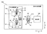
- FIG. 2 is a schematic diagram illustrating a configuration example in which a discharge pipe is provided in the BF separation device.
- FIG. 3A is a schematic diagram for explaining a BF separation method according to an embodiment.
- FIG. 3B is a schematic diagram for explaining a BF separation method according to an embodiment.
- FIG. 3C is a schematic diagram for explaining a BF separation method according to an embodiment.
- FIG. 4 is a schematic diagram showing an outline of a sample analyzer according to an embodiment.
- FIG. 5 is a schematic diagram illustrating a configuration example of the BF separation device.
- FIG. 6A is a diagram illustrating a first configuration example of the holding unit and the magnet in the separated position.
- FIG. 6A is a diagram illustrating a first configuration example of the holding unit and the magnet in the separated position.
- FIG. 6B is a diagram illustrating a first configuration example of the holding unit and the magnet in the approach position.
- FIG. 7A is a diagram illustrating a second configuration example of the holding unit and the magnet in the separated position.
- FIG. 7B is a diagram illustrating a second configuration example of the holding unit and the magnet in the approach position.
- FIG. 8 is a diagram illustrating an example in which the holding unit moves to the container installation position.
- FIG. 9 is a diagram showing combinations (A) to (F) of the positional relationship between the approach position, the separation position, and the container installation position.
- FIG. 10 is a diagram illustrating a configuration example of a BF separation device including a guide unit.
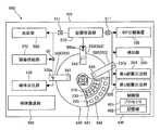
- FIG. 11 is a schematic plan view showing a configuration example of the sample analyzer.
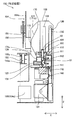
- FIG. 12 is a longitudinal sectional view of the BF separator in the approach position.
- FIG. 13 is a longitudinal cross-sectional view of the BF separator in the separated position.
- FIG. 14 is a longitudinal sectional view of the BF separator at the container installation position.
- FIG. 15A is a schematic diagram illustrating the positions of the guide portion and the rotating body at the approach position.
- FIG. 15B is a schematic diagram illustrating the positions of the guide unit and the rotating body at the container installation position.
- FIG. 15C is a schematic diagram illustrating the positions of the guide unit and the rotating body at the separation position.
- FIG. 16 is a longitudinal sectional view showing a configuration example of the movement base.
- FIG. 17 is a top view of the BF separator shown in FIG. FIG.
- FIG. 18 is a flowchart showing the flow of the BF separation process of the BF separation device shown in FIG.
- FIG. 19 is a schematic diagram for explaining the contents of the BF separation process shown in FIG.
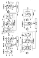
- FIG. 20 is a diagram for explaining the analysis processing of the sample analyzer.
- FIG. 21 is a flowchart for explaining the analysis processing shown in FIG.
- FIG. 22 is a diagram for explaining the prior art.
- the BF separation apparatus 100 is an apparatus for performing a BF separation process for separating a solid phase (Bound) to which a test substance is bound and a liquid component containing a substance (Free) other than the solid phase to which the test substance is bound. is there.
- the test substance may include, for example, predetermined components, cells, and formed components in a blood sample or a urine sample.
- the test substance may be nucleic acids such as DNA (deoxyribonucleic acid), cells and intracellular substances, antigens or antibodies, proteins, peptides, and the like.
- BF separation processing is performed in an automated sample analyzer for analyzing a test substance to be analyzed in a liquid sample.
- a complex in which the test substance, the solid phase, and the labeling substance are bound is formed, and the test substance is automatically detected based on the label.
- the sample analyzer is, for example, an immunoassay device, and binds a test substance, a solid phase, and a labeling substance using an antigen-antibody reaction.
- the immunoassay device detects, for example, an antigen or antibody, protein, peptide, or the like contained in blood as a test substance.
- the immunoassay apparatus acquires serum or plasma as a specimen and quantitatively or qualitatively measures an antigen or an antibody contained in the specimen.
- the antigen-antibody reaction includes not only a reaction between an antigen and an antibody but also a reaction using a specific binding substance such as an aptamer.
- Aptamers are nucleic acid molecules or peptides that are synthesized to specifically bind to a particular substance.
- magnetic particles 82 are used as the solid phase in order to efficiently separate the solid phase and the liquid component.
- the liquid particles 88 other than the magnetic particles 82 are attracted while the magnetic particles 82 combined with the test substance are collected by a magnetic force, thereby separating the magnetic particles 82 and the liquid components 88.
- the magnetic particle 82 is a particle containing a magnetic substance, and its surface is coated with a component for binding to a test substance or the like.
- the magnetic particle may be any particle that contains a magnetic material as a base material and is used for normal immunoassay. For example, magnetic particles using Fe 2 O 3 and / or Fe 3 O 4 , cobalt, nickel, phyllite, magnetite, etc. as the substrate can be used.
- the magnetic particles 82 are directly or indirectly bonded to the test substance. That is, the magnetic particles 82 and the test substance may be directly bound by an antigen-antibody reaction.
- the magnetic particle 82 may be an antibody or an antigen that specifically binds to the antigen or the antibody or a magnetic particle on which the antigen is immobilized.
- the magnetic particles 82 and the test substance may be bound via a capture substance that binds to each of the magnetic particles 82 and the test substance.
- the trapping substance includes a binding substance that binds to the magnetic particles 82.
- a substance that specifically binds to the capture substance is fixed to the magnetic particle 82.
- a combination of biotin and avidin, hapten and anti-hapten antibody, nickel and histatidine tag, glutathione and glutathione-S-transferase, etc. can be used.
- “Avidins” means containing avidin and streptavidin.
- the capture substance includes an antibody or antigen that specifically binds to an antigen or antibody that is a test substance. As a result, the test substance and the capture substance are combined, and the capture substance and the magnetic particles 82 are combined.
- the BF separation device 100 includes a holding unit 10 that holds a container 90 that stores a sample, a magnet 20, a moving mechanism 30, a stirring unit 40, a suction tube 50, Is mainly provided.
- the vertical direction which is the vertical direction, is the Z direction, and one of the horizontal directions orthogonal to the vertical direction is the X direction.
- the container 90 is, for example, a reaction container that has a cylindrical shape that is open at one end and closed at the bottom at the other end, and can store a liquid such as a specimen or a reagent therein.
- the container 90 is a disposable resin container, for example. In this case, the used reaction container can be discarded as it is.
- the container 90 contains a sample containing the magnetic particles 82 and the liquid component 88.
- the holding unit 10 can hold a container 90 containing a sample containing the magnetic particles 82 and the liquid component 88.
- the holding unit 10 holds the container 90 so that the opening of the container 90 faces upward so that the container 90 does not move beyond a specified range.
- the holding unit 10 is a structure in which a holding hole 11 into which the container 90 can be inserted is formed.
- the holding hole 11 is open on the upper surface of the holding unit 10 and can hold the container 90 inserted into the inside from above.
- the holding unit 10 may have a hand structure that holds the side surface of the container 90, for example, or is engaged with a part of the container 90 such as a flange portion provided at the upper end of the container 90. You may have the engagement structure which suspends 90.
- the magnet 20 can collect magnetic particles. That is, the magnet 20 can collect magnetic particles 82 in the container 90 by applying a magnetic force to the container 90 held by the holding unit 10.
- the magnet 20 is a permanent magnet, for example.
- the magnet 20 is provided so as to be relatively movable in a direction toward or away from the holding unit 10. That is, one or both of the magnet 20 and the holding unit 10 can move in a direction in which they approach or separate from each other. In the configuration example of FIG. 1, the magnet 20 can move toward and away from the holding unit 10.
- the relative movement direction between the magnet 20 and the holding unit 10 is not particularly limited. In FIG. 1, the magnet 20 can move relative to the holding unit 10 in a horizontal direction substantially orthogonal to the vertical direction. When the magnet 20 approaches the holding unit 10, the magnetic particles 82 in the container 90 can be collected on the magnet 20 side by the magnetic force of the magnet 20.
- the magnetic force does not substantially act on the magnetic particles 82, or the magnetic force acting on the magnetic particles 82 is weakened so that the magnetic particles 82 can be dispersed by stirring. Therefore, when the magnet 20 is separated from the holding unit 10, the magnetic collection of the magnetic particles 82 is released.
- the moving mechanism 30 can move both the holding unit 10 and the magnet 20 in conjunction with each other.
- the moving mechanism 30 moves the holding unit 10 and moves the magnet 20 in a direction in which the holding unit 10 and the magnet 20 approach or separate from each other in conjunction with the movement of the holding unit 10.
- the moving mechanism 30 can move at least the approach position 61 and the separation position 62 by interlocking both the holding unit 10 and the magnet 20.
- the approach position 61 and the separation position 62 may be positions having different heights, or positions having the same height and separated in the horizontal direction. When the approach position 61 and the separation position 62 are in a positional relationship with different heights, which may be the upper side and the lower side may be the lower side.
- the moving mechanism 30 moves both the holding unit 10 and the magnet 20 so that the height changes at least in the vertical direction.
- the approach position 61 and the separation position 62 are positions having different height directions.
- the moving mechanism 30 moves both the holding unit 10 and the magnet 20 in the vertical direction.
- the magnetism collection process at the approach position 61 and the stirring process described later at the separation position 62 can be performed at different positions in the vertical direction. Therefore, compared with the case where the approach position 61 and the separation position 62 are arranged in the horizontal plane, the horizontal movement distance of the holding unit 10 between the approach position 61 and the separation position 62 is reduced by the height difference. Therefore, the horizontal installation area of the BF separator 100 can be suppressed.
- FIG. 1 shows that each one holding part 10 and the magnet 20 move to the approach position 61 and the separation position 62, and the holding part 10 and the magnet 20 are not provided two each. .
- the moving mechanism 30 is composed of, for example, one or a plurality of linear motion mechanisms.
- the linear motion mechanism includes a combination of a motor and a linear guide, a linear motor, or the like.
- the moving mechanism 30 may be configured to rotate up and down around a horizontal rotation axis.
- the moving mechanism 30 includes a drive source such as at least one motor.
- the moving mechanism 30 moves the holding unit 10 and the magnet 20 in conjunction with different drive sources. Further, for example, the holding unit 10 and the magnet 20 are moved by a common drive source.
- the holding unit 10 and the magnet 20 approach each other due to the relative movement between the holding unit 10 and the magnet 20.
- the holding unit 10 and the magnet 20 are separated from the approach position 61 by the relative movement between the holding unit 10 and the magnet 20. That is, at the approach position 61, the distance D1 is between the holding unit 10 and the magnet 20, and at the separation position 62, the distance D2 is greater than the distance D1 between the holding unit 10 and the magnet 20.
- the magnetic particles 82 in the container 90 held by the holding unit 10 are collected at the approach position 61.
- the separation position 62 the magnetic particles 82 in the container 90 held by the holding unit 10 are demagnetized.
- the holding unit 10 and the magnet 20 move relative to each other in a direction toward or away from each other by a driving source that is separate from the moving mechanism 30.
- the holding unit 10 and the magnet 20 are guided by the moving mechanism 30 to move relative to each other in a direction toward or away from each other without providing a separate drive source.
- the stirring unit 40 can stir the sample in the container 90.
- the stirrer 40 can stir the sample in the container 90 held in the holder 10 at the separation position 62 where the holder 10 and the magnet 20 are separated from each other in the container 90.
- the stirring method by the stirring unit 40 is not particularly limited.
- the stirring unit 40 vibrates the container 90 held by the holding unit 10 and stirs the sample in the container 90.
- the stirring unit 40 vibrates the holding unit 10 that holds the container 90 to stir the sample.
- a vibration motor may be used, or the container 90 or the holding unit 10 may be rotated by a rotation motor.
- the stirring unit 40 stirs by inserting a stirring rod through the opening of the container 90 and stirring the sample.
- the stirring unit 40 may be configured to be movable so that the stirring rod can be taken in and out. In the configuration example of FIG. 1, the stirring unit 40 vibrates the holding unit 10 and stirs the sample in the container 90.
- the stirring unit 40 stirs the sample in the container 90 held by the holding unit 10 at the separation position 62. That is, the stirring unit 40 is configured so that the magnet 20 is separated from the holding unit 10 at the separation position 62 and the magnetic particles 82 in the container 90 held by the holding unit 10 are released from the magnetic collection. Ingredient 88 is agitated.
- unnecessary substances are present together with the magnetic particles 82 bonded to the test substance.
- the unnecessary substance does not contribute to the detection of the test substance or becomes a noise source.
- the unnecessary substance is, for example, other components other than the test substance contained in the specimen, a labeling substance or a capturing substance that has not specifically bound to the magnetic particles 82, and other unspecified contaminants.
- other unnecessary substances can be diffused widely into the liquid component 88.
- the suction tube 50 can suck the liquid component 88 in the container 90.
- the suction tube 50 enters the container 90 held by the holding unit 10 at the approach position 61 where the holding unit 10 and the magnet 20 approach each other, and sucks the liquid component 88 in the container 90.
- the suction pipe 50 is connected to a fluid circuit through a liquid supply path (not shown), for example, and can suck liquid from the tip.
- the suction tube 50 sucks the liquid component 88 in the container 90 held by the holding unit 10 at the approach position 61.
- the suction tube 50 is configured to be movable so that it can enter and retreat into the container 90 held by the holding unit 10, for example.
- the suction pipe 50 is provided at a position corresponding to the holding unit 10 arranged at the approach position 61, and the container 90 held by the holding unit 10 is moved to the approach position 61 by the moving mechanism 30, thereby Enter 90.
- the suction tube 50 sucks the liquid component 88 in the container 90 in a state where the magnet 20 approaches the holding unit 10 at the approach position 61 and the magnetic particles 82 in the container 90 held by the holding unit 10 are collected. To do. As a result of the suction, other unnecessary substances contained in the liquid component 88 are discharged out of the container 90 together with the liquid component 88 while leaving the magnetic particles 82 in the container 90. Thereby, the magnetic particle 82 to which the test substance is bound and the liquid component 88 containing a substance other than the magnetic particle 82 to which the test substance is bound are separated.
- the stirring of the sample by the stirring unit 40 and the suction of the liquid component 88 by the suction pipe 50 are performed at different height positions.
- the stirring of the sample by the stirring unit 40 and the suction of the liquid component 88 by the suction tube 50 are both performed in a state where the container 90 is held by the holding unit 10.
- the holding unit 10 maintains the state in which the container 90 is held without being taken out in the process of sucking the liquid component 88 at the approach position 61 and stirring the sample at the separation position 62.
- the BF separator 100 includes the moving mechanism 30 that moves the magnet 20 in the direction in which the holding unit 10 and the magnet 20 approach or move away in conjunction with the movement of the holding unit 10. Therefore, the holding unit 10 and the magnet 20 can be moved to the separated position 62 and the approaching position 61 where they are separated by simply moving the holding unit 10 on which the container 90 is installed. Therefore, BF separation magnetic flux collection, suction tube insertion, suction, and stirring can be performed at a position different from the container installation position, and the container 90 and the magnet are in a positional relationship for performing the magnetic flux collection processing with a simple configuration. 20 and the container 90 and the magnet 20 can be moved to a positional relationship for performing the stirring process. Therefore, it is possible to improve the degree of freedom of the device configuration.
- the BF separation device 100 includes a discharge pipe 51 that discharges the cleaning liquid 55 into the container 90 held by the holding unit 10 at the approach position 61.
- the discharge pipe 51 can discharge the cleaning liquid 55 into the container 90.
- the discharge pipe 51 enters the container 90 held by the holding unit 10 and discharges the cleaning liquid 55 into the container 90.
- the discharge pipe 51 is connected to the cleaning liquid reservoir through, for example, a liquid supply path and a fluid circuit (not shown), and can discharge the cleaning liquid 55 from the tip.
- the discharge pipe 51 is configured to be movable so as to enter and retreat into the container 90 held by the holding unit 10.
- the discharge pipe 51 may be configured to enter the container 90 when the container 90 held by the holding unit 10 is moved to the approach position 61 by the moving mechanism 30.
- the liquid 20 is attracted by the suction pipe 50 in a state where the magnet 20 approaches the holding part 10 at the approach position 61 and the magnetic particles 82 in the container 90 held by the holding part 10 are collected. Then, the cleaning liquid 55 is discharged into the container 90 after the completion.
- the stirring unit 40 stirs the sample including the magnetic particles 82 and the cleaning liquid 55 in the container 90. As a result, other unnecessary substances nonspecifically adsorbed on the magnetic particles 82 in the container 90 are dispersed in the cleaning liquid 55. That is, the magnetic particles 82 to which the test substance is bonded are cleaned by the cleaning liquid 55.
- both the suction of the liquid component 88 by the suction pipe 50 and the discharge of the cleaning liquid 55 by the discharge pipe 51 can be performed at the approach position 61, and therefore the suction of the liquid component 88 and the discharge of the cleaning liquid 55 are performed at different positions.
- Compared with the apparatus configuration can be simplified.
- the BF separation method of the present embodiment is a method for performing BF separation processing by a BF separation device, and executes the following steps. That is, the BF separation method of the present embodiment is (1) The magnet 20 is moved closer to the holding unit 10 in conjunction with the movement of the holding unit 10 holding the container 90 containing the sample containing the magnetic particles 82 and the liquid component 88 (see FIG. 3A). (2) The liquid component 88 in the container 90 held by the holding unit 10 at the approach position 61 where the holding unit 10 and the magnet 20 approach each other is sucked (see FIG.
- (1) The movement and approach of (1) are performed prior to (2) suction of the liquid component 88.
- (2) The suction of the liquid component 88 is performed prior to (3) discharge of the cleaning liquid 55.
- the movement and separation of (4) are performed prior to (5) stirring of the sample.
- (2) The suction of the liquid component 88, (3) the discharge of the cleaning liquid 55, and (5) the stirring of the sample are carried out in this order, thereby leaving the magnetic particles 82 combined with the test substance in (2).
- the magnetic particles 82 and the remaining unnecessary substances can be dispersed in the cleaning liquid 55.
- the holding unit 10 and the magnet 20 are moved in conjunction with each other by the above-described configuration. Therefore, the holding unit 10 and the magnet 20 can be simply moved by moving the holding unit 10 in which the container 90 is installed. Can be moved to the separated position 62 and the approached position 61 where they are separated. Therefore, BF separation magnetic flux collection, suction tube insertion, suction, and stirring can be performed at a position different from the container installation position, and the container 90 and the magnet are in a positional relationship for performing the magnetic flux collection processing with a simple configuration. 20 and the container 90 and the magnet 20 can be moved to a positional relationship for performing the stirring process. Therefore, it is possible to improve the degree of freedom of the device configuration.
- the sample analyzer 500 is an apparatus for analyzing a measurement sample prepared by adding a predetermined reagent to a sample collected from a subject.
- the subject is mainly a human but may be an animal other than a human.
- the sample analyzer 500 performs analysis for clinical examination or medical research of a sample collected from a patient, for example.
- the specimen is a biological specimen.
- the specimen derived from a living body is, for example, blood (whole blood, serum or plasma) collected from a subject, or a liquid obtained by subjecting blood to a predetermined pretreatment.
- the sample analyzer 500 is an immunoassay device, for example.
- the sample analyzer 500 performs a BF separation process on a sample including the test substance 81, the magnetic particles 82 that bind to the test substance 81, and the labeling substance 83 that binds to the test substance 81. After separating the substance other than the complex in which the substance 81, the magnetic particle 82 and the labeling substance 83 are bound, the test substance 81 is detected based on the labeling of the labeling substance 83.
- the sample analyzer 500 for example, prepares a measurement sample including a test substance 81, a magnetic particle 82, and a labeling substance 83 by adding one or more kinds of predetermined reagents to the specimen. For example, the sample analyzer 500 acquires a sample prepared in advance and analyzes the acquired sample.
- the sample analyzer 500 includes a container transfer unit 510, a BF separation device 100 shown in FIG. 1, and a detection unit 520.
- the container transfer unit 510 can transfer a container 90 that contains a sample containing a test substance 81, magnetic particles 82 that bind to the test substance 81, and a labeling substance 83 that binds to the test substance 81.
- the container transfer unit 510 can transfer the containers 90 to the BF separation device 100 and the detection unit 520, respectively.
- the container transfer unit 510 includes a gripping unit that grips the container 90 and a moving mechanism for moving the gripping unit.
- the gripping portion may have a hand structure that holds the side surface of the container 90, for example, or is engaged with a part of the container 90 such as a flange portion provided at the upper end of the container 90. You may have the engagement structure which suspends 90.
- the container transfer unit 510 has a configuration for moving a structure in which the holding hole 11 into which the container 90 can be inserted is formed.
- the container transfer unit 510 has a conveyor structure that transfers a plurality of containers 90 along a predetermined track.
- the BF separator 100 acquires the container 90 containing the sample from the container transfer unit 510. That is, the container 90 is installed in the holding unit 10 by the container transfer unit 510.
- the BF separation device 100 performs the above-described BF separation process on the sample in the container 90 held by the holding unit 10.
- the BF separation device 100 may include the discharge pipe 51 shown in FIG.
- the detection unit 520 can detect the test substance 81 combined with the magnetic particles 82 in the container 90.
- the detection unit 520 receives the container 90 that contains the sample after the BF separation process is performed by the BF separation device 100 from the container transfer unit 510.
- the detection unit 520 detects the test substance 81 combined with the magnetic particles 82 in the container 90 from which the liquid component 88 has been separated by the BF separation device 100. For example, the detection unit 520 detects a signal based on a label included in the complex in the container 90.
- the sample analyzer 500 analyzes, for example, the presence / absence of the test substance 81, the number or amount of the test substance 81, the concentration or the existence ratio of the test substance 81, and the like.
- the detection may be performed by an appropriate method according to the type of label used for the labeling substance 83, and the detection method is not particularly limited.
- the labeling substance 83 contains a label that binds to the test substance 81 by an antigen-antibody reaction and can be detected by the detection unit 520.
- the labeling substance 83 is not particularly limited as long as it is an antibody containing a known label. When a capture substance is used, the labeling substance 83 may bind to the capture substance.
- the label contained in the labeling substance include enzymes, fluorescent substances, and radioisotopes. Examples of the enzyme include alkaline phosphatase (ALP), peroxidase, glucose oxidase, tyrosinase, and acid phosphatase.
- the fluorescent substance fluorescein isothiocyanate (FITC), green fluorescent protein (GFP), luciferin and the like can be used.
- FITC fluorescein isothiocyanate
- GFP green fluorescent protein
- luciferin luciferin
- the radioisotope 125I, 14C, 32P, or the like can be used.
- the label used for the labeling substance 83 is an enzyme.
- the substrate for the enzyme of the labeling substance 83 may be appropriately selected from known substrates according to the enzyme used.
- the substrate is CDP-Star®, (4-chloro-3- (methoxyspiro ⁇ 1,2-dioxetane-3,2 ′-(5′-chloro) trixiro [3.3.1.13,7] decan ⁇ -4-yl) phenyl phosphate disodium), CSPD® (3- (4-methoxyspiro ⁇ 1,2-dioxetane-3,2- ( Chemiluminescent substrates such as 5′-chloro) tricyclo [3.3.1.13,7] decan ⁇ -4-yl) phenyl phosphate disodium); p-nitrophenyl phosphate, 5-bromo-4-chloro- Luminescent substrates such as 3-indolyl phosphate (BCIP), 4-nitroblue
- the detection unit 520 measures light, color, etc. generated by reacting a substrate with the enzyme.
- a spectrophotometer, a luminometer, or the like can be used as the detection unit 520.
- the labeling substance is a radioisotope, a scintillation counter or the like can be used as the detection unit 520.
- the sample analyzer 500 of the present embodiment includes the BF separation device 100 described above, thereby performing BF separation processing magnetism collection, suction tube insertion, suction, and stirring at a position different from the container installation position. Since the container 90 and the magnet 20 can be moved to a positional relationship for performing the stirring process with a simple configuration, the degree of freedom of the device configuration of the BF separation device 100 can be improved. It becomes. As a result, since the degree of freedom of the configuration related to the BF separation device 100 can be improved in the sample analyzer 500, the degree of freedom of the device configuration as a whole of the sample analyzer 500 can be improved.
- the moving mechanism 30 moves both the holding unit 10 and the magnet 20 in an oblique direction in conjunction with each other.
- the moving mechanism 30 does not have to be linearly moved in the vertical direction as shown in FIG.
- the moving mechanism 30 moves both the holding unit 10 and the magnet 20 in different directions in conjunction with each other.
- the moving mechanism 30 moves both the holding unit 10 and the magnet 20 so as to descend while approaching each other toward the approach position 61, and moves the holding unit 10 and the magnet toward the separation position 62. Both 20 are moved so as to rise while being separated from each other.
- the moving mechanism 30 may include a first moving mechanism for moving the holding unit 10 and a separate second moving mechanism for moving the magnet 20.
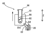
- the holding unit 10 and the magnet 20 are connected via a connecting member 21 so as to be relatively movable.
- the magnet 20 is disposed on the lower surface side of the holding portion 10, and the connecting member 21 extending downward from the lower surface of the holding portion 10 passes therethrough.
- the magnet 20 is relatively movable in a direction approaching or leaving the holding unit 10 between a retaining portion 21 a fixed to the lower end of the connecting member 21 and the lower surface of the holding unit 10.
- the moving mechanism 30 raises the holding unit 10 to move it to the upper separation position 62.
- the magnet 20 is separated from the holding unit 10 by a distance D2 by its own weight.
- the magnetic collection by the magnet 20 is released.
- the moving mechanism 30 lowers the holding unit 10 to move it to the approach position 61 on the lower side.
- a guide portion 31 that supports the magnet 20 by contacting the magnet 20 descending together with the holding portion 10 by the moving mechanism 30 from below is disposed.
- the magnet 20 moves relative to the holding unit 10 in a direction approaching the distance D ⁇ b> 1 ( ⁇ D ⁇ b> 2) by being in contact with the guide unit 31 and being restricted in movement.
- the magnetic particles 82 in the container 90 are collected on the bottom surface side of the container 90 by the magnet 20.
- the holding unit 10 and the magnet 20 relatively move in a non-linear path.
- the magnet 20 is disposed on the side surface side of the holding unit 10 and is held so as to be rotatable around a rotation center 22 a via a connecting member 22 provided at a corner of the holding unit 10.
- the connecting member 22 holds the magnet 20 at a position separated from the holding unit 10 by a distance D ⁇ b> 2 by a rotation stopper (not shown).
- FIG. 7B when the holding unit 10 reaches the approach position 61 on the lower side, the magnet 20 comes into contact with the guide unit 31 and rotates around the rotation center 22 a with respect to the holding unit 10.
- the moving mechanism 30 is connected to the holding unit 10 and moves the holding unit 10, but the holding unit 10 and the magnet 20 are connected to each other. Both the part 10 and the magnet 20 are moved in conjunction with each other.
- the moving mechanism 30 moves the holding unit 10 and the magnet 20 in conjunction with the container installation position 63 as well as the approach position 61 and the separation position 62.
- the container installation position 63 is at a height different from the approach position 61 and the separation position 62.
- the moving mechanism 30 is configured to move the holding unit 10 to the container installation position 63 where the container 90 is installed and removed in addition to the approach position 61 and the separation position 62. That is, the container transfer unit 510 installs the container 90 and removes the container 90 from the holding unit 10 disposed at the container installation position 63.
- the container transfer unit 510 installs the container 90 and removes the container 90 from the holding unit 10 disposed at the container installation position 63.
- the container 90 is taken in and out of the holding unit 10 at the approach position 61
- there is a possibility that an operation for avoiding the interference between the suction pipe 50 and the container 90 to be carried may be required.
- the container 90 is taken in and out of the holding unit 10 at the container installation position 63, interference between the container 90 being carried and each part of the BF separation device 100 can be easily avoided.
- the approach position 61 is disposed above the separation position 62.
- the container installation position 63 is disposed below the approach position 61 and the separation position 62. That is, from the top, the approach position 61, the separation position 62, and the container installation position 63 are arranged in this order.
- the height order of the approach position 61, the separation position 62, and the container installation position 63 is not limited to that shown in FIG. FIG. 9 shows combinations (A) to (F) in the order of height of the approach position 61, the separation position 62, and the container installation position 63.
- the upper side in FIG. 9 indicates a higher position, and the lower side in FIG. 9 indicates a lower position.
- the container installation position 63, the separation position 62, and the approach position 61 are arranged in this order from above.
- the order of height of the approach position 61, the separation position 62, and the container installation position 63 may be any combination of (A) to (F) in FIG.
- the moving mechanism 30 may move the holding unit 10 and the magnet 20 to a fourth position or a fifth position having a height different from the approach position 61, the separation position 62, and the container installation position 63.
- the moving mechanism 30 is provided so as to extend linearly in the vertical direction, and moves both the holding unit 10 and the magnet 20 in the vertical direction.
- the moving mechanism 30 moves both the holding unit 10 and the magnet 20 to the lower approach position 61 and the upper separation position 62 with respect to the approach position 61.
- the holding unit 10 and the magnet 20 are provided so as to be movable in the vertical direction by the moving mechanism 30.
- the holding unit 10 and the magnet 20 can move relative to each other in a direction intersecting the up-down direction, which is the moving direction by the moving mechanism 30, and can approach or separate. In the example of FIG. 10, the magnet 20 can move in the horizontal direction intersecting the vertical direction with respect to the holding unit 10.
- the moving mechanism 30 is configured to move the holding unit 10 and the magnet 20 in the vertical direction, and the holding unit 10 and the magnet 20 are interlocked with the vertical movement. , Move relative to each other so as to approach or separate in the direction intersecting the vertical direction. Accordingly, the moving mechanism 30 only needs to move the holding unit 10 and the magnet 20 simply in the vertical direction and does not need to be moved in the horizontal direction, so that the configuration of the moving mechanism 30 can be simplified.
- the installation area of 30 can be reduced. As a result, the installation area of the BF separator 100 can be further reduced.
- the BF separation device 100 includes a guide unit 31 that contacts at least one of the holding unit 10 and the magnet 20 that are moved by the moving mechanism 30 and moves the holding unit 10 and the magnet 20 closer to or away from each other.
- a guide unit 31 that contacts at least one of the holding unit 10 and the magnet 20 that are moved by the moving mechanism 30 and moves the holding unit 10 and the magnet 20 closer to or away from each other.
- the guide portion 31 contacts the magnet 20 out of the holding portion 10 and the magnet 20 to guide the movement of the magnet 20.
- the guide portion 31 extends in the vertical direction along the moving direction of the moving mechanism 30. Further, the position of the guide unit 31 changes in the horizontal direction so as to approach the holding unit 10 in the horizontal direction intersecting the vertical direction as it approaches the approaching position 61 and to move away from the holding unit 10 in the horizontal direction as it approaches the separation position 62. doing. Thereby, when the magnet 20 is moved in the vertical direction by the moving mechanism 30, the guide unit 31 moves the magnet 20 toward the holding unit 10 as it approaches the approaching position 61, and holds the magnet 20 as it approaches the separating position 62. Move to the side away from the part 10.
- the guide unit 31 uses a driving force that causes the moving mechanism 30 to move the holding unit 10 and the magnet 20 between the approaching position 61 and the separating position 62, so that the holding unit 10 is moved in a direction different from the moving direction of the moving mechanism 30. And at least one of the magnets 20 is moved.
- the guide unit 31 has a structure that guides the guide unit 31 so as to move along the guide unit 31 by engaging with at least one of the holding unit 10 and the magnet 20 as a guide target, such as a rail or a guide groove.
- a guide target such as a rail or a guide groove.
- the guide part 31 is a rail
- the guide target is engaged with the guide part 31 so as to move on the rail.
- the guide part 31 is a guide groove
- at least a part of the guide object is disposed in the guide groove and engages with the guide part 31 so as to move in the guide groove.
- the guide part 31 may guide the holding part 10 instead of the magnet 20.
- the guide part 31 may guide both the magnet 20 and the holding part 10.
- the stirring unit 40 is connected to the holding unit 10 so as to move together with the holding unit 10, and is configured to stir the sample in the container 90 by driving the holding unit 10. Accordingly, the stirring unit 40 can be moved integrally with the holding unit 10 by the moving mechanism 30. Therefore, for example, the apparatus configuration can be simplified as compared with a configuration (see FIG. 1) in which the holding unit 10 is connected to the agitation unit 40 that is fixedly provided by moving to the separation position 62.
- the magnet 20 is disposed on the side of the holding unit 10 and is provided so as to approach or separate from the side surface of the container 90 held by the holding unit 10.
- the magnetic particles 82 can be collected on the side surface side of the container 90 at the approach position 61. Therefore, unlike the case where magnetism is collected on the bottom surface side of the container 90 as shown in FIG. 6B, the liquid component 88 is sucked into the container 90 without sucking the magnetized magnetic particles 82 when the liquid component 88 is attracted by the suction pipe 50. Therefore, the magnetic particles 82 and the liquid component 88 can be effectively separated.
- the sample analyzer 500 is an immunoassay device that detects a test substance in a specimen by using an antigen-antibody reaction.
- the specimen is serum or plasma.
- the sample analyzer 500 includes a container transfer unit 510, a BF separation device 100, and a detection unit 520.
- the sample analyzer 500 includes a housing 505, a sample dispensing unit 530, a reagent cold storage 540, a reagent dispensing unit 550, a sample transport unit 560, and a container supply unit 570. And a reaction unit 580.
- the sample analyzer 500 includes a control unit 400 for controlling the above-described units.
- the housing 505 has a box shape capable of accommodating each part of the sample analyzer 500 inside.
- the case 505 may be configured to accommodate each part of the sample analyzer 500 on a single level, or has a hierarchical structure in which a plurality of levels are provided in the vertical direction. You may allocate and arrange
- the sample transport unit 560 is configured to transport a sample collected from the subject to a suction position by the sample dispensing unit 530.
- the sample transport unit 560 can transport a rack in which a plurality of test tubes containing samples are installed to a predetermined sample suction position.
- the sample dispensing unit 530 can aspirate the sample conveyed by the sample conveyance unit 560 and dispense the aspirated sample into the container 90.
- the specimen dispensing unit 530 includes a pipette connected to a fluid circuit for performing suction and discharge, and a moving mechanism that moves the pipette.
- the sample dispensing unit 530 attaches a dispensing tip set in a tip supply unit (not shown) to the tip of the pipette and sucks a predetermined amount of the sample in the transported test tube into the dispensing tip.
- the sample dispensing unit 530 dispenses the aspirated sample into a container 90 disposed at a predetermined sample dispensing position. After dispensing, the sample dispensing unit 530 removes the dispensing tip from the tip of the pipette and discards it.
- the container supply unit 570 can store a plurality of unused containers 90.
- the container supply unit 570 can supply unused empty containers 90 to the container transfer unit 510 one by one at a predetermined container supply position.
- the container transfer unit 510 can transfer the container 90.
- the container transfer unit 510 acquires an empty container 90 from the container supply position, and puts the container at each processing position such as the BF separation device 100, the sample dispensing unit 530, the reagent dispensing unit 550, the reaction unit 580, and the detection unit 520. 90 is transferred.
- the container transfer part 510 is comprised by the holding part which has the installation hole of the catcher 511 or the container 90 which hold
- the moving mechanism moves in the direction of one axis or a plurality of axes by, for example, one or a plurality of linearly movable linear movement mechanisms.
- the moving mechanism can move, for example, in three orthogonal directions in the vertical direction and two horizontal directions.
- the moving mechanism may include an arm mechanism that rotates horizontally around the rotation axis and an articulated robot mechanism.
- One or more container transfer units 510 are provided depending on the arrangement of the processing positions of the sample dispensing unit 530, the reagent dispensing unit 550, the reaction unit 580, the detection unit 520, and the like in the housing 505.
- the reaction unit 580 includes a heater and a temperature sensor, holds the container 90, and warms and reacts the sample stored in the container 90.
- the sample and reagent accommodated in the container 90 react by heating.
- One or a plurality of reaction units 580 are provided in the housing 505.
- the reaction unit 580 may be fixedly installed in the housing 505 or may be movably provided in the housing 505. When the reaction unit 580 is configured to be movable, the reaction unit 580 can also function as a part of the container transfer unit 510.
- the reagent cold storage 540 includes a container holding unit 542 and a cooling mechanism in the case 541.
- the container holding part 542 holds a reagent container.
- the cooling mechanism keeps the reagent in the reagent container at a constant temperature suitable for storage.
- the case 541 has an internal space defined by a circular case top surface and case bottom surface, and a cylindrical case side surface.
- the case 541 includes a heat insulating material and insulates the inside and the outside of the case 541. Thereby, the reagent container can be stored cold.
- the reagent cooler 540 has a plurality of holes 543 through which the reagent dispensing unit 550 enters the reagent cooler 540.
- the container holding part 542 is formed to hold a plurality of reagent containers side by side in the circumferential direction.
- the container holding part 542 can hold a plurality of reagent containers side by side in the radial direction. That is, the container holding part 542 can arrange the row
- the container holding part 542 can independently rotate a row of a plurality of concentric reagent containers in the circumferential direction.
- the plurality of holes 543 have different radial positions so as to correspond to any of the rows of reagent containers arranged concentrically.
- the container holding unit 542 places a desired reagent container selected from the corresponding row of reagent containers at a position immediately below each of the plurality of holes 543 provided according to the reagent dispensing unit 550. Can be placed. As a result, the reagent in the reagent container arranged at a position immediately below the hole 543 is aspirated by the reagent dispensing unit 550.
- reagent containers 210, 220, and 230 that respectively store R1 reagent, R2 reagent, and R3 reagent described later are set.
- the reagent dispensing unit 550 sucks the reagent in the reagent container, and dispenses the sucked reagent into the container 90.
- the reagent dispensing unit 550 can move a pipette 550a for aspirating and discharging a reagent in the horizontal direction between the hole 543 and a predetermined reagent dispensing position.
- the reagent dispensing unit 550 can move the pipette 550a in the vertical direction to pass through the hole 543 from above the hole 543 and enter the reagent container, and pipette up to a position above the hole 543. 550a can be retreated.
- the pipette 550a is connected to a fluid circuit (not shown), sucks a predetermined amount of reagent from the reagent container of the container holding unit 542, and dispenses the reagent into the container 90 transferred to the reagent dispensing position.
- Three reagent dispensing units 550 are provided for each of the R1 reagent to R3 reagent, for example.
- a single reagent dispensing unit 550 may dispense multiple types of reagents.
- the reagent dispensing unit 550 dispenses the first reagent dispensing unit 551 for dispensing the R1 reagent in the reagent container 210 and the R2 reagent in the reagent container 220.
- the reagent dispensing unit 550 includes a fourth reagent dispensing unit 554 for dispensing the R4 reagent and a fifth reagent dispensing unit 555 for dispensing the R5 reagent.
- the first reagent dispensing unit 551 can move the pipette 550a between the hole 543 for aspirating the R1 reagent from the reagent container 210 containing the R1 reagent and a predetermined R1 reagent dispensing position.
- the second reagent dispensing unit 552 can move the pipette 550a between the hole 543 for aspirating the R2 reagent from the reagent container 220 containing the R2 reagent and a predetermined R2 reagent dispensing position.
- the third reagent dispensing unit 553 can move the pipette 550a between a hole 543 for aspirating the R3 reagent from the reagent container 230 containing the R3 reagent and a predetermined R3 reagent dispensing position.
- the fourth reagent dispensing unit 554 and the fifth reagent dispensing unit 555 are provided at positions separated from the reagent cold storage 540.
- the fourth reagent dispensing unit 554 and the fifth reagent dispensing unit 555 are connected to a reagent container (not shown) containing R4 reagent and R5 reagent via a liquid feeding tube, respectively.
- the reagent can be discharged into the transferred container 90.
- the BF separator 100 has a function of executing a BF separation process for separating the liquid phase and the solid phase from the container 90.
- one or more BF separators 100 are provided in the sample analyzer 500.
- the BF separator 100 sucks the liquid component in the container 90 with the suction pipe 50 and supplies the cleaning liquid with the discharge pipe 51 in a state where the magnetic particles 82 on which immune complexes to be described later are formed are collected.
- the suction pipe 50 and the discharge pipe 51 are each connected to a fluid circuit (not shown). Thereby, an unnecessary substance contained in the liquid component can be separated from the magnetic particles 82 and removed.
- the detection unit 520 includes a photodetector 521 (see FIG. 20) such as a photomultiplier tube.
- the detection unit 520 measures the amount of antigen contained in the sample by acquiring light generated in the reaction process between the labeled antibody that binds to the antigen of the sample subjected to various processes and the luminescent substrate with the photodetector 521. To do.
- the control unit 400 includes a processor 401 such as a CPU and a storage unit 402 such as a ROM, a RAM, and a hard disk.
- the processor 401 functions as a control unit of the sample analyzer 500 by executing a control program stored in the storage unit 402.
- the control unit 400 controls the operation of each unit of the sample analyzer 500 described above.
- the BF separator 100 includes a holding unit 110, a magnet 120, a moving mechanism 130, a stirring unit 140, a suction pipe 150, and a discharge pipe 151.
- the moving mechanism 130 is configured to move the holding unit 110 and the magnet 120 in the vertical direction.
- the moving mechanism 130 interlocks both the holding unit 110 and the magnet 120, and in addition to the approach position 61 (see FIG. 12) and the separation position 62 (see FIG. 13), the container 90 is installed and removed. It is comprised so that it may move to the installation position 63 (refer FIG. 14).
- the approach position 61, the separation position 62, and the container installation position 63 have different heights. 12 to 14, the container installation position 63, the separation position 62, and the approach position 61 are arranged in this order from above.
- the container installation position 63 is arranged above the approach position 61 and the separation position 62. Accordingly, the suction tube 150 that sucks the liquid component at the approach position 61 and the stirring unit 140 that stirs the sample at the separation position 62 are less likely to become an obstacle when the container 90 is installed and taken out at the container installation position 63. be able to. Therefore, it is easy to avoid interference with the configuration related to taking in and out of the container 90 with respect to the holding unit 110.
- the moving mechanism 130 includes a common driving unit 131 for moving both the holding unit 110 and the magnet 120. Thereby, since the drive source of the holding
- the BF separator 100 includes a moving base 160 provided with a holding unit 110 and a magnet 120.
- the moving mechanism 130 moves the moving base 160 by the driving unit 131.
- both the holding unit 110 and the magnet 120 can be moved in conjunction with each other only by the movement mechanism 130 moving the movement base 160. Therefore, the configuration of the moving mechanism 130 can be further simplified.
- the moving mechanism 130 is configured to move the holding unit 110, the magnet 120, and the stirring unit 140 in conjunction with each other. Thereby, the moving mechanism 130 can move not only the holding unit 110 and the magnet 120 but also the stirring unit 140 in conjunction with each other. Therefore, the apparatus configuration for stirring the sample in the container 90 held in the holding unit 110 at the separation position 62 by the stirring unit 140 can be simplified.
- the stirring unit 140 is provided on the moving base 160 and is configured to stir the sample in the container 90 by driving the holding unit 110.
- the stirring unit 140 since not only the holding
- the stirring unit 140 unlike the case where the stirring bar 140 enters the container 90, for example, the stirring unit 140 only needs to apply vibration to the holding unit 110. Therefore, the configuration of the stirring unit 140 can be simplified and the stirring unit 140 can be made compact.
- the moving mechanism 130 includes a drive unit 131, a transmission mechanism 132, and a guide rail 133.
- the drive unit 131 is installed in the lower part of the BF separator 100.
- the drive unit 131 is a motor such as a stepping motor or a servo motor.
- the transmission mechanism 132 connects the output shaft of the driving unit 131 and the moving base 160, and transmits the driving force of the driving unit 131 to the moving base 160.
- the drive unit 131 moves the movement base 160 to each of the approach position 61 to the container installation position 63 via the transmission mechanism 132.
- the transmission mechanism 132 is a belt-pulley mechanism.
- the movement base 160 is fixed to a predetermined position of the belt of the transmission mechanism 132 via the bracket, and is moved along with the movement of the belt.
- the transmission mechanism 132 can employ a known configuration, for example, a rack and pinion mechanism, or a linear motion mechanism using a ball shaft and a ball nut.
- the moving mechanism 130 may be configured to directly apply the driving force generated by the driving unit 131 to the moving base 160, such as a linear motor, in which case the transmission mechanism 132 is unnecessary.
- the guide rail 133 is provided so as to extend linearly in the vertical direction.
- the moving base 160 is provided with a slider (not shown) that moves linearly along the guide rail 133. Accordingly, the moving mechanism 130 drives the moving base 160 by the drive unit 131 and the transmission mechanism 132 and linearly moves the moving base 160 along the guide rail 133 in the vertical direction.
- the drive unit 131, the guide rail 133, and the transmission mechanism 132 are attached to the chassis 105 of the BF separation device 100.
- the BF separation device 100 is in contact with at least one of the holding unit 110 and the magnet 120 that are moved by the moving mechanism 130 to approach or separate the holding unit 110 and the magnet 120.
- Part 170 is provided.
- the BF separator 100 includes an urging member 125 (see FIG. 13) that urges the holding unit 110 and the magnet 120 toward each other.
- the guide part 170 is configured to separate the holding part 110 and the magnet 120 against the urging force of the urging member 125 and to bring the holding part 110 and the magnet 120 closer by the urging force of the urging member 125. Yes.
- the guide part 170 may be formed so as to separate the holding part 110 and the magnet 120 against the urging force of the urging member 125.
- the guide part 170 causes the holding part 110 and the magnet 120 to be separated. Therefore, it is not necessary to provide both a guide for making the holding unit 110 and the magnet 120 close to each other. Therefore, the structure of the guide part 170 can be simplified.
- the guide part 170 has an inclined surface 171 that is inclined with respect to the moving direction from the approach position 61 to the separation position 62 so as to separate the holding part 110 and the magnet 120 from the approach position 61 to the separation position 62.
- at least one of the holding unit 110 and the magnet 120 includes a rotating body 121 that rolls on the inclined surface 171. Accordingly, when the rotating body 121 rolls on the inclined surface 171 of the guide portion 170, at least one of the holding portion 110 and the magnet 120 is different from the moving direction from the approach position 61 to the separation position 62 by the moving mechanism 130. It can be moved relative to the direction. As a result, the holding unit 110 and the magnet 120 can be moved closer to or away from each other with a simple configuration including the inclined surface 171 and the rotating body 121.
- the magnet 120 is provided with a rotating body 121.
- the rotating body 121 is a roller having a circular outer peripheral surface.
- the rotating body 121 is provided at a position where it can come into contact with the guide part 170 as the moving base 160 moves up and down by the moving mechanism 130.
- the rotating body 121 is provided integrally with the magnet 120 so as to be movable in the horizontal direction.
- the guide portion 170 is configured by a plate-like member having an inclined surface 171 formed thereon.
- the inclined surface 171 is inclined with respect to the vertical direction in a direction away from the holding unit 110 at the separation position 62.
- the inclined surface 171 is inclined so as to protrude to the left side in the drawing.
- the guide unit 170 includes an inclined surface 171a between the approach position 61 and the separation position 62, and an inclined surface 171b between the container installation position 63 and the separation position 62. including.
- the guide portion 170 includes a flat surface 172 extending linearly in the vertical direction at a height position corresponding to the separation position 62.
- the flat surface 172 is connected to the inclined surface 171a on the lower end side and is connected to the inclined surface 171b on the upper end side.
- the rotating body 121 in the approach position 61 and the container installation position 63, is disposed at a position separated in the horizontal direction with respect to the guide portion 170.
- the rotating body 121 is not in contact with the guide portion 170 at the approach position 61 and the container installation position 63.
- the rotating body 121 is in a position overlapping the inclined surface 171 in the vertical direction.
- the magnet 120 and the holding part 110 are the distance D1.
- the rotating body 121 comes into contact with the inclined surface 171a. Since the magnet 120 is urged toward the holding unit 110 by the urging member 125, the rotating body 121 moves so as to climb the inclined surface 171a while maintaining a contact state with the inclined surface 171a. As a result, the magnet 120 moves horizontally in a direction away from the holding unit 110 against the urging force of the urging member 125.
- the moving mechanism 130 is configured to move the holding unit 110 and the magnet 120 in the vertical direction, and the holding unit 110 and the magnet 120 intersect the vertical direction in conjunction with the vertical movement. Relative movement so as to approach or separate in the direction of movement.
- the holding unit 110 and the magnet 120 approach the distance D ⁇ b> 1 where the magnetic particles 82 in the container 90 are collected, and at the separation position 62, the holding unit 110 and the magnet 120 are in the magnetic particle 82 inside the container 90.
- D2 the distance D2 at which the magnetism is released.
- the magnet 120 is disposed on the side of the holding unit 110 and is provided so as to approach or separate from the side surface of the container 90 held by the holding unit 110.
- the magnet 120 is provided on the guide rail 122 provided on the moving base 160 so as to be movable in the horizontal direction. Thereby, the magnet 120 can be relatively moved on the moving base 160 in a direction approaching or moving away from the holding unit 110.
- the magnet 120 is connected to one end of a biasing member 125 provided in the horizontal direction.
- the other end of the urging member 125 is connected to a fixed portion provided at a position on the holding base 110 side on the moving base 160.
- the biasing member 125 is a tension coil spring, and applies a biasing force to the magnet 120 in a direction approaching the holding unit 110. Due to the biasing force, the magnet 120 approaches or separates from the side surface of the container 90 held by the holding unit 110.
- the holding unit 110 exposes the side surface of the held container 90 on the magnet 120 side so that the magnet 120 and the container 90 held by the holding unit 110 are brought close to each other at the approach position 61. It is configured. As a result, the magnet 120 and the container 90 held by the holding unit 110 can be sufficiently brought close to each other at the approach position 61, so that the magnetic particles 82 can be effectively collected.
- the holding unit 110 includes a holding hole 111 that holds the container 90 and an opening side surface 113 in which an opening that exposes the side surface of the container 90 disposed in the holding hole 111 is formed. That is, the holding part 110 has a peripheral wall part 112 that defines the holding hole 111, and the side surface of the peripheral wall part 112 on the magnet 120 side is the opening side face 113. As shown in FIG. 12, at the approach position 61, the magnet 120 is disposed at a position where it abuts on the opening side surface 113. The urging force of the urging member 125 toward the holding unit 110 is supported by the opening side surface 113 that abuts the magnet 120. That is, the magnet 120 is held at the approach position 61 while being pressed against the opening side surface 113 by the biasing force.
- the magnet 120 can be brought as close as possible to the container 90 in the holding hole 111 at the approach position 61. Further, since the magnet 120 can be positioned by coming into contact with the opening side surface 113, the distance between the magnet 120 and the container 90 at the approach position 61 is kept constant, and the liquid component is collected when the liquid component is sucked by the suction pipe 150. The magnetic state can be stabilized without variation.
- the magnet 120 is also disposed at the position where the magnet 120 abuts on the opening side surface 113 at the container installation position 63 as in the approach position 61. Since the magnet 120 is supported in contact with the opening side surface 113, the rotating body 121 shown in FIGS. 15A to 15C is located at a position away from the guide unit 170 in the horizontal direction at each of the approach position 61 and the container installation position 63. Thus, the guide part 170 is not contacted.
- the peripheral wall part 112 of the holding part 110 has a substantially cylindrical shape.
- the upper end of the peripheral wall 112 is opened to form the holding hole 111, and the lower end of the peripheral wall 112 is closed.
- the upper end part of the surrounding wall part 112 is formed in the flange shape extended toward a radial direction outer side.
- the opening side surface 113 of the peripheral wall portion 112 is formed by a flat surface.
- An opening 114 connected to the holding hole 111 is formed on the opening side surface 113, and the container 90 installed in the holding hole 111 is exposed through the opening 114.
- the stirring unit 140 is connected to the holding unit 110 so as to move together with the holding unit 110.
- the stirring unit 140 is configured to stir the sample in the container 90 by driving the holding unit 110.
- the stirring unit 140 is constituted by a rotary motor attached to the moving base 160.
- the stirring unit 140 is disposed at a position directly below the holding unit 110, and an output shaft 141 directed upward is attached to the bottom of the holding unit 110.
- the output shaft 141 is connected to the holding unit 110 at a position slightly decentered from the center of the holding unit 110 in the horizontal cross section.
- the stirring unit 140 rotates the holding unit 110 eccentrically around the rotation axis in the vertical direction.
- the stirring unit 140 vibrates and stirs the sample in the container 90 held by the holding unit 110.
- An upper end portion of the holding unit 110 is covered with an upper surface cover 161 fixed to the moving base 160, and a rotating portion by the stirring unit 140 is not exposed.
- the top cover 161 is provided with a through hole 162 at a position overlapping the holding hole 111, and the container 90 is set in the holding hole 111 through the through hole 162.
- FIG. 17 is a plan view of the BF separator 100 shown in FIGS.
- the BF separator 100 includes a plurality of processing ports 101 for holding the container 90 and performing BF separation processing. That is, a plurality of processing ports 101 including the holding unit 110 and the magnet 120 are provided.
- the BF separation device 100 includes two processing ports 101.
- the BF separator 100 includes the same number of suction pipes 150 and discharge pipes 151 as the processing ports 101.
- the number of processing ports 101 may be one or three or more.
- the number of suction pipes 150 and the number of discharge pipes 151 may be one or three or more, respectively.
- the number of suction pipes 150 and discharge pipes 151 may not be the same, and the numbers may be different.
- the suction pipe 150 and the discharge pipe 151 may be used in common for the plurality of processing ports 101. That is, the number of suction pipes 150 and discharge pipes 151 smaller than the number of processing ports 101 may be provided.
- the movement base 160 is provided with a plurality of processing ports 101 including the holding unit 110 and the magnet 120.
- the holding unit 110 and the magnet 120 that constitute each processing port 101 are collectively connected to the approach position 61 and the separation position 62 only by providing one common moving mechanism 130. Can be moved to. Therefore, especially when a plurality of processing ports 101 are provided, the moving mechanism 130 can be shared, so that the installation area of the apparatus can be effectively reduced.
- each of the two processing ports 101 includes a stirring unit 140 (see FIG. 16) connected to the holding unit 110.
- Each holding unit 110 is independently stirred by the stirring unit 140.
- the two magnets 120 are provided in a common installation portion 123 and can be horizontally moved integrally on a common guide rail 122 (see FIG. 16).
- One urging member 125 is connected to the installation portion 123, and one urging member 125 is provided so as to urge the two magnets 120 together.
- the suction pipe 150 is provided so as to extend in the vertical direction.
- the suction pipe 150 has a suction port at its lower end, and is connected from the upper end to a fluid circuit (not shown) via a flow passage (not shown) such as a liquid feed tube. Thereby, the suction tube 150 can suck the liquid component in the container 90 from the lower end.
- the discharge pipe 151 is provided so as to extend in the vertical direction.
- the discharge pipe 151 has a discharge port at the lower end, and the upper end is connected to a cleaning liquid container (not shown) via a flow path (not shown) such as a liquid feed tube and a fluid circuit (not shown). ing. Thereby, the discharge pipe 151 can discharge the cleaning liquid into the container 90 from the lower end.
- the BF separator 100 includes a cleaning device 153 for cleaning the suction tube 150.
- the cleaning device 153 may clean the discharge pipe 151.
- the cleaning device 153 is provided at substantially the same height as the holding unit 110 in the approach position 61.
- the suction tube 150 is configured to move between the container 90 held by the holding unit 110 at the approach position 61 and the cleaning device 153.
- the holding part 110 and the cleaning device 153 at the approach position 61 are arranged at substantially the same height, the moving path of the suction pipe 150 between the cleaning device 153 and the container 90 at the approach position 61 is simplified. it can. Therefore, the BF separator 100 can be downsized.
- the cleaning device 153 is provided so as to be aligned with the holding unit 110 in the approach position 61 in the horizontal direction.
- the cleaning device 153 is provided adjacent to the moving base 160 at the approach position 61.
- the cleaning device 153 has a cylindrical shape with an open upper end and a closed lower end, and can store a cleaning liquid therein.
- Two ports 153 a for supplying and discharging the cleaning liquid are provided on the side surface of the cleaning device 153 and communicate with the inside of the cleaning device 153.
- the two ports 153a are connected to the cleaning liquid container and the drainage container via fluid circuits (not shown), respectively.
- the suction tube 150 and the discharge tube 151 enter the cleaning device 153 from above through the opening of the cleaning device 153. Then, the cleaning liquid is supplied into the cleaning device 153, and the suction pipe 150 is cleaned. Since the discharge pipe 151 does not come into contact with the sample in the container 90, cleaning is not always necessary, but it may be periodically cleaned.
- two suction pipes 150 and discharge pipes 151 are attached to the nozzle moving mechanism 154 so that they can enter the container 90.
- the nozzle moving mechanism 154 is provided with two sets of suction pipes 150 and discharge pipes 151 corresponding to the two processing ports 101. Further, the same number of cleaning units 153 as the processing ports 101 are provided.
- the suction pipe 150 and the discharge pipe 151 of each processing port 101 can enter and retreat from the inside of the container 90 and the cleaning device 153 held by the corresponding holding unit 110 by the nozzle moving mechanism 154.
- the nozzle moving mechanism 154 includes a tube support portion 154a that moves while supporting the two sets of suction tubes 150 and discharge tubes 151, and a tube support portion 154a in the horizontal direction. And a horizontal movement mechanism 154b (see FIG. 17) for moving the pipe support portion 154a and a vertical movement mechanism 154c (see FIG. 12) for moving the pipe support portion 154a in the vertical direction.
- the tube support portion 154a is formed in a plate shape extending in the vertical direction.
- the horizontal movement mechanism 154b linearly moves the suction pipe 150 and the discharge pipe 151 supported by the pipe support portion 154a in the horizontal direction between the container 90 held by the corresponding holding portion 110 and the cleaning device 153.
- the vertical movement mechanism 154c linearly moves the suction pipe 150 and the discharge pipe 151 supported by the pipe support portion 154a in the vertical direction.
- the vertical movement mechanism 154 c moves the suction pipe 150 and the discharge pipe 151 up and down to the inside of the container 90 held at the approach position 61 and the retreat position above the container 90 held at the approach position 61.
- the vertical movement mechanism 154 c moves the suction pipe 150 and the discharge pipe 151 up and down to a cleaning position inside the cleaning device 153 and a retracted position above the cleaning device 153.
- These horizontal movement mechanism 154b and vertical movement mechanism 154c are linear motion mechanisms constituted by a drive source 155 such as a stepping motor or a servo motor and a transmission mechanism, for example.
- the approach position 61 and the separation position 62 are positions where at least one of the holding unit 110 and the magnet 120 is arranged on a straight line in the vertical direction. Accordingly, since at least one of the holding unit 110 and the magnet 120 does not need to be moved in the horizontal direction, a horizontal space necessary for the movement between the approach position 61 and the separation position 62 can be suppressed. Therefore, the installation area of the BF separator 100 can be effectively reduced.
- the holding portions 110 are arranged on a straight line in the vertical direction at the approach position 61, the separation position 62, and the container installation position 63. For this reason, in the BF separation apparatus 100, the container 90 held by the holding unit 110 is not moved in the horizontal direction except for the vibration state at the time of stirring. Therefore, for example, unlike the case where the holding unit 110 instead of the magnet 120 moves horizontally along with the vertical movement, the sample in the container 90 remains even if the vertical movement speed of the movement base 160 by the movement mechanism 130 is increased. Spilling is avoided.
- the approach position 61 is disposed below the separation position 62.
- the suction pipe 150 needs a certain length in the vertical direction in order to suck the liquid component from the container 90 at the approach position 61, and is connected to a liquid feeding tube or the like for feeding the sucked liquid component. Therefore, a relatively large space tends to be required in the vertical direction. Therefore, by setting the approach position 61 to the lower side and the separation position 62 to the upper side, the suction pipe 150 is made to use the space for moving the holding unit 110 at the approach position 61 to the upper separation position 62. It is possible to secure the space in the vertical direction necessary for sucking the water. Therefore, the BF separator 100 can be reduced in size by effectively using the space between the approach position 61 and the separation position 62.
- the holding unit 110 and the magnet 120 approach the distance D1 where the magnetic particles 82 in the container 90 are collected, and in the separation position 62, the holding unit 110 and The magnet 120 is separated to a distance D2 at which the magnetic collection of the magnetic particles 82 in the container 90 is released.
- the holding unit 110 and the magnet 120 are configured to approach a distance D1 where the magnetic particles 82 in the container 90 are collected.
- the magnetic collection of the magnetic particles 82 can be started from the time when the container 90 is installed in the holding unit 110 at the container installation position 63. Therefore, as compared with the case where the magnetic collection is performed only at the approach position 61, the time required for the magnetic collection of the magnetic particles 82 can be shortened.
- the moving mechanism 130 performs the suction of the liquid component by the suction tube 150 at the approach position 61 and the discharge of the cleaning liquid by the discharge pipe 151, and the stirring of the sample by the stirring unit 140 at the separation position 62.
- the holding unit 110 and the magnet 120 are moved to the approach position 61 and the separation position 62 a plurality of times. Thereby, since the suction of the liquid component and the discharge of the cleaning liquid and the stirring of the sample can be repeated a plurality of times, the separation performance of the BF separation process can be improved.
- the apparatus configuration can be simplified and the BF separation process can be performed in a short time.
- the number of repetitions of sucking the liquid component, discharging the cleaning liquid, and stirring the sample is, for example, 2, 3, or 4. The number of repetitions may be 5 or more.
- step S ⁇ b> 1 the control unit 400 causes the moving mechanism 130 to move the moving base 160 to the container installation position 63.
- step S ⁇ b> 2 the control unit 400 causes the container transfer unit 510 (see FIG. 11) to set the container 90 in the holding unit 110 of one of the processing ports 101.
- the holding unit 110 receives the container 90 into the holding hole 111 from the catcher 511 (see FIG. 15B) of the container transfer unit 510.
- the magnet 120 collects the magnetic particles 82 in the container 90 held by the holding unit 110 (see FIG. 19). Therefore, the magnet 120 starts collecting the magnetic particles 82 in the container 90 from the time when the container 90 is set in the holding unit 110.
- step S ⁇ b> 3 the control unit 400 moves the movement base 160 to the approach position 61 by the movement mechanism 130.
- the magnet 120 collects the magnetic particles 82 in the container 90 held by the holding unit 110 (see FIG. 19).
- step S4 the control unit 400 causes the suction tube 150 to remove the liquid component 88 in the container 90.
- the control unit 400 causes the suction pipe 150 and the discharge pipe 151 to enter the container 90 by the nozzle moving mechanism 154.
- the controller 400 sucks the liquid component 88 in the container 90 with the suction tube 150 in a state where the magnetic particles 82 in the container 90 are collected (see FIG. 19).
- step S5 the controller 400 causes the discharge pipe 151 to discharge the cleaning liquid 55 into the container 90 with the magnetic particles 82 in the container 90 collected (see FIG. 19).
- the control unit 400 causes the suction pipe 150 and the discharge pipe 151 to be retracted from the container 90 and moved to the cleaning device 153 by the nozzle moving mechanism 154.
- step S ⁇ b> 6 the control unit 400 moves the movement base 160 to the separation position 62 by the movement mechanism 130.
- the magnet 120 is separated from the holding unit 110 by the contact between the guide unit 170 and the rotating body 121.
- the control unit 400 moves the suction tube 150 into the cleaning device 153 by the nozzle moving mechanism 154 and starts cleaning the suction tube 150 by the cleaning device 153.
- step S7 the control unit 400 causes the stirring unit 140 to stir the sample in the container 90 held by the holding unit 110 (see FIG. 19).
- the stirring unit 140 rotates the holding unit 110 eccentrically.
- the sample in the container 90 is vibrated by the eccentric rotation of the holding unit 110, and the magnetic particles 82, the cleaning liquid 55, and unnecessary components in a state where the magnetic collection is released at the separation position 62 are stirred.
- the magnetic particles 82 and unnecessary components are dispersed in the cleaning liquid 55. Note that the cleaning of the suction tube 150 is continued in the cleaning device 153 even during the stirring in step S7.
- step S8 the control unit 400 determines whether or not the suction of the liquid component 88 and the discharge of the cleaning liquid 55 and the stirring of the sample have been repeated a predetermined number of times.
- the predetermined number of times is three. That is, the control unit 400 determines whether or not the processes of steps S3 to S7 have been repeated three times (that is, the processes of steps S3 to S7 have been performed a total of four times). If not repeated a predetermined number of times, the process proceeds to step S9.
- step S9 the control unit 400 determines whether or not to receive another container 90 that is a target of the BF separation process.
- the control unit 400 returns the process to step S ⁇ b> 1 and transfers the container 90 to the holding unit 110 of the processing port 101 vacated in step S ⁇ b> 2 at the container installation position 63.
- the magnet 120 maintains the magnetism collection state with respect to the container 90 that is executing the BF separation process.
- step S8 when the control unit 400 determines that the suction of the liquid component 88 and the discharge of the cleaning liquid and the stirring of the sample are repeated a predetermined number of times, the process proceeds to step S10.
- step S ⁇ b> 10 the control unit 400 moves the moving base 160 to the approach position 61 by the moving mechanism 130.
- step S ⁇ b> 11 the control unit 400 causes the suction tube 150 to remove the liquid component 88 in the container 90 (see FIG. 19). As a result, the magnetic particles 82 remain in the container 90, and the BF separation process for the sample in the container 90 is completed.
- step S ⁇ b> 12 the control unit 400 causes the moving mechanism 130 to move the moving base 160 to the container installation position 63. Further, the control unit 400 causes the cleaning device 153 to clean the suction tube 150.
- step S13 the control unit 400 causes the container transfer unit 510 (see FIG. 11) to take out the container 90 held in the holding unit 110 of the processing port 101 for which the BF separation process has been completed. The container transfer unit 510 moves the extracted container 90 to perform the next processing step.
- the magnet 120 maintains the magnetic collection state of the processing port 101 during the BF separation process with respect to the container 90 while the processed container 90 is taken out.
- a container 90 is installed in another processing port 101 in the middle of the BF separation processing in one of the processing ports 101, or another processing port.
- the container 90 may be taken out from 101.
- the magnet 120 since the magnet 120 can collect the magnetic energy even at the container installation position 63, the BF separation process is being executed during the installation of the container 90 to the other processing port 101 and the removal of the container 90.
- the magnetism collecting state with respect to the container 90 of the processing port 101 can be maintained. Therefore, the BF separation process can be performed efficiently in a short time.
- immunoassay is performed using the R1 reagent to R5 reagent.
- test substance 81 as the test substance is a hepatitis B surface antigen (HBsAg)
- HBsAg hepatitis B surface antigen
- the specimen containing the test substance 81 and the R1 reagent are dispensed into the container 90.
- the R1 reagent is dispensed into the container 90 by the first reagent dispensing unit 551, and the sample is dispensed into the container 90 by the sample dispensing unit 530.
- the R1 reagent contains a capture substance 84 and reacts with and binds to the test substance 81.
- the capture substance 84 includes a binding substance for binding the capture substance 84 to the magnetic particles 82 included in the R2 reagent.
- the capture substance 84 is an antibody modified with biotin (biotin antibody). That is, the capture substance 84 is modified with biotin as a binding substance.
- the sample in the container 90 is heated to a predetermined temperature in the reaction unit 580, whereby the capture substance 84 and the test substance 81 are combined.
- the R2 reagent is dispensed into the container 90 by the second reagent dispensing unit 552.
- the R2 reagent contains magnetic particles 82.
- the magnetic particles 82 bind to the binding substance of the trapping substance 84.
- the magnetic particle 82 is, for example, a magnetic particle (StAvi-binding magnetic particle) to which streptavidin that binds to biotin is fixed. StAvi-bound magnetic particles streptavidin react with and bind to biotin, which is a binding substance.
- the sample in the container 90 is heated to a predetermined temperature in the reaction unit 580. As a result, the test substance 81 and the capture substance 84 are bonded to the magnetic particles 82.
- test substance 81 and the capture substance 84 formed on the magnetic particles 82 and the unreacted capture substance 84 are separated by the primary BF separation process (see FIGS. 18 and 19) by the BF separation apparatus 100. Unnecessary components such as the unreacted capture substance 84 are removed from the container 90 by the primary BF separation process.
- the R3 reagent is dispensed into the container 90 by the third reagent dispensing unit 553.
- the R3 reagent contains a labeling substance 83 and reacts with and binds to the test substance 81.
- the sample in the container 90 is heated to a predetermined temperature in the reaction unit 580.
- an immune complex 85 including the test substance 81, the labeling substance 83, and the capture substance 84 is formed on the magnetic particle 82.
- the labeling substance 83 is an ALP (alkaline phosphatase) labeled antibody.
- the immune complex 85 formed on the magnetic particle 82 and the unreacted labeling substance 83 are separated by a secondary BF separation process (see FIGS. 18 and 19) by the BF separation device 100. Unnecessary components such as the unreacted labeling substance 83 are removed from the container 90 by the secondary BF separation process.
- the R4 reagent and the R5 reagent are dispensed into the container 90 by each of the fourth reagent dispensing unit 554 and the fifth reagent dispensing unit 555.
- the R4 reagent contains a buffer.
- the immune complex 85 combined with the magnetic particles 82 is dispersed in the buffer solution.
- the R5 reagent contains a chemiluminescent substrate.
- the buffer solution contained in the R4 reagent has a composition that promotes the reaction between the label (enzyme) of the labeling substance 83 contained in the immune complex 85 and the substrate.
- the control unit 400 analyzes the content of the test substance 81 in the sample based on the detection signal of the detection unit 520.
- step S21 the control unit 400 causes the container transfer unit 510 to transfer the container 90 to the R1 reagent dispensing position.
- the control unit 400 causes the first reagent dispensing unit 551 to dispense the R1 reagent into the container 90.
- step S22 the sample is dispensed into the container 90.
- the control unit 400 causes the sample dispensing unit 530 to aspirate the sample from the test tube on the sample transport unit 560.
- the control unit 400 causes the sample dispensing unit 530 to dispense the aspirated sample into the container 90.
- the sample dispensing unit 530 performs a dispensing operation via the dispensing tip, the sample dispensing unit 530 replaces it with an unused dispensing tip.
- step S23 the control unit 400 causes the container transfer unit 510 to transfer the container 90 to the R2 reagent dispensing position, and causes the second reagent dispensing unit 552 to dispense the R2 reagent into the container 90.
- the control unit 400 causes the reaction unit 580 to transfer the container 90 by the container transfer unit 510.
- the container 90 is heated in the reaction unit 580 for a predetermined time.
- step S24 the control unit 400 causes the BF separation device 100 to execute the primary BF separation process.
- the control unit 400 causes the container transfer unit 510 to transfer the container 90 to the BF separation device 100.
- the BF separator 100 is controlled to perform the primary BF separation process on the sample in the container 90.
- step S25 the control unit 400 causes the container transfer unit 510 to transfer the container 90 to the R3 reagent dispensing position, and causes the third reagent dispensing unit 553 to dispense the R3 reagent.
- the control unit 400 causes the reaction unit 580 to transfer the container 90 by the container transfer unit 510.
- the container 90 is heated in the reaction unit 580 for a predetermined time.
- step S26 the control unit 400 causes the BF separation apparatus 100 to execute the secondary BF separation process.
- the control unit 400 causes the container transfer unit 510 to transfer the container 90 to the BF separation device 100.
- the BF separator 100 is controlled to perform the secondary BF separation process on the sample in the container 90.
- step S27 the R4 reagent is dispensed into the container 90.
- the control unit 400 causes the container transfer unit 510 to move the container 90 to the R4 reagent dispensing position, and causes the fourth reagent dispensing unit 554 to dispense the R4 reagent into the container 90.
- step S28 the R5 reagent is dispensed into the container 90.
- the control unit 400 causes the container transfer unit 510 to transfer the container 90 to the R5 reagent dispensing position, and causes the fifth reagent dispensing unit 555 to dispense the R5 reagent into the container 90.
- the control unit 400 causes the container transfer unit 510 to transfer the container 90 to the reaction unit 580.
- the container 90 is heated in the reaction unit 580 for a predetermined time.
- step S29 the immune complex 85 is detected.
- the control unit 400 causes the container transfer unit 510 to transfer the container 90 to the detection unit 520.
- the detection unit 520 measures the intensity of light generated by reacting the substrate with the label.
- the detection result of the detection unit 520 is output to the control unit 400.
- step S30 the container transfer unit 510 is controlled to take out the analysis-processed container 90 from the detection unit 520 and discard it in a discard port (not shown).
- the BF separator, sample analyzer, and BF separation method according to the present invention can be suitably used, for example, in the field of immunoassay.
Landscapes
- Health & Medical Sciences (AREA)
- Immunology (AREA)
- Life Sciences & Earth Sciences (AREA)
- Chemical & Material Sciences (AREA)
- Engineering & Computer Science (AREA)
- Pathology (AREA)
- General Physics & Mathematics (AREA)
- General Health & Medical Sciences (AREA)
- Biochemistry (AREA)
- Analytical Chemistry (AREA)
- Physics & Mathematics (AREA)
- Urology & Nephrology (AREA)
- Molecular Biology (AREA)
- Hematology (AREA)
- Biomedical Technology (AREA)
- Food Science & Technology (AREA)
- Medicinal Chemistry (AREA)
- Microbiology (AREA)
- Cell Biology (AREA)
- Biotechnology (AREA)
- Automatic Analysis And Handling Materials Therefor (AREA)
- Sampling And Sample Adjustment (AREA)
Abstract
La présente invention vise à améliorer la liberté de configuration d'un dispositif. Ce dispositif de séparation BF est pourvu : d'une unité de maintien (10) pour maintenir un récipient (90) renfermant un échantillon contenant des particules magnétiques et un composant liquide ; d'un aimant (20) qui est disposé de manière à pouvoir effectuer un mouvement relatif dans une direction s'approchant ou s'éloignant de l'unité de maintien (10), et qui est utilisé pour collecter magnétiquement les particules magnétiques ; d'un mécanisme de déplacement (30) pour déplacer l'unité de maintien (10), et, conjointement avec le mouvement de l'unité de maintien (10), pour déplacer l'aimant (20) dans une direction telle que l'unité de maintien (10) et l'aimant (20) se rapprochent l'un de l'autre ou s'éloignent l'un de l'autre ; d'une unité d'agitation (40) pour agiter l'échantillon dans le récipient qui est maintenu par l'unité de maintien (10) dans une position séparée (62) dans laquelle l'unité de maintien (10) et l'aimant (20) sont séparés l'un de l'autre ; et un tuyau d'aspiration (50) pour aspirer le composant liquide dans le récipient qui est maintenu par l'unité de maintien (10) dans une position proche (61) dans laquelle l'unité de maintien (10) et l'aimant (20) sont proches l'un de l'autre.
Priority Applications (3)
| Application Number | Priority Date | Filing Date | Title |
|---|---|---|---|
| EP19760299.8A EP3761039A4 (fr) | 2018-02-28 | 2019-01-28 | Dispositif de séparation bf, dispositif d'analyse d'échantillon et procédé de séparation bf |
| CN201980015324.3A CN111801581A (zh) | 2018-02-28 | 2019-01-28 | Bf分离装置、试样分析装置及bf分离方法 |
| US17/002,984 US20200393474A1 (en) | 2018-02-28 | 2020-08-26 | Bf separator, sample analyzer, and bf separation method |
Applications Claiming Priority (2)
| Application Number | Priority Date | Filing Date | Title |
|---|---|---|---|
| JP2018034671A JP2019148556A (ja) | 2018-02-28 | 2018-02-28 | Bf分離装置、試料分析装置およびbf分離方法 |
| JP2018-034671 | 2018-02-28 |
Related Child Applications (1)
| Application Number | Title | Priority Date | Filing Date |
|---|---|---|---|
| US17/002,984 Continuation US20200393474A1 (en) | 2018-02-28 | 2020-08-26 | Bf separator, sample analyzer, and bf separation method |
Publications (1)
| Publication Number | Publication Date |
|---|---|
| WO2019167514A1 true WO2019167514A1 (fr) | 2019-09-06 |
Family
ID=67806053
Family Applications (1)
| Application Number | Title | Priority Date | Filing Date |
|---|---|---|---|
| PCT/JP2019/002757 Ceased WO2019167514A1 (fr) | 2018-02-28 | 2019-01-28 | Dispositif de séparation bf, dispositif d'analyse d'échantillon et procédé de séparation bf |
Country Status (5)
| Country | Link |
|---|---|
| US (1) | US20200393474A1 (fr) |
| EP (1) | EP3761039A4 (fr) |
| JP (1) | JP2019148556A (fr) |
| CN (1) | CN111801581A (fr) |
| WO (1) | WO2019167514A1 (fr) |
Cited By (1)
| Publication number | Priority date | Publication date | Assignee | Title |
|---|---|---|---|---|
| WO2024185386A1 (fr) * | 2023-03-08 | 2024-09-12 | 古野電気株式会社 | Dispositif de nettoyage, procédé de nettoyage et programme de nettoyage sans borne, et dispositif d'analyse |
Families Citing this family (8)
| Publication number | Priority date | Publication date | Assignee | Title |
|---|---|---|---|---|
| JP7132640B2 (ja) * | 2020-03-05 | 2022-09-07 | 株式会社フルステム | 細胞培養装置 |
| JP7505010B2 (ja) * | 2020-09-01 | 2024-06-24 | 株式会社日立ハイテク | 前処理機構一体型核酸分析装置 |
| CN113457605A (zh) * | 2021-06-21 | 2021-10-01 | 武汉润昇医疗器械有限公司 | 一种免疫分析装置的搅拌装置 |
| CN118355116A (zh) | 2021-12-02 | 2024-07-16 | 株式会社电装 | 结合物质和分析方法 |
| WO2024062751A1 (fr) * | 2022-09-21 | 2024-03-28 | 株式会社日立ハイテク | Dispositif d'analyse automatique |
| WO2025038122A1 (fr) * | 2023-08-17 | 2025-02-20 | Mag Ia Llc | Isolation automatique d'échantillon d'impuretés magnétiques |
| US12599915B2 (en) | 2023-08-17 | 2026-04-14 | Mag Ia, Inc. | Automatic magnetic impurity sample isolation |
| US12480840B1 (en) | 2024-08-15 | 2025-11-25 | Mag Ia, Inc. | Automatic high precision battery material assessment system |
Citations (5)
| Publication number | Priority date | Publication date | Assignee | Title |
|---|---|---|---|---|
| JP2004515333A (ja) * | 2000-05-19 | 2004-05-27 | ベクトン・ディキンソン・アンド・カンパニー | 液体サンプル内の磁気応答性粒子を操作し、サンプルからdna又はrnaを収集するシステム及び方法 |
| JP2010032215A (ja) * | 2008-07-02 | 2010-02-12 | Jeol Ltd | 自動分析装置 |
| US20110137018A1 (en) * | 2008-04-16 | 2011-06-09 | Cynvenio Biosystems, Inc. | Magnetic separation system with pre and post processing modules |
| JP2014122826A (ja) * | 2012-12-21 | 2014-07-03 | Hitachi High-Technologies Corp | 磁性粒子の分離方法および当該方法を使用する自動分析装置 |
| JP2014153104A (ja) * | 2013-02-06 | 2014-08-25 | Hitachi High-Technologies Corp | 磁気分離撹拌装置および自動分析装置 |
Family Cites Families (13)
| Publication number | Priority date | Publication date | Assignee | Title |
|---|---|---|---|---|
| DE4423878A1 (de) * | 1994-07-07 | 1996-01-11 | Boehringer Mannheim Gmbh | Vorrichtung und Verfahren zum Abscheiden von magnetischen Mikropartikeln |
| US6884357B2 (en) * | 1995-02-21 | 2005-04-26 | Iqbal Waheed Siddiqi | Apparatus and method for processing magnetic particles |
| JP2002001092A (ja) * | 2000-06-22 | 2002-01-08 | Shimadzu Corp | 排液装置 |
| JP5108366B2 (ja) * | 2007-03-29 | 2012-12-26 | シスメックス株式会社 | 検体分析装置 |
| JP5094222B2 (ja) * | 2007-06-15 | 2012-12-12 | シスメックス株式会社 | 試料分析装置および試料分析方法 |
| WO2009014737A1 (fr) * | 2007-07-25 | 2009-01-29 | Abbott Laboratories | Mélangeur magnétique |
| CN105618264B (zh) * | 2009-05-15 | 2021-04-06 | 简·探针公司 | 用于在执行磁性分离工序的仪器中实现磁体的自动移动的方法和设备 |
| JP5507432B2 (ja) * | 2010-12-14 | 2014-05-28 | シスメックス株式会社 | 分析装置および分析方法 |
| WO2016138157A1 (fr) * | 2015-02-27 | 2016-09-01 | Hycor Biomedical, Llc | Appareils et procédés pour mettre en suspension et laver le contenu d'une pluralité de plusieurs cuvettes |
| JP6612539B2 (ja) * | 2015-06-30 | 2019-11-27 | シスメックス株式会社 | 遺伝子検査用検体処理装置 |
| JP6576167B2 (ja) * | 2015-08-31 | 2019-09-18 | シスメックス株式会社 | 免疫測定装置および免疫測定方法 |
| JP6771903B2 (ja) * | 2016-02-29 | 2020-10-21 | シスメックス株式会社 | 検体前処理装置、検体前処理カートリッジおよび検体前処理方法 |
| JP6829950B2 (ja) * | 2016-05-31 | 2021-02-17 | シスメックス株式会社 | 分析方法、分析装置および分析システム |
-
2018
- 2018-02-28 JP JP2018034671A patent/JP2019148556A/ja not_active Ceased
-
2019
- 2019-01-28 CN CN201980015324.3A patent/CN111801581A/zh active Pending
- 2019-01-28 EP EP19760299.8A patent/EP3761039A4/fr not_active Withdrawn
- 2019-01-28 WO PCT/JP2019/002757 patent/WO2019167514A1/fr not_active Ceased
-
2020
- 2020-08-26 US US17/002,984 patent/US20200393474A1/en not_active Abandoned
Patent Citations (6)
| Publication number | Priority date | Publication date | Assignee | Title |
|---|---|---|---|---|
| JP2004515333A (ja) * | 2000-05-19 | 2004-05-27 | ベクトン・ディキンソン・アンド・カンパニー | 液体サンプル内の磁気応答性粒子を操作し、サンプルからdna又はrnaを収集するシステム及び方法 |
| US20110137018A1 (en) * | 2008-04-16 | 2011-06-09 | Cynvenio Biosystems, Inc. | Magnetic separation system with pre and post processing modules |
| JP2010032215A (ja) * | 2008-07-02 | 2010-02-12 | Jeol Ltd | 自動分析装置 |
| JP2014122826A (ja) * | 2012-12-21 | 2014-07-03 | Hitachi High-Technologies Corp | 磁性粒子の分離方法および当該方法を使用する自動分析装置 |
| JP2014153104A (ja) * | 2013-02-06 | 2014-08-25 | Hitachi High-Technologies Corp | 磁気分離撹拌装置および自動分析装置 |
| JP6063761B2 (ja) | 2013-02-06 | 2017-01-18 | 株式会社日立ハイテクノロジーズ | 磁気分離撹拌装置および自動分析装置 |
Non-Patent Citations (1)
| Title |
|---|
| See also references of EP3761039A4 |
Cited By (1)
| Publication number | Priority date | Publication date | Assignee | Title |
|---|---|---|---|---|
| WO2024185386A1 (fr) * | 2023-03-08 | 2024-09-12 | 古野電気株式会社 | Dispositif de nettoyage, procédé de nettoyage et programme de nettoyage sans borne, et dispositif d'analyse |
Also Published As
| Publication number | Publication date |
|---|---|
| US20200393474A1 (en) | 2020-12-17 |
| JP2019148556A (ja) | 2019-09-05 |
| CN111801581A (zh) | 2020-10-20 |
| EP3761039A1 (fr) | 2021-01-06 |
| EP3761039A4 (fr) | 2021-11-17 |
Similar Documents
| Publication | Publication Date | Title |
|---|---|---|
| JP2019148556A (ja) | Bf分離装置、試料分析装置およびbf分離方法 | |
| CA2151324C (fr) | Methode de controle permettant d'attirer et de liberer des matieres magnetiques au moyen d'une pipette; types varies d'appareil d'inspection clinique utilisant la methode en question | |
| CN108254584B (zh) | 分析方法和分析装置 | |
| US20150198621A1 (en) | Analyzing apparatus, solid-liquid separation device and solid-liquid separation method | |
| JP7357750B2 (ja) | 試薬容器 | |
| JP6576167B2 (ja) | 免疫測定装置および免疫測定方法 | |
| CN111656198B (zh) | 样本测定装置、试剂容器以及样本测定方法 | |
| JP7100985B2 (ja) | 検体測定装置および試薬庫内の空気の循環方法 | |
| JP5507432B2 (ja) | 分析装置および分析方法 | |
| CN110045112B (zh) | 免疫测定装置 | |
| JP3991495B2 (ja) | 分析装置 | |
| JP2007192766A (ja) | 分析装置および分析方法 | |
| US20200300879A1 (en) | Specimen measurement device, specimen measurement method, and nozzle | |
| JP2001165936A (ja) | 分析装置 | |
| US20190201904A1 (en) | Sample measuring apparatus and sample measuring method | |
| JPH11242033A (ja) | 分注機を利用した定性/定量解析方法及びこの方法によって処理される各種装置 | |
| JP2014228318A (ja) | 自動分析装置および自動分析方法 | |
| JPH11262678A (ja) | 分注機を利用した磁性体の脱着制御方法及びこの方法によって処理される各種装置 | |
| US20250083143A1 (en) | Examination apparatus | |
| AU3237499A (en) | Magnetic material attracting/releasing control method making use of a pipette device and various types of clinical inspection apparatus using the method |
Legal Events
| Date | Code | Title | Description |
|---|---|---|---|
| 121 | Ep: the epo has been informed by wipo that ep was designated in this application |
Ref document number: 19760299 Country of ref document: EP Kind code of ref document: A1 |
|
| NENP | Non-entry into the national phase |
Ref country code: DE |
|
| ENP | Entry into the national phase |
Ref document number: 2019760299 Country of ref document: EP Effective date: 20200928 |