WO2019167537A1 - 状態診断装置、状態診断方法、及び状態診断プログラム - Google Patents
状態診断装置、状態診断方法、及び状態診断プログラム Download PDFInfo
- Publication number
- WO2019167537A1 WO2019167537A1 PCT/JP2019/003409 JP2019003409W WO2019167537A1 WO 2019167537 A1 WO2019167537 A1 WO 2019167537A1 JP 2019003409 W JP2019003409 W JP 2019003409W WO 2019167537 A1 WO2019167537 A1 WO 2019167537A1
- Authority
- WO
- WIPO (PCT)
- Prior art keywords
- measurement data
- allowable range
- predetermined period
- monitoring item
- standard value
- Prior art date
- Legal status (The legal status is an assumption and is not a legal conclusion. Google has not performed a legal analysis and makes no representation as to the accuracy of the status listed.)
- Ceased
Links
Images



Classifications
-
- G—PHYSICS
- G01—MEASURING; TESTING
- G01M—TESTING STATIC OR DYNAMIC BALANCE OF MACHINES OR STRUCTURES; TESTING OF STRUCTURES OR APPARATUS, NOT OTHERWISE PROVIDED FOR
- G01M7/00—Vibration-testing of structures; Shock-testing of structures
-
- F—MECHANICAL ENGINEERING; LIGHTING; HEATING; WEAPONS; BLASTING
- F01—MACHINES OR ENGINES IN GENERAL; ENGINE PLANTS IN GENERAL; STEAM ENGINES
- F01D—NON-POSITIVE DISPLACEMENT MACHINES OR ENGINES, e.g. STEAM TURBINES
- F01D21/00—Shutting-down of machines or engines, e.g. in emergency; Regulating, controlling, or safety means not otherwise provided for
- F01D21/003—Arrangements for testing or measuring
-
- G—PHYSICS
- G01—MEASURING; TESTING
- G01M—TESTING STATIC OR DYNAMIC BALANCE OF MACHINES OR STRUCTURES; TESTING OF STRUCTURES OR APPARATUS, NOT OTHERWISE PROVIDED FOR
- G01M13/00—Testing of machine parts
-
- G—PHYSICS
- G01—MEASURING; TESTING
- G01M—TESTING STATIC OR DYNAMIC BALANCE OF MACHINES OR STRUCTURES; TESTING OF STRUCTURES OR APPARATUS, NOT OTHERWISE PROVIDED FOR
- G01M99/00—Subject matter not provided for in other groups of this subclass
-
- G—PHYSICS
- G05—CONTROLLING; REGULATING
- G05B—CONTROL OR REGULATING SYSTEMS IN GENERAL; FUNCTIONAL ELEMENTS OF SUCH SYSTEMS; MONITORING OR TESTING ARRANGEMENTS FOR SUCH SYSTEMS OR ELEMENTS
- G05B23/00—Testing or monitoring of control systems or parts thereof
- G05B23/02—Electric testing or monitoring
- G05B23/0205—Electric testing or monitoring by means of a monitoring system capable of detecting and responding to faults
- G05B23/0218—Electric testing or monitoring by means of a monitoring system capable of detecting and responding to faults characterised by the fault detection method dealing with either existing or incipient faults
- G05B23/0224—Process history based detection method, e.g. whereby history implies the availability of large amounts of data
- G05B23/0227—Qualitative history assessment, whereby the type of data acted upon, e.g. waveforms, images or patterns, is not relevant, e.g. rule based assessment; if-then decisions
- G05B23/0237—Qualitative history assessment, whereby the type of data acted upon, e.g. waveforms, images or patterns, is not relevant, e.g. rule based assessment; if-then decisions based on parallel systems, e.g. comparing signals produced at the same time by same type systems and detect faulty ones by noticing differences among their responses
-
- F—MECHANICAL ENGINEERING; LIGHTING; HEATING; WEAPONS; BLASTING
- F05—INDEXING SCHEMES RELATING TO ENGINES OR PUMPS IN VARIOUS SUBCLASSES OF CLASSES F01-F04
- F05D—INDEXING SCHEME FOR ASPECTS RELATING TO NON-POSITIVE-DISPLACEMENT MACHINES OR ENGINES, GAS-TURBINES OR JET-PROPULSION PLANTS
- F05D2260/00—Function
- F05D2260/80—Diagnostics
Definitions
- the present invention relates to a state diagnosis device, a state diagnosis method, and a state diagnosis program.
- a method for determining the abnormal state of a device there are a method for setting a threshold value for determining that an abnormality has occurred due to use of the device and the like, a method for notifying the abnormality when the threshold value is exceeded, a method for diagnosing the suitability of the device state Generally known.
- the operation data of the turbine output is based on the degree of deviation from the design value of the operation data, that is, the design data that is the initial operation state data such as the test operation. And diagnosing the suitability of the driving state.
- the present invention has been made in view of such circumstances, and is a state diagnosis device, a state diagnosis method, and a state diagnosis capable of predicting a malfunction by monitoring a state of a diagnosis target and predicting deterioration over time.
- the purpose is to provide a program.
- the state diagnosis apparatus includes a measurement data collection unit that sequentially collects and accumulates measurement data in a plurality of monitoring items for a diagnosis target device, and the measurement that is accumulated in the measurement data collection unit.
- a standard value of each monitoring item calculated from data and an allowable range of each monitoring item based on a standard deviation of the standard value are calculated, and the measurement data accumulated at any time in the measurement data collection unit is updated from the present
- a calculation unit that updates the standard value and the allowable range as needed using the measurement data accumulated in a past predetermined period, and an evaluation unit that evaluates the state of the device using the allowable range calculated by the calculation unit
- the second past predetermined period is a period longer than the first past predetermined period, and the calculation unit is configured to determine the standard deviation of the standard value for each monitoring item from the present. Set the predetermined weighting by using the measurement data accumulated in the past predetermined period for calculating the allowable range of each said monitored item.
- the measurement data collection unit that sequentially collects and accumulates the measurement data for a plurality of monitoring items for the diagnosis target device, and each of the monitoring that is calculated from the measurement data accumulated in the measurement data collection unit
- the standard value of the item and the allowable range of each monitoring item are calculated based on the standard deviation of the standard value, and are accumulated in the first past predetermined period from the present among the measurement data accumulated at any time in the measurement data collection unit.
- a calculation unit that updates the standard value and the allowable range as needed using the measurement data, and an evaluation unit that evaluates the state of the device using the allowable range calculated by the calculation unit,
- the past predetermined period is a period longer than the first past predetermined period, and the calculation unit performs the second standard predetermined period from the present to the standard deviation of the standard value for each monitoring item.
- a predetermined weight is set to the standard deviation of the standard value for each monitoring item using the measurement data accumulated in the second past predetermined period from the present, and the allowable range of each monitoring item is calculated. By taking the standard deviation, it is possible to handle measurement data with discontinuities.
- the measurement data is based on the measurement data accumulated in the long range. Can be added to the allowable range, and the fluctuation of the measurement data that occurs instantaneously can be excluded from the allowable range. In addition, it is possible to set a fine tolerance range for each monitoring item and perform state diagnosis in accordance with the actual situation.
- the calculation unit disturbs a weighting coefficient calculated using the measurement data accumulated in the second past predetermined period from the present with respect to the standard deviation of the standard value for each monitoring item. It may be changed and set according to the magnitude of the influence.
- the calculation unit sets the weighting coefficient calculated by using the measurement data accumulated in the second past predetermined period from the present to the standard deviation of the standard value for each monitoring item to the magnitude of the influence of the disturbance. Since the allowable range for each monitoring item is calculated by changing the settings accordingly, it is possible to monitor changes in the status of the device being diagnosed and monitor device status abnormalities in a short, medium or long term. It can be used as a guideline for medium- and long-term maintenance and prediction of deterioration over time by detecting and quantitatively grasping secular changes over the medium and long term. In addition, since the weighting coefficient is changed and set according to the magnitude of the influence of the disturbance among the monitoring items, the weighting coefficient is set to be an item that is not easily affected by the disturbance.
- the allowable range can be set narrow by setting the weighting coefficient relatively small for the monitoring item that is not easily affected by the disturbance. Furthermore, when weighting is omitted, an unnecessary calculation step can be omitted. In addition, since each takes a standard deviation of standard values, it is possible to handle measurement data in which discontinuities exist.
- the evaluation unit compares the measurement data of the current monitoring item with the allowable range of the monitoring item, and if the measurement data is out of the allowable range, an indication of abnormality It may be determined that there is.
- the evaluation unit compares the measurement data of the current monitoring item with the allowable range of the monitoring item, and determines that there is an abnormality sign when the measurement data is outside the allowable range. Therefore, since the change in the state of the diagnosis target device is monitored using the allowable range that dynamically changes in time series, the progress of the change from the normal state to the abnormal state can be grasped. Thereby, a sign of abnormality can be detected, and an appropriate measure can be taken before the abnormality occurs to prevent a malfunction. Further, since the allowable range is set using data actually acquired from the diagnosis target device, it is possible to set a range suitable for each device.
- a notification unit that performs notification when the measurement data of the current monitoring item is outside the allowable range may be provided.
- the notification unit that performs notification when the measurement data of the current monitoring item is out of the allowable range is provided, a sign of abnormality can be clearly notified. As a result, maintenance can be promptly promoted for a device for which an abnormality has been notified, and necessary measures can be taken before failure or damage occurs.
- the state diagnosis method includes a measurement data collection step for sequentially collecting and storing measurement data in a plurality of monitoring items for a device to be diagnosed, and the measurement data collected in the measurement data collection step.
- the state diagnosis program sequentially collects and accumulates measurement data in a plurality of monitoring items for a device to be diagnosed, and the measurement data collection step that accumulates the measurement data and the measurement data collection step that accumulates the measurement data Calculate the standard value of each monitoring item calculated from the measurement data and the allowable range of each monitoring item based on the standard deviation of the standard value, and currently the measurement data accumulated at any time in the measurement data collection step From the calculation step of updating the standard value and the allowable range at any time using the measurement data accumulated in the first past predetermined period, the state of the device using the allowable range calculated in the calculation step An evaluation step for evaluating, wherein the second past predetermined period is a period longer than the first past predetermined period, and in the calculating step, For each monitoring item, a predetermined weight is set for the standard deviation of the standard value using the measurement data accumulated in the second past predetermined period from the present, and the allowable range of each monitoring item is calculated. .
- the state of the device is monitored based on the allowable range that is sequentially updated corresponding to each device, it is possible to prevent the occurrence of an abnormality and to grasp the secular change.
- FIG. 1 is a block diagram showing a schematic configuration of the state diagnosis apparatus according to the present embodiment.
- the state diagnosis apparatus 1 includes a measurement data collection unit 12, a calculation unit 14, and an evaluation unit 15 as main components.
- Measured data is transmitted to the measurement data collection unit 12 in real time from sensors attached to each part of the marine main engine turbine.
- the measurement data collection unit 12 includes measurement data for each monitoring item, that is, main shaft rotation speed, main engine output, turbine bearing temperature, turbine vibration value, turbine shaft position, turbine internal steam temperature, turbine internal steam pressure, and the like. Measurement data is sequentially accumulated.
- the calculation part 14 sets the tolerance
- the standard value is a value serving as a reference for measurement data in a predetermined period, and in this embodiment, is an average value of measurement data in a predetermined period.
- the allowable range may be a range from a value obtained by subtracting a predetermined value to the standard value to a value obtained by adding the predetermined value to the standard value.
- weighting assigns a coefficient corresponding to each monitoring item, and weights factors that do not appear only by standard deviation such as disturbance.
- the calculation unit 14 has a weighting coefficient ⁇ corresponding to each monitoring item, and a value obtained by subtracting a value obtained by multiplying the weighting coefficient ⁇ by the standard deviation ⁇ from the average value ⁇ is set as the lower limit value of the allowable range.
- the value obtained by multiplying the coefficient ⁇ by the standard deviation ⁇ and the average value ⁇ is set as the upper limit value of the allowable range.
- the calculation unit 14 updates the standard value and the standard deviation using the measurement data in the first past predetermined period from the current time collected by the measurement data collecting unit 12. Further, the weighting coefficient is updated using the measurement data in the second past predetermined period from the present. Then, the allowable range is updated at predetermined time intervals using these values. As a result, the allowable range is updated from time to time in a form that always incorporates new measurement data.
- the first past predetermined period is, for example, a single voyage period (a period required to operate one route). Sampling to cover numerical values from berthing, harbor navigation, ocean navigation, harbor navigation, berthing, from low load to high load of the turbine, in other words, from low to high rotation speed. Therefore, the allowable range can be appropriately updated.
- the second past predetermined period is longer than the first past predetermined period, and is set to, for example, at least one year, more preferably about one year.
- the influence of seasonal disturbances (temperature, seawater temperature, sea conditions, etc.) on the equipment changes with the yearly change of this disturbance. Therefore, by setting a period of at least one year in the second past predetermined period, the weighting coefficient is updated using measurement data including the influence of seasonal disturbance. In this way, the allowable range can be appropriately updated with the measurement data including the influence due to the change in seasonality.
- the second past predetermined period is set to be long, such as two years or more, an allowable range including aged deterioration is set, and therefore one year is preferable.
- the weighting coefficient is updated based on the measurement data in the second past predetermined period set in this way, and the allowable range is updated.
- Current measurement data affected by seasonal disturbances such as temperature, seawater temperature, sea conditions, etc. (measurement data that should not be determined as abnormal in nature)
- An allowable range is set so that it is not determined to be abnormal.
- the evaluation unit 15 evaluates the state of the device using the allowable range of each monitoring item set by the calculation unit 14. Specifically, the evaluation unit 15 compares the measurement data of the current monitoring item with the allowable range corresponding to the measurement data, and detects an abnormality sign when the current measurement data is out of the allowable range. As a result, the operator is notified of this.
- the state diagnosis apparatus 1 includes, for example, a CPU (Central Processing Unit), a RAM (Random Access Memory), a ROM (Read Only Memory), and a computer-readable storage medium.
- a series of processes for realizing various functions is stored in a storage medium or the like in the form of a program as an example, and the CPU reads the program into a RAM or the like to execute information processing / arithmetic processing.
- the program is preinstalled in a ROM or other storage medium, provided in a state stored in a computer-readable storage medium, or distributed via wired or wireless communication means. Etc. may be applied.
- the computer-readable storage medium is a magnetic disk, a magneto-optical disk, a CD-ROM, a DVD-ROM, a semiconductor memory, or the like.
- measurement data detected by an apparatus to be diagnosed here, the main machine or various sensors attached to the periphery of the main machine is collected by the measurement data collecting unit 12 (step SA1 in FIG. 2).
- Each measurement data collected in this manner is stored in the measurement data collection unit 12 for each monitoring item in association with time information when the measurement data is measured.
- the calculation unit 14 calculates a standard value, a standard deviation, and a weighting coefficient that are average values of the measurement data for each monitoring item, and uses these values to set an allowable range for each monitoring item (see FIG. 2 step SA2). Thereby, an allowable range is set for each monitoring item.
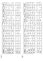
- FIG. 3 shows an example of a matrix of turbine vibration values with respect to the spindle rotational speed.
- the first horizontal row represents the main shaft rotational speed
- the second horizontal row represents the average value of the turbine vibration value at each rotational speed
- the third and subsequent horizontal lines represent the turbine vibration value at each rotational speed.
- Measurement data The spindle speed is set from 10 rpm to 90 rpm in increments of 1 rpm.
- the turbine vibration value is obtained with each acquisition number No. for each rotation speed. 1 to No. 200 items up to 200 were obtained.
- No. 1 measurement data is the oldest.
- 200 measurement data is the newest. That is, the first past predetermined period in this embodiment is No. 1 to No.
- this is a period for measuring up to 200 measurement data. Further, at each rotation number, these No. 1 to No. The average value of the measurement data up to 200 is acquired. Thus, no. 1 to No.
- the measurement data of the turbine vibration value with respect to the main shaft rotational speed up to 200 is the evaluation target data for setting the standard value and the allowable range.
- FIG. 3A for each rotation speed, all No. 1 to No. The measurement data of the turbine vibration value is acquired up to 200, and the average value is acquired.
- the measurement data of the turbine vibration value of 13 ⁇ m is newly acquired by the operation at the spindle rotational speed of 88 rpm, as shown in FIG.
- FIG. 4 shows an example of the standard value and allowable range of the turbine vibration value with respect to the main shaft rotational speed. 4 (a) and 4 (b), the horizontal axis indicates the main shaft rotation speed (rpm), the vertical axis indicates the turbine vibration value ( ⁇ m), the solid line indicates the standard value of the turbine vibration value, and the dotted line indicates the allowable range of the turbine vibration value. .
- the standard values (average values) obtained sequentially are connected to form a smooth curve, and are set continuously as shown by the solid line in FIG.
- a standard deviation is calculated from the standard value, and an allowable range indicated by a dotted line in FIG. 4 is set from the standard deviation and a weighting coefficient.
- the permissible range is also connected continuously to form a smooth curve and set continuously.
- the standard value and the standard deviation are sequentially updated based on the latest measurement data (evaluation target data), and the allowable range is also updated sequentially.
- the evaluation unit 15 evaluates the state of the device by comparing the current measurement data of each monitoring item collected by the measurement data collection unit 12 with the allowable range set by the calculation unit 14 (step SA3 in FIG. 2). ). For example, when the measurement data of the turbine vibration value with respect to the current main shaft rotational speed is the black circle in FIG. 4A, the evaluation unit 15 determines the allowable range corresponding to the main shaft rotational speed and the measurement data of the turbine vibration value. Compare In the case of FIG. 4A, since the measurement data is within the allowable range, there is no sign of abnormality. On the other hand, when the measurement data of the turbine vibration value with respect to the current spindle speed is the black circle in FIG.
- the evaluation unit 15 indicates that there is an abnormality sign because the measurement data is outside the allowable range. Judgment is made and notification is made accordingly.
- alarm setting values and trip setting values that have been used for abnormality determination from the past have been set, and if the turbine vibration value measurement data exceeds the alarm setting value or trip setting value, there is actually an abnormality. It is determined that it has occurred.
- step SA3 the allowable range is updated as needed by the calculation unit 14, and the evaluation of the device state based on the updated allowable range is performed by the evaluation unit 15.
- the time interval for updating the allowable range by the calculation unit 14 may be different from or the same as the time interval for state evaluation by the evaluation unit 15. Since it is usually difficult to think that measurement data in each monitoring item changes suddenly in a normal state, it is preferable to set the time interval for updating the allowable range sufficiently longer than the time interval for state evaluation. By doing so, it is not necessary to frequently update the allowable range, so the processing load can be reduced (for example, the initial setting is an interval of 1 second to 30 seconds, preferably an interval of 30 seconds). Data for 3 years is retained by sampling). When the time interval for updating the allowable range and the time interval for state evaluation are set to the same value, the allowable range is updated simultaneously with the measurement data measurement.
- the management since it is not necessary to individually set the update time interval of each data of the allowable range update and the state evaluation, the management is easy (for example, the initial setting is sampling at intervals of several seconds, preferably at intervals of one second. Retain data for 3 years).
- Measurement data collection unit 12 that sequentially collects and accumulates measurement data for a plurality of monitoring items for a diagnosis target device, a standard value of each monitoring item that is calculated from measurement data accumulated in measurement data collection unit 12, and The permissible range of each monitoring item is calculated based on the standard deviation of the standard value, and the standard value using the measurement data accumulated in the first past predetermined period from the present among the measurement data accumulated at any time in the measurement data collection unit 12
- a calculation unit 14 that updates the allowable range as needed, and an evaluation unit 15 that evaluates the state of the device using the allowable range calculated by the calculation unit 14, wherein the second past predetermined period is the first past predetermined period
- the calculation unit 14 sets a predetermined weight using the measurement data accumulated in the second past predetermined period from the present with respect to the standard deviation of the standard value for each monitoring item.
- a predetermined weight is set for the standard deviation of the standard value for each monitoring item, and the allowable range of each monitoring item is calculated.
- Measurement data with discontinuities can be handled by taking the standard deviation, and measurement data in the second past predetermined period that is longer than the first past predetermined period according to different states in each monitoring item Since weighting is performed based on the measurement data accumulated in a long range, the tendency of the measurement data can be given to the allowable range, and the fluctuation of the measurement data that occurs instantaneously can be excluded from the allowable range. .
- the evaluation unit 15 compares the measurement data of the current monitoring item with the allowable range of the monitoring item, and determines that there is an abnormality sign when the measurement data is outside the allowable range. Since the change in the state of the diagnosis target device is monitored using an allowable range that dynamically changes in time series, it is possible to grasp the progress of the change from the normal state to the abnormal state. Thereby, a sign of abnormality can be detected, and an appropriate measure can be taken before the abnormality occurs to prevent a malfunction. Further, since the allowable range is set using data actually acquired from the diagnosis target device, it is possible to set a range suitable for each device.
- the calculation unit 14 changes the weighting coefficient calculated by using the measurement data accumulated in the second past predetermined period from the present with respect to the standard deviation of the standard value for each monitoring item according to the magnitude of the influence of the disturbance. It may be set as follows.
- the monitoring items there are items that are easily affected by disturbance and items that are difficult to receive. Disturbances include sea conditions, sea water temperature, weather, and the like, and steam plants other than turbines can also be disturbances.
- Items that are susceptible to disturbances caused by sea conditions, sea temperature, weather, etc. include turbine vibration values and speed reducer vibration values with respect to the spindle speed, and condenser vacuum and main engine torque with respect to the main engine output. .
- items that are easily affected when a steam plant other than the turbine is disturbed include turbine internal steam pressure and turbine internal steam temperature with respect to the main engine output. Items that are easily affected by these disturbances cause fluctuations (variations) in the measurement data due to the disturbance, so the weighting coefficient for the standard deviation is set relatively large compared to items that are not easily affected by disturbances.
- a wide allowable range can be set. As a result, it is possible to suppress as much as possible from exceeding the allowable range due to a disturbance rather than an abnormality, and the evaluation unit 15 can perform a correct determination without making the fluctuation due to the disturbance abnormal.
- items that are less susceptible to disturbance among the monitored items are turbine bearing oil discharge temperature, turbine bearing pad temperature, speed reducer bearing oil discharge temperature and LO pressure with respect to main shaft rotation speed, turbine shaft position with respect to main engine output, main shaft Examples include thrust shaft position and nozzle valve lift.
- the measurement data does not fluctuate even if disturbances occur, so the allowable range can be set narrow by setting the weighting coefficient for the standard deviation small. For example, if it is necessary to evaluate changes in the value of measurement data in detail, such as when it is difficult to be affected by disturbances and it is necessary to judge that the deviation from the standard value is small, it is necessary to set a small weighting coefficient. Good. Thereby, the correct determination by the evaluation part 15 is possible. Furthermore, when weighting is omitted, an unnecessary calculation step can be omitted.
- the evaluation unit 15 determines an abnormality sign based on a change in the standard value or the allowable range updated as needed by the calculation unit 14 instead of or in addition to the evaluation method described in the above-described embodiment. It is good. For example, the standard values updated as needed by the calculation unit 14 are compared in time series, and when the tendency of the standard value set up to now and the tendency of the standard value set this time are significantly different, It is good also as detecting a sign.
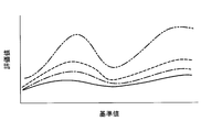
- Fig. 5 shows an example of monitoring of standard values due to aging.
- the horizontal axis of FIG. 5 is a reference value that is a monitoring item, the vertical axis is an evaluation value, the solid line is a standard value immediately after the start of operation (for example, 6 months after the start of operation), and the alternate long and short dash line is the point of 3 years after the start of operation.
- a standard value and a dotted line are standard values at the time of five years after the start of operation, and a two-dot chain line is a standard value at the time of seven years after the start of operation.
- “operation start” is the first operation start time of the device.
- the change from the standard value to the standard value at the time of 5 years from the start of operation is not greatly changed, and it is considered that the aging degradation is progressing linearly.
- the change from the standard value at the 5th year after the start of operation to the standard value at the 7th year after the start of operation is a large change compared to the previous one, and the influence of deterioration is rapidly progressing. It is expected that
- a concrete structure is not restricted to this embodiment.
- a separate notification unit such as a display, a speaker, and a message transmission unit may be provided.
- a notification unit is provided to notify when the measurement data of the current monitoring item is outside the allowable range, so that a sign of abnormality is clearly notified, and maintenance is promptly promoted for the device in which the abnormality has been notified. And take necessary measures before failure or damage occurs.
- the state diagnostic apparatus of this invention is not limited to a ship main machine turbine, The electric power generation mounted in a ship.
- Steam Turbine and Marine Floating Facility (FPSO) / FSU (Floating Storage Unit) / FSRU (Floating Storage and Regasification Unit) Widely applicable to steam turbines for power generation, etc. mounted on floating storage / regasification facilities), etc., and more generally to equipment that can be monitored for conditions. Effectively used for extraction.
- FPSO Floating Production, Storage and Shipping System
- FSU Floating Storage Unit
- FSRU Floating Storage and Regasification Unit
Landscapes
- Physics & Mathematics (AREA)
- General Physics & Mathematics (AREA)
- Engineering & Computer Science (AREA)
- Mechanical Engineering (AREA)
- General Engineering & Computer Science (AREA)
- Automation & Control Theory (AREA)
- Testing And Monitoring For Control Systems (AREA)
- Testing Of Devices, Machine Parts, Or Other Structures Thereof (AREA)
Abstract
診断対象の状態を監視して不調を予見し、経年劣化の予測が可能な状態診断装置、状態診断方法、及び状態診断プログラムを提供することを目的とする。状態診断装置(1)は、診断対象の機器についての複数の監視項目における計測データを逐次収集し、蓄積する計測データ収集部(12)と、蓄積された計測データから算出する各監視項目の標準値とその標準偏差に基づき各監視項目の許容範囲とを算出し、随時蓄積される計測データのうち現在から第一過去所定期間において蓄積された計測データを用いて標準値及び許容範囲を随時更新する算出部(14)と、算出部(14)が算出した許容範囲を用いて機器の状態を評価する評価部(15)と、を備え、算出部(14)は、監視項目毎に標準値の標準偏差に対し現在から第一過去所定期間よりも長い期間の第二過去所定期間において蓄積された計測データを用いて所定の重み付けを設定して各監視項目の許容範囲を算出する。
Description
本発明は、状態診断装置、状態診断方法、及び状態診断プログラムに関するものである。
機器の異常状態を判定する方法として、機器の使用などから異常発生と判断する閾値を設定し、この閾値を超えた場合に異常を通知する方法、また機器の状態の適否を診断する方法などが一般的に知られている。
例えば、特許文献1には、舶用主機蒸気タービンの運転監視において、タービン出力の運転データが、運転データの設計値、すなわち試運転時等稼働初期の状態データである設計データからの乖離の程度に基づいて運転状態の適否を診断することが開示されている。
例えば、特許文献1には、舶用主機蒸気タービンの運転監視において、タービン出力の運転データが、運転データの設計値、すなわち試運転時等稼働初期の状態データである設計データからの乖離の程度に基づいて運転状態の適否を診断することが開示されている。
しかしながら、従来の閾値を超えた場合に異常を報知する方法では、対象の機器の特性に依らず、予め一意に定められた閾値以下であることを監視するのみであることから、機器の状態変化を検知できず、機器の不調の兆候を見逃す場合がある。不調の予兆を見逃したまま運転を継続することで、最終的に機器停止に陥り、機器が損傷する可能性がある。
また、上記特許文献1に開示された発明では、稼働初期の状態データを基準データとして用いているため、常に初期の状態データとの比較となり経年的な変化を捉えることができず、経年劣化予測を行うことが困難である。そのため、運転状態の変化が経年的劣化によるものか、運転状態の一時的な要因(例えばオペレーションミスなど)によるものか等、いずれの外因に依る変化であるかの判断が難しいという問題があった。
また、上記特許文献1に開示された発明では、稼働初期の状態データを基準データとして用いているため、常に初期の状態データとの比較となり経年的な変化を捉えることができず、経年劣化予測を行うことが困難である。そのため、運転状態の変化が経年的劣化によるものか、運転状態の一時的な要因(例えばオペレーションミスなど)によるものか等、いずれの外因に依る変化であるかの判断が難しいという問題があった。
本発明は、このような事情に鑑みてなされたものであって、診断対象の状態を監視して不調を予見し、また経年劣化の予測が可能な状態診断装置、状態診断方法、及び状態診断プログラムを提供することを目的とする。
上記課題を解決するために、本発明の状態診断装置、状態診断方法、及び状態診断プログラムは以下の手段を採用する。
本発明の第一態様に係る状態診断装置は、診断対象の機器についての複数の監視項目における計測データを逐次収集し、蓄積する計測データ収集部と、該計測データ収集部に蓄積された前記計測データから算出する各前記監視項目の標準値と該標準値の標準偏差に基づき各前記監視項目の許容範囲とを算出し、前記計測データ収集部に随時蓄積される前記計測データのうち現在から第一過去所定期間において蓄積された前記計測データを用いて前記標準値及び前記許容範囲を随時更新する算出部と、前記算出部が算出した前記許容範囲を用いて前記機器の状態を評価する評価部と、を備え、第二過去所定期間は、前記第一過去所定期間よりも長い期間であり、前記算出部は、前記監視項目毎に前記標準値の前記標準偏差に対し現在から前記第二過去所定期間において蓄積された前記計測データを用いて所定の重み付けを設定して各前記監視項目の前記許容範囲を算出する。
本発明の第一態様に係る状態診断装置は、診断対象の機器についての複数の監視項目における計測データを逐次収集し、蓄積する計測データ収集部と、該計測データ収集部に蓄積された前記計測データから算出する各前記監視項目の標準値と該標準値の標準偏差に基づき各前記監視項目の許容範囲とを算出し、前記計測データ収集部に随時蓄積される前記計測データのうち現在から第一過去所定期間において蓄積された前記計測データを用いて前記標準値及び前記許容範囲を随時更新する算出部と、前記算出部が算出した前記許容範囲を用いて前記機器の状態を評価する評価部と、を備え、第二過去所定期間は、前記第一過去所定期間よりも長い期間であり、前記算出部は、前記監視項目毎に前記標準値の前記標準偏差に対し現在から前記第二過去所定期間において蓄積された前記計測データを用いて所定の重み付けを設定して各前記監視項目の前記許容範囲を算出する。
本態様によれば、診断対象の機器についての複数の監視項目における計測データを逐次収集し、蓄積する計測データ収集部と、該計測データ収集部に蓄積された前記計測データから算出する各前記監視項目の標準値と該標準値の標準偏差に基づき各前記監視項目の許容範囲とを算出し、前記計測データ収集部に随時蓄積される前記計測データのうち現在から第一過去所定期間において蓄積された前記計測データを用いて前記標準値及び前記許容範囲を随時更新する算出部と、前記算出部が算出した前記許容範囲を用いて前記機器の状態を評価する評価部と、を備え、第二過去所定期間は、前記第一過去所定期間よりも長い期間であり、前記算出部は、前記監視項目毎に前記標準値の前記標準偏差に対し現在から前記第二過去所定期間において蓄積された前記計測データを用いて所定の重み付けを設定して各前記監視項目の前記許容範囲を算出するため、診断対象の機器の状態変化を捉え、機器の状態異常を短・中・長期に監視できる。これにより、短期的には異常発生の検知、また中・長期的には経年変化の定量的把握を行い、中・長期的なメンテナンス及び経年劣化予測の指針とすることができる。
また、従来、正常状態であるにもかかわらず定期点検でメンテナンスが行われる事が発生する場合があったが、許容範囲内であることが確認され異常が発生しておらずメンテナンスの必要がない機器に対する点検を省略し、メンテナンスにかかるコストを最小限に抑えることができる。
また、現在から第二過去所定期間において蓄積された計測データを用いて各監視項目毎に標準値の標準偏差に所定の重み付けを設定して各監視項目の許容範囲を算出する。標準偏差をとることにより不連続点の存在する計測データを扱うことが可能である。また、各監視項目にて異なる状態に応じて第一過去所定期間よりも長い第二過去所定期間における計測データに基づき重み付けを行うことから、長いレンジで蓄積された計測データに基づくため、計測データの傾向を許容範囲に付与するとともに、瞬間的に発生する計測データの揺れを許容範囲から除外することができる。また、各監視項目毎にきめ細かく許容範囲を設定し、実情に即した状態診断を行うことができる。
また、従来、正常状態であるにもかかわらず定期点検でメンテナンスが行われる事が発生する場合があったが、許容範囲内であることが確認され異常が発生しておらずメンテナンスの必要がない機器に対する点検を省略し、メンテナンスにかかるコストを最小限に抑えることができる。
また、現在から第二過去所定期間において蓄積された計測データを用いて各監視項目毎に標準値の標準偏差に所定の重み付けを設定して各監視項目の許容範囲を算出する。標準偏差をとることにより不連続点の存在する計測データを扱うことが可能である。また、各監視項目にて異なる状態に応じて第一過去所定期間よりも長い第二過去所定期間における計測データに基づき重み付けを行うことから、長いレンジで蓄積された計測データに基づくため、計測データの傾向を許容範囲に付与するとともに、瞬間的に発生する計測データの揺れを許容範囲から除外することができる。また、各監視項目毎にきめ細かく許容範囲を設定し、実情に即した状態診断を行うことができる。
上記第一態様では、前記算出部は、前記監視項目毎に前記標準値の前記標準偏差に対し現在から前記第二過去所定期間において蓄積された前記計測データを用いて算出した重み付けの係数を外乱の影響の大きさに応じて変更して設定するとしてもよい。
本態様によれば、算出部は、監視項目毎に標準値の標準偏差に対し現在から第二過去所定期間において蓄積された計測データを用いて算出した重み付けの係数を外乱の影響の大きさに応じて変更して設定し各監視項目の許容範囲を算出するため、診断対象の機器の状態変化を捉え、機器の状態異常を短・中・長期に監視できることから、短期的には異常発生の検知、また中・長期的には経年変化の定量的把握を行い、中・長期的なメンテナンス及び経年劣化予測の指針とすることができる。
また、監視項目のうち外乱の影響の大きさに応じて重み付けの係数を変更して設定することから、外乱からの影響を受けやすい監視項目には重み付けの係数を外乱の影響を受けにくい項目と比較して相対的に大きく設定し実情に即した状態診断を行うことができる。また外乱からの影響を受けにくい監視項目に対し重み付けの係数を相対的に小さく設定することで、許容範囲を狭く設定することができる。さらに重み付けを省略する場合は、不必要な算出工程を省くことができる。また各々標準値の標準偏差をとることから、不連続点の存在する計測データを扱うことが可能である。
また、監視項目のうち外乱の影響の大きさに応じて重み付けの係数を変更して設定することから、外乱からの影響を受けやすい監視項目には重み付けの係数を外乱の影響を受けにくい項目と比較して相対的に大きく設定し実情に即した状態診断を行うことができる。また外乱からの影響を受けにくい監視項目に対し重み付けの係数を相対的に小さく設定することで、許容範囲を狭く設定することができる。さらに重み付けを省略する場合は、不必要な算出工程を省くことができる。また各々標準値の標準偏差をとることから、不連続点の存在する計測データを扱うことが可能である。
上記第一態様では、前記評価部は、現在の前記監視項目の前記計測データと、該監視項目の前記許容範囲とを比較し、該計測データが該許容範囲外であった場合に異常の兆候ありと判定するとしてもよい。
本態様によれば、評価部は、現在の監視項目の計測データと、該監視項目の許容範囲とを比較し、該計測データが該許容範囲外であった場合に異常の兆候ありと判定することから、時系列で動的に変化する許容範囲を用いて診断対象の機器の状態変化を監視するため、正常状態から異常状態へ変化するその途中経過を把握することができる。これにより、異常の兆候を検知することができ、異常が発生する前の段階で的確な措置を講じ不具合を未然に防止することができる。また、診断対象の機器から実際に取得したデータを用いて許容範囲を設定するため、各機器に適した範囲を設定することができる。
上記第一態様では、現在の前記監視項目の前記計測データが前記許容範囲外である場合に報知を行う報知部を備えるとしてもよい。
本態様によれば、現在の監視項目の計測データが許容範囲外である場合に報知を行う報知部を備えることから、明確に異常の兆候を報知することができる。これにより、異常が報知された機器についてメンテナンスを迅速に促すことができ、故障や損傷が発生する前に必要な対策を講じることができる。
本発明の第二態様に係る状態診断方法は、診断対象の機器についての複数の監視項目における計測データを逐次収集し、蓄積する計測データ収集工程と、該計測データ収集工程にて蓄積された前記計測データから算出する各前記監視項目の標準値と該標準値の標準偏差に基づき各前記監視項目の許容範囲とを算出し、前記計測データ収集工程にて随時蓄積される前記計測データのうち現在から第一過去所定期間において蓄積された前記計測データを用いて前記標準値及び前記許容範囲を随時更新する算出工程と、前記算出工程にて算出された前記許容範囲を用いて前記機器の状態を評価する評価工程と、を備え、第二過去所定期間は、前記第一過去所定期間よりも長い期間であり、前記算出工程では、前記監視項目毎に前記標準値の前記標準偏差に対し現在から前記第二過去所定期間において蓄積された前記計測データを用いて所定の重み付けを設定して各前記監視項目の前記許容範囲を算出する。
本発明の第三態様に係る状態診断プログラムは、診断対象の機器についての複数の監視項目における計測データを逐次収集し、蓄積する計測データ収集ステップと、該計測データ収集ステップにて蓄積された前記計測データから算出する各前記監視項目の標準値と該標準値の標準偏差に基づき各前記監視項目の許容範囲とを算出し、前記計測データ収集ステップにて随時蓄積される前記計測データのうち現在から第一過去所定期間において蓄積された前記計測データを用いて前記標準値及び前記許容範囲を随時更新する算出ステップと、前記算出ステップにて算出された前記許容範囲を用いて前記機器の状態を評価する評価ステップと、を備え、第二過去所定期間は、前記第一過去所定期間よりも長い期間であり、前記算出ステップでは、前記監視項目毎に前記標準値の前記標準偏差に対し現在から前記第二過去所定期間において蓄積された前記計測データを用いて所定の重み付けを設定して各前記監視項目の前記許容範囲を算出する。
本発明によれば、各機器に対応し逐次更新される許容範囲に基づき機器の状態を監視するので、異常発生を未然に防ぐことができるとともに、経年変化を把握することができる。
以下に、本発明に係る状態診断装置、状態診断方法、及び状態診断プログラムの一実施形態について、図面を参照して説明する。なお、以下の実施形態においては、本発明の状態診断装置を舶用主機タービンの状態診断に適用した場合について説明する。
図1には、本実施形態に係る状態診断装置の概略構成がブロック図にて示されている。
図1に示されるように、状態診断装置1は、計測データ収集部12と、算出部14と、評価部15とを主な構成として備えている。
図1に示されるように、状態診断装置1は、計測データ収集部12と、算出部14と、評価部15とを主な構成として備えている。
計測データ収集部12には、舶用主機タービンの各部に取り付けられたセンサから計測データがリアルタイムで送信される。これにより、計測データ収集部12には、各監視項目における計測データ、つまり、主軸回転数、主機出力、タービン軸受温度、タービン振動値、タービン軸位置、タービン内部蒸気温度、タービン内部蒸気圧力などの計測データが逐次蓄積される。
算出部14は、各監視項目の計測データを用いて、各監視項目の許容範囲を設定する。具体的には、算出部14は、各監視項目における計測データの標準値と標準偏差と重み付けの係数とから許容範囲を設定する。
ここで、標準値とは、所定の期間における計測データの基準となる値であり、本実施形態では所定の期間における計測データの平均値としている。
また、計測データが線型である場合は、標準値に対し所定の値を減算した値から標準値に対し所定の値を加算した値までの範囲を許容範囲とすればよい。しかし、特に舶用主機タービンの場合は、港湾における航行と外洋における航行との切り替えなどにより不連続点が生じ、線型とならない。そこで標準値の標準偏差をとることにより、計測データが不連続な値であっても適切な許容範囲を設定することができる。
さらに、重み付けは、各監視項目に対応する係数を付与するものであり、外乱など標準偏差のみでは現れない要因に対し重みを付けるものである。
例えば、算出部14は、各監視項目に対応する重み付けの係数αを有しており、重み付けの係数αに標準偏差σを乗じた値を平均値μから減算した値を許容範囲の下限値に、係数αに標準偏差σを乗じた値を平均値μに加算した値を許容範囲の上限値に設定する。
ここで、標準値とは、所定の期間における計測データの基準となる値であり、本実施形態では所定の期間における計測データの平均値としている。
また、計測データが線型である場合は、標準値に対し所定の値を減算した値から標準値に対し所定の値を加算した値までの範囲を許容範囲とすればよい。しかし、特に舶用主機タービンの場合は、港湾における航行と外洋における航行との切り替えなどにより不連続点が生じ、線型とならない。そこで標準値の標準偏差をとることにより、計測データが不連続な値であっても適切な許容範囲を設定することができる。
さらに、重み付けは、各監視項目に対応する係数を付与するものであり、外乱など標準偏差のみでは現れない要因に対し重みを付けるものである。
例えば、算出部14は、各監視項目に対応する重み付けの係数αを有しており、重み付けの係数αに標準偏差σを乗じた値を平均値μから減算した値を許容範囲の下限値に、係数αに標準偏差σを乗じた値を平均値μに加算した値を許容範囲の上限値に設定する。
上記許容範囲を式で表わすと以下の通りである。
下限値:μ-α*σ
上限値:μ+α*σ
下限値:μ-α*σ
上限値:μ+α*σ
また、算出部14は、計測データ収集部12によって収集された現在から第一過去所定期間における計測データを用いて標準値及び標準偏差を更新する。また現在から第二過去所定期間における計測データを用いて重み付けの係数を更新する。そしてこれらの値を用いて所定の時間間隔で許容範囲を更新する。これにより、許容範囲は、新しい計測データを常に取り入れた形で随時更新されることとなる。
ここで、第一過去所定期間は、例えば一度の航海期間(一の航路を運航するのに要する期間)であるとする。これにより、停泊、港湾航行、外洋航行、港湾航行、停泊、と、タービンの低負荷から高負荷まで、換言すると回転数の低回転数から高回転数まで、数値を網羅するようにサンプリングすることが可能であるため、適切に許容範囲を更新することができる。
また第二過去所定期間は、第一過去所定期間よりも長い期間であり、例えば少なくとも1年以上、さらに好適には1年程度が設定される。季節性のある外乱(気温・海水温・海象など)が機器に及ぼす影響は、この外乱の周年変化に伴い変化する。そこで、第二過去所定期間に少なくとも1年以上の期間を設定することにより、季節性のある外乱の影響を含む計測データを用いて重み付けの係数を更新するものとする。このように、季節性の変化による影響を含めた計測データによって、適切に許容範囲を更新することができる。但し、第二過去所定期間を2年以上など長く設定すると、経年劣化を含む許容範囲となるため、1年程度が好適である。
このように設定された第二過去所定期間における計測データに基づき重み付けの係数の更新を行い、許容範囲が更新される。第二過去所定期間における計測データを用いた重み付けにより、気温・海水温・海象などの季節性のある外乱の影響を受けた現在の計測データ(本来、異常と判定すべきではない計測データ)が異常と判定されないような許容範囲が設定される。
このように設定された第二過去所定期間における計測データに基づき重み付けの係数の更新を行い、許容範囲が更新される。第二過去所定期間における計測データを用いた重み付けにより、気温・海水温・海象などの季節性のある外乱の影響を受けた現在の計測データ(本来、異常と判定すべきではない計測データ)が異常と判定されないような許容範囲が設定される。
評価部15は、算出部14によって設定された各監視項目の許容範囲を用いて、機器の状態評価を行う。具体的には、評価部15は、現在の監視項目の計測データと、該計測データが該当する許容範囲とを比較し、現在の計測データが許容範囲外であった場合に異常の兆候を検知したとして、その旨を作業員に報知する。
状態診断装置1は、例えば、CPU(Central Processing Unit)、RAM(Random Access Memory)、ROM(Read Only Memory)、及びコンピュータ読み取り可能な記憶媒体等から構成されている。そして、各種機能を実現するための一連の処理は、一例として、プログラムの形式で記憶媒体等に記憶されており、このプログラムをCPUがRAM等に読み出して、情報の加工・演算処理を実行することにより、各種機能が実現される。なお、プログラムは、ROMやその他の記憶媒体に予めインストールしておく形態や、コンピュータ読み取り可能な記憶媒体に記憶された状態で提供される形態、有線又は無線による通信手段を介して配信される形態等が適用されてもよい。コンピュータ読み取り可能な記憶媒体とは、磁気ディスク、光磁気ディスク、CD-ROM、DVD-ROM、半導体メモリ等である。
次に、上記構成を備える本実施形態に係る状態診断装置1の作用について図2を参照して説明する。
まず、診断対象の機器、ここでは主機または主機の周辺に取り付けられた各種センサによって検出された計測データが計測データ収集部12に収集される(図2のステップSA1)。このようにして収集された各計測データは、計測データ収集部12において、その計測データが計測された時間情報が対応付けられて監視項目毎に格納される。
まず、診断対象の機器、ここでは主機または主機の周辺に取り付けられた各種センサによって検出された計測データが計測データ収集部12に収集される(図2のステップSA1)。このようにして収集された各計測データは、計測データ収集部12において、その計測データが計測された時間情報が対応付けられて監視項目毎に格納される。
続いて、算出部14において、監視項目毎の計測データの平均値である標準値、標準偏差及び重み付けの係数が算出され、これらの値を用いて監視項目毎に許容範囲が設定される(図2のステップSA2)。これにより、各監視項目について許容範囲が設定される。
図3に、主軸回転数に対するタービン振動値のマトリクスの一例を示す。図3(a)及び(b)において、横1行目は主軸回転数、横2行目は各回転数におけるタービン振動値の平均値、横3行目以降は各回転数におけるタービン振動値の計測データである。主軸回転数は、10rpmから90rpmまで1rpm刻みで設定される。タービン振動値は、各回転数に対してそれぞれ取得番号No.1からNo.200まで200項取得され、No.1の計測データが最も古く、No.200の計測データが最も新しい。すなわち、本実施形態における第一過去所定期間は、No.1からNo.200までの計測データを計測する期間であるといえる。また、各回転数において、これらNo.1からNo.200までの計測データの平均値が取得される。このように、No.1からNo.200までの主軸回転数に対するタービン振動値の計測データが、標準値及び許容範囲を設定するための評価対象データとなる。
図3(a)では、それぞれの回転数に対し、全てNo.1からNo.200までタービン振動値の計測データが取得され、平均値が取得された状態である。
ここで、主軸回転数88rpmの運転にて新たにタービン振動値13μmの計測データが取得されると、図3(b)に示されるようにNo.1の計測データが評価対象データから削除され(計測データ収集部12には蓄積(保存)されたままである)、No.2のデータからNo.200のデータがそれぞれNo.1からNo.199の欄に移動される。そして、最新のデータ13μmがNo.200に入力され、新たなNo.1からNo.200のデータにより平均値が11.1μmに更新される。
図3(a)では、それぞれの回転数に対し、全てNo.1からNo.200までタービン振動値の計測データが取得され、平均値が取得された状態である。
ここで、主軸回転数88rpmの運転にて新たにタービン振動値13μmの計測データが取得されると、図3(b)に示されるようにNo.1の計測データが評価対象データから削除され(計測データ収集部12には蓄積(保存)されたままである)、No.2のデータからNo.200のデータがそれぞれNo.1からNo.199の欄に移動される。そして、最新のデータ13μmがNo.200に入力され、新たなNo.1からNo.200のデータにより平均値が11.1μmに更新される。
図4に、主軸回転数に対するタービン振動値の標準値及び許容範囲の一例を示す。図4(a)及び(b)において、横軸は主軸回転数(rpm)、縦軸はタービン振動値(μm)、実線はタービン振動値の標準値、点線はタービン振動値の許容範囲を示す。
図3に示されるように、逐次求められた標準値(平均値)は、滑らかな曲線となるように繋ぎ合わせられ、図4の実線に示されるように連続的に設定される。
この標準値から標準偏差が算出され、標準偏差及び重み付けの係数から、図4の点線に示される許容範囲が設定される。許容範囲についても、滑らかな曲線となるように繋ぎ合わせられ、連続的に設定される。
標準値および標準偏差は、図3に示されるように最新の計測データ(評価対象データ)に基づき逐次更新され、許容範囲も逐次更新される。
図3に示されるように、逐次求められた標準値(平均値)は、滑らかな曲線となるように繋ぎ合わせられ、図4の実線に示されるように連続的に設定される。
この標準値から標準偏差が算出され、標準偏差及び重み付けの係数から、図4の点線に示される許容範囲が設定される。許容範囲についても、滑らかな曲線となるように繋ぎ合わせられ、連続的に設定される。
標準値および標準偏差は、図3に示されるように最新の計測データ(評価対象データ)に基づき逐次更新され、許容範囲も逐次更新される。
評価部15は、計測データ収集部12に収集される各監視項目の現在の計測データを算出部14によって設定された許容範囲と比較することにより、機器の状態を評価する(図2のステップSA3)。例えば、現在の主軸回転数に対するタービン振動値の計測データが図4(a)の黒丸であった場合には、評価部15は、主軸回転数に対応する許容範囲とタービン振動値の計測データとを比較する。図4(a)の場合、計測データは許容範囲内であることから、異常の兆候は無いとされる。
一方、現在の主軸回転数に対するタービン振動値の計測データが図4(b)の黒丸であった場合には、評価部15は、計測データが許容範囲外であることから、異常の兆候ありと判断して、その旨を報知する。
また、さらに従来から異常判定に用いられているアラーム設定値及びトリップ設定値が設定されており、タービン振動値の計測データがアラーム設定値またはトリップ設定値を超えた場合には、実際に異常が発生していると判定される。
一方、現在の主軸回転数に対するタービン振動値の計測データが図4(b)の黒丸であった場合には、評価部15は、計測データが許容範囲外であることから、異常の兆候ありと判断して、その旨を報知する。
また、さらに従来から異常判定に用いられているアラーム設定値及びトリップ設定値が設定されており、タービン振動値の計測データがアラーム設定値またはトリップ設定値を超えた場合には、実際に異常が発生していると判定される。
そして、上記ステップSA1からステップSA3の処理が繰り返し行われることにより、許容範囲が算出部14によって随時更新されるとともに、更新される許容範囲に基づく機器の状態評価が評価部15によって行われる。
なお、算出部14による許容範囲の更新の時間間隔は、評価部15による状態評価の時間間隔と異なっていてもよいし、同じであってもよい。
正常な状態において、各監視項目における計測データが急激に変化することは通常考えにくいため、許容範囲の更新の時間間隔を、状態評価の時間間隔に比べて、十分長く設定することが好ましい。このようにすることで、許容範囲の更新を頻繁に行わなくてもよいので、処理負担を軽減することができる(例えば、初期設定は1秒以上30秒以下の間隔、好適には30秒間隔のサンプリングで3年間分のデータを保持)。
また、許容範囲の更新の時間間隔及び状態評価の時間間隔を同じ値とする場合は、計測データの計測と同時に許容範囲が更新されることとなる。この場合、許容範囲の更新及び状態評価の各データの更新時間間隔を個別に設定する必要がないため、管理が容易である(例えば、初期設定は数秒間隔、好適には1秒間隔のサンプリングで3年間分のデータを保持)。
正常な状態において、各監視項目における計測データが急激に変化することは通常考えにくいため、許容範囲の更新の時間間隔を、状態評価の時間間隔に比べて、十分長く設定することが好ましい。このようにすることで、許容範囲の更新を頻繁に行わなくてもよいので、処理負担を軽減することができる(例えば、初期設定は1秒以上30秒以下の間隔、好適には30秒間隔のサンプリングで3年間分のデータを保持)。
また、許容範囲の更新の時間間隔及び状態評価の時間間隔を同じ値とする場合は、計測データの計測と同時に許容範囲が更新されることとなる。この場合、許容範囲の更新及び状態評価の各データの更新時間間隔を個別に設定する必要がないため、管理が容易である(例えば、初期設定は数秒間隔、好適には1秒間隔のサンプリングで3年間分のデータを保持)。
以上説明したように、本実施形態に係る状態診断装置1によれば、以下の作用効果を奏する。
診断対象の機器についての複数の監視項目における計測データを逐次収集し、蓄積する計測データ収集部12と、該計測データ収集部12に蓄積された計測データから算出する各監視項目の標準値と該標準値の標準偏差に基づき各監視項目の許容範囲とを算出し、計測データ収集部12に随時蓄積される計測データのうち現在から第一過去所定期間において蓄積された計測データを用いて標準値及び許容範囲を随時更新する算出部14と、算出部14が算出した許容範囲を用いて機器の状態を評価する評価部15と、を備え、第二過去所定期間は、前記第一過去所定期間よりも長い期間であり、算出部14は、監視項目毎に標準値の標準偏差に対し現在から第二過去所定期間において蓄積された計測データを用いて所定の重み付けを設定して各監視項目の許容範囲を算出するため、診断対象の機器の状態変化を捉え、機器の状態異常を短・中・長期に監視できることから、短期的には異常発生の検知、また中・長期的には経年変化の定量的把握を行い、中・長期的なメンテナンス及び経年劣化予測の指針とすることができる。
診断対象の機器についての複数の監視項目における計測データを逐次収集し、蓄積する計測データ収集部12と、該計測データ収集部12に蓄積された計測データから算出する各監視項目の標準値と該標準値の標準偏差に基づき各監視項目の許容範囲とを算出し、計測データ収集部12に随時蓄積される計測データのうち現在から第一過去所定期間において蓄積された計測データを用いて標準値及び許容範囲を随時更新する算出部14と、算出部14が算出した許容範囲を用いて機器の状態を評価する評価部15と、を備え、第二過去所定期間は、前記第一過去所定期間よりも長い期間であり、算出部14は、監視項目毎に標準値の標準偏差に対し現在から第二過去所定期間において蓄積された計測データを用いて所定の重み付けを設定して各監視項目の許容範囲を算出するため、診断対象の機器の状態変化を捉え、機器の状態異常を短・中・長期に監視できることから、短期的には異常発生の検知、また中・長期的には経年変化の定量的把握を行い、中・長期的なメンテナンス及び経年劣化予測の指針とすることができる。
また、従来正常状態であるにもかかわらず定期点検でメンテナンスが行われる事が発生する場合があったが、許容範囲内であることが確認され異常が発生しておらずメンテナンスの必要がない機器に対する点検を省略し、メンテナンスにかかるコストを最小限に抑えることができる。
また、現在から第二過去所定期間において蓄積された計測データを用いて各監視項目毎に標準値の標準偏差に所定の重み付けを設定して各監視項目の許容範囲を算出する。標準偏差をとることにより不連続点の存在する計測データを扱うことが可能であり、また、各監視項目にて異なる状態に応じて第一過去所定期間よりも長い第二過去所定期間における計測データに基づき重み付けを行うことから、長いレンジで蓄積された計測データに基づくため、計測データの傾向を許容範囲に付与するとともに、瞬間的に発生する計測データの揺れを許容範囲から除外することができる。また、各監視項目毎にきめ細かく許容範囲を設定し、実情に即した状態診断を行うことができる。
また、評価部15は、現在の監視項目の計測データと、該監視項目の許容範囲とを比較し、該計測データが該許容範囲外であった場合に異常の兆候ありと判定することから、時系列で動的に変化する許容範囲を用いて診断対象の機器の状態変化を監視するため、正常状態から異常状態へ変化するその途中経過を把握することができる。これにより、異常の兆候を検知することができ、異常が発生する前の段階で的確な措置を講じ不具合を未然に防止することができる。また、診断対象の機器から実際に取得したデータを用いて許容範囲を設定するため、各機器に適した範囲を設定することができる。
なお、算出部14は、監視項目毎に標準値の標準偏差に対し現在から第二過去所定期間において蓄積された計測データを用いて算出した重み付けの係数を外乱の影響の大きさに応じて変更して設定するとしてもよい。
監視項目のうち、外乱の影響を受けやすい項目と受けにくい項目とが存在する。また外乱とは、海象、海水温、気象などであり、さらにタービン以外の蒸気プラントも外乱となり得る。
監視項目のうち、外乱の影響を受けやすい項目と受けにくい項目とが存在する。また外乱とは、海象、海水温、気象などであり、さらにタービン以外の蒸気プラントも外乱となり得る。
海象、海水温、気象などを外乱とした場合に影響を受けやすい項目としては、主軸回転数に対するタービン振動値および減速装置振動値、及び主機出力に対する復水器真空度および主機トルクなどが挙げられる。
またタービン以外の蒸気プラントを外乱とした場合に影響を受けやすい項目としては、主機出力に対するタービン内部蒸気圧力およびタービン内部蒸気温度などが挙げられる。
これらの外乱の影響を受けやすい項目は、外乱により計測データに揺れ(ばらつき)が生じるため、標準偏差に対する重み付けの係数を外乱の影響を受けにくい項目と比較して相対的に大きく設定することで許容範囲を広く設定することができる。これにより、異常ではなく外乱によって許容範囲を超えることを極力抑えることができ、外乱による揺れを異常とせず評価部15による正しい判定が可能である。
またタービン以外の蒸気プラントを外乱とした場合に影響を受けやすい項目としては、主機出力に対するタービン内部蒸気圧力およびタービン内部蒸気温度などが挙げられる。
これらの外乱の影響を受けやすい項目は、外乱により計測データに揺れ(ばらつき)が生じるため、標準偏差に対する重み付けの係数を外乱の影響を受けにくい項目と比較して相対的に大きく設定することで許容範囲を広く設定することができる。これにより、異常ではなく外乱によって許容範囲を超えることを極力抑えることができ、外乱による揺れを異常とせず評価部15による正しい判定が可能である。
一方、監視項目のうち外乱の影響を受けにくい項目には、主軸回転数に対するタービン軸受排油温度、タービン軸受パッド温度、減速装置軸受排油温度およびLO圧力、及び主機出力に対するタービン軸位置、主スラスト軸位置およびノズル弁リフトなどが挙げられる。
これら外乱の影響を受けにくい項目は、外乱が生じても計測データの揺れはほぼ生じないため、標準偏差に対する重み付けの係数を小さく設定することで許容範囲を狭く設定することができる。例えば、外乱の影響を受けにくく、標準値からの乖離が小さくとも異常と判定する必要があるなど、計測データの値の変化を詳細に評価する必要がある場合には、重み付けの係数を小さく設定するとよい。これにより、評価部15による正しい判定が可能である。さらに、重み付けを省略する場合には、不必要な算出工程を省くことができる。
これら外乱の影響を受けにくい項目は、外乱が生じても計測データの揺れはほぼ生じないため、標準偏差に対する重み付けの係数を小さく設定することで許容範囲を狭く設定することができる。例えば、外乱の影響を受けにくく、標準値からの乖離が小さくとも異常と判定する必要があるなど、計測データの値の変化を詳細に評価する必要がある場合には、重み付けの係数を小さく設定するとよい。これにより、評価部15による正しい判定が可能である。さらに、重み付けを省略する場合には、不必要な算出工程を省くことができる。
また、評価部15は、上述した実施形態で説明した評価方法に代えて、または、加えて、算出部14によって随時更新される標準値または許容範囲の変化に基づいて異常の兆候を判定することとしてもよい。
例えば、算出部14により随時更新される標準値を時系列で比較していき、今まで設定されてきた標準値の傾向と今回設定された標準値の傾向とが著しく異なっていた場合に異常の兆候を検知することとしてもよい。
例えば、算出部14により随時更新される標準値を時系列で比較していき、今まで設定されてきた標準値の傾向と今回設定された標準値の傾向とが著しく異なっていた場合に異常の兆候を検知することとしてもよい。
図5には、経年変化による標準値の監視例がグラフに示されている。図5の横軸は監視項目である基準値、縦軸は評価値であり、実線は運転開始直後(例えば運転開始後6か月時点)の標準値、一点鎖線は運転開始後3年時点の標準値、点線は運転開始後5年時点の標準値、二点鎖線は運転開始後7年時点の標準値である。ここで、「運転開始」とは、機器の初めての運転開始時であるとする。
図5に示されるように、運転開始直後の計測データを基にした基準値に対する評価値の標準値から運転開始後3年時点での標準値への変化、及び運転開始後3年時点での標準値から運転開始後5年時点での標準値への変化は、いずれも大きな変化はなく、経年劣化は線型的に進行しているものと考えられる。しかし、運転開始後5年時点での標準値から運転開始後7年時点での標準値へはその変化がそれまでと比較して大きな変化となっており、劣化による影響が急激に進行していることが予想される。
このように、標準値に時系列的評価を加えることで、機器の経年変化及び劣化予測が可能となり、機器の損傷に至る前に次回の定期点検での詳細点検の実施や部品交換の推奨など適切な保守指針を策定することができる。
以上、本発明の実施形態について図面を参照して詳述してきたが、具体的な構成はこの実施形態に限られるものではない。
たとえば、上述した各実施形態においては、評価部15が異常の兆候ありと判断すると、その旨を作業員へ報知するとしたが、別途ディスプレイ、スピーカー、メッセージ送信手段などの報知部を設けるとしてもよい。これにより、現在の監視項目の計測データが許容範囲外である場合に報知を行う報知部を備えることから、明確に異常の兆候を報知し、異常が報知された機器についてメンテナンスを迅速に促すことができ、故障や損傷が発生する前に必要な対策を講じることができる。
たとえば、上述した各実施形態においては、評価部15が異常の兆候ありと判断すると、その旨を作業員へ報知するとしたが、別途ディスプレイ、スピーカー、メッセージ送信手段などの報知部を設けるとしてもよい。これにより、現在の監視項目の計測データが許容範囲外である場合に報知を行う報知部を備えることから、明確に異常の兆候を報知し、異常が報知された機器についてメンテナンスを迅速に促すことができ、故障や損傷が発生する前に必要な対策を講じることができる。
また、上述した実施形態では、舶用主機タービンに本発明の状態診断装置を適用した場合について説明したが、本発明の状態診断装置は、舶用主機タービンに限定されることなく、船舶に搭載する発電用蒸気タービン、及び海洋浮体設備(FPSO(Floating Production, Storage and Off-loading system:浮体式生産・貯蔵・出荷設備)/FSU(Floating Storage Unit:浮体式貯蔵設備)/FSRU(Floating Storage and Regasification Unit:浮体式貯蔵・再ガス化設備)など)に搭載する発電用蒸気タービン等、さらには一般的に状態監視が可能な機器等に広く適用可能であり、これらの余寿命予測や異常発生の事前抽出等に有効に活用される。
1 状態診断装置
12 計測データ収集部
14 算出部
15 評価部
12 計測データ収集部
14 算出部
15 評価部
Claims (6)
- 診断対象の機器についての複数の監視項目における計測データを逐次収集し、蓄積する計測データ収集部と、
該計測データ収集部に蓄積された前記計測データから算出する各前記監視項目の標準値と該標準値の標準偏差に基づき各前記監視項目の許容範囲とを算出し、前記計測データ収集部に随時蓄積される前記計測データのうち現在から第一過去所定期間において蓄積された前記計測データを用いて前記標準値及び前記許容範囲を随時更新する算出部と、
前記算出部が算出した前記許容範囲を用いて前記機器の状態を評価する評価部と、
を備え、
第二過去所定期間は、前記第一過去所定期間よりも長い期間であり、
前記算出部は、前記監視項目毎に前記標準値の前記標準偏差に対し現在から前記第二過去所定期間において蓄積された前記計測データを用いて所定の重み付けを設定して各前記監視項目の前記許容範囲を算出する状態診断装置。 - 前記算出部は、前記監視項目毎に前記標準値の前記標準偏差に対し現在から前記第二過去所定期間において蓄積された前記計測データを用いて算出した重み付けの係数を外乱の影響の大きさに応じて変更して設定し各前記監視項目の前記許容範囲を算出する請求項1に記載の状態診断装置。
- 前記評価部は、現在の前記監視項目の前記計測データと、該監視項目の前記許容範囲とを比較し、該計測データが該許容範囲外であった場合に異常の兆候ありと判定する請求項1または請求項2に記載の状態診断装置。
- 現在の前記監視項目の前記計測データが前記許容範囲外である場合に報知を行う報知部を備える請求項3に記載の状態診断装置。
- 診断対象の機器についての複数の監視項目における計測データを逐次収集し、蓄積する計測データ収集工程と、
該計測データ収集工程にて蓄積された前記計測データから算出する各前記監視項目の標準値と該標準値の標準偏差に基づき各前記監視項目の許容範囲とを算出し、前記計測データ収集工程にて随時蓄積される前記計測データのうち現在から第一過去所定期間において蓄積された前記計測データを用いて前記標準値及び前記許容範囲を随時更新する算出工程と、
前記算出工程にて算出された前記許容範囲を用いて前記機器の状態を評価する評価工程と、
を備え、
第二過去所定期間は、前記第一過去所定期間よりも長い期間であり、
前記算出工程では、前記監視項目毎に前記標準値の前記標準偏差に対し現在から前記第二過去所定期間において蓄積された前記計測データを用いて所定の重み付けを設定して各前記監視項目の前記許容範囲を算出する状態診断方法。 - 診断対象の機器についての複数の監視項目における計測データを逐次収集し、蓄積する計測データ収集ステップと、
該計測データ収集ステップにて蓄積された前記計測データから算出する各前記監視項目の標準値と該標準値の標準偏差に基づき各前記監視項目の許容範囲とを算出し、前記計測データ収集ステップにて随時蓄積される前記計測データのうち現在から第一過去所定期間において蓄積された前記計測データを用いて前記標準値及び前記許容範囲を随時更新する算出ステップと、
前記算出ステップにて算出された前記許容範囲を用いて前記機器の状態を評価する評価ステップと、
を備え、
第二過去所定期間は、前記第一過去所定期間よりも長い期間であり、
前記算出ステップでは、前記監視項目毎に前記標準値の前記標準偏差に対し現在から前記第二過去所定期間において蓄積された前記計測データを用いて所定の重み付けを設定して各前記監視項目の前記許容範囲を算出する状態診断プログラム。
Priority Applications (3)
| Application Number | Priority Date | Filing Date | Title |
|---|---|---|---|
| CN201980003698.3A CN110998275B (zh) | 2018-02-27 | 2019-01-31 | 状态诊断装置、状态诊断方法及存储介质 |
| EP19760788.0A EP3671175B1 (en) | 2018-02-27 | 2019-01-31 | Condition diagnosing device, condition diagnosing method, and condition diagnosing program |
| KR1020207001691A KR102105297B1 (ko) | 2018-02-27 | 2019-01-31 | 상태 진단 장치, 상태 진단 방법, 및 상태 진단 프로그램 |
Applications Claiming Priority (2)
| Application Number | Priority Date | Filing Date | Title |
|---|---|---|---|
| JP2018032775A JP6790006B2 (ja) | 2018-02-27 | 2018-02-27 | 状態診断装置、状態診断方法、及び状態診断プログラム |
| JP2018-032775 | 2018-02-27 |
Publications (1)
| Publication Number | Publication Date |
|---|---|
| WO2019167537A1 true WO2019167537A1 (ja) | 2019-09-06 |
Family
ID=67805316
Family Applications (1)
| Application Number | Title | Priority Date | Filing Date |
|---|---|---|---|
| PCT/JP2019/003409 Ceased WO2019167537A1 (ja) | 2018-02-27 | 2019-01-31 | 状態診断装置、状態診断方法、及び状態診断プログラム |
Country Status (5)
| Country | Link |
|---|---|
| EP (1) | EP3671175B1 (ja) |
| JP (1) | JP6790006B2 (ja) |
| KR (1) | KR102105297B1 (ja) |
| CN (1) | CN110998275B (ja) |
| WO (1) | WO2019167537A1 (ja) |
Cited By (1)
| Publication number | Priority date | Publication date | Assignee | Title |
|---|---|---|---|---|
| CN113375952A (zh) * | 2021-06-08 | 2021-09-10 | 上海衡拓船舶设备有限公司 | 一种减摇鳍装置故障诊断及健康预报系统 |
Families Citing this family (4)
| Publication number | Priority date | Publication date | Assignee | Title |
|---|---|---|---|---|
| EP4092401B1 (en) * | 2020-01-16 | 2025-07-30 | A&D Company, Limited | Moisture meter, state diagnosis method for moisture meter, and program |
| JP7546502B2 (ja) * | 2021-03-05 | 2024-09-06 | 住友重機械工業株式会社 | 状態診断システム |
| JP7550093B2 (ja) * | 2021-03-29 | 2024-09-12 | 株式会社日立産機システム | 監視装置及び方法 |
| KR102714738B1 (ko) * | 2022-07-15 | 2024-10-11 | 한국서부발전 주식회사 | 진동 데이터를 활용한 탄종별 igcc 석탄미분건조장치의 보호 시스템 |
Citations (6)
| Publication number | Priority date | Publication date | Assignee | Title |
|---|---|---|---|---|
| JPH102843A (ja) * | 1996-06-14 | 1998-01-06 | Syst Sogo Kaihatsu Kk | 製造工程管理システム |
| JP2010175446A (ja) * | 2009-01-30 | 2010-08-12 | Mitsubishi Heavy Ind Ltd | 状態診断装置 |
| JP2010203929A (ja) * | 2009-03-04 | 2010-09-16 | Jfe Steel Corp | 機械設備における異常診断システム |
| JP4669061B1 (ja) | 2009-10-19 | 2011-04-13 | 川崎重工業株式会社 | 舶用主機蒸気タービンの運転監視・診断方法 |
| JP2016110594A (ja) * | 2014-12-08 | 2016-06-20 | 株式会社東芝 | プラント監視装置、プラント監視方法、およびプログラム |
| JP2017157072A (ja) * | 2016-03-03 | 2017-09-07 | 株式会社日立製作所 | 異常検出装置、系統安定度監視装置、及びそのシステム |
Family Cites Families (8)
| Publication number | Priority date | Publication date | Assignee | Title |
|---|---|---|---|---|
| JPH07175515A (ja) * | 1993-12-17 | 1995-07-14 | Kobe Steel Ltd | 機械設備及びローラミルの異常検出方法,安定度算出方法及び運転制御方法 |
| JP5297272B2 (ja) * | 2009-06-11 | 2013-09-25 | 株式会社日立製作所 | 装置異常監視方法及びシステム |
| CN101995290B (zh) * | 2009-08-28 | 2013-04-24 | 威能极公司 | 风力发电机振动监测的方法和系统 |
| CN102713777B (zh) * | 2010-01-22 | 2015-07-01 | 株式会社日立制作所 | 诊断装置及诊断方法 |
| CN102662321B (zh) * | 2012-03-23 | 2014-03-12 | 清华大学 | 一种主元分析监控模型的在线更新方法 |
| GB201322062D0 (en) * | 2013-12-13 | 2014-01-29 | Optimized Systems And Solutions Ltd | System abnormalities |
| JP2017088314A (ja) * | 2015-11-10 | 2017-05-25 | 株式会社日立ビルシステム | 機器診断装置および機器診断方法、並びに機器診断システム |
| CN106969266B (zh) * | 2017-04-13 | 2019-02-22 | 浙江大学 | 城市供水管网的管道压力监测设备在线运行状态诊断方法 |
-
2018
- 2018-02-27 JP JP2018032775A patent/JP6790006B2/ja active Active
-
2019
- 2019-01-31 EP EP19760788.0A patent/EP3671175B1/en active Active
- 2019-01-31 KR KR1020207001691A patent/KR102105297B1/ko active Active
- 2019-01-31 WO PCT/JP2019/003409 patent/WO2019167537A1/ja not_active Ceased
- 2019-01-31 CN CN201980003698.3A patent/CN110998275B/zh active Active
Patent Citations (6)
| Publication number | Priority date | Publication date | Assignee | Title |
|---|---|---|---|---|
| JPH102843A (ja) * | 1996-06-14 | 1998-01-06 | Syst Sogo Kaihatsu Kk | 製造工程管理システム |
| JP2010175446A (ja) * | 2009-01-30 | 2010-08-12 | Mitsubishi Heavy Ind Ltd | 状態診断装置 |
| JP2010203929A (ja) * | 2009-03-04 | 2010-09-16 | Jfe Steel Corp | 機械設備における異常診断システム |
| JP4669061B1 (ja) | 2009-10-19 | 2011-04-13 | 川崎重工業株式会社 | 舶用主機蒸気タービンの運転監視・診断方法 |
| JP2016110594A (ja) * | 2014-12-08 | 2016-06-20 | 株式会社東芝 | プラント監視装置、プラント監視方法、およびプログラム |
| JP2017157072A (ja) * | 2016-03-03 | 2017-09-07 | 株式会社日立製作所 | 異常検出装置、系統安定度監視装置、及びそのシステム |
Non-Patent Citations (1)
| Title |
|---|
| See also references of EP3671175A4 |
Cited By (2)
| Publication number | Priority date | Publication date | Assignee | Title |
|---|---|---|---|---|
| CN113375952A (zh) * | 2021-06-08 | 2021-09-10 | 上海衡拓船舶设备有限公司 | 一种减摇鳍装置故障诊断及健康预报系统 |
| CN113375952B (zh) * | 2021-06-08 | 2024-03-19 | 上海衡拓船舶设备有限公司 | 一种减摇鳍装置故障诊断及健康预报系统 |
Also Published As
| Publication number | Publication date |
|---|---|
| EP3671175A1 (en) | 2020-06-24 |
| KR20200012019A (ko) | 2020-02-04 |
| CN110998275B (zh) | 2021-01-22 |
| CN110998275A (zh) | 2020-04-10 |
| EP3671175B1 (en) | 2022-08-17 |
| KR102105297B1 (ko) | 2020-04-28 |
| JP6790006B2 (ja) | 2020-11-25 |
| JP2019148474A (ja) | 2019-09-05 |
| EP3671175A4 (en) | 2020-12-16 |
Similar Documents
| Publication | Publication Date | Title |
|---|---|---|
| JP6790006B2 (ja) | 状態診断装置、状態診断方法、及び状態診断プログラム | |
| JP3609982B2 (ja) | 故障診断方法及びその装置 | |
| EP2585716B1 (en) | A method for performing condition monitoring in a wind farm | |
| Igba et al. | Analysing RMS and peak values of vibration signals for condition monitoring of wind turbine gearboxes | |
| KR102040179B1 (ko) | 제조 설비의 이상 감지 및 진단 방법 | |
| US20170350789A1 (en) | Operating Wind Motors and Determining their Remaining Useful Life | |
| CN108780025A (zh) | 状态监视系统和风力发电装置 | |
| JP2931187B2 (ja) | ポンプ劣化診断システム | |
| WO2014096014A1 (en) | Method of monitoring the condition of a wind turbine | |
| CN108700491B (zh) | 涡轮机系统中的轴承碳化故障检测 | |
| US7249287B2 (en) | Methods and apparatus for providing alarm notification | |
| JP2010175446A (ja) | 状態診断装置 | |
| KR101399488B1 (ko) | 원전 저널 베어링 온라인 결함 진단 시스템 | |
| Ma et al. | Research on condition monitoring of bearing health using vibration data | |
| CN116821748A (zh) | 一种船舶轴系推进能效监测系统故障检测方法及模拟装置 | |
| Rodríguez-López et al. | Development of indicators for the detection of equipment malfunctions and degradation estimation based on digital signals (alarms and events) from operation SCADA | |
| CN115238896A (zh) | 一种应用于旋转设备故障预诊断及停机方法 | |
| CN119971399A (zh) | 一种气体灭火系统监测预警方法、系统、设备及介质 | |
| CN116537965B (zh) | 一种柴油机在线监测和故障诊断装置 | |
| CN110570052A (zh) | 一种船用离心泵预测性维护方法 | |
| KR101335787B1 (ko) | 전동기의 예방 보전 장치 | |
| Arbella-Feliciano et al. | Condition Monitoring of Wind Turbines: A Case Study of the Gibara II Wind Farm. | |
| CN106586841A (zh) | 起重装备减速机运行状态监测方法及系统 | |
| KR20230056693A (ko) | 회전식 장비의 기술적 상태를 진단하는 방법 | |
| RU2816352C1 (ru) | Способ эксплуатации газотурбинной установки |
Legal Events
| Date | Code | Title | Description |
|---|---|---|---|
| 121 | Ep: the epo has been informed by wipo that ep was designated in this application |
Ref document number: 19760788 Country of ref document: EP Kind code of ref document: A1 |
|
| ENP | Entry into the national phase |
Ref document number: 20207001691 Country of ref document: KR Kind code of ref document: A |
|
| ENP | Entry into the national phase |
Ref document number: 2019760788 Country of ref document: EP Effective date: 20200123 |
|
| NENP | Non-entry into the national phase |
Ref country code: DE |