WO2019167594A1 - Procédé de purification, dispositif de purification et système de purification - Google Patents
Procédé de purification, dispositif de purification et système de purification Download PDFInfo
- Publication number
- WO2019167594A1 WO2019167594A1 PCT/JP2019/004693 JP2019004693W WO2019167594A1 WO 2019167594 A1 WO2019167594 A1 WO 2019167594A1 JP 2019004693 W JP2019004693 W JP 2019004693W WO 2019167594 A1 WO2019167594 A1 WO 2019167594A1
- Authority
- WO
- WIPO (PCT)
- Prior art keywords
- purification
- sensor
- target position
- control unit
- person
- Prior art date
- Legal status (The legal status is an assumption and is not a legal conclusion. Google has not performed a legal analysis and makes no representation as to the accuracy of the status listed.)
- Ceased
Links
Images




Classifications
-
- A—HUMAN NECESSITIES
- A61—MEDICAL OR VETERINARY SCIENCE; HYGIENE
- A61L—METHODS OR APPARATUS FOR STERILISING MATERIALS OR OBJECTS IN GENERAL; DISINFECTION, STERILISATION OR DEODORISATION OF AIR; CHEMICAL ASPECTS OF BANDAGES, DRESSINGS, ABSORBENT PADS OR SURGICAL ARTICLES; MATERIALS FOR BANDAGES, DRESSINGS, ABSORBENT PADS OR SURGICAL ARTICLES
- A61L9/00—Disinfection, sterilisation or deodorisation of air
- A61L9/14—Disinfection, sterilisation or deodorisation of air using sprayed or atomised substances including air-liquid contact processes
-
- B—PERFORMING OPERATIONS; TRANSPORTING
- B05—SPRAYING OR ATOMISING IN GENERAL; APPLYING FLUENT MATERIALS TO SURFACES, IN GENERAL
- B05B—SPRAYING APPARATUS; ATOMISING APPARATUS; NOZZLES
- B05B12/00—Arrangements for controlling delivery; Arrangements for controlling the spray area
Definitions
- the present disclosure relates to a purification method, a purification device, and a purification system.
- Patent Document 1 discloses a technique that uses an air gun generator to transport a gas or fine liquid component to a target concentration in a room at a target concentration and clean the air.
- the present disclosure provides a purification method, a purification device, and a purification system that can efficiently purify a target position.
- a purification method determines a target position to reach an injection ejected from an injection device, and based on position information of an object obtained by a first sensor, It is determined whether or not the object comes into contact with the ejected material in a period from when the ejected material is ejected from the ejecting device to the target position, and based on the result of the determination, the ejecting device Controlling injection of the ejected material in a range including the target position
- the purification apparatus which concerns on the non-limiting exemplary one aspect
- mode of this indication is equipped with the injection part which injects an injection material, and the control part which controls the said injection part,
- the said control part is the said injection object.
- a target position to reach the target position and based on the position information of the object obtained by the first sensor, in the period from the injection of the injection from the injection unit to the arrival of the target position It is determined whether or not the object is in contact, and based on the result of the determination, it is controlled that the injection unit injects the injection material into a range including the target position.
- a purification system includes the purification device according to the above-described aspect and the first sensor.
- one aspect of the present disclosure can be realized as a program for causing a computer to execute the purification method.
- it can be realized as a computer-readable recording medium storing the program.
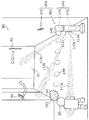
- FIG. 1 is a diagram showing an outline of a purification system according to the first embodiment.
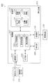
- FIG. 2 is a block diagram illustrating a configuration of the purification system according to the first embodiment.
- FIG. 3 is a diagram illustrating an example of walking information stored in the storage unit of the purification device according to the first embodiment.
- FIG. 4 is a flowchart showing the operation of the purification device according to the first embodiment when the purification command is not acquired.
- FIG. 5 is a diagram illustrating an example of position information and movement information stored in the storage unit of the purification apparatus according to the first embodiment.
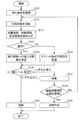
- FIG. 6 is a flowchart showing the operation of the purification device according to the first embodiment and the operation when a purification command is acquired.
- FIG. 1 is a diagram showing an outline of a purification system according to the first embodiment.
- FIG. 2 is a block diagram illustrating a configuration of the purification system according to the first embodiment.
- FIG. 3 is a diagram illustrating an example of walking information stored in the storage
- FIG. 7 is a diagram illustrating the outside of a space to which the purification system according to Embodiment 2 is applied.
- FIG. 8 is a block diagram illustrating a configuration of the purification system according to the second embodiment.
- FIG. 9 is a diagram illustrating an example of walking information stored in the storage unit of the purification device according to the second embodiment.
- FIG. 10 is a flowchart illustrating the operation of the purification system according to the second embodiment when the purification command is acquired.
- FIG. 11 is a diagram illustrating an outline of the purification system according to the third embodiment.
- FIG. 12 is a block diagram illustrating a configuration of the purification system according to the third embodiment.
- FIG. 13 is a block diagram illustrating a configuration of the purification system according to the first modification of the third embodiment.
- FIG. 14 is a block diagram illustrating a configuration of the purification system according to the second modification of the third embodiment.
- FIG. 15 is a block diagram illustrating a configuration of a fluorescence detection sensor included in the purification system according to the second modification of the third embodiment.
- FIG. 16 is a diagram illustrating an outline of the purification system according to the fourth embodiment.
- FIG. 17 is a block diagram illustrating a configuration of the purification system according to the fourth embodiment.
- a target position for reaching the injection material injected from the injection device is determined, and the injection material is based on the position information of the object obtained by the first sensor.
- the jetting device is in a range including the target position. Controlling the injection of the spray.
- the injection of the injection is controlled based on the result of the determination as to whether or not the object is in contact with the injection. For this reason, for example, it is possible to inject the ejected material so as not to contact the object and sufficiently reach the target position, so that the target position can be efficiently purified using the ejected material.
- the injection device may cause the injection device to inject the injection material into the range in the control.
- control unit may cause the spray device to inject the spray into the range in the control.
- the target position can be efficiently purified using the injection.
- the injection device injects the injection object in the range so that the injection object does not contact the object in the control. May be restricted.
- the injection device injects the injected object in the range so that the injected object does not contact the object in the control. May be restricted.
- the propellant may contain a medicine.
- the target position may be determined using a second sensor.
- the second sensor detects a position where the possibility of occurrence of bacteria or virus is high
- the position can be purified as the target position.
- purification in the space can be performed efficiently.
- it can suppress that a spray is injected toward the position where microbe or virus does not generate
- the second sensor may be at least one selected from the group consisting of a sound detection sensor, an infrared sensor, an image sensor, and a fluorescence detection sensor.
- the second sensor is at least one of a sound detection sensor, an infrared sensor, and an image sensor, for example, a sound or an action based on cough or sneezing by a sick person can be detected.
- the second sensor is a fluorescence detection sensor, it is possible to detect the fluorescence emitted from the amino acid constituting the bacterium or virus.
- the target position may be a position where aerosol exists in a space where the injection device is arranged.
- Aerosols include, for example, sprays scattered by coughing or sneezing by a sick person, pollen, or the like.
- a predetermined position may be determined as the target position.
- the target position can be efficiently purified by predetermining the target position as a target position where the possibility of the presence of bacteria or viruses is high.
- the target position determination process can be simplified. For this reason, simplification of the structure of a purification apparatus and reduction of a processing amount are realizable.
- the target position may be at least a part of a door arranged in a space where the injection device is arranged.
- the first sensor is disposed in a second space separated from the first space in which the injection device is disposed via a door, and the purification method is further based on the position information of the object. Determining whether or not the object approaches the door during the period, and restricting the injection device from injecting the injection when it is determined that the object approaches the door. .
- the first sensor is disposed in a second space separated from the first space in which the injection device is disposed via a door, and the purification method is further based on the position information of the object. And determining whether or not the object approaches the door during the period, and after determining that the object approaches the door, the injection device may restrict the injection of the injected material. .
- the door when the object is a person, the door may be opened and closed when the person approaches the door. At this time, an airflow or the like is generated by opening and closing the door, and the traveling direction of the ejected matter is changed by the generated airflow, and the ejected matter may not reach the target position.
- the purification method according to this aspect since the injection of the ejected material is limited when it is determined that the object approaches the door, the injected material does not reach the target position, and the injected material is wasted. Can be suppressed.
- the injection may be waited for a first period, or the injection may be stopped.
- the injection can be injected at a timing when the object does not contact the injection. Therefore, a sufficient amount of the ejected matter can reach the target position, and the target position can be purified efficiently.
- the stopped state is equal to or longer than a second period. It may be determined whether or not it is continued, and when it is determined that the stopped state continues for the second period or longer, a signal may be output to the external device.
- the stopped state is equal to or longer than a second period.
- a signal may be output to the external device after determining whether or not it is continued and determining that the stopped state continues for the second period or longer.
- the purification method according to this aspect can be used not only for purification of the target position but also for detection of an abnormality in the target space.
- the propellant may be an air current or a mist. At this time, the propellant may not contain a medicine.
- bacteria or viruses can be moved or diffused by jetting an airflow to a target position. For this reason, the quantity of the microbe or virus which exists in the target position can be reduced, and purification of the target position can be performed efficiently.
- the propellant may be an air stream, and the air stream may include a vortex ring formed of a gas containing a drug.
- the medicine can be efficiently put on the vortex ring and reach the target position. Therefore, a sufficient amount of medicine can be conveyed to the target position, and the target position can be purified efficiently.
- a purification device includes an injection unit that injects an injection product, and a control unit that controls the injection unit, and the control unit is a target position at which the injection product is reached. Based on the position information of the object obtained by the first sensor, the object comes into contact with the ejected object during a period from when the ejected object is ejected from the ejecting unit to the target position. It may be determined whether or not to perform, and based on the result of the determination, it may be controlled that the injection unit injects the injection into a range including the target position.
- a purification system may include the purification device according to the above aspect and the first sensor.
- a purification device includes a storage unit for storing position information of an object detected by one or more sensors, and a purification unit that locally discharges a medicine toward a target position.
- a control unit and when the purification command is acquired, the control unit reads the position information from the storage unit and, based on the read position information, discharges the medicine to the target position. It is determined whether or not the object interferes with the traveling path of the medicine in a period until it reaches, and when it is determined that the object interferes with the traveling path, the discharge of the medicine by the purifying unit is restricted. .
- the medicine can be used efficiently.
- the medicine can be ejected at a timing at which the object does not interfere with the traveling path, a sufficient amount of medicine can be transported to the target position, and the target position can be efficiently purified.
- one of the one or more sensors is a sensor disposed in the same space as the purification device, and the control unit determines that the object enters the traveling path during the period as the determination. If it is determined that the object enters the travel route, the discharge of the medicine by the purification unit may be restricted.
- the discharge of the medicine is restricted, so that it is possible to prevent the medicine from being transported to the target position due to the object blocking the traveling path.
- the object is an animal such as a person or a pet, it is possible to suppress the drug from hitting the object, so that the purification power is strong regardless of the influence on the health of the object.
- Drugs can be used. By using a chemical having a strong purification power, the target position can be efficiently purified.
- one of the one or more sensors is a sensor disposed in a space separated from a space in which the purification device is disposed with a door therebetween, and the control unit is A second determination of whether an object approaches the door during the period may be performed, and when it is determined that the object approaches the door, the discharge of the medicine by the purification unit may be limited.
- the door when the object is a person, the door may be opened and closed when the person approaches the door. At this time, an airflow or the like is generated by opening and closing the door, and the generated airflow may cause the drug to deviate from the traveling path and be not transported to the target position.
- the purification device since the discharge of the medicine is limited when it is determined that the object approaches the door, it is possible to prevent the medicine from being transported to the target position. .
- the target position may be at least a part of the door.
- control unit may wait for a predetermined period of time or stop the discharge of the medicine by the purification unit.
- the medicine can be fired at a timing at which the object does not interfere with the traveling path. Therefore, a sufficient amount of medicine can be conveyed to the target position, and the target position can be purified efficiently.
- the purification device further includes a communication unit that communicates with an external device, and the control unit further determines whether the state of the object is a stopped state or a moving state And a predetermined signal may be output to the external device via the communication unit when the stopped state continues for a predetermined period or longer.
- the purification apparatus which concerns on this aspect, it can utilize not only for purification
- the purifying unit may launch a vortex ring formed of a gas containing the drug toward the target position.
- the medicine can be efficiently transported to the target position on the vortex ring. Therefore, a sufficient amount of medicine can be conveyed to the target position, and the target position can be purified efficiently.
- a purification system includes the purification device and the one or more sensors.
- the purification method is a purification method in which a medicine is locally ejected toward a target position, the position information of an object detected by one or more sensors is stored in a storage unit, and the purification is performed.
- the position information is read from the storage unit, and the object is in a period from when the medicine is fired until the target position is reached based on the read position information. It is determined whether or not to interfere with the path, and when it is determined that the object interferes with the traveling path, the discharge of the medicine by the purification unit is limited.
- all or part of a circuit, unit, device, member, or part, or all or part of a functional block in a block diagram is a semiconductor device, a semiconductor integrated circuit (IC), or an LSI (Large Scale Integration). It may be performed by one or more electronic circuits that contain it.
- the LSI or IC may be integrated on a single chip, or may be configured by combining a plurality of chips.
- the functional blocks other than the memory element may be integrated on one chip.
- it is called LSI or IC, but the name changes depending on the degree of integration and may be called system LSI, VLSI (Very Large Scale Integration), or ULSI (Ultra Large Scale Integration).
- a Field Programmable Gate Array (FPGA), which is programmed after the manufacture of the LSI, or a reconfigurable logic device that can reconfigure the connection relationship inside the LSI or set up the circuit partition inside the LSI can be used for the same purpose.
- FPGA Field Programmable Gate Array
- all or part of the functions or operations of the circuit, unit, device, member, or part can be executed by software processing.
- the software is recorded on a non-transitory recording medium such as one or more ROMs, optical disks, hard disk drives, etc., and when the software is executed by a processor, the functions specified by the software are It is executed by a processor and peripheral devices.
- the system or apparatus may comprise one or more non-transitory recording media in which software is recorded, a processor, and required hardware devices, such as an interface.
- FIG. 1 is a diagram showing an outline of a purification system 100 according to the present embodiment.
- the purification system 100 is a system that purifies a predetermined place in a predetermined space such as a room with a chemical launched by the purification device 102.
- FIG. 1 shows a space 90 including a place to be purified by the purification device 102.
- the space 90 is a room of a building such as a nursing facility or a hospital.
- the space 90 is, for example, a space partitioned by walls, windows, doors, floors, ceilings, and the like, and is a closed space, but is not limited thereto.
- the space 90 may be an outdoor open space.
- the space 90 may be an internal space of a moving body such as a bus or an airplane.
- a door 91 and a door 92 are provided in the space 90. Both the door 91 and the door 92 can be freely opened and closed from the inside and outside of the space 90.
- the door 91 is a sliding door, and a handle 93 is provided.
- the handle 93 is, for example, an elongated rod-shaped member that is easy for the person 80 to grip, and is fixed to the surface of the door plate of the door 91.
- the handle 93 may be a recess that is recessed to the extent that the fingertip of the person 80 enters the door plate of the door 91.
- the person 80 can open and close the door 91 by placing the hand on the handle 93 and pulling the door 91 sideways.
- a white straight arrow illustrated near the handle 93 indicates a direction in which the door 91 is opened.
- the shape and attachment position of the handle 93 are not particularly limited.
- the door 92 is a hinged door and is provided with a door knob 94. At least a part of the door knob 94 is rotatably provided.
- the person 80 can open and close the door 92 by turning the door knob 94 and pulling it forward or pushing it backward.
- a white curved arrow illustrated near the door knob 94 indicates a direction in which the door 92 is opened.
- the shape and attachment position of the door knob 94 are not particularly limited.
- the handle 93 and the door knob 94 are target positions to be purified. That is, the handle 93 and the door knob 94 are positions where the ejected matter should reach. Specifically, the handle 93 and the door knob 94 are positions where the medicine to be discharged by the purification device 102 should reach.
- the handle 93 and the door knob 94 are parts that many people usually touch when opening and closing the door. For this reason, when pathogens, such as a virus or bacteria, have adhered to the handle 93 and the doorknob 94, it leads to the expansion of disease infection. For this reason, in the purification system 100 according to the present embodiment, the handle 93 and the door knob 94 are set as target positions to be purified.
- the target position is not limited to a part of the door such as the handle 93 and the door knob 94.
- it may be an operation terminal of a household electrical appliance existing in the space 90, or may be a wiping trace of a vomit of a person 80.
- the purification device 102 is disposed in the space 90. Note that the entire purification device 102 may not be disposed in the space 90. For example, only the medicine ejection port 146 may be located in the space 90. For example, the purification device 102 is fixed at a predetermined position in the space 90.
- the purification device 102 is an example of an injection device that injects an injection.
- the propellant is, for example, an air current and contains a medicine.
- the purification device 102 is a device that locally ejects a medicine toward a target position. By locally ejecting the drug, it is possible to suppress the drug from reaching a range where no purification is necessary, and to reduce the waste of the drug.
- locally firing means that the medicine is not sprayed so as to diverge over the entire space 90, but the medicine is fired only within a predetermined range around a predetermined firing direction.
- the range where the medicine reaches at the target position is a range where the diameter is several cm or more and 100 cm or less.
- the diameter in the range may be 5 cm or more and 100 cm or less.
- the traveling path of the medicine is a portion through which the medicine passes from the medicine ejection port 146 of the purification device 102 to the target position.
- the length of the traveling path is, for example, several centimeters to several tens of meters, but is not limited thereto.
- the purification device 102 launches a vortex ring 148 formed of a gas containing a drug toward a target position. That is, the medicine is transported to the target position so as to fly in the air. For this reason, the traveling path of the medicine is a flight path of the medicine formed in the air.
- the drug is a liquid for purifying and detoxifying microorganisms such as viruses or bacteria.
- the drug is hypochlorous acid water, sodium hypochlorite preparation, alcohol preparation or the like.
- medical agent may not be a liquid, but a gas or solid may be sufficient as it.
- a person 80 exists in the space 90, and the person 80 can freely walk around in the space 90.
- the person 80 is an example of a movable object, and is an object that may come into contact with a jet.
- the person 80 is an object that may interfere with the traveling path of the medicine.
- the object is not limited to a person but may be an animal such as a pet. Alternatively, the object may not be a living thing, and may be a cleaning robot or the like.
- the purification system 100 transports the medicine to the target position away from the purification device 102 even in the space where the person 80 exists, and purifies the target position with the transported medicine.
- FIG. 2 is a block diagram showing the configuration of the purification system 100 according to the present embodiment.
- the purification system 100 includes a purification device 102, one or more indoor sensors 112, and a management device 152.
- Each of the one or more indoor sensors 112 is an example of a first sensor, and is disposed in the same space as the purification device 102, for example.
- the one or more indoor sensors 112 are human sensors that detect the position of the person 80.
- FIG. 1 shows three indoor sensors 112a, 112b, and 112c as one or more indoor sensors 112.
- Each of the three indoor sensors 112a, 112b, and 112c has the same configuration.
- the three indoor sensors 112a, 112b, and 112c will be collectively referred to as the indoor sensor 112 unless otherwise distinguished.
- the number of indoor sensors 112 provided in the purification system 100 may be one or two, or may be four or more.
- the indoor sensor 112 is, for example, an infrared sensor having a predetermined detection area.
- the indoor sensor 112 outputs a detection signal when the person 80 enters the detection area.
- the detection signal is acquired by the control unit 120 of the purification device 102 via the communication unit 110 of the purification device 102.
- FIG. 1 shows the detection areas 113a, 113b, and 113c of the three indoor sensors 112a, 112b, and 112c with dot shading.
- the detection areas 113a, 113b, and 113c are different from each other. Note that the detection areas 113a, 113b, and 113c may partially overlap.
- the detection region 113a is formed at a position farthest from the traveling path of the medicine, specifically, the flight path of the vortex ring 148 in the space 90 among the plurality of detection regions.
- the detection region 113c is formed at a position closest to the flight path of the vortex ring 148 among the plurality of detection regions.
- the detection area 113b is formed between the detection area 113a and the detection area 113c.
- a unique identifier is assigned to each indoor sensor 112.
- the detection signal includes an identifier unique to the indoor sensor that outputs the detection signal.
- a detection signal is output from the indoor sensor 112a.
- a detection signal is output from the indoor sensor 112b.
- a detection signal is output from the indoor sensor 112c.
- the purifying apparatus 102 that has received the detection signals in order knows the order of the received detection signals in the order of the indoor sensor 112a, the indoor sensor 112b, and the indoor sensor 112c. Thereby, in the purification apparatus 102, the moving direction of the person 80 is computable. Further, the moving speed of the person 80 can be calculated based on the reception time of the detection signal.
- Each of the indoor sensors 112a, 112b, and 112c acquires the distance from the sensor to the person 80 in each detection area, and outputs the distance information indicating the acquired distance in the detection signal. Thereby, the purification apparatus 102 can calculate the moving direction and moving speed of the person 80 in more detail. Therefore, it can be determined with higher accuracy whether or not the person 80 interferes with the traveling path of the medicine.
- Each of the indoor sensors 112a, 112b, and 112c may not be able to acquire the distance to the person 80, and may determine only the presence or absence of the person 80 in the detection area.
- the indoor sensor 112 may not be an infrared sensor.
- the indoor sensor 112 may be an image sensor that generates a still image or a moving image by photographing the space 90. By analyzing the image obtained by the image sensor, the position of the person 80 can be specified.
- the indoor sensor 112 may be a distance measuring sensor such as a TOF (Time Of Flight) type sensor.
- the indoor sensor 112 may be a LIDAR (Laser Imaging Detection and Ranging) type sensor.
- the three indoor sensors 112a, 112b, and 112c are integrated with the purification device 102 as shown in FIG. Alternatively, at least one of the three indoor sensors 112a, 112b, and 112c may be provided separately from the purification device 102. For example, at least one of the three indoor sensors 112a, 112b, and 112c may be provided on a wall or ceiling constituting the space 90.
- the three indoor sensors 112a, 112b, and 112c output a detection signal to the purification device 102 by communicating with the communication unit 110 of the purification device 102.
- the purification device 102 includes a communication unit 110, a control unit 120, a storage unit 130, a purification unit 140, a communication unit 150, and an input unit 160.
- the communication unit 110 communicates with each of the plurality of indoor sensors 112 by wire or wireless.
- the communication unit 110 performs wireless communication conforming to a wireless communication standard such as Wi-Fi (registered trademark), Bluetooth (registered trademark), or ZigBee (registered trademark).
- the communication unit 110 acquires a detection signal from each of the plurality of indoor sensors 112.
- the acquired detection signal is output to the sensor control unit 122 of the control unit 120.
- the control unit 120 includes a sensor control unit 122, a command generation unit 124, and a purification control unit 126.
- the control unit 120 is realized by, for example, a nonvolatile memory in which a program is stored, a volatile memory that is a temporary storage area for executing the program, an input / output port, and a processor that executes the program.
- Each of the sensor control unit 122, the command generation unit 124, and the purification control unit 126 included in the control unit 120 may be realized by software executed by a processor, or realized by hardware such as an electronic circuit including a plurality of circuit elements. May be.
- the sensor control unit 122 controls operations related to the indoor sensor 112. Specifically, the sensor control unit 122 generates the position information 134 of the person 80 based on the detection signal output from the indoor sensor 112 and stores it in the storage unit 130.
- the sensor control unit 122 when the sensor control unit 122 receives a detection signal from the indoor sensor 112 via the communication unit 110, the sensor control unit 122 compares the identifier included in the detection signal with the sensor information 132 stored in the storage unit 130. Thus, the indoor sensor 112 that is the transmission source of the detection signal is specified. The sensor control unit 122 generates the position information 134 of the person 80 for each identified indoor sensor 112 based on the distance information included in the detection signal.
- the sensor control unit 122 stores the position information 134 in the storage unit 130 in association with the detection time.
- the detection time is, for example, the time when the communication unit 110 acquires the detection signal.
- the detection time may be the time indicated by the time information included in the detection signal.
- the sensor control unit 122 further determines the state of the person 80 based on the detection signal. Specifically, the sensor control unit 122 determines whether the state of the person 80 is a moving state where the person 80 is moving or a stopped state where the person 80 is not moving. judge. For example, the sensor control unit 122 determines the state of the person 80 by determining whether or not there is a change in the position of the person 80 indicated by the two pieces of position information 134 associated with two consecutive times. When the position of the person 80 changes, the sensor control unit 122 determines that the state of the person 80 is a moving state. When the position of the person 80 has not changed, the sensor control unit 122 determines that the state of the person 80 is a stopped state. The sensor control unit 122 stores movement information 136 indicating the determination result in the storage unit 130.
- the sensor control unit 122 outputs a predetermined signal to the management device 152 via the communication unit 150 when the stopped state continues for a predetermined period or longer.
- the sensor control unit 122 outputs a signal to the management device 152 via the communication unit 150 to notify the management device 152 of the possibility of abnormality in the space 90 in which the purification device 102 is installed. Can do.
- the signal output from the sensor control unit 122 is, for example, a signal for performing an alarm sound or an alarm display, but is not limited thereto. Further, the output destination of the signal is not limited to the management device 152, and may be a speaker disposed outside the space 90 or a light emitting device such as a red light.
- the command generation unit 124 generates a purification command and outputs the generated purification command to the purification control unit 126.
- the purification command is a command for instructing purification of the target position.
- the purification command includes information indicating the target position.
- the purification command may include a control parameter relating to the strength of purification.
- the control parameters are, for example, the concentration of the drug, the number of times the vortex ring 148 is fired, and the air volume of the vortex ring 148.
- the command generation unit 124 generates a purification command based on, for example, predetermined schedule information.
- the schedule information is information indicating the timing at which the target position is purified, that is, the timing at which the injection is performed.
- the schedule information is information indicating the timing at which the medicine is ejected.
- the schedule information indicates a time interval at which the medicine is ejected such as 30 minutes or 1 hour, or a time at which the medicine is ejected such as 10:00 and 10:30.
- the command generation unit 124 may generate a purification command based on a user operation received by the input unit 160. Thereby, the target position can be purified at an arbitrary timing desired by the user.
- the command generation unit 124 may generate a purification command based on an instruction acquired via the management device 152 and the communication unit 150. Thereby, for example, the target position can be purified at any timing desired by the administrator or user of the management device 152.
- the purification control unit 126 controls the purification unit 140. Specifically, the purification control unit 126 determines a target position to reach the injection. Based on the position information of the person 80 obtained by the indoor sensor 112, the purification control unit 126 makes contact with the ejected matter during the period from when the ejected matter is ejected from the purifying unit 140 until it reaches the target position. It is determined whether or not to do. Based on the result of the determination, the purification control unit 126 controls the purification unit 140 to inject the injection material into a range including the target position. More specifically, the purification control unit 126 reads the position information 134 from the storage unit 130 when a purification command is acquired.
- the purification control unit 126 determines whether the person 80 interferes with the traveling path of the medicine during a period from when the medicine is fired until it reaches the target position (hereinafter referred to as a required period). It is determined whether or not there is a possibility of interference.
- the required period is a period from when the vortex ring 148 is fired from the purification device 102 until the fired vortex ring 148 reaches the target position.
- the required period is a period from when the first vortex ring 148 is fired from the purification device 102 until the last vortex ring 148 reaches the target position.
- the purification control unit 126 calculates the required period based on the distance between the target position and the purification device 102, the firing speed of the vortex ring 148, the firing period, the number of firings, and the like.
- the traveling path of the drug corresponds to the flight path of the vortex ring 148.
- the traveling path of the medicine is a cylindrical range having a straight line connecting the launch port 146 of the vortex ring 148 of the purification device 102 and the target position as an axis.
- the diameter in the range corresponds to the outer diameter of the vortex ring 148.
- the advancing path may be curved according to the movement of the vortex ring 148.
- the interference is that the person 80 enters the traveling path.
- the purification control unit 126 determines whether or not the person 80 enters the path of travel of the medicine in a required period, that is, determines the possibility of entering, as the possibility of interference.
- the purification control unit 126 reads the position information 134, the movement information 136, and the walking information 138 from the storage unit 130, and determines the possibility of entering based on the read position information 134, the movement information 136, and the walking information 138. .
- the purification unit 140 restricts the purification unit 140 from injecting the injection so that the person 80 does not contact the injection. For example, when it is determined that the person 80 interferes with the traveling path of the medicine, the purification control section 126 restricts the discharge of the medicine by the purification section 140. In the present embodiment, the purification control unit 126 restricts the discharge of the drug by the purification unit 140 when it is determined that the person 80 enters the path of travel of the drug.
- the launch restriction is, for example, standby or cancellation of launch.
- the purification control section 126 waits for or cancels the discharge of the medicine by the purification section 140 for a predetermined period.
- the period of waiting for launch (hereinafter referred to as the standby period) is, for example, several seconds or more and several minutes or less.
- the purification control part 126 determines again whether the person 80 interferes with the advancing path
- the purification control unit 126 for example, emits the medicine when the medicine cannot be ejected when the determination of the possibility of interference is repeated a predetermined number of times or when a predetermined period has elapsed after receiving the purification command. Discontinue. When the firing is stopped, the purification control unit 126 enters a standby state until the next purification command is acquired. If it is determined that the person 80 interferes with the travel path, the purification control unit 126 may immediately stop the firing without waiting for the person 80.
- the purification control unit 126 causes the purification unit 140 to inject the injection material when it is determined that the person 80 does not contact the injection material. For example, when it is determined that the person 80 does not interfere with the traveling path of the medicine, the purification control section 126 causes the purification section 140 to fire the vortex ring 148 so as to fire the medicine. For example, the purification control unit 126 sets conditions such as the concentration of the drug, the number of times the vortex ring 148 is fired, and the air volume of the vortex ring 148 based on the control parameters included in the purification command. The purification unit 140 launches the vortex ring 148 containing the medicine based on the set condition.
- the storage unit 130 is, for example, a non-volatile storage device such as a semiconductor memory or an HDD (Hard Disk Drive). As shown in FIG. 2, sensor information 132, position information 134, movement information 136, and walking information 138 are stored in the storage unit 130.
- HDD Hard Disk Drive
- the sensor information 132 indicates the identifier of each of the plurality of indoor sensors 112 connected to the purification device 102 by wire or wirelessly and the position of the detection area in association with each other.
- the sensor information 132 is updated when the indoor sensor 112 is newly added and when the detection area of the existing indoor sensor 112 is changed.
- the position information 134 is information indicating the position of the person 80 detected by the indoor sensor 112.
- the position information 134 is associated with the detection time for each sensor.
- the movement information 136 is information indicating the state of the person 80 detected by the indoor sensor 112. Specifically, the movement information 136 indicates whether the state of the person 80 is a moving state or a stopped state.
- the walking information 138 indicates the walking speed of the person 80 in the room, as shown in FIG.
- FIG. 3 is a figure which shows an example of the walk information 138 memorize
- the walking speed indicated by the walking information 138 is, for example, an average value of walking speeds by age.
- the walking information 138 indicates, for example, an average value of walking speeds of elderly people in their 70s to 80s as walking speeds of the person 80.
- the walking information 138 can be used as it is without being updated.
- the walking information 138 may indicate a walking speed unique to the person 80, that is, an individual walking speed. For example, when the person 80 in the space 90 such as a care facility is always the same person, the person 80 detected by the indoor sensor 112 is almost the same person. Therefore, the walking information 138 indicates the walking speed of the individual, so that it can be accurately determined whether or not the person 80 enters the traveling route of the medicine.
- the purification unit 140 is an example of an injection unit that injects an injection.
- the purification unit 140 locally ejects the medicine toward the target position.
- the purification unit 140 launches a medicine when a purification command is acquired by the control unit 120.
- the purifying unit 140 launches a vortex ring 148 formed of a gas containing a drug toward a target position.
- the purification unit 140 includes a liquid storage tank 142, a cavity 144, and a launch port 146.
- the liquid storage tank 142 is a container for storing a medicine.
- the hollow portion 144 is a space in which a gas for forming the vortex ring 148 is stored.
- the launch port 146 is an opening that connects the cavity 144 and the outside, and is an opening through which the vortex ring 148 is launched.
- the hollow portion 144 is provided with a structure (not shown) that instantaneously changes the internal capacity in order to push out the internal gas, for example.
- a structure (not shown) that instantaneously changes the internal capacity in order to push out the internal gas, for example.
- a film-like member having elasticity and a striking device that blows and deforms the film-like member. Gas is pushed out from the outlet 146 by momentarily deforming the membranous member by the striking device. When the gas pushed out from the cavity 144 passes through the launch port 146, a vortex ring 148 is formed and ejected in a predetermined direction.
- the direction of the launch port 146 can be changed in the vertical direction and the horizontal direction, for example. Thereby, the purifier 140 can launch the vortex ring 148 toward a plurality of target positions.
- the communication unit 150 communicates with an external device. Specifically, the communication unit 150 communicates with the management device 152 in a wired or wireless manner. For example, the communication unit 150 performs wireless communication conforming to a wireless communication standard such as Wi-Fi (registered trademark), Bluetooth (registered trademark), or ZigBee (registered trademark). Note that the communication unit 110 and the communication unit 150 may be realized by the same communication interface.
- a wireless communication standard such as Wi-Fi (registered trademark), Bluetooth (registered trademark), or ZigBee (registered trademark).
- Wi-Fi registered trademark
- Bluetooth registered trademark
- ZigBee registered trademark
- the management device 152 is an example of an external device connected via the communication unit 150.
- the management device 152 is arranged in a management room where a caregiver who cares for a resident of a care facility stays, a so-called nurse center of a hospital, or the like.
- the management device 152 When the management device 152 receives a predetermined signal from the purification device 102 via the communication unit 150, the management device 152 performs a notification process for notifying the possibility that an abnormality has occurred in the space 90.
- the management device 152 is connected to a display device or a speaker (not shown), and notifies an administrator or the like of the possibility of an abnormality by outputting an image or sound.
- the input unit 160 receives an operation input to the purification device 102 from the outside.
- the input unit 160 is realized by, for example, a touch panel display or a physical button switch. Or the input part 160 may be implement
- FIG. For example, a button switch for performing purification may be provided as an input unit 160 on the outer casing of the purification device 102. When the button switch is pressed, the command generation unit 124 may generate a purification command.
- the input unit 160 may accept input of conditions such as the concentration of the drug, the number of times the vortex ring 148 is fired, and the air volume of the vortex ring 148.
- the input unit 160 may accept input of schedule information.
- FIG. 4 is a flowchart showing the operation of the purification device 102 according to the present embodiment when the purification command is not received.
- the operation shown in FIG. 4 is mainly executed by the sensor control unit 122.
- the sensor control unit 122 waits until the person 80 is detected (No in S10). Specifically, the sensor control unit 122 stands by until a detection signal is received from at least one of the plurality of indoor sensors 112 via the communication unit 110.
- the sensor control unit 122 When the person 80 is detected (Yes in S10), that is, when the detection signal is received via the communication unit 110, the sensor control unit 122 generates the position information 134 of the person 80 based on the received detection signal. And stored in the storage unit 130 (S12).
- the sensor control unit 122 determines the state of the detected person 80 based on the position information 134 (S14). Specifically, the sensor control unit 122 determines whether the detected state of the person 80 is a moving state or a stopped state. When the state of the person 80 is the moving state (Yes in S14), the sensor control unit 122 stores the movement information 136 indicating the moving state in the storage unit 130 (S16).
- the sensor control unit 122 determines whether or not the continuous stop period is equal to or longer than the set period (S18).
- the continuous stop period is a period in which the person 80 continues to be in a stop state without being determined as a moving state after it is determined as the stop state.
- the set period is a predetermined period such as 1 hour, for example.
- the sensor control unit 122 When the continuous stop period is equal to or longer than the set period (Yes in S18), the sensor control unit 122 outputs a predetermined signal to the management device 152 via the communication unit 150 (S20). After the signal is output and when the continuous stop period is not longer than the set period (No in S18), the sensor control unit 122 stores movement information 136 indicating that the state of the person 80 is in the stop state in the storage unit 130. Store (S16).
- the detection signal is repeatedly output in units of, for example, several seconds or 1 second or less. For this reason, the process shown in FIG. 4 is repeatedly executed by the sensor control unit 122.
- FIG. 5 is a diagram illustrating an example of the position information 134 and the movement information 136 stored in the storage unit 130 of the purification device 102 according to the present embodiment.
- FIG. 5 shows the detection results of the two sensors A and B in association with the detection time.
- Sensor A and sensor B correspond to, for example, indoor sensors 112a and 112b, respectively.
- State A and state B indicate the state of the object first detected by the sensor A and the state of the object first detected by the sensor B, respectively.
- the position information 134 indicates that an object is detected at the position of the distance a at the time T ⁇ b> 1 in the detection area of the sensor A. Further, the position information 134 indicates that an object is detected at the position of the distance a at time T2 in the detection area of the sensor A. That is, in the sensor A, the position of the detected object does not change between time T1 and time T2. For this reason, the sensor control unit 122 determines that the state of the object is a stopped state. The sensor control unit 122 generates movement information 136 indicating that the vehicle is stopped at time T ⁇ b> 2 and stores the movement information 136 in the storage unit 130.
- an object is detected by both sensor A and sensor B. Specifically, objects are detected at two locations, a position of distance b in the detection area of sensor A and a position of distance c in the detection area of sensor B, respectively. For example, when two people exist in the space 90, a situation such as time T3 may occur.
- the sensor control unit 122 determines that the state of the object is the moving state because the distance detected by the sensor A is different between the time T2 and the time T3.
- a situation from time T2 to time T3 for example, a person who was at a position of distance a in the detection area of sensor A at time T2 moved to a position of distance b, and a new person A first situation can be assumed in which a new appearance appears at the position of the distance c in the B detection region.
- the person who was at the position of distance a in the detection area of sensor A at time T2 moves to the position of distance c in the detection area of sensor B, and the new person is the distance in the detection area of sensor A.
- a second situation can be assumed in which a new appearance appears at position b. It can be estimated based on the walking speed indicated by the walking information 138, for example. However, in any situation, there is no change in the presence of a person in the detection area, and no change in the movement of the person in the detection area of sensor A at time T2 has occurred. You don't have to.
- both the sensor A and the sensor B change the distance in the detection area. For this reason, the sensor control unit 122 determines that the states of the two objects detected by the sensors A and B are both in the moving state.
- the sensor control unit 122 determines that the state of the object detected by the sensor A is a moving state and the state of the object detected by the sensor B is a stopped state.
- the sensor control unit 122 can determine the state of the object based on the detection result of the indoor sensor 112. Further, the sensor control unit 122 can determine the approximate moving direction of the object from a plurality of time positions.
- FIG. 6 is a flowchart showing the operation of the purification apparatus 102 according to the present embodiment and the operation when a purification command is acquired. The operation shown in FIG. 6 is mainly executed by the purification control unit 126.
- the purification control unit 126 obtains a purification command (S30).
- the purification command is generated by the command generation unit 124 at a timing based on the schedule information or at a timing when an external input is received.
- the purification control unit 126 determines a target position to reach the injection (S32). Specifically, the purification control unit 126 determines a predetermined position as the target position.
- the storage unit 130 may store target position information indicating predetermined positions such as the handle 93 and the door knob 94.
- the purification control unit 126 reads the target position information from the storage unit 130 to determine a predetermined position as the target position. When a plurality of positions are determined in advance, the purification control unit 126 selects one position from the plurality of positions and determines the selected position as the target position. In addition, the purification control unit 126 may determine the position received via the input unit 160 as the target position.
- the purification command may include information indicating the target position.
- the purification control unit 126 may determine the target position based on the purification command.
- the determination of the target position (S32) may be performed before the purification command is acquired (before S30). Alternatively, the determination of the target position (S32) may be performed after reading the position information 134 or the like (after S34).
- the purification control unit 126 reads the position information 134, the movement information 136, and the walking information 138 from the storage unit 130 (S34). For example, the purification control unit 126 reads the position information 134 and the movement information 136 associated with a plurality of times closest to the time when the purification command is acquired.
- the purification control unit 126 determines the possibility of the person 80 entering the traveling route of the medicine (S36). Specifically, the purification control unit 126 determines the flight path of the vortex ring 148 as the traveling path of the medicine based on the positional relationship between the target position indicated by the purification command and the launch port 146. Further, the purification control unit 126 determines the position of the person 80 and the movement direction of the person 80 from the position information 134 and the movement information 136 when the purification command is acquired. Based on the determined position and moving direction and the walking speed indicated by the walking information 138, it is determined whether or not the detected person 80 enters the traveling route in the required period required for the medicine to reach the target position. .
- the purification control unit 126 causes the purification unit 140 to fire the vortex ring 148, thereby firing the drug toward the target position (S40).
- the purification control unit 126 waits for launch for a predetermined period such as several seconds (S42).
- a predetermined period such as several seconds (S42).
- the process returns to step S32, and the purification control unit 126 determines the target position, reads information from the storage unit 130, and determines the possibility of entering.
- the continuous standby period is a period in which the vortex ring 148 is not fired and is in a standby state after the firing command is acquired.
- the set period here is a predetermined period such as several tens of seconds or more and 30 minutes or less such as 30 seconds.
- the purification apparatus 102 can discharge a chemical
- the purification control unit 126 stops the discharge of the medicine (S46). For example, when the person 80 is working on the travel route, the person 80 may not move immediately.
- the discharge of the medicine is stopped, the operation shown in FIG. 6 is executed when the next purification command is acquired, and the target position is purified.
- the purification system 100 and the purification device 102 when there is a high possibility that an object enters the traveling path of the drug, the discharge of the drug is limited. Thereby, it can suppress that a chemical
- the case where the person 80, which is an example of an object that interferes with the traveling path of the medicine, is present in the same space 90 as the purification device 102 and the target position has been described.
- the second embodiment a case will be described in which an object that interferes with the traveling path of the medicine exists outside the space 90.
- differences from the first embodiment will be mainly described, and description of common points will be omitted or simplified.
- FIG. 7 is a view showing the outside of the space 90 to which the purification system 200 (see FIG. 8) according to the present embodiment is applied.
- FIG. 7 shows an outer space 95 exiting the door 91 of the space 90 shown in FIG.
- the space 95 is a space separated from the space 90 in which the purification device 202 (see FIG. 8) is disposed with a door 91 therebetween.
- the space 90 is an example of a first space in which the purification device 202 is disposed.
- the space 95 is an example of a second space separated from the space 90 via the door 91.
- the space 90 is an indoor space
- the space 95 is an outdoor space.
- the space 95 is, for example, a corridor connected to the space 90, but may be a living room different from the space 90.
- the outside of the door 91 is shown, but the same applies to the door 92 shown in FIG.
- FIG. 7 shows a situation where a person 82 is walking toward the door 91.
- the handle 93 of the door 91 is the target position for purification
- the target position itself moves when the person 82 opens and closes the door 91.
- the object that interferes with the traveling path of the medicine does not necessarily exist in the same space as the target position and the purification device 202 (see FIG. 8).
- the purification system 200 even when a person 82 is present in the space 95 outside the space 90 in which the purification device 202 (see FIG. 8) is disposed, The target position is purified by the transported medicine.
- FIG. 8 is a block diagram showing a configuration of the purification system 200 according to the present embodiment.
- the purification system 200 includes a purification device 202, one or more indoor sensors 112, one or more outdoor sensors 214, and a management device 152.
- Each of the one or more outdoor sensors 214 is an example of a first sensor and is disposed in the space 95.
- the one or more outdoor sensors 214 are human sensors that detect the position of the person 82.
- FIG. 7 shows three outdoor sensors 214a, 214b, and 214c as one or more outdoor sensors 214.
- Each of the three outdoor sensors 214a, 214b, and 214c has the same configuration.
- the three outdoor sensors 214a, 214b, and 214c will be collectively referred to as the outdoor sensor 214 unless otherwise distinguished.
- the number of outdoor sensors 214 included in the purification system 200 may be one or two, or four or more.
- the outdoor sensor 214 is an infrared sensor having a predetermined detection area, for example.
- the outdoor sensor 214 outputs a detection signal when the person 82 enters the detection area.
- the detection signal is acquired by the control unit 220 of the purification device 202 via the communication unit 210 of the purification device 202.
- the detection areas 215a, 215b, and 215c of the three outdoor sensors 214a, 214b, and 214c are shown with dot shading.
- the detection areas 215a, 215b, and 215c are different from each other.
- the detection areas 215a, 215b, and 215c may partially overlap.
- the detection area 215a is formed at a position farthest from the door 91 among the plurality of detection areas.
- the detection area 215c is formed at a position closest to the door 91 among the plurality of detection areas.
- the detection area 215b is formed between the detection area 215a and the detection area 215c.
- a unique identifier is assigned to each outdoor sensor 214 in order to identify the plurality of outdoor sensors 214.
- the detection signal includes an identifier unique to the outdoor sensor that outputs the detection signal.
- the identifier of the outdoor sensor 214 is assigned so as not to match the identifier of the indoor sensor 112.
- the purification device 202 can identify the indoor sensor 112 and the outdoor sensor 214 that are the transmission source of the detection signal based on the identifier included in the detection signal.
- a detection signal is output from the outdoor sensor 214a.
- a detection signal is output from the outdoor sensor 214b.
- a detection signal is output from the outdoor sensor 214c.
- the purifying apparatus 202 that has received the detection signals in order finds that the order of the received detection signals is the order of the outdoor sensor 214a, the outdoor sensor 214b, and the outdoor sensor 214c. Thereby, in the purification apparatus 202, it can be seen that the person 82 is approaching the door 91. Further, the moving speed of the person 82 can be calculated based on the reception time of the detection signal.
- the outdoor sensor 214 may not be an infrared sensor, but may be an image sensor or a distance measuring sensor.
- the purification device 202 is different from the purification device 102 according to Embodiment 1 in that it includes a communication unit 210 and a control unit 220 instead of the communication unit 110 and the control unit 120. To do.
- the storage unit 130 stores sensor information 232 and walking information 238 instead of the sensor information 132 and walking information 138.
- the communication unit 210 communicates with each of the plurality of indoor sensors 112 and the plurality of outdoor sensors 214 in a wired or wireless manner.
- the communication unit 210 performs wireless communication conforming to a wireless communication standard such as Wi-Fi (registered trademark), Bluetooth (registered trademark), or ZigBee (registered trademark).
- the communication unit 210 acquires detection signals from each of the plurality of indoor sensors 112 and each of the plurality of outdoor sensors 214. The acquired detection signal is output to the sensor control unit 222 of the control unit 220.
- the control unit 220 includes a sensor control unit 222, a command generation unit 124, and a purification control unit 226.
- the control unit 220 is realized by, for example, a nonvolatile memory in which a program is stored, a volatile memory that is a temporary storage area for executing the program, an input / output port, and a processor that executes the program.
- Each of the sensor control unit 222, the command generation unit 124, and the purification control unit 226 included in the control unit 220 may be realized by software executed by a processor, or realized by hardware such as an electronic circuit including a plurality of circuit elements. May be.
- the sensor control unit 222 controls operations related to the indoor sensor 112 and the outdoor sensor 214. Specifically, the sensor control unit 222 generates the position information 134 of the person 80 or the person 82 based on the detection signal output from each of the indoor sensor 112 and the outdoor sensor 214 and stores the position information 134 in the storage unit 130. The specific operation of the sensor control unit 222 is the same as that in the first embodiment.
- the purification control unit 226 controls the purification unit 140. As in the first embodiment, the purification control unit 226 determines the possibility of entering the person 80 in the space 90 as the possibility of interference. Furthermore, the purification control unit 226 determines whether or not the person 82 outside the space 90 approaches the door 91 during the required period, that is, the determination of the accessibility possibility, as the determination of the possibility of interference. That is, in the present embodiment, the interference includes that the person 82 approaches the door 91.
- the purification control unit 226 determines the possibility of entering. If the position of the person indicated by the read position information 134 is the space 95, the purification control unit 226 determines the accessibility. If the position of the person indicated by the position information 134 is both in the spaces 90 and 95, such as when there are a plurality of persons, the purification control unit 226 determines both the approachability and the accessibility.
- the purification control unit 226 restricts the purification unit 140 from injecting an injection. Specifically, when it is determined that the person 82 approaches the door 91, the purification control unit 226 restricts the discharge of the medicine by the purification unit 140.
- the purification control unit 226 causes the purification unit 140 to inject an injection. Specifically, when it is determined that the person 82 does not approach the door 91, the purification control unit 226 causes the purification unit 140 to fire the vortex ring 148, thereby firing the medicine.
- the specific operations of the restriction on the discharge and the discharge of the medicine are the same as those in the first embodiment.
- the sensor information 232 indicates the identifiers of the plurality of indoor sensors 112 and the identifiers of the plurality of outdoor sensors 214 connected to the purification device 202 by wire or wirelessly and the positions of the detection areas in association with each other.
- the sensor information 232 is updated when the indoor sensor 112 or the outdoor sensor 214 is newly added and when the detection area of the existing indoor sensor 112 or the outdoor sensor 214 is changed.
- the walking information 238 indicates the walking speed of the person 80 indoors and the person 82 outdoor as shown in FIG.
- FIG. 9 is a figure which shows an example of the walk information 238 memorize
- the walking speed indicated by the walking information 238 is, for example, an average value of walking speeds by age. For example, when the space 90 is a room of a care facility, the person 82 is a young caregiver or the like. For this reason, the walking information 238 indicates, for example, an average value of walking speeds in the 20s to 40s as the walking speed of the person 82.
- the outdoor speed B is faster than the indoor speed A.
- FIG. 10 is a flowchart showing the operation of the purification device 202 according to the present embodiment and the operation when a purification command is acquired.
- the operation shown in FIG. 10 is mainly executed by the purification control unit 226.
- the process from the acquisition of the purification command (S30) to the reading of information from the storage unit 130 (S34) is the same as in the first embodiment.
- the purification control unit 226 determines whether the detected position of the object is the indoor space 90 or the outdoor space 95 based on the read position information 134 (S53). Specifically, the purification control unit 226 determines which of the indoor sensor 112 and the outdoor sensor 214 is the read position information 134.
- the purification control unit 226 determines the possibility of the object entering the path of travel of the medicine (S36).
- the specific processing for determining the possibility of entering is the same as in the first embodiment.
- the purification control unit 226 determines the accessibility to the door 91 (S54). Specifically, as in the determination of the possibility of entering, the purification control unit 226 determines the position of the person 82 and the movement direction of the person 82 at the time when the purification command is acquired from the position information 134 and the movement information 136. decide. Based on the determined position and moving direction, and the walking speed indicated by the walking information 238, it is determined whether or not the detected person 82 reaches the door 91 in the required period required for the medicine to reach the target position. To do.
- both steps S36 and S54 are performed. That is, when both the person 80 and the person 82 are detected, the purification control unit 226 determines both the approach possibility and the approach possibility.
- the control unit 226 causes the purification unit 140 to fire the vortex ring 148, thereby firing the medicine toward the target position (S40).
- the purification control unit 226 waits for launch for a predetermined period such as several seconds (S42). The subsequent processing is the same as in the first embodiment.
- the purification system and the purification device 202 when there is a high possibility that an object approaches the door 91, the discharge of the medicine is limited. Thereby, it can suppress that a chemical
- the handle 93 of the door 91 may not be the target position.
- the door knob 94 of the door 92 may be the target position. Even in this case, when the door 91 is opened and closed, the travel path of the vortex ring 148 may be bent due to a change in the airflow caused by the opening and closing. For this reason, by determining the accessibility to the door 91, the medicine can be ejected at a timing when the door 91 is not opened and closed.
- Embodiment 3 (Embodiment 3) Subsequently, Embodiment 3 will be described.
- Embodiments 1 and 2 have described examples in which the target position to be purified is a predetermined position. In contrast, in the third embodiment, a case where the target position is determined based on the detection result using the sensor will be described. In the following description, differences from Embodiment 1 or 2 will be mainly described, and description of common points will be omitted or simplified.
- FIG. 11 is a diagram showing an outline of the purification system 300 according to the present embodiment.
- FIG. 11 schematically shows an aerosol 393 floating in the space 90.
- the aerosol 393 includes, for example, splashes scattered from the mouth of the person 80 when the person 80 coughs or sneezes.
- the droplets contain viruses or fungi. That is, it is highly likely that the aerosol 393 contains viruses or fungi floating in the space 90.
- the target position to be purified by the purification system 300 is a position where the aerosol 393 is included. Since the aerosol 393 is floating in the space 90, its position is not fixed and can change. Therefore, the purification system 300 includes a second sensor for detecting the position of the aerosol 393.
- the aerosol 393 may be pollen or PM2.5.
- FIG. 12 is a block diagram showing a configuration of the purification system 300 according to the present embodiment.
- the purification system 300 includes a purification device 302 instead of the purification device 102 and a new sound detection sensor 316 as compared with the purification system 100 according to the first embodiment. Is different.
- the sound detection sensor 316 is an example of a second sensor for detecting a position where the aerosol 393 is present.
- the sound detection sensor 316 is, for example, a microphone that detects sound generated by the person 80.
- the sound detection sensor 316 is a microphone having directivity in a plurality of directions, and detects the position of the sound generation source.
- the sound detection sensor 316 detects a sound generated when the person 80 coughs or sneezes, and detects the position of the generation source.
- the sound detection sensor 316 outputs a detection signal including position information indicating the position of the sound generation source.
- the sound detection sensor 316 is provided on a wall or ceiling constituting the space 90 as shown in FIG. Note that the sound detection sensor 316 may be provided integrally with the purification device 302, similarly to the indoor sensor 112.
- the purification device 302 is different from the purification device 102 according to the first embodiment in that a communication unit 310 and a control unit 320 are provided instead of the communication unit 110 and the control unit 120. To do.
- the communication unit 310 communicates with each of the plurality of indoor sensors 112 and the sound detection sensor 316 in a wired or wireless manner.
- the communication unit 310 performs wireless communication complying with a wireless communication standard such as Wi-Fi (registered trademark), Bluetooth (registered trademark), or ZigBee (registered trademark).
- the communication unit 310 acquires a detection signal from each of the plurality of indoor sensors 112 and the sound detection sensor 316.
- the acquired detection signal is output to the sensor control unit 322 of the control unit 320.
- the control unit 320 includes a sensor control unit 322, a command generation unit 124, and a purification control unit 126.
- the control unit 320 is realized by, for example, a nonvolatile memory in which a program is stored, a volatile memory that is a temporary storage area for executing the program, an input / output port, and a processor that executes the program.
- Each of the sensor control unit 322, the command generation unit 124, and the purification control unit 126 included in the control unit 320 may be realized by software executed by a processor, or realized by hardware such as an electronic circuit including a plurality of circuit elements. May be.
- the sensor control unit 322 controls operations related to the indoor sensor 112 and the sound detection sensor 316.
- the operation related to the indoor sensor 112 is the same as that in the first embodiment.
- sensor control unit 322 further determines a target position based on a detection signal output from sound detection sensor 316. Specifically, the sensor control unit 322 acquires position information indicating the position of the sound source due to coughing or sneezing of the person 80 from the detection signal output from the sound detection sensor 316, and based on the acquired position information.
- the position of the aerosol 393 including the splashes scattered by coughing or sneezing is determined as the target position.
- the sensor control unit 322 determines a position included in a predetermined range centered on the position indicated by the position information as the target position.
- the predetermined range is a range determined based on the splashing distance of the splash. The splashes that scatter with sneeze usually scatter farther than the splashes that scatter with cough, so the predetermined range for sneezing may be greater than the predetermined range for coughing.
- the predetermined range is, for example, a range of tens of centimeters to several meters.
- the sensor control unit 322 may determine the position itself indicated by the position information as the target position.
- bacteria or viruses floating in the space 90 generated together with coughing or sneezing can be efficiently purified.
- the sound detection sensor 316 can detect a sound accompanying coughing or sneezing, and thus bacteria or viruses can be efficiently purified.
- the operation of the purification system 300 according to the present embodiment is the same as the operation of the purification system 100 according to the first embodiment.
- the operation shown in FIG. 6 may be started.
- the command generation unit 124 may generate a purification command when the sound detection sensor 316 detects coughing or sneezing of the person 80.
- a sensor of a different type from the sound detection sensor 316 can be used as the second sensor for determining the target position.
- modified examples of the purification system 300 according to the present embodiment will be described.
- FIG. 13 is a block diagram showing a configuration of a purification system 300a according to this modification.
- the purification system 300a is different from the purification system 300 shown in FIG. 12 in that a purification device 302a and an image sensor 317 are provided instead of the purification device 302 and the sound detection sensor 316. To do.
- the imaging element 317 is an example of a second sensor for detecting a position where the aerosol 393 is present.
- the image sensor 317 is an image sensor that generates a moving image by capturing an image of the person 80.
- the image sensor 317 outputs the generated moving image to the purification device 302a.
- the image sensor 317 is provided on a wall or ceiling constituting the space 90, like the sound detection sensor 316 shown in FIG. Note that the image sensor 317 may be provided integrally with the purification device 302a, like the indoor sensor 112.
- the purification device 302a is different from the purification device 302 shown in FIG. 12 in that a communication unit 310a and a control unit 320a are provided instead of the communication unit 310 and the control unit 320. .
- the communication unit 310a communicates with each of the plurality of indoor sensors 112 and the image sensor 317 in a wired or wireless manner.
- the communication unit 310a performs wireless communication conforming to a wireless communication standard such as Wi-Fi (registered trademark), Bluetooth (registered trademark), or ZigBee (registered trademark).
- the communication unit 310 a acquires a detection signal from each of the plurality of indoor sensors 112 and acquires a moving image from the image sensor 317.
- the acquired detection signal and moving image are output to the sensor control unit 322a of the control unit 320a.
- the control unit 320a includes a sensor control unit 322a, a command generation unit 124, and a purification control unit 126, as shown in FIG.
- the control unit 320a is realized by, for example, a nonvolatile memory in which a program is stored, a volatile memory that is a temporary storage area for executing the program, an input / output port, and a processor that executes the program.
- Each of the sensor control unit 322a, the command generation unit 124, and the purification control unit 126 included in the control unit 320a may be realized by software executed by a processor, and is realized by hardware such as an electronic circuit including a plurality of circuit elements. May be.
- the sensor control unit 322a controls operations related to the indoor sensor 112 and the image sensor 317.
- the operation related to the indoor sensor 112 is the same as that in the first embodiment.
- the sensor control unit 322a further determines the target position based on the moving image output from the image sensor 317.
- the sensor control unit 322a detects the operation of the person 80 based on the moving image output from the image sensor 317. More specifically, the sensor control unit 322a detects coughing or sneezing of the person 80. For example, when the person 80 performs an action of opening his mouth and swinging his / her face vertically, the sensor control unit 322a detects the action as a sneeze of the person 80.
- the sensor control unit 322a detects the operation as a cough of the person 80.
- movement detected as a cough or a sneeze is not limited to these.
- the purification system 300a may include a sound detection sensor 316 shown in FIG. Based on the moving image obtained from the image sensor 317 and the sound obtained from the sound detection sensor 316, the coughing or sneezing operation of the person 80 and the position where the operation is performed can be detected with higher accuracy.
- the sound detection sensor 316 may be an omnidirectional microphone and may not be able to detect the position of the sound generation source.
- the sensor control unit 322a determines the position of the aerosol 393 including the droplets scattered from the mouth of the person 80 when coughing or sneezing as a target position. For example, the sensor control unit 322a specifies the position of the mouth of the person 80 when the person 80 performs an operation to detect as coughing or sneezing based on the moving image, and is included in a predetermined range ahead of the position of the mouth.
- the target position is determined as the target position.
- the predetermined range is a range determined based on the splashing distance of the splash.
- the sensor control unit 322a may determine the position of the mouth of the person 80 as the target position.
- bacteria or viruses floating in the space 90 generated together with coughing or sneezing can be efficiently purified. Regardless of the location of the person 80 in the space 90, the position where the person 80 coughed or sneezed can be detected by the image sensor 317, so that bacteria or viruses can be efficiently purified.
- the operation of the purification system 300a according to this modification is the same as the operation of the purification system 100 according to the first embodiment.
- the operation shown in FIG. 6 may be started.
- the command generation unit 124 may generate a purification command when the image sensor 317 detects a cough or sneeze of the person 80.
- FIG. 14 is a block diagram showing a configuration of a purification system 300b according to this modification.
- the purification system 300 b includes a purification device 302 b and a fluorescence detection sensor 318 instead of the purification device 302 and the sound detection sensor 316 as compared with the purification system 300 shown in FIG. 12. Is different.
- FIG. 15 is a block diagram showing a configuration of the fluorescence detection sensor 318 provided in the purification system 300b according to this modification.
- FIG. 15 schematically shows an example in which the fluorescence detection sensor 318 detects the aerosol 393.
- the fluorescence detection sensor 318 includes a light source 318a, a light receiving element 318b, a spectroscopic element 318c, and a signal processing circuit 318d.
- the light source 318a emits excitation light.
- Excitation light is light for generating fluorescence from a substance to be detected when irradiated.
- the substance to be detected is, for example, an amino acid constituting a bacterium or a virus.
- the light source 318a is a solid-state light emitting element such as a semiconductor laser or LED (Light Emitting Diode), or a discharge lamp such as a halogen lamp.
- the light source 318a may have a spectroscopic element provided on the light emission side, and may emit light in a specific wavelength band as excitation light.
- the wavelength of the excitation light is, for example, in the range of 220 nm to 550 nm, but is not limited thereto.
- excitation light is ultraviolet light, and the wavelength is 250 nm or more and 350 nm or less.
- the excitation light is pulsed light but may be continuous light.
- the light receiving element 318b receives fluorescence generated from the substance when the excitation light is irradiated to the substance.
- the light receiving element 318b is, for example, a photomultiplier tube (PMT: Photo Multiplier Tube) or an avalanche photodiode.
- the light receiving element 318b may include a photon counter.
- the light receiving element 318b outputs an electrical signal corresponding to the intensity of the received fluorescence to the signal processing circuit 318d.
- the wavelength of fluorescence is longer than the wavelength of excitation light, and is, for example, in the range of 250 nm to 1000 nm, but is not limited thereto.
- fluorescence is ultraviolet light, and the wavelength is 270 nm or more and 330 nm or less.
- the spectroscopic element 318c splits incident light into a specific wavelength.
- the spectroscopic element 318c is provided on the light incident side of the light receiving element 318b, and the spectroscopic element 318c can receive light of a specific wavelength.
- the specific wavelength is, for example, a wavelength specific to the substance to be detected. As an example, when the substance to be detected is an amino acid, the specific wavelength is 270 nm or more and 330 nm or less.
- the spectroscopic element 318c is, for example, a diffraction grating, a prism, or a band pass filter.
- the fluorescence detection sensor 318 may not include the spectroscopic element 318c.
- the signal processing circuit 318d processes the electrical signal output from the light receiving element 318b.
- the signal processing circuit 318d is, for example, a processor or one or a plurality of electronic circuits.
- the one or more electronic circuits may be general-purpose circuits or dedicated circuits.
- the signal processing circuit 318d detects the amount and position of the substance that has generated fluorescence by processing the electrical signal. Specifically, the signal processing circuit 318d detects the amount of the substance based on the fluorescence intensity. For example, the signal processing circuit 318d stores a function or a correspondence table indicating the relationship between the signal level of the electrical signal and the amount of the substance in the memory. The signal processing circuit 318d determines the amount of the substance based on the signal level of the electric signal by performing an operation using the function or referring to the correspondence table.
- the signal level is, for example, a voltage value or a current value of an electric signal, and corresponds to the intensity of fluorescence received by the light receiving element 318b.
- the signal processing circuit 318d calculates the distance from the fluorescence detection sensor 318 to the substance using the direction in which the excitation light is emitted and the time from when the excitation light is emitted until the fluorescence is received. The position of is detected.
- the fluorescence detection sensor 318 outputs position information indicating the detected position as a detection signal.
- the fluorescence detection sensor 318 scans the space 90 while changing the emission direction of the excitation light from the light source 318a, thereby configuring bacteria or viruses included in the aerosol 393 existing in the space 90. It is possible to detect organic matter.
- the emission direction of the excitation light from the light source 318a may be a predetermined direction.
- the fluorescence detection sensor 318 may emit excitation light toward the door knob 94 and may detect organic substances that constitute bacteria or viruses attached to the door knob 94. Thereby, since it can purify
- the fluorescence detection sensor 318 may emit a plurality of different wavelengths of excitation light and receive a plurality of different wavelengths of light.
- the signal processing circuit 318d detects the amount of the substance based on the combination of the wavelength of the excitation light, the wavelength of the received fluorescence, and the intensity of the fluorescence.
- the signal processing circuit 318d generates an excitation fluorescence matrix (EEM: Excitation Emission Matrix, so-called fluorescence fingerprint) based on the wavelength of the excitation light and the wavelength of the received light. Since the fluorescent fingerprint is unique to each substance, the signal processing circuit 318d can specify the kind of the substance and can accurately detect the amount of bacteria or viruses.
- EEM Excitation Emission Matrix
- the fluorescence detection sensor 318 is provided on a wall or a ceiling constituting the space 90, like the sound detection sensor 316 shown in FIG.
- the fluorescence detection sensor 318 may be provided integrally with the purification device 302b, similarly to the indoor sensor 112.
- the purification device 302b is different from the purification device 102 according to the first embodiment in that a communication unit 310b and a control unit 320b are provided instead of the communication unit 110 and the control unit 120. To do.
- the communication unit 310b communicates with each of the plurality of indoor sensors 112 and the fluorescence detection sensor 318 in a wired or wireless manner.
- the communication unit 310 performs wireless communication complying with a wireless communication standard such as Wi-Fi (registered trademark), Bluetooth (registered trademark), or ZigBee (registered trademark).
- the communication unit 310 acquires a detection signal from each of the plurality of indoor sensors 112 and the fluorescence detection sensor 318.
- the acquired detection signal is output to the sensor control unit 322b of the control unit 320b.
- the control unit 320b includes a sensor control unit 322b, a command generation unit 124, and a purification control unit 126, as shown in FIG.
- the control unit 320b is realized by, for example, a nonvolatile memory in which a program is stored, a volatile memory that is a temporary storage area for executing the program, an input / output port, and a processor that executes the program.
- Each of the sensor control unit 322b, the command generation unit 124, and the purification control unit 126 included in the control unit 320b may be realized by software executed by a processor, or realized by hardware such as an electronic circuit including a plurality of circuit elements. May be.
- the sensor control unit 322b controls operations related to the indoor sensor 112 and the fluorescence detection sensor 318.
- the operation related to the indoor sensor 112 is the same as that in the first embodiment.
- the sensor control unit 322b further determines the target position based on the detection signal output from the fluorescence detection sensor 318. Specifically, the sensor control unit 322b acquires position information indicating the position of the organic substance from the detection signal output from the fluorescence detection sensor 318, and determines the position indicated by the acquired position information as the target position. For example, since the position information indicates the position of the organic matter constituting the cough or virus contained in the aerosol 393, the sensor control unit 322b can determine the position where the aerosol 393 is present as the target position.
- the purification system 300b can efficiently purify bacteria or viruses floating in the space 90 generated together with coughing or sneezing. Since the position of the organic substance can be detected with high accuracy by detecting fluorescence emitted from the organic substance constituting the cough or virus, the bacteria or virus can be efficiently purified.
- the operation of the purification system 300b according to the present modification is the same as the operation of the purification system 100 according to the first embodiment.
- the operation shown in FIG. 6 may be started.
- the command generation unit 124 may generate a purification command when the fluorescence detection sensor 318 detects fluorescence.
- the purification system 300b may include only the light source 318a instead of the fluorescence detection sensor 318.
- the light source 318a is, for example, a black light that emits ultraviolet rays. The user may input the position where fluorescence is emitted when the light source 318 a is turned on to the input unit 160.
- Embodiment 4 (Embodiment 4) Subsequently, Embodiment 4 will be described.
- Embodiments 1 to 3 the example in which the propellant is a vortex ring formed from a gas containing a drug has been described.
- the fourth embodiment an example in which the propellant does not include a medicine will be described.
- differences from Embodiments 1 to 3 will be mainly described, and description of common points will be omitted or simplified.
- FIG. 16 is a diagram showing an outline of the purification system 400 according to the present embodiment.
- FIG. 16 schematically shows an aerosol 393 floating in the space 90.
- the aerosol 393 is a virus, a fungus, pollen, or the like, as in the third embodiment.
- FIG. 17 is a block diagram showing a configuration of the purification system 400 according to the present embodiment.
- the purification system 400 is different from the purification system 300 according to Embodiment 3 in that a purification device 402 is provided instead of the purification device 302.
- the purification device 402 includes a control unit 420 and a purification unit 440 instead of the control unit 320 and the purification unit 140.
- the purification system 400 may include at least one of the image sensor 317 and the fluorescence detection sensor 318 instead of the sound detection sensor 316 or in addition to the sound detection sensor 316.
- the control unit 420 includes a sensor control unit 322, a command generation unit 124, and a purification control unit 426.
- the control unit 420 is realized by, for example, a nonvolatile memory in which a program is stored, a volatile memory that is a temporary storage area for executing the program, an input / output port, and a processor that executes the program.
- Each of the sensor control unit 322, the command generation unit 124, and the purification control unit 426 included in the control unit 420 may be realized by software executed by a processor, and is realized by hardware such as an electronic circuit including a plurality of circuit elements. May be.
- the purification control unit 426 controls the purification unit 440. Specifically, the purification control unit 426 determines whether or not the injection material is injected into the injection material during a period from when the injection material is ejected from the purification unit 440 until reaching the target position, based on the target position determined by the sensor control unit 322. It is determined whether 80 contacts. Based on the determination result, the purification control unit 426 controls the purification unit 440 to inject the injection into a range including the target position.
- the specific determination process is the same as in the first embodiment.
- control parameters for setting the control contents of the purification unit 440 are different from those in the first to third embodiments. Specifically, since the purification unit 440 generates the airflow 448, the control parameters include at least one of the airflow direction, the velocity and the airflow, and the air blowing period.
- the direction of the airflow is, for example, a direction that passes through the target position and does not hit the person 80.
- the purification unit 440 is an example of an injection unit that injects an injection. Specifically, as shown in FIG. 16, the purifying unit 440 injects an air current 448 as an injection. In the present embodiment, the airflow 448 does not contain a medicine.
- the purification unit 440 is a blower mechanism such as a fan, for example.
- the purification unit 440 does not include a tank for holding the medicine.
- the projectile ejected by the purification unit 440 may be liquid or mist.
- the liquid or mist may not contain a medicine.
- the liquid or mist may be water such as tap water.
- the purifying unit 440 can wash away the organic matter adhering to the door knob 94 by applying a liquid to the door knob 94. Further, for example, the purification unit 440 can inject the aerosol 393 into the liquid fine particles constituting the mist and drop it onto the floor surface by injecting the mist into the space 90.
- the target position can be efficiently purified without using a medicine.
- the concentration of bacteria or viruses in the space 90 is reduced by moving or diffusing the aerosol 393 by the airflow 448, as indicated by the white arrow drawn in the vicinity of the aerosol 393 in FIG. Can be made.
- the airflow 448 may be emitted not only to the aerosol 393 but also toward the door knob 94. Accordingly, dirt or the like attached to the door knob 94 can be blown off by the airflow 448.
- purification not only means that bacteria or viruses are decomposed and eliminated, but also reduces the concentration of bacteria or viruses by moving or spreading the bacteria or viruses. It also means that For example, the concentration of the bacteria or virus at the target position in the space 90 can be reduced by moving the bacteria or virus to a window provided in the space 90, an exhaust port, a drain port, or the like. Therefore, according to the purification system 400 according to the present embodiment, the target position can be efficiently purified without using a medicine.
- the purification device may change the injection condition of the injection. Specifically, the purification device increases the injection speed of the injection or shortens the injection time. Thereby, before the person 80 penetrate
- the injection speed or the injection time is determined based on the time required for contact when the person 80 determines to contact the injection.
- the waiting time may be calculated based on the moving speed of the person 80, and the injected material may be injected after the calculated waiting time has elapsed. In this case, it is not necessary to determine the contact between the person 80 and the ejected matter after the standby time has elapsed.
- the purification device 102 or 202 fires the medicine by firing the vortex ring 148 containing the medicine.
- the medicine firing method is limited to the use of the vortex ring 148.
- the purification device 102 or 202 may have a nozzle and spray a mist or gaseous drug from the nozzle.
- the purification apparatus 102 or 202 may transport the medicine that has been made into fine particles by a transport technique using ultrasonic waves.
- the purification system 200 includes the indoor sensor 112 and the outdoor sensor 214.
- the indoor sensor 112 may not be provided, and the outdoor sensor 214 may be provided. Good.
- the purification system may not include the management device 152.
- the purification apparatus according to each embodiment may include at least one of the indoor sensor 112, the sound detection sensor 316, the imaging element 317, and the fluorescence detection sensor 318.
- the purification device according to each embodiment may include both the purification unit 140 and the purification unit 440.
- the communication method between apparatuses described in the above embodiment is not particularly limited.
- the wireless communication method is, for example, short-range wireless communication such as ZigBee (registered trademark), Bluetooth (registered trademark), or wireless LAN (Local Area Network).
- the wireless communication method may be communication via a wide area communication network such as the Internet.
- wired communication may be performed between devices instead of wireless communication.
- the wired communication is a communication using a power line communication (PLC) or a wired LAN.
- another processing unit may execute a process executed by a specific processing unit. Further, the order of a plurality of processes may be changed, or a plurality of processes may be executed in parallel.
- the distribution of the components included in the purification system to a plurality of devices is an example.
- another device may include a component included in one device.
- the purification system may be realized as a single device.
- the processing described in the above embodiments may be realized by centralized processing using a single device (system), or may be realized by distributed processing using a plurality of devices. Good.
- the number of processors that execute the program may be one or more. That is, centralized processing may be performed, or distributed processing may be performed.
- all or a part of the components such as the control unit may be configured by dedicated hardware, or realized by executing a software program suitable for each component. Also good.
- Each component may be realized by a program execution unit such as a CPU (Central Processing Unit) or a processor reading and executing a software program recorded on a recording medium such as an HDD (Hard Disk Drive) or a semiconductor memory. Good.
- a program execution unit such as a CPU (Central Processing Unit) or a processor reading and executing a software program recorded on a recording medium such as an HDD (Hard Disk Drive) or a semiconductor memory. Good.
- the components such as the control unit may be configured by one or a plurality of electronic circuits.
- Each of the one or more electronic circuits may be a general-purpose circuit or a dedicated circuit.
- the one or more electronic circuits may include, for example, a semiconductor device, an IC (Integrated Circuit), an LSI (Large Scale Integration), or the like.
- the IC or LSI may be integrated on one chip or may be integrated on a plurality of chips. Here, it is called IC or LSI, but the name changes depending on the degree of integration and may be called system LSI, VLSI (VeryVLarge Scale Integration), or ULSI (Ultra Large Scale Integration).
- An FPGA Field Programmable Gate Array programmed after manufacturing the LSI can be used for the same purpose.
- the general or specific aspect of the present disclosure may be realized by a system, an apparatus, a method, an integrated circuit, or a computer program.
- it may be realized by a computer-readable non-transitory recording medium such as an optical disk, HDD, or semiconductor memory in which the computer program is stored.
- the present invention may be realized by any combination of a system, an apparatus, a method, an integrated circuit, a computer program, and a recording medium.
- the present disclosure can be used as a purification method, a purification device, a purification system, and the like that can efficiently purify a target position, and can be used, for example, in a purification facility such as a care facility or a hospital.
Landscapes
- Health & Medical Sciences (AREA)
- Epidemiology (AREA)
- Life Sciences & Earth Sciences (AREA)
- Animal Behavior & Ethology (AREA)
- General Health & Medical Sciences (AREA)
- Public Health (AREA)
- Veterinary Medicine (AREA)
- Disinfection, Sterilisation Or Deodorisation Of Air (AREA)
Abstract
La présente invention concerne un procédé de purification impliquant : la détermination d'une localisation cible à atteindre par un matériau pulvérisé qui est pulvérisé à partir d'un dispositif de pulvérisation ; la détermination du fait ou non que le matériau pulvérisé entre en contact avec un objet durant l'intervalle à partir du moment où le matériau pulvérisé est pulvérisé par le dispositif de pulvérisation jusqu'à l'atteinte de la localisation cible, sur la base des informations de localisation d'objet obtenues par un premier capteur ; et la commande, sur la base des résultats de détermination, d'une manière telle que le dispositif de pulvérisation pulvérise le matériau pulvérisé dans une plage qui comprend la localisation cible.
Priority Applications (2)
| Application Number | Priority Date | Filing Date | Title |
|---|---|---|---|
| CN201980005290.XA CN111246892A (zh) | 2018-03-02 | 2019-02-08 | 净化方法、净化装置以及净化系统 |
| US17/000,439 US12138371B2 (en) | 2018-03-02 | 2020-08-24 | Purifying method, purifying apparatus, and purifying system |
Applications Claiming Priority (4)
| Application Number | Priority Date | Filing Date | Title |
|---|---|---|---|
| JP2018037223 | 2018-03-02 | ||
| JP2018-037223 | 2018-03-02 | ||
| JP2019015622A JP7249578B2 (ja) | 2018-03-02 | 2019-01-31 | 浄化方法、浄化装置及び浄化システム |
| JP2019-015622 | 2019-01-31 |
Related Child Applications (1)
| Application Number | Title | Priority Date | Filing Date |
|---|---|---|---|
| US17/000,439 Continuation US12138371B2 (en) | 2018-03-02 | 2020-08-24 | Purifying method, purifying apparatus, and purifying system |
Publications (1)
| Publication Number | Publication Date |
|---|---|
| WO2019167594A1 true WO2019167594A1 (fr) | 2019-09-06 |
Family
ID=67808878
Family Applications (1)
| Application Number | Title | Priority Date | Filing Date |
|---|---|---|---|
| PCT/JP2019/004693 Ceased WO2019167594A1 (fr) | 2018-03-02 | 2019-02-08 | Procédé de purification, dispositif de purification et système de purification |
Country Status (1)
| Country | Link |
|---|---|
| WO (1) | WO2019167594A1 (fr) |
Cited By (1)
| Publication number | Priority date | Publication date | Assignee | Title |
|---|---|---|---|---|
| WO2020059442A1 (fr) * | 2018-09-21 | 2020-03-26 | パナソニックIpマネジメント株式会社 | Système de nettoyage d'espace et procédé de nettoyage d'espace |
Citations (7)
| Publication number | Priority date | Publication date | Assignee | Title |
|---|---|---|---|---|
| JPH06237980A (ja) * | 1993-02-15 | 1994-08-30 | Ee P S:Kk | 室内空気の殺菌、殺虫方法 |
| WO2006095816A1 (fr) * | 2005-03-11 | 2006-09-14 | Akira Tomono | Brumisateur et appareil de rendu d'emission de brume |
| WO2013073047A1 (fr) * | 2011-11-18 | 2013-05-23 | パイオニア株式会社 | Dispositif d'émission d'une odeur d'avertissement et procédé de commande d'émission d'une odeur d'avertissement |
| JP2015141010A (ja) * | 2014-01-30 | 2015-08-03 | 三菱電機株式会社 | 加湿器 |
| JP2015205165A (ja) * | 2014-04-09 | 2015-11-19 | パナソニックIpマネジメント株式会社 | イオン噴霧装置、イオン噴霧システム及びイオン噴霧方法 |
| JP2016136916A (ja) * | 2015-01-29 | 2016-08-04 | シャープ株式会社 | 害虫駆除装置および害虫駆除方法 |
| JP2017077220A (ja) * | 2015-10-22 | 2017-04-27 | フマキラー株式会社 | 動物忌避装置 |
-
2019
- 2019-02-08 WO PCT/JP2019/004693 patent/WO2019167594A1/fr not_active Ceased
Patent Citations (7)
| Publication number | Priority date | Publication date | Assignee | Title |
|---|---|---|---|---|
| JPH06237980A (ja) * | 1993-02-15 | 1994-08-30 | Ee P S:Kk | 室内空気の殺菌、殺虫方法 |
| WO2006095816A1 (fr) * | 2005-03-11 | 2006-09-14 | Akira Tomono | Brumisateur et appareil de rendu d'emission de brume |
| WO2013073047A1 (fr) * | 2011-11-18 | 2013-05-23 | パイオニア株式会社 | Dispositif d'émission d'une odeur d'avertissement et procédé de commande d'émission d'une odeur d'avertissement |
| JP2015141010A (ja) * | 2014-01-30 | 2015-08-03 | 三菱電機株式会社 | 加湿器 |
| JP2015205165A (ja) * | 2014-04-09 | 2015-11-19 | パナソニックIpマネジメント株式会社 | イオン噴霧装置、イオン噴霧システム及びイオン噴霧方法 |
| JP2016136916A (ja) * | 2015-01-29 | 2016-08-04 | シャープ株式会社 | 害虫駆除装置および害虫駆除方法 |
| JP2017077220A (ja) * | 2015-10-22 | 2017-04-27 | フマキラー株式会社 | 動物忌避装置 |
Cited By (1)
| Publication number | Priority date | Publication date | Assignee | Title |
|---|---|---|---|---|
| WO2020059442A1 (fr) * | 2018-09-21 | 2020-03-26 | パナソニックIpマネジメント株式会社 | Système de nettoyage d'espace et procédé de nettoyage d'espace |
Similar Documents
| Publication | Publication Date | Title |
|---|---|---|
| JP7249578B2 (ja) | 浄化方法、浄化装置及び浄化システム | |
| JP2019154983A (ja) | 自律移動型浄化ロボット、浄化システム及び制御装置 | |
| US20250177593A1 (en) | Systems and methods for autonomous sterilization | |
| Perminov et al. | Ultrabot: Autonomous mobile robot for indoor uv-c disinfection | |
| KR101222637B1 (ko) | 이동형 방역 소독장치 | |
| WO2020059442A1 (fr) | Système de nettoyage d'espace et procédé de nettoyage d'espace | |
| JP6403008B2 (ja) | イオン噴霧装置、イオン噴霧システム及びイオン噴霧方法 | |
| US11559179B2 (en) | Self-propelled pathogen detection device, pathogen detection system, and control method | |
| KR102331378B1 (ko) | 체온 연동 전신소독장치 | |
| JP7236660B2 (ja) | 浄化方法、浄化装置及び浄化システム | |
| US12083241B2 (en) | Taxi vehicle and taxi system | |
| WO2019167594A1 (fr) | Procédé de purification, dispositif de purification et système de purification | |
| US11828749B2 (en) | Airborne organic matter detection system and method | |
| JP7564661B2 (ja) | 移動式除菌装置および室内除菌システム | |
| KR102284578B1 (ko) | 다중 분사구가 형성되는 이동식 대인 소독기 | |
| AU2020103093A4 (en) | Method and Systems for detecting an infected person and taking prevention measures thereof | |
| WO2019167593A1 (fr) | Procédé, dispositif et système de purification | |
| JP2022118551A (ja) | 清掃装置 | |
| KR102264493B1 (ko) | 터널식 공기 청정 방법 및 시스템 | |
| KR102295043B1 (ko) | 게이트형 소독제 분사 장치 | |
| KR20220133360A (ko) | 출입문 초음파 살균 장치 | |
| CN111051862B (zh) | 净化装置及净化方法 | |
| KR102495640B1 (ko) | 방역 살균기 | |
| JP2022110968A (ja) | 紫外線照射システムおよび紫外線照射方法 | |
| US20230270296A1 (en) | Dryer |
Legal Events
| Date | Code | Title | Description |
|---|---|---|---|
| 121 | Ep: the epo has been informed by wipo that ep was designated in this application |
Ref document number: 19760074 Country of ref document: EP Kind code of ref document: A1 |
|
| NENP | Non-entry into the national phase |
Ref country code: DE |
|
| 122 | Ep: pct application non-entry in european phase |
Ref document number: 19760074 Country of ref document: EP Kind code of ref document: A1 |