WO2019167630A1 - Barrière de sécurité et dispositif de test de véhicule - Google Patents
Barrière de sécurité et dispositif de test de véhicule Download PDFInfo
- Publication number
- WO2019167630A1 WO2019167630A1 PCT/JP2019/005182 JP2019005182W WO2019167630A1 WO 2019167630 A1 WO2019167630 A1 WO 2019167630A1 JP 2019005182 W JP2019005182 W JP 2019005182W WO 2019167630 A1 WO2019167630 A1 WO 2019167630A1
- Authority
- WO
- WIPO (PCT)
- Prior art keywords
- fence
- fixed
- slide
- safety
- vehicle
- Prior art date
- Legal status (The legal status is an assumption and is not a legal conclusion. Google has not performed a legal analysis and makes no representation as to the accuracy of the status listed.)
- Ceased
Links
Images




Classifications
-
- G—PHYSICS
- G01—MEASURING; TESTING
- G01M—TESTING STATIC OR DYNAMIC BALANCE OF MACHINES OR STRUCTURES; TESTING OF STRUCTURES OR APPARATUS, NOT OTHERWISE PROVIDED FOR
- G01M17/00—Testing of vehicles
- G01M17/007—Wheeled or endless-tracked vehicles
- G01M17/0072—Wheeled or endless-tracked vehicles the wheels of the vehicle co-operating with rotatable rolls
- G01M17/0074—Details, e.g. roller construction, vehicle restraining devices
-
- F—MECHANICAL ENGINEERING; LIGHTING; HEATING; WEAPONS; BLASTING
- F16—ENGINEERING ELEMENTS AND UNITS; GENERAL MEASURES FOR PRODUCING AND MAINTAINING EFFECTIVE FUNCTIONING OF MACHINES OR INSTALLATIONS; THERMAL INSULATION IN GENERAL
- F16P—SAFETY DEVICES IN GENERAL; SAFETY DEVICES FOR PRESSES
- F16P1/00—Safety devices independent of the control and operation of any machine
- F16P1/02—Fixed screens or hoods
-
- F—MECHANICAL ENGINEERING; LIGHTING; HEATING; WEAPONS; BLASTING
- F16—ENGINEERING ELEMENTS AND UNITS; GENERAL MEASURES FOR PRODUCING AND MAINTAINING EFFECTIVE FUNCTIONING OF MACHINES OR INSTALLATIONS; THERMAL INSULATION IN GENERAL
- F16P—SAFETY DEVICES IN GENERAL; SAFETY DEVICES FOR PRESSES
- F16P1/00—Safety devices independent of the control and operation of any machine
-
- G—PHYSICS
- G01—MEASURING; TESTING
- G01M—TESTING STATIC OR DYNAMIC BALANCE OF MACHINES OR STRUCTURES; TESTING OF STRUCTURES OR APPARATUS, NOT OTHERWISE PROVIDED FOR
- G01M17/00—Testing of vehicles
- G01M17/007—Wheeled or endless-tracked vehicles
- G01M17/013—Wheels
-
- G—PHYSICS
- G01—MEASURING; TESTING
- G01M—TESTING STATIC OR DYNAMIC BALANCE OF MACHINES OR STRUCTURES; TESTING OF STRUCTURES OR APPARATUS, NOT OTHERWISE PROVIDED FOR
- G01M17/00—Testing of vehicles
- G01M17/007—Wheeled or endless-tracked vehicles
- G01M17/03—Endless-tracks
Definitions
- the present invention relates to a safety fence used in a vehicle test apparatus such as a chassis dynamometer for testing a fuel consumption or exhaust gas by placing a vehicle on a roller and a vehicle test apparatus including the safety fence.
- a safety fence is provided to prevent accidents caused by accidental contact of a person with a driving wheel that rotates at high speed during vehicle test operation (Patent Documents 1 and 2).
- the safety fence of Patent Document 1 is a safety fence that is attached to a pit cover, and includes a folding fence part that can be bent, thereby avoiding interference with the open / close door of the test vehicle, and the space between the vehicle and the safety fence. Prevent people from entering.
- the safety fence of Patent Document 2 is provided with a safety fence body on a vertical frame bar that can move on a slide rail installed in a vehicle test apparatus.
- JP 2010-169485 A Japanese Utility Model Publication No. 5-11044
- the safety fence of Patent Document 1 has a large fixed fence even if the folding fence part is folded when the vehicle and the test equipment are compact. Therefore, when the vehicle door is opened and closed, the safety fence interferes and the vehicle door is fully opened. Can not open and close.
- the safety fence of Patent Document 2 has a structure in which the safety fence body is opened with the vertical frame rod as the rotation axis, so that incidental devices (driver aid, etc.) are placed in the space for operating (opening and closing) the safety fence. Can not do it.
- the present invention provides a safety fence and a vehicle test apparatus equipped with the safety fence, without restricting the degree of freedom of the layout of auxiliary equipment provided to the vehicle test apparatus regardless of the size of the test vehicle.
- An object is to avoid interference with the door of the test vehicle.
- one aspect of the present invention is a safety fence provided for a vehicle test apparatus, which is a fixed fence disposed substantially in parallel with the wheels of a test vehicle placed on a roller exposed from a roller opening of a pit cover. Attached to one end of the fixed fence part, and a slide fence part arranged in parallel with the fixed fence part so as to be movable in the front-rear direction of the test vehicle, and rotatable inside and outside the fixed fence part And a second folding fence part attached to one end of the slide fence part so as to be rotatable inside and outside the slide fence part.
- the safety fence can be attached to the pit cover or the roller cover along one edge of the roller opening.
- One aspect of the present invention includes a fixed fence part support that supports the fixed fence part, and a fixture that fixes the fixed fence part support to the pit cover or the roller cover.
- the fixed fence can cover the roller opening and can be disposed substantially horizontally at a position corresponding to the roller opening.
- the first bent fence portion and the second bent fence portion support the fixed fence portion arranged substantially horizontally by the pit cover.
- the first folding fence can be fixed at a first arbitrary position from a position parallel to the fixed fence to a position of 270 degrees
- the second folding fence The part can be fixed at a second arbitrary position from a position parallel to the slide fence part to a position of 270 degrees.
- One aspect of the present invention includes a first hand knob that fixes the first folding fence portion to the first arbitrary position, and a second hand knob that fixes the second folding fence portion to the second arbitrary position. And a hand knob.
- 1 aspect of this invention is further provided with a pair of slide rail which interposes between the said fixed fence part and the said slide fence part, and guides the said slide fence part in the said front-back direction.
- 1 aspect of this invention is further equipped with the 3rd hand knob which fixes the said slide fence part to the said fixed fence part.
- One aspect of the present invention is a safety fence provided for a vehicle test apparatus, and a fixed fence portion arranged substantially in parallel with a wheel of a test vehicle placed on a roller exposed from a roller opening of a pit cover.
- a first slide fence portion arranged in parallel with the fixed fence portion so as to be movable in the front-rear direction of the test vehicle, and movable in the vertical direction of the test vehicle and arranged in parallel with the fixed fence portion.
- a second bent fence portion that is movably attached to one end of the first slide fence portion.
- One aspect of the present invention is a safety fence provided for a vehicle test apparatus, and a fixed fence portion arranged substantially in parallel with a wheel of a test vehicle placed on a roller exposed from a roller opening of a pit cover.
- a first slide fence portion arranged in parallel with the fixed fence portion so as to be movable in the front-rear direction of the test vehicle, and movable in the vertical direction of the test vehicle and arranged in parallel with the first slide fence portion.
- a possible third slide fence part a first bent fence part attached to one end of the fixed fence part so as to be rotatable inside and outside the fixed fence part, and inside and outside of the first slide fence part And a second bent fence part attached to one end of the first slide fence part so as to be rotatable.
- One aspect of the present invention is a safety fence provided for a vehicle test apparatus, and a fixed fence portion arranged substantially in parallel with a wheel of a test vehicle placed on a roller exposed from a roller opening of a pit cover.
- a first slide fence portion arranged in parallel with the fixed fence portion so as to be movable in the front-rear direction of the test vehicle, and movable in the vertical direction of the test vehicle and arranged in parallel with the fixed fence portion.
- a second slide fence part, a third slide fence part that can move in the vertical direction and can be arranged in parallel with the first slide fence part, and the fixed so as to be rotatable inside and outside the fixed fence part.
- a first bent fence portion attached to one end portion of the fence portion, and a second bent fence portion attached to one end portion of the first slide fence portion so as to be rotatable inside and outside the first slide fence portion; Is provided.
- One aspect of the present invention is a vehicle test apparatus including the safety fence described above.
- the degree of freedom of the layout of the auxiliary equipment provided to the vehicle test apparatus is not limited, and the test vehicle Interference with the door can be avoided.
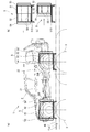
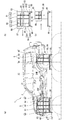
- FIG. 1 is a schematic diagram of the safety fence provided to the vehicle testing apparatus according to the embodiment of the present invention, (b) is an explanatory diagram of the safety fence being closed, and (c) is an explanation of the safety fence being open.
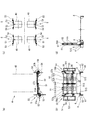
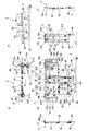
- Figure. (A) is a schematic plan view of the safety fence according to the first embodiment of the present invention, (b) is a front view of the safety fence, (c) is a plan view showing an example of the arrangement of the safety fence, and (d) is the plan The side view of a safety fence.
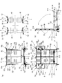
- (A) is a schematic plan view of a safety fence according to Embodiment 2 of the present invention
- (b) is a front view of the safety fence
- (c) is a plan view showing an example of the arrangement of the safety fence
- (d) is the plan The side view from the one end side of the fixed fence part of a safety fence.
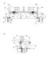
- (A) is a schematic configuration diagram of a clamp lever for fixing a safety fence
- (b) is an explanatory diagram of a state in which the safety fence is fixed by the clamp lever
- (c) is a clamp lever attached to a nut built in a pit. Explanatory drawing of the state by which the long screw was screwed through the insertion pipe and the washer.
- A is a front view of the roller side bending part with which the safety fence of Embodiment 2 was equipped,
- (b) is a side view of the said roller side bending part.
- (A) is a schematic diagram of the safety fence provided to the vehicle testing apparatus in Embodiment 3 of the present invention,
- (b) is an explanatory diagram of the safety fence being closed, and
- (c) is an explanation of the safety fence being open. Figure.
- (A) is the schematic diagram which showed the example 1 of the aspect of the safety fence provided to the vehicle test apparatus in Embodiment 4 of this invention, (b) is explanatory drawing of operation
- (A) is the front view which showed the example 2 of the safety fence in Embodiment 4 of this invention, (b) is a top view of the said safety fence, (c) is the side view of the one end side of the said safety fence, (d ) Is a side view of the other end of the safety fence in a folded state, (e) is a side view of the other end of the safety fence in an unfolded state, and (f) is a lower side of the safety fence. Rear view. The top view explaining the state where the test vehicle was restrained in the vehicle test apparatus.
- the vehicle test apparatus 1 according to the first embodiment of the present invention illustrated in FIGS. 1 and 2 includes a pit cover 4 that exposes a roller 3 on which a wheel 20 of the test vehicle 2 is placed from a roller opening 40, and a test vehicle. 2 is provided with a safety fence 5 disposed substantially in parallel with the wheels (front wheel 20F, rear wheel 20R).
- the safety fence 5 is attached to the pit cover 4 along one edge of the roller opening 40 corresponding to each wheel 20 of the test vehicle 2 of FIG.
- the safety fence 5 includes a fixed fence part 51, a slide fence part 52, a first folding fence part 53, and a second folding fence part 54.
- the fixed fence 51 is arranged substantially in parallel with the wheels 20 of the test vehicle 2.
- the fixed fence 51 includes a frame 511 made of an aluminum frame, a welded wire mesh 512 incorporated in the frame 511, and a fixed fence support 513 made of an aluminum frame that supports the frame 511 upright. Further, the fixed fence portion 51 includes a third hand knob 514 that presses and fixes the slide fence portion 52 to the frame body 511, and a handle 516 for carrying the safety fence 5.
- the fixed fence portion 51 includes a first angle adjustment panel 57a that defines the rotation range of the first folding fence portion 53 as shown in FIG. As shown in FIG. 5, the first angle adjustment board 57a is inserted with the rotating shaft of the first hand knob 58a for fixing the first folding fence 53 to the first angle adjustment board 57a.
- An arc-shaped long hole 571a that defines the rotation range of the fence 53 from a position parallel to the fixed fence 51 to a position of 270 degrees in the horizontal direction is formed.
- the slide fence 52 is arranged in parallel with the fixed fence 51 so as to face the test vehicle 2 inside the fixed fence 51 and move in the front-rear direction of the test vehicle 2.
- the slide fence portion 52 extends from the front side to the rear side position of the front wheel 20F shown in FIG. It is arranged to be movable toward the center of the test vehicle 2 within the range.
- the slide fence portion 52 moves forward from the rear side of the rear wheel 20R as shown in FIGS. 1 (a) to 1 (c). It is arranged so as to be movable toward the center of the test vehicle 2 in the range up to the position close to it.
- the slide fence portion 52 also has a frame body 521 made of an aluminum frame and a welded wire mesh 522 incorporated in the frame body 521, similarly to the fixed fence portion 51.
- the slide fence 52 is also provided with a second angle adjustment panel 57b that defines the rotation range of the second folding fence 54 as shown in FIG.
- the second angle adjustment board 57b is also inserted with the rotation axis of the second hand knob 58b for fixing the second folding fence part 54 to the second angle adjustment board 57b.
- An arc-shaped long hole 571b is defined that defines the rotation range of the portion 54 from a position parallel to the slide fence portion 52 to a position of 270 degrees in the horizontal direction.
- the first bent fence portion 53 is attached to one end portion of the fixed fence portion 51 so as to be rotatable inside and outside the fixed fence portion 51 by a hinge portion 56. It is done.
- the 1st bending fence part 53 has the frame 531 which consists of aluminum frames. Similarly to the fixed fence 51 and the slide fence 52, a welding wire mesh (not shown) is appropriately incorporated in the frame 531.
- the 1st bending fence part 53 is press-fixable by the 1st hand knob 58a in the 1st arbitrary positions prescribed
- the second bent fence portion 54 is attached to one end portion of the slide fence portion 52 so as to be rotatable inside and outside the slide fence portion 52 by a hinge portion 56.
- the second bent fence portion 54 has a frame body 541 made of an aluminum frame. Also in the frame body 541, similarly to the fixed fence portion 51 and the slide fence portion 52, a welding wire mesh (not shown) is appropriately incorporated.
- the 2nd bending fence part 54 is also in the 2nd arbitrary position prescribed
- the hand knob 58b can be pressed and fixed.
- the safety fence 5 can be attached to and detached from the pit cover 4 by a fixture 6.
- the pedestal 515 of the fixed fence support 513 is fixed to the pit cover 4 by the fixture 6.
- the fixture 6 includes a nut 61, an insertion pipe 62, a long screw 63, a washer 64, and a clamp lever 65.
- the nut 61 is disposed and fixed in the pit 41 below the pit cover 4.
- the insertion pipe 62 presses the pedestal portion 515 of the fixed fence portion support 513 against the pit cover 4 by the flange portion 621 while incliningly contacting the fixed nut 61.
- the long screw 63 is screwed onto the nut 61 while being inserted into the insertion pipe 62.
- the clamp lever 65 presses the flange portion 621 of the plug-in pipe 62 through the washer 64 while being attached to the upper end of the long screw 63.
- the test vehicle 2 shown in FIG. 1 is arranged on the pit 41.
- the safety fence 5 may be attached to or removed from the pit cover 4.
- the fixed fence portion support 513 of the safety fence 5 is fixed at a predetermined position on the pit cover 4 by the fixture 6 as shown in FIG.
- the insertion pipe 62 penetrates the pedestal 515 of the fixed fence support 513 as shown in FIG. 2, and the lower end of the insertion pipe 62 shown in FIG.
- the nut 61 is inserted into the pit 41 while being in contact with the upper end of the nut 61 fixedly.
- the long screw 63 inserted through the washer 64 and the insertion pipe 62 is screwed to the nut 61 by the operation of the clamp lever 65.
- the pedestal portion 515 of the fixed fence portion support 513 is pressed by the clamp lever 65 via the washer 64 and the flange portion 621 of the insertion pipe 62, and the fixed fence portion support 513 is attached to the pit cover 4.
- the fixed fence portion support 513 is quickly fixed to the pit cover 4. Is done.
- the safety fence 5 is arranged and fixed along one edge of the roller opening 40 of the pit cover 4 as shown in FIG.
- the fixed fence portion 51 is arranged at a position closer to the front of the front wheel 20F of the test vehicle 2, while the slide fence portion 52 is Inside the fixed fence part 51, it arrange
- the fixed fence 51 is arranged at a position behind the rear wheel 20R, while the slide fence 52 is fixed. Inside the part 51, it arrange
- the front door 21 may interfere with the second folding fence portion 54 of the safety fence 5.
- the second folding fence portion 54 is an arbitrary outside of the slide fence portion 52 as shown in FIGS. After being rotated to a position or a position along the outer surface of the slide fence portion 52, it is fixed by the second hand knob 58b.
- the slide fence portion 52 is fixed by the third hand knob 514 after being slid to an arbitrary position on the front side of the test vehicle 2. Thereby, interference with the front side door 21 and the 2nd bending fence part 54 of the safety fence 5 is avoided.
- the rear door 22 may interfere with the second bent fence portion 54 of the safety fence 5.
- the second folding fence portion 54 is located outside the slide fence portion 52 as shown in FIGS.
- the first hand knob 58a after being rotated to the position along the outer surface of the slide fence 52.
- the slide fence portion 52 is fixed by the third hand knob 514 after being slid to an arbitrary position on the rear side of the test vehicle 2.
- the first bent fence portion 53 and the second bent fence portion 54 of the safety fence 5 are fixed substantially in parallel with the test vehicle 2 side or the test vehicle 2. Thus, the entry of a person into the gap between the safety fence 5 and the test vehicle 2 is avoided.
- the slide fence 52 of the rear safety fence 5 is slid to an arbitrary position on the front side of the test vehicle 2 as shown in FIG. Then, it is fixed by the third hand knob 514.
- the fixed fence portion 51 is disposed substantially in parallel with the front wheel 20F at a position near the front of the front wheel 20F of the test vehicle 2.
- the slide fence portion 52 is movable toward the center side of the test vehicle 2 from a position parallel to the fixed fence portion 51 facing the test vehicle 2 shown in FIG. It can be arranged in a range from the front side to the rear side. Accordingly, the test vehicle 2 of various sizes can be flexibly handled and the degree of freedom is further expanded.
- the fixed fence portion 51 is disposed substantially parallel to the rear wheel 20R at a position near the rear of the rear wheel 20R of the test vehicle 2.
- the slide fence 52 can be moved from the position parallel to the fixed fence 51 facing the test vehicle 2 shown in FIGS. 1A and 1C toward the center of the test vehicle 2.
- the rear wheel 20R can be arranged in the range from the rear side to the front side. Accordingly, the test vehicle 2 of various sizes can be flexibly handled and the degree of freedom is further expanded.
- the first folding fence 53 can be fixed at an arbitrary position from a position parallel to the fixed fence 51 to a position of 270 degrees in the horizontal direction.
- the 2nd bending fence part 54 can be fixed in the arbitrary positions from the position parallel to the slide fence part 52 to the position of 270 degree
- the slide fence part 52 is guided to the front-back direction of the test vehicle 2 by the slide rail 55 interposed between the fixed fence part 51 and the slide fence part 52, the slide operation of the slide fence part 52 becomes smooth.
- the slide fence 52 can be fixed to the fixed fence 51 by the third hand knob 514, the slide fence 52 can be fixed at an arbitrary position in the width direction of the safety fence 5 according to the specifications of the test vehicle 2.
- the safety fence 5 is mainly made of an aluminum frame and is relatively light and compact. Therefore, it is easier to remove than the conventional safety fence at the time of maintenance, and the handle 516 makes it easier to carry. .
- the safety fence 5 is not limited to being attached to the pit cover 4 and may be attached to the roller cover of the roller 3. Also according to this aspect, the above-described effects can be obtained, and entry of people into the space between the test vehicle 2 and the safety fence 5 can be prevented.
- the safety fence 5 can be applied to the existing vehicle test apparatus.
- the safety fence 5 can be quickly and firmly attached to the pit cover 4 or the roller cover by the fixture 6.
- the safety fence 5 of Embodiment 2 illustrated in FIG. 3 has a function of simply covering the roller opening 40 in the safety fence 5 of Embodiment 1.
- the safety fence 5 of this embodiment is Embodiment 1 except that the roller opening 40 can be covered by the fixed fence portion 51 and the slide fence portion 52 and the fixed fence portion 51 can be arranged horizontally.
- the safety fence 5 is substantially the same mode.
- the safety fence 5 includes a fixed fence 51, a slide fence 52, a first bent fence 53, a second bent fence 54, and a roller side. A bent portion 7 is provided.
- the fixed fence 51 and the slide fence 52 are configured such that the horizontal dimension of the fixed fence 51 and the slide fence 52 is larger than the size of the roller opening 40.
- a welded wire mesh 532 is incorporated in the frame body 531 of the first bent fence portion 53, and a base rubber 533 that supports the first bent fence portion 53 in which the fixed fence portion 51 is disposed horizontally on the pit cover 4 is provided. Is provided.
- a welded wire mesh 542 is also incorporated in the frame body 541 of the second bent fence portion 54 and a base rubber 543 that supports the second bent fence portion 54 in which the slide fence portion 52 is horizontally arranged on the pit cover 4. Is provided.
- the roller side bent portion 7 includes a support portion 71, a catch clip 72, and a hinge portion 73.
- the support part 71 is disposed on the fixed fence part support 513 and supports the fixed fence part 51 upright.
- the catch clip 72 connects the support part 71 and the fixed fence part support body 513 so that the upright state of the fixed fence part 51 can be released.
- the hinge part 73 connects the support part 71 and the fixed fence part support body 513 so that the fixed fence part 51 can stand upright or can fall to the roller opening 40 side.
- the roller opening 40 is covered with the safety fence 5.
- the connected state of the support part 71 and the fixed fence part support body 513 that uprightly supports the fixed fence part 51 is released by the operation of the catch clip 72 of the roller side bent part 7.
- the fixed fence part 51 by the hinge part 73 of the roller side bending part 7 can fall to the roller opening part 40 side.
- first bent fence part 53 and the second bent fence part 54 are arranged side by side with the fixed fence part 51 and the slide fence part 52 being fixed to the test vehicle 2 side at a position of 90 °.
- the slide fence 52 is overturned to the roller opening 40 side.
- the roller opening 40 of the pit cover 4 is simply covered when the test vehicle 2 is not subjected to the test. be able to. Accordingly, since the roller opening 40 is not directly touched by the safety fence 5, an accident such as a person falling into the roller opening 40 or a person's foot entering the gap between the pit cover 4 and the roller 3. Can be prevented.
- the fixed fence portion 51 can cover the roller opening 40 and can be disposed substantially horizontally at a position corresponding to the roller opening 40, and thus covers the roller opening 40 simply and reliably. Can do. Further, the first bent fence portion 53 and the second bent fence portion 54 can support the fixed fence portion 51 arranged substantially horizontally by the pit cover 4 simply and firmly. Therefore, it is not necessary to separately prepare a cover for shielding the roller opening 40.
- the safety fence 5 of this aspect includes a fixed fence part 81, a first slide fence part 82, a second slide fence part 83, a third slide fence part 84, a first folding fence part 85, and a second folding fence part 86. Prepare.
- the fixed fence 81 is arranged substantially in parallel with the wheels (front wheel 20F, rear wheel 20R) of the test vehicle 2 placed on the roller 3 exposed from the roller opening 40 of the pit cover 4.
- the fixed fence portion 81 holds the frame 511 in a state where it is erected on a rectangular frame 811 made of steel, a welded wire mesh 812 incorporated in the frame 811, and a support 80 attached to the pit cover 4. And an L-shaped frame body support portion 813 which is supported at a height position.
- the first slide fence portion 82 is arranged in parallel with fixed fence part 81 so that movement in the front-back direction of test vehicle 2 is possible.
- the first slide fence portion 82 includes a frame body 821 that is substantially the same shape as the frame body 811, and a welded wire mesh 822 that is incorporated into the frame body 821.
- the first slide fence portion 82 is in the range of the width of the first slide fence portion 82 from the position where the first slide fence portion 82 is parallel to the fixed fence portion 81.
- a pair of slide rails 87 for guiding in the front-rear direction are provided.
- the second slide fence 83 is movable in the vertical direction of the test vehicle 2 and can be arranged in parallel with the fixed fence 81 and the first slide fence 82.
- the second slide fence portion 83 includes a rectangular frame body 831 made of a steel material similarly to the frame body 811, and a welding wire mesh 832 incorporated in the frame body 831.
- the second slide fence portion 83 is in a range of the length of the vertical side of the second slide fence portion 83 from a position where the second slide fence portion 83 is arranged in parallel with the fixed fence portion 81.
- a pair of slide rails 88 for guiding in the vertical direction is provided.
- the third slide fence portion 84 is movable in the vertical direction and can be arranged in parallel with the fixed fence portion 81, the first slide fence portion 82, and the second slide fence portion 83.
- the third slide fence portion 84 includes a frame body 841 that is substantially the same shape as the frame body 821 of the first slide fence portion 82, and a welded wire mesh 842 that is incorporated into the frame body 841.
- the length of the vertical side of the third slide fence part 84 from the position where the third slide fence part 84 is juxtaposed with the first slide fence part 82 is provided.
- a pair of slide rails 88 for guiding in the vertical direction within the range is provided.
- the first bent fence portion 85 has the same configuration as the first bent fence portion 53 of the first embodiment, and is attached to one end portion of the fixed fence portion 81 so as to be rotatable inside and outside the fixed fence portion 81. It has been.
- the second bent fence portion 86 has the same configuration as the second bent fence portion 54 of the first embodiment, and is capable of rotating inside and outside the first slide fence portion 82. Attached to one end.
- the vehicle restraint device 10 includes a hub connecting portion 11 attached to a wheel hub of the wheel 20 of the test vehicle 2, a wheel hub rod 12 rotatably connected to the hub connecting portion 11, And a fixed rod 13 rotatably connected to the vicinity of the end of the wheel hub rod 12 on the hub connecting portion 11 side.
- the wheel hub rod 12 and the fixed rod 13 are held by a rod holding portion 14 installed at an arbitrary position on the slide rail 42 of the vehicle test apparatus 1 as shown in FIG.
- the safety fence 5 is fixed to the pit cover 4 by a clamp lever 65 (not shown), so that the safety fence 5 is attached to the pit cover 4 as shown in FIGS. Arranged along one edge of the roller opening 40.
- the fixed fence portion 81 is located at the front side of the front wheel 20F of the test vehicle 2. Arranged.
- the fixed fence 81 is arranged at a position closer to the rear of the rear wheel 20R.
- the second slide fence part 83 and the third slide fence part 84 are respectively slid upward to the fixed fence part 81 and the first slide fence part 82 side, while the first slide The fence part 82 is slid to the fixed fence part 81 side.
- the safety fence 5 is changed from the form of FIG. 7B to the form of FIG. 7C, and the first slide fence part 82, the second slide fence part 83, and the third slide fence part 84 are connected to the fixed fence part 81. It becomes the state arranged in parallel.
- the hub connecting portion 11 of the vehicle restraint device 10 is attached to the wheel hub of the wheel 20 of the test vehicle 2, and the wheel hub rod 12 is connected to the hub connecting portion 11.
- a fixed rod 13 is connected in advance near the end of the wheel hub rod 12.
- the wheel hub rod 12 and the fixed rod 13 are held by the rod holding portion 14 installed at an arbitrary position on the slide rail 42 of the vehicle test apparatus 1.
- the first slide fence portion 82, the second slide fence portion 83, and the third slide fence portion 84 are each arbitrarily operated by sliding operation when the vehicle doors (front door 21 and rear door 22) of the test vehicle 2 are opened and closed.
- the test vehicle 2 can be moved in the front-rear direction and the up-down direction. Therefore, interference with the vehicle door is avoided. Therefore, the open / close range of the vehicle door of the test vehicle 2 provided to the vehicle test apparatus 1 can be expanded.
- the first slide fence portion 82, the second slide fence portion 83, and the third slide fence portion 84 can be arranged in parallel with the fixed fence portion 81 by a slide operation.
- An empty space is secured in the lower part of 5 (in particular, the lower part of the fixed fence part 81).
- the safety fence of the present invention provided with the slide fence portion is not limited to the third embodiment, and an appropriate form is adopted according to various vehicle test devices, vehicle restraint devices, and vehicle test system modes.
- the safety fence 5 including the fixed fence part 81, the first slide fence part 82, the second slide fence part 83, the first folding fence part 85, and the second folding fence part 86
- the safety fence 5 provided with the fixed fence part 81, the 1st slide fence part 82, the 3rd slide fence part 84, the 1st bending fence part 85, and the 2nd bending fence part 86 is mentioned.
- Example of safety fence 5 As shown in FIGS. 8 and 10, the safety fence 5 is attached to the pit cover 4 along one edge of the roller opening 40 corresponding to each wheel 20 of the test vehicle 2 shown in FIG. . Specific examples 1 and 2 of the safety fence 5 will be described below.
- the safety fence 5 of the example 1 shown by FIG. 8 is the fixed fence part 91, the 1st folding movable fence part 92, the 2nd folding movable fence part 93, the 1st folding fence part 96, and the 2nd folding fence part. 97.
- the fixed fence 91 is arranged substantially in parallel with the wheels (front wheel 20F, rear wheel 20R) of the test vehicle 2 placed on the roller 3 exposed from the roller opening 40 of the pit cover 4.
- the fixed fence portion 91 is erected and supported by a support body 50 attached to the pit cover 4.
- the first folding movable fence 92 is attached to one end of the fixed fence 91 so as to be rotatable outside the fixed fence 91 as shown in FIG.
- the second folding movable fence portion 93 is attached to one end portion of the first folding movable fence portion 92 so as to be rotatable outside the first folding movable fence portion 92.
- the first bent fence portion 96 is attached to one end portion of the fixed fence portion 91 so as to be rotatable inside and outside the fixed fence portion 91.
- the second folding fence part 97 is attached to one end of the second folding movable fence part 93 so as to be rotatable inside and outside the second folding movable fence part 93.
- the safety fence 5 of the aspect example 2 includes a fixed fence 91, a first folding movable fence 92, a second folding movable fence 93, a third folding movable fence 94, and a fourth folding movable.
- the fence part 95, the 1st bending fence part 96, the 2nd bending fence part 97, the 1st support member 98, and the 2nd support member 99 are provided.
- the fixed fence portion 91 is disposed substantially in parallel with the wheel 20 of the test vehicle 2 placed on the roller 3 exposed from the roller opening 40 of the pit cover 4.
- the fixed fence 91 is attached to the pit cover 4 and a substantially square frame 911 made of steel, a welded wire mesh 912 incorporated in the frame 911, and the pit cover 4. And an L-shaped frame body support portion 913 that supports the frame body 911 at a predetermined height while standing on the support body 90.
- the fixed fence portion 91 is provided with a handle 914 for carrying the safety fence 5 and a first angle adjusting panel 97a for defining the rotation range of the first folding fence portion 96.
- the first angle adjusting panel 97a has a length through which the rotation shaft of the first hand knob 98a for fixing the first folding fence portion 96 to the first angle adjusting panel 97a is inserted.
- a hole 971a is formed.
- the long hole 571a is formed in an arc shape so as to define the rotation range of the first bent fence portion 96 from a position parallel to the fixed fence portion 91 to a position of 270 degrees in the horizontal direction.
- the first folding movable fence portion 92 is attached to one end portion of the fixed fence portion 91 so as to be rotatable outside the fixed fence portion 91.
- the first folding movable fence portion 92 includes a rectangular frame body 921 that is vertically longer and narrower than the frame body 911 of the fixed fence portion 91, and a welded wire mesh 922 incorporated in the frame body 921.
- the frame body 921 is coupled to the frame body support part 913 of the fixed fence part 91 via the hinge part 60 so as to be rotatable outside the fixed fence part 91.
- the second folding movable fence part 93 is attached to one end of the first folding movable fence part 92 so as to be rotatable outside the first folding movable fence part 92.
- the second folding movable fence portion 93 has a frame body 931 having the same specifications as the frame body 911, a welding wire mesh 932 having the same specifications as the welding wire mesh 912, and the frame body 931 in a state of being erected on the support body 90.
- a frame body support portion 933 is provided which is supported at a position (the same height as the frame body 911).
- the frame body support portion 933 is configured to have the same specifications as the frame body support portion 913, and is one end of the frame body 921 of the first folding movable fence portion 92 so as to be rotatable to the outside of the first folding movable fence portion 92. Are connected to each other via a hinge part 60.
- the second folding movable fence part 93 is provided with a handle 934 for carrying the safety fence 5 and a second angle adjusting panel 97b for defining the rotation range of the second folding fence part 97.
- the second angle adjusting plate 97b is inserted with the rotation axis of the second hand knob 98b for fixing the second bent rail 97 to the second angle adjusting plate 97b.
- a hole 971b is formed.
- the long hole 971b is formed in an arc shape so as to define the rotation range of the second folding fence 97 from the position parallel to the second folding movable fence 93 to the position of 270 degrees in the horizontal direction.
- the third folding movable fence portion 94 is attached to the lower end portion of the fixed fence portion 91 so as to be arranged in parallel with the fixed fence portion 91.
- the third folding movable fence portion 94 includes a substantially square frame body 941 that can be disposed between the frame body 911 and the frame body support portion 913 of the fixed fence portion 91, and a welded wire mesh 942 incorporated in the frame body 941. Prepare.
- the frame body 941 is formed in substantially the same shape as the frame body 911 of the fixed fence portion 91, and is pivoted to the frame body 911 of the fixed fence portion 91 via the hinge portion 60 so as to be rotatable outside the fixed fence portion 91. Connected.
- the fourth folding movable fence portion 95 is attached to the lower end portion of the second folding movable fence portion 93 so as to be arranged in parallel with the second folding movable fence portion 93.
- the fourth folding movable fence portion 95 includes a substantially square frame body 951 that can be disposed between the frame body 931 and the frame body support portion 933 of the second folding movable fence portion 93, and a welded wire mesh incorporated in the frame body 951. 952.
- the frame body 951 is connected to the frame body 931 via the hinge part 60 so that the frame body 951 can be arranged in parallel with the frame body 931 of the second folding movable fence part 93 by rotating in the vertical direction.
- the 1st bending fence part 96 is attached to the one end part of the fixed fence part 91 so that rotation to the inner side and the outer side of the fixed fence part 91 is possible.
- the first bent fence 96 includes a rectangular frame 961 that is shorter and narrower than the frame 911 of the fixed fence 91, a welded wire mesh 962 that has the same specifications as the fixed fence 91, and a long side of the frame 961.
- a connecting member 963 is provided.
- the connecting member 963 is connected to one end of the frame body 911 through the hinge part 60.
- a first hand knob 98a can be screwed to the upper end portion of the connecting member 963 via a first angle adjustment board 97a.
- the second folding fence part 97 is attached to one end of the second folding movable fence part 93 so as to be rotatable inside and outside the second folding movable fence part 93.
- the second folding fence 97 includes a rectangular frame 971 that is shorter and narrower than the frame 931 of the second folding movable fence 93, a welded wire mesh 972 that has the same specifications as the fixed fence 91, and a frame 971.
- the connecting member 973 is provided along the long side.
- the connecting member 973 is connected to one end of the frame body 931 through the hinge part 60.
- a second hand knob 98b can be screwed to the upper end portion of the connecting member 973 via a second angle adjusting plate 97b.
- the second folding movable fence portion 93 and the fixed fence portion 91 are arranged in parallel on either the first angle adjustment plate 97a or the second angle adjustment plate 97b.
- a connecting member 101 for connecting the first angle adjusting board 97a and the second angle adjusting board 97b is attached.
- the first support member 98 supports the fixed fence portion 91 on the support 90 on the side surface of the support 90 in an auxiliary manner substantially in parallel.
- the first support member 98 is made of a substantially L-shaped plate-shaped steel material (for example, stainless steel) attached to the same plane side surfaces of the support 90 and the frame support 913. .
- the second support member 99 can support the first folding movable fence 92, the second folding movable fence 93, and the fourth folding movable fence 95 in series with respect to the fixed fence 91 on the upper surface of the support 90.
- the second support member 99 is a rectangular plate attached to the support 90, the frame 921, and the frame support 933 so as to be movable in the vertical direction as shown in FIG. Made of steel material (stainless steel).
- the second support member 99 is connected to the support 90. It is fixed to the side surfaces of the frame body 921 and the frame body support portion 933 by a fixture 991 such as a bolt.
- the 2nd support member 99 is the frame 921 and the frame. At a position below the body support portion 933, it is fixed to the side surface of the support body 90 by a fixture 991.
- the vehicle restraint device 10 includes a hub connecting portion 11 attached to a wheel hub of the wheel 20 of the test vehicle 2, a wheel hub rod 12 rotatably connected to the hub connecting portion 11, And a fixed rod 13 rotatably connected to the vicinity of the end of the wheel hub rod 12 on the hub connecting portion 11 side.
- the wheel hub rod 12 and the fixed rod 13 are held by a rod holding portion 14 installed at an arbitrary position on the slide rail 42 of the vehicle test apparatus 1 as shown in FIG.
- the test vehicle 2 is arranged on the pit 41 as shown in FIG.
- the safety fence 5 may be attached to or removed from the pit cover 4.
- the support 90 of the safety fence 5 is fixed at a predetermined position on the pit cover 4 as shown in FIG. Arranged and fixed along one edge of the roller opening 40 of the pit cover 4.
- the fixed fence portion 91 is arranged at a position closer to the front of the front wheel 20F of the test vehicle 2.
- the fixed fence portion 91 is disposed at a position closer to the rear of the rear wheel 20R.
- the third folding movable fence portion 94 is folded upward and arranged in parallel with the fixed fence portion 91.
- the fourth folding movable fence portion 95 is folded upward and arranged in parallel with the second folding movable fence portion 93.
- the second support member 99 shown in FIG. fixes to the side surface of the support body 90 with the fixing tool 991 in the position below the frame body support part 933. Accordingly, the first folding movable fence 92 and the second folding movable fence 93 can be folded to the outside of the fixed fence 91.
- the vehicle restraint device 10 can be connected to the wheel hub of the wheel 20 of the test vehicle 2.
- connection operation work of the vehicle restraint apparatus 10 is demonstrated.
- the hub connecting portion 11 of the vehicle restraint device 10 is attached to the wheel hub of the wheel 20 of the test vehicle 2, and the wheel hub rod 12 is connected to the hub connecting portion 11.
- the A fixed rod 13 is connected in advance near the end of the wheel hub rod 12.
- the wheel hub rod 12 and the fixed rod 13 are held by the rod holding portion 14 installed at an arbitrary position on the slide rail 42 of the vehicle test apparatus 1.
- the first folding movable fence 92 and the second folding are provided.
- the movable fence part 93 and the fourth folding movable fence part 95 are arranged in series with the fixed fence part 91.
- the second support member 99 is fixed to the side surfaces of the support body 90, the frame body 921, and the frame body support portion 933 by the fixture 991.
- the 1st folding movable fence part 92, the 2nd folding movable fence part 93, and the 4th folding movable fence part 95 will be in the state supported in series with the fixed fence part 91 stably.
- the safety fence 5 of the aspect example 1 is also attached to the pit cover 4 of the vehicle test apparatus 1 by the same attachment procedure as the safety fence 5 of the aspect example 2.
- the fixed fence portion 81 is disposed substantially parallel to the front wheel 20F at a position near the front of the front wheel 20F of the test vehicle 2. Further, in the safety fence 5 on the rear wheel 20R side, the fixed fence portion 81 is disposed substantially parallel to the rear wheel 20R at a position near the rear of the rear wheel 20R of the test vehicle 2. And the 1st folding movable fence part 92, the 2nd folding movable fence part 93, the 3rd folding movable fence part 94, and the 4th folding movable fence part 95 can be rotated outside the fixed fence part 91, and can be folded. It has become. Accordingly, the test vehicle 2 of various sizes can be flexibly handled and the degree of freedom is further expanded.
- the safety fence 5 when a steel material such as an aluminum frame is adopted as the constituent material of the safety fence 5, the safety fence 5 can be configured relatively lightly and compactly, so that it is easier to remove than the conventional safety fence during maintenance. With the provision of 914 and 934, carrying becomes easy.
- the first folding movable fence part 92, the second folding movable fence part 93, the third folding movable fence part 94, and the fourth folding movable fence part 95 are arranged in parallel with the fixed fence part 91 by the folding operation. Since it can be arranged, an empty space is secured below the safety fence 5. In particular, an empty space is secured at the bottom of the fixed fence portion 81.
- the safety fence 5 is not limited to being attached to the pit cover 4 and may be attached to the roller cover of the roller 3. Also according to this aspect, the above-described effects can be obtained, and entry of people into the space between the test vehicle 2 and the safety fence 5 can be prevented.
- the safety fence 5 can be applied to an existing vehicle test apparatus.
- the safety fence 5 can be quickly and firmly attached to the pit cover 4 or the roller cover by the fixture 6.
- the safety fence of the present invention is not limited to the first and second embodiments, and various forms are adopted according to various vehicle test devices, vehicle restraint devices, and vehicle test system modes.
- the safety fence 5 including the fixed fence 91, the first folding movable fence 92, the second folding movable fence 93, and the fourth folding movable fence 95, the fixed fence 91, the first The safety fence 5 which consists of the folding movable fence part 92, the 2nd folding movable fence part 93, and the 3rd folding movable fence part 94 is mentioned.
Landscapes
- Engineering & Computer Science (AREA)
- General Engineering & Computer Science (AREA)
- Physics & Mathematics (AREA)
- General Physics & Mathematics (AREA)
- Mechanical Engineering (AREA)
- Refuge Islands, Traffic Blockers, Or Guard Fence (AREA)
Abstract
L'invention concerne une barrière de sécurité et un dispositif de test de véhicule équipé de cette dernière, ladite barrière permettant d'éviter d'interférer avec la porte du véhicule de test quelle que soit la taille du véhicule de test et sans restreindre les degrés de liberté de la disposition d'agencement de dispositifs périphériques compris dans le dispositif de test de véhicule. Ladite barrière de sécurité (5), comprise dans un dispositif de test de véhicule (1), comprend une section de barrière fixe (51), une section de barrière coulissante (52), une première section de barrière pliante (53) et une seconde section de barrière pliante (54). La section de barrière fixe (51) est agencée de manière sensiblement parallèle à la roue avant (20F) et à la roue arrière (20R) d'un véhicule de test (2) placé sur des rouleaux (3) exposés depuis une section d'ouverture de rouleau (40) d'un couvercle de fosse (4). La section de barrière coulissante (52) peut se déplacer dans la direction longitudinale du véhicule de test (2) à partir d'un état agencé parallèlement à la section de barrière fixe (51). La première section de barrière pliante (53) est fixée rotative à l'intérieur et à l'extérieur de la section de barrière fixe (51) au niveau d'une extrémité de la section de barrière fixe (51). La seconde section de barrière pliante (54) est fixée rotative à l'intérieur et à l'extérieur de la section de barrière coulissante (52) à une extrémité de la section de barrière coulissante (52).
Priority Applications (2)
| Application Number | Priority Date | Filing Date | Title |
|---|---|---|---|
| US16/975,456 US11060954B2 (en) | 2018-02-28 | 2019-02-14 | Safety fence and vehicle testing device |
| KR1020207023031A KR102231720B1 (ko) | 2018-02-28 | 2019-02-14 | 안전 펜스 및 차량시험장치 |
Applications Claiming Priority (4)
| Application Number | Priority Date | Filing Date | Title |
|---|---|---|---|
| JP2018034077 | 2018-02-28 | ||
| JP2018-034077 | 2018-02-28 | ||
| JP2018-142232 | 2018-07-30 | ||
| JP2018142232A JP6536727B1 (ja) | 2018-02-28 | 2018-07-30 | 安全柵及び車両試験装置 |
Publications (1)
| Publication Number | Publication Date |
|---|---|
| WO2019167630A1 true WO2019167630A1 (fr) | 2019-09-06 |
Family
ID=67144662
Family Applications (1)
| Application Number | Title | Priority Date | Filing Date |
|---|---|---|---|
| PCT/JP2019/005182 Ceased WO2019167630A1 (fr) | 2018-02-28 | 2019-02-14 | Barrière de sécurité et dispositif de test de véhicule |
Country Status (4)
| Country | Link |
|---|---|
| US (1) | US11060954B2 (fr) |
| JP (1) | JP6536727B1 (fr) |
| KR (1) | KR102231720B1 (fr) |
| WO (1) | WO2019167630A1 (fr) |
Families Citing this family (2)
| Publication number | Priority date | Publication date | Assignee | Title |
|---|---|---|---|---|
| AT519997B1 (de) * | 2017-05-26 | 2019-03-15 | Seibt Kristl & Co Gmbh | Ermittlung einer Fahrzeuglängsbeschleunigung am Prüfstand |
| JP6593500B1 (ja) | 2018-07-30 | 2019-10-23 | 株式会社明電舎 | 安全柵及び車両試験装置 |
Citations (5)
| Publication number | Priority date | Publication date | Assignee | Title |
|---|---|---|---|---|
| JPS5821844U (ja) * | 1981-08-04 | 1983-02-10 | トヨタ自動車株式会社 | 前輪駆動、後輪駆動兼用シヤシダイナモメ−タの床板装置 |
| JPH0511044U (ja) * | 1991-07-26 | 1993-02-12 | 株式会社明電舎 | 車両試験装置用安全棚 |
| JP2005024430A (ja) * | 2003-07-03 | 2005-01-27 | Toyota Motor Corp | シャシダイナモメータ用防音装置 |
| JP2010169485A (ja) * | 2009-01-21 | 2010-08-05 | Meidensha Corp | 車両試験装置の安全柵 |
| US20180003590A1 (en) * | 2016-07-01 | 2018-01-04 | Ford Motor Company Limited | Chock assembly |
Family Cites Families (7)
| Publication number | Priority date | Publication date | Assignee | Title |
|---|---|---|---|---|
| JPH03126617U (fr) | 1990-04-03 | 1991-12-20 | ||
| JPH0511044A (ja) | 1991-07-02 | 1993-01-19 | Toyo Commun Equip Co Ltd | 応答機監視装置 |
| JPH0826649A (ja) | 1994-07-08 | 1996-01-30 | Mitsubishi Denki Bill Techno Service Kk | 安全柵装置 |
| US8176677B1 (en) | 2008-02-27 | 2012-05-15 | Blackmon Iii Baron H | Automated guide rail apparatus |
| JP6467155B2 (ja) | 2014-07-16 | 2019-02-06 | 品川ロコー株式会社 | 台車兼用安全柵 |
| CN106706336B (zh) | 2016-12-22 | 2023-12-22 | 江苏金彭集团有限公司 | 一种电动车整车振动综合试验平台 |
| JP6536728B1 (ja) * | 2018-02-28 | 2019-07-03 | 株式会社明電舎 | 車両試験装置 |
-
2018
- 2018-07-30 JP JP2018142232A patent/JP6536727B1/ja active Active
-
2019
- 2019-02-14 KR KR1020207023031A patent/KR102231720B1/ko active Active
- 2019-02-14 US US16/975,456 patent/US11060954B2/en active Active
- 2019-02-14 WO PCT/JP2019/005182 patent/WO2019167630A1/fr not_active Ceased
Patent Citations (5)
| Publication number | Priority date | Publication date | Assignee | Title |
|---|---|---|---|---|
| JPS5821844U (ja) * | 1981-08-04 | 1983-02-10 | トヨタ自動車株式会社 | 前輪駆動、後輪駆動兼用シヤシダイナモメ−タの床板装置 |
| JPH0511044U (ja) * | 1991-07-26 | 1993-02-12 | 株式会社明電舎 | 車両試験装置用安全棚 |
| JP2005024430A (ja) * | 2003-07-03 | 2005-01-27 | Toyota Motor Corp | シャシダイナモメータ用防音装置 |
| JP2010169485A (ja) * | 2009-01-21 | 2010-08-05 | Meidensha Corp | 車両試験装置の安全柵 |
| US20180003590A1 (en) * | 2016-07-01 | 2018-01-04 | Ford Motor Company Limited | Chock assembly |
Also Published As
| Publication number | Publication date |
|---|---|
| US11060954B2 (en) | 2021-07-13 |
| KR20200102517A (ko) | 2020-08-31 |
| US20210018399A1 (en) | 2021-01-21 |
| JP2019152641A (ja) | 2019-09-12 |
| JP6536727B1 (ja) | 2019-07-03 |
| KR102231720B1 (ko) | 2021-03-25 |
Similar Documents
| Publication | Publication Date | Title |
|---|---|---|
| CN104204761B (zh) | 底盘测功机和打开和闭合底盘测功机的辊开口的方法 | |
| EP2490906A1 (fr) | Train de galets pour fermeture coulissante de véhicule | |
| WO2019167631A1 (fr) | Dispositif de test de véhicule | |
| JPH06286512A (ja) | 産業車両の座席装置 | |
| JP2019152641A (ja) | 安全柵及び車両試験装置 | |
| JP2012515102A (ja) | ウインドデフレクタ | |
| JP4900826B2 (ja) | ピットカバーの開閉装置 | |
| KR100530137B1 (ko) | 자동차의 연료탱크 충돌방지 장치 | |
| JP6593500B1 (ja) | 安全柵及び車両試験装置 | |
| JP2005145269A (ja) | 鉄道車両用床下カバー装置 | |
| EP2052897A3 (fr) | Structure de stockage pour un élément de couverture pour véhicule de type à toit coulissant et véhicule doté de celle-ci | |
| JP3176157U (ja) | オープンカータイプバス | |
| JP2797095B2 (ja) | 一軸シャシダイナモメータ | |
| JP7431124B2 (ja) | 車両拘束装置およびシャシーダイナモメータ | |
| KR101599633B1 (ko) | 자동차용 후드힌지 | |
| JP5830985B2 (ja) | シャシーダイナモメータ | |
| JPH0417742Y2 (fr) | ||
| CN211439853U (zh) | 一种汽车树脂尾门检测用定位装置 | |
| JP4755962B2 (ja) | 床用目地装置 | |
| JPH0613473Y2 (ja) | 車両の固定装置 | |
| KR100338147B1 (ko) | 차량의 슬라이드형 배터리 이동장치 | |
| KR101568344B1 (ko) | 4절 링크 레일을 이용한 자동차용 슬라이딩 도어장치 | |
| CN221970988U (zh) | 一种电轿厢门质量检测装置 | |
| JP3403686B2 (ja) | 車載梯子格納装置 | |
| JPH0741647Y2 (ja) | フードチェンジャ |
Legal Events
| Date | Code | Title | Description |
|---|---|---|---|
| 121 | Ep: the epo has been informed by wipo that ep was designated in this application |
Ref document number: 19761700 Country of ref document: EP Kind code of ref document: A1 |
|
| ENP | Entry into the national phase |
Ref document number: 20207023031 Country of ref document: KR Kind code of ref document: A |
|
| NENP | Non-entry into the national phase |
Ref country code: DE |
|
| 122 | Ep: pct application non-entry in european phase |
Ref document number: 19761700 Country of ref document: EP Kind code of ref document: A1 |