WO2019167839A1 - 熱交換器 - Google Patents
熱交換器 Download PDFInfo
- Publication number
- WO2019167839A1 WO2019167839A1 PCT/JP2019/006840 JP2019006840W WO2019167839A1 WO 2019167839 A1 WO2019167839 A1 WO 2019167839A1 JP 2019006840 W JP2019006840 W JP 2019006840W WO 2019167839 A1 WO2019167839 A1 WO 2019167839A1
- Authority
- WO
- WIPO (PCT)
- Prior art keywords
- heat transfer
- heat exchanger
- heat
- header
- transfer unit
- Prior art date
- Legal status (The legal status is an assumption and is not a legal conclusion. Google has not performed a legal analysis and makes no representation as to the accuracy of the status listed.)
- Ceased
Links
Images











Classifications
-
- F—MECHANICAL ENGINEERING; LIGHTING; HEATING; WEAPONS; BLASTING
- F28—HEAT EXCHANGE IN GENERAL
- F28D—HEAT-EXCHANGE APPARATUS, NOT PROVIDED FOR IN ANOTHER SUBCLASS, IN WHICH THE HEAT-EXCHANGE MEDIA DO NOT COME INTO DIRECT CONTACT
- F28D1/00—Heat-exchange apparatus having stationary conduit assemblies for one heat-exchange medium only, the media being in contact with different sides of the conduit wall, in which the other heat-exchange medium is a large body of fluid, e.g. domestic or motor car radiators
- F28D1/02—Heat-exchange apparatus having stationary conduit assemblies for one heat-exchange medium only, the media being in contact with different sides of the conduit wall, in which the other heat-exchange medium is a large body of fluid, e.g. domestic or motor car radiators with heat-exchange conduits immersed in the body of fluid
- F28D1/04—Heat-exchange apparatus having stationary conduit assemblies for one heat-exchange medium only, the media being in contact with different sides of the conduit wall, in which the other heat-exchange medium is a large body of fluid, e.g. domestic or motor car radiators with heat-exchange conduits immersed in the body of fluid with tubular conduits
- F28D1/053—Heat-exchange apparatus having stationary conduit assemblies for one heat-exchange medium only, the media being in contact with different sides of the conduit wall, in which the other heat-exchange medium is a large body of fluid, e.g. domestic or motor car radiators with heat-exchange conduits immersed in the body of fluid with tubular conduits the conduits being straight
- F28D1/0535—Heat-exchange apparatus having stationary conduit assemblies for one heat-exchange medium only, the media being in contact with different sides of the conduit wall, in which the other heat-exchange medium is a large body of fluid, e.g. domestic or motor car radiators with heat-exchange conduits immersed in the body of fluid with tubular conduits the conduits being straight the conduits having a non-circular cross-section
- F28D1/05366—Assemblies of conduits connected to common headers, e.g. core type radiators
- F28D1/05391—Assemblies of conduits connected to common headers, e.g. core type radiators with multiple rows of conduits or with multi-channel conduits combined with a particular flow pattern, e.g. multi-row multi-stage radiators
-
- F—MECHANICAL ENGINEERING; LIGHTING; HEATING; WEAPONS; BLASTING
- F28—HEAT EXCHANGE IN GENERAL
- F28F—DETAILS OF HEAT-EXCHANGE AND HEAT-TRANSFER APPARATUS, OF GENERAL APPLICATION
- F28F1/00—Tubular elements; Assemblies of tubular elements
- F28F1/10—Tubular elements and assemblies thereof with means for increasing heat-transfer area, e.g. with fins, with projections, with recesses
- F28F1/12—Tubular elements and assemblies thereof with means for increasing heat-transfer area, e.g. with fins, with projections, with recesses the means being only outside the tubular element
- F28F1/24—Tubular elements and assemblies thereof with means for increasing heat-transfer area, e.g. with fins, with projections, with recesses the means being only outside the tubular element and extending transversely
- F28F1/26—Tubular elements and assemblies thereof with means for increasing heat-transfer area, e.g. with fins, with projections, with recesses the means being only outside the tubular element and extending transversely the means being integral with the element
-
- F—MECHANICAL ENGINEERING; LIGHTING; HEATING; WEAPONS; BLASTING
- F28—HEAT EXCHANGE IN GENERAL
- F28D—HEAT-EXCHANGE APPARATUS, NOT PROVIDED FOR IN ANOTHER SUBCLASS, IN WHICH THE HEAT-EXCHANGE MEDIA DO NOT COME INTO DIRECT CONTACT
- F28D1/00—Heat-exchange apparatus having stationary conduit assemblies for one heat-exchange medium only, the media being in contact with different sides of the conduit wall, in which the other heat-exchange medium is a large body of fluid, e.g. domestic or motor car radiators
- F28D1/02—Heat-exchange apparatus having stationary conduit assemblies for one heat-exchange medium only, the media being in contact with different sides of the conduit wall, in which the other heat-exchange medium is a large body of fluid, e.g. domestic or motor car radiators with heat-exchange conduits immersed in the body of fluid
- F28D1/0246—Heat-exchange apparatus having stationary conduit assemblies for one heat-exchange medium only, the media being in contact with different sides of the conduit wall, in which the other heat-exchange medium is a large body of fluid, e.g. domestic or motor car radiators with heat-exchange conduits immersed in the body of fluid heat-exchange elements having several adjacent conduits forming a whole, e.g. blocks
-
- F—MECHANICAL ENGINEERING; LIGHTING; HEATING; WEAPONS; BLASTING
- F28—HEAT EXCHANGE IN GENERAL
- F28D—HEAT-EXCHANGE APPARATUS, NOT PROVIDED FOR IN ANOTHER SUBCLASS, IN WHICH THE HEAT-EXCHANGE MEDIA DO NOT COME INTO DIRECT CONTACT
- F28D1/00—Heat-exchange apparatus having stationary conduit assemblies for one heat-exchange medium only, the media being in contact with different sides of the conduit wall, in which the other heat-exchange medium is a large body of fluid, e.g. domestic or motor car radiators
- F28D1/02—Heat-exchange apparatus having stationary conduit assemblies for one heat-exchange medium only, the media being in contact with different sides of the conduit wall, in which the other heat-exchange medium is a large body of fluid, e.g. domestic or motor car radiators with heat-exchange conduits immersed in the body of fluid
- F28D1/04—Heat-exchange apparatus having stationary conduit assemblies for one heat-exchange medium only, the media being in contact with different sides of the conduit wall, in which the other heat-exchange medium is a large body of fluid, e.g. domestic or motor car radiators with heat-exchange conduits immersed in the body of fluid with tubular conduits
- F28D1/053—Heat-exchange apparatus having stationary conduit assemblies for one heat-exchange medium only, the media being in contact with different sides of the conduit wall, in which the other heat-exchange medium is a large body of fluid, e.g. domestic or motor car radiators with heat-exchange conduits immersed in the body of fluid with tubular conduits the conduits being straight
- F28D1/05316—Assemblies of conduits connected to common headers, e.g. core type radiators
- F28D1/05341—Assemblies of conduits connected to common headers, e.g. core type radiators with multiple rows of conduits or with multi-channel conduits combined with a particular flow pattern, e.g. multi-row multi-stage radiators
-
- F—MECHANICAL ENGINEERING; LIGHTING; HEATING; WEAPONS; BLASTING
- F28—HEAT EXCHANGE IN GENERAL
- F28F—DETAILS OF HEAT-EXCHANGE AND HEAT-TRANSFER APPARATUS, OF GENERAL APPLICATION
- F28F1/00—Tubular elements; Assemblies of tubular elements
- F28F1/10—Tubular elements and assemblies thereof with means for increasing heat-transfer area, e.g. with fins, with projections, with recesses
- F28F1/12—Tubular elements and assemblies thereof with means for increasing heat-transfer area, e.g. with fins, with projections, with recesses the means being only outside the tubular element
- F28F1/14—Tubular elements and assemblies thereof with means for increasing heat-transfer area, e.g. with fins, with projections, with recesses the means being only outside the tubular element and extending longitudinally
- F28F1/16—Tubular elements and assemblies thereof with means for increasing heat-transfer area, e.g. with fins, with projections, with recesses the means being only outside the tubular element and extending longitudinally the means being integral with the element, e.g. formed by extrusion
-
- F—MECHANICAL ENGINEERING; LIGHTING; HEATING; WEAPONS; BLASTING
- F28—HEAT EXCHANGE IN GENERAL
- F28F—DETAILS OF HEAT-EXCHANGE AND HEAT-TRANSFER APPARATUS, OF GENERAL APPLICATION
- F28F1/00—Tubular elements; Assemblies of tubular elements
- F28F1/10—Tubular elements and assemblies thereof with means for increasing heat-transfer area, e.g. with fins, with projections, with recesses
- F28F1/12—Tubular elements and assemblies thereof with means for increasing heat-transfer area, e.g. with fins, with projections, with recesses the means being only outside the tubular element
- F28F1/14—Tubular elements and assemblies thereof with means for increasing heat-transfer area, e.g. with fins, with projections, with recesses the means being only outside the tubular element and extending longitudinally
- F28F1/22—Tubular elements and assemblies thereof with means for increasing heat-transfer area, e.g. with fins, with projections, with recesses the means being only outside the tubular element and extending longitudinally the means having portions engaging further tubular elements
-
- F—MECHANICAL ENGINEERING; LIGHTING; HEATING; WEAPONS; BLASTING
- F28—HEAT EXCHANGE IN GENERAL
- F28D—HEAT-EXCHANGE APPARATUS, NOT PROVIDED FOR IN ANOTHER SUBCLASS, IN WHICH THE HEAT-EXCHANGE MEDIA DO NOT COME INTO DIRECT CONTACT
- F28D21/00—Heat-exchange apparatus not covered by any of the groups F28D1/00 - F28D20/00
- F28D2021/0019—Other heat exchangers for particular applications; Heat exchange systems not otherwise provided for
- F28D2021/0068—Other heat exchangers for particular applications; Heat exchange systems not otherwise provided for for refrigerant cycles
-
- F—MECHANICAL ENGINEERING; LIGHTING; HEATING; WEAPONS; BLASTING
- F28—HEAT EXCHANGE IN GENERAL
- F28F—DETAILS OF HEAT-EXCHANGE AND HEAT-TRANSFER APPARATUS, OF GENERAL APPLICATION
- F28F2270/00—Thermal insulation; Thermal decoupling
-
- F—MECHANICAL ENGINEERING; LIGHTING; HEATING; WEAPONS; BLASTING
- F28—HEAT EXCHANGE IN GENERAL
- F28F—DETAILS OF HEAT-EXCHANGE AND HEAT-TRANSFER APPARATUS, OF GENERAL APPLICATION
- F28F3/00—Plate-like or laminated elements; Assemblies of plate-like or laminated elements
- F28F3/12—Elements constructed in the shape of a hollow panel, e.g. with channels
-
- F—MECHANICAL ENGINEERING; LIGHTING; HEATING; WEAPONS; BLASTING
- F28—HEAT EXCHANGE IN GENERAL
- F28F—DETAILS OF HEAT-EXCHANGE AND HEAT-TRANSFER APPARATUS, OF GENERAL APPLICATION
- F28F9/00—Casings; Header boxes; Auxiliary supports for elements; Auxiliary members within casings
- F28F9/02—Header boxes; End plates
- F28F9/0202—Header boxes having their inner space divided by partitions
- F28F9/0204—Header boxes having their inner space divided by partitions for elongated header box, e.g. with transversal and longitudinal partitions
Definitions
- Some heat exchangers used in air conditioners and the like have a small-diameter heat transfer tube unit formed by pasting heat transfer fin plates (for example, Patent Document 1 (Japanese Patent Laid-Open No. 2006-90636)). Publication) etc.).
- frost formation may occur intensively in part due to the internal heat flux distribution. And an air path obstruction
- occlusion arises in the location where frost formation concentrated, and the performance of a heat exchanger may fall.
- the heat exchanger according to the first aspect is configured such that a plurality of heat transfer flow path portions and a plurality of heat transfer auxiliary portions extending in the first direction are formed side by side in a second direction that is inclined or orthogonal to the first direction.
- a plurality of heat transfer units are arranged in a third direction different from both the first direction and the second direction.
- the heat transfer unit is divided into an upwind region and a leeward region along the second direction.
- the heat exchanger according to the first aspect is used as an evaporator, the refrigerant flows into the heat transfer channel portion arranged in the windward region, and then the refrigerant is supplied to the heat transfer channel portion arranged in the leeward region. Spill. With such a configuration, the heat exchange performance of the entire heat exchanger can be optimized.
- the heat exchanger according to the second aspect is the heat exchanger according to the first aspect, wherein the number of heat transfer flow path portions arranged in the leeward area is more than the number of heat transfer flow path parts arranged in the windward area. There are many. With such a configuration, optimal heat exchange can be realized while suppressing frost formation.
- the heat exchanger according to the third aspect is the heat exchanger according to the first aspect or the second aspect, and further includes a decompression mechanism that decompresses the refrigerant.
- the heat exchanger of the 3rd viewpoint makes a refrigerant
- the heat exchanger according to the fourth aspect is the heat exchanger according to the first to third aspects, and is connected to the heat transfer unit from above and below along the first direction to form a part of the refrigerant flow path.
- An upper header and a lower header are further provided. With such a configuration, it is possible to realize a heat exchanger that easily discharges condensed water.
- the heat exchanger according to the fifth aspect is the heat exchanger according to the fourth aspect, wherein the windward area and the leeward area are formed by a partition member disposed inside the upper header and / or the lower header. is there. Therefore, the windward area and the leeward area can be easily formed.
- the heat exchanger according to the sixth aspect is the heat exchanger according to the first to fifth aspects, wherein each heat transfer unit has at least eight heat transfer channel portions, and at least two heat transfer channel portions. Are arranged in the windward region. With such a configuration, the heat exchange performance can be optimized.
- a heat exchanger according to a seventh aspect is a heat exchanger according to the first to sixth aspects, and a heat insulating material is applied to an end portion in the second direction of the heat transfer unit as viewed in the first direction. Therefore, a decrease in temperature at the end can be suppressed.
- the heat exchanger according to the eighth aspect is the heat exchanger according to the seventh aspect, and the heat transfer unit includes a first heat transfer unit that is one of heat transfer auxiliary portions at an end portion in the second direction as viewed in the first direction.
- a heat assisting part is formed. Moreover, it is the shape where the 1st heat-transfer auxiliary
- the air conditioner according to the ninth aspect is equipped with the heat exchanger according to the first to eighth aspects.
- FIG. 10 It is a schematic diagram which shows the cross-sectional shape of the heat exchanger 10 which concerns on the same embodiment. It is a figure for demonstrating the refrigerant
- FIG. 12 is a schematic diagram for explaining a configuration of a heat transfer unit group 15 according to Modification C.
- FIG. 12 is a schematic diagram for explaining a configuration of a heat transfer unit group 15 according to Modification C.
- FIG. 10 is a schematic diagram for explaining a configuration of a heat transfer unit group 15 according to Modification E.
- FIG. It is a schematic diagram for demonstrating the structure of the heat-transfer unit group 15 which concerns on the modification E (partial enlarged view of FIG. 16).
- 12 is a schematic diagram for explaining a configuration of a heat transfer unit group 15 according to Modification F.
- FIG. It is a schematic diagram for demonstrating the structure of the heat-transfer unit group 15 which concerns on the modification F (partial enlarged view of FIG. 18).
- the heat exchanger 10 performs heat exchange between a fluid flowing inside and air flowing outside. Specifically, as shown in FIG. 1, the heat exchanger 10 is provided with a first pipe 41 and a second pipe 42 for flowing in and out of the refrigerant. A fan 6 for sending air to the heat exchanger 10 is disposed in the vicinity of the heat exchanger 10. The fan 6 generates an air flow toward the heat exchanger 10, and heat exchange is performed between the heat exchanger 10 and the air when the air flow passes through the heat exchanger 10.
- the heat exchanger 10 functions both as an evaporator that takes heat away from the air and as a condenser (heat radiator) that releases heat to the air, and can be mounted on an air conditioner or the like.
- the heat exchanger 10 includes a heat transfer unit group 15, a first header 21, and a second header 22, as shown in FIG.
- the heat transfer unit group 15 includes a plurality of heat transfer units 30.
- the heat transfer unit group 15 is arranged so that the direction of the air flow generated by the fan 6 passes between the heat transfer units 30. Details of the arrangement of each member will be described later.
- the first header 21 is configured by a hollow member, and is configured so that a refrigerant in a gas / liquid / gas-liquid two-phase state can flow therethrough. .
- the first header 21 is connected to the heat transfer unit 30 above the heat transfer unit 30.
- a connection surface 21 ⁇ / b> S for connecting to the heat transfer unit 30 is formed on the lower surface of the first header 21.
- the connection surface 21S is formed with a connection hole into which an end portion 31e of a heat transfer channel portion 31 described later is inserted.
- FIG. 3 shows a cross-sectional shape of the first header 21 when viewed from the third direction D3. The definition of the third direction D3 will be described later.
- the second header 22 is connected to the first pipe 41 and the second pipe 42 and the heat transfer unit 30 below the heat transfer unit 30, and between the first pipe 41 and the second pipe 42 and the heat transfer unit 30. This allows the refrigerant to flow in and out.
- the second header 22 is formed of a hollow member, and is configured so that a refrigerant in a gas / liquid / gas-liquid two-phase state can flow therethrough.
- the second header 22 includes a partition member 22p that partitions the inside along the third direction D3. In the example of FIG. 4, for convenience, the second header 22 is divided into an upwind second header 22U and a downwind second header 22L by a partition member 22p.
- the upwind second header 22U and the downwind second header 22L are connected to the second header 22 and the first header 21, respectively.
- the partition member 22p may be formed integrally with the second header 22 or may be configured by a separate object.
- a connection surface 22 ⁇ / b> S for connecting to the heat transfer unit 30 is formed on the upper surface of the second header 22.
- the connection surface 22S is formed with a connection hole into which an end portion 31e of a heat transfer channel portion 31 described later is inserted.
- FIG. 4 shows the cross-sectional shape of the second header 22 when viewed from the third direction D3. The definition of the third direction D3 will be described later.
- the heat transfer unit 30 includes a plurality of heat transfer flow path portions 31 and a plurality of heat transfer auxiliary portions 32 extending in the “first direction D1” that are inclined or orthogonal to the first direction D1. It is formed side by side in the “second direction D2”.
- the heat transfer channel portion 31 has a substantially cylindrical shape
- the heat transfer auxiliary portion 32 has a substantially flat plate shape.
- the heat transfer flow path portions 31 are formed so as to be aligned at a predetermined pitch PP in the second direction D2.
- the heat transfer unit group 15 includes at least three heat transfer units 30 arranged in a stacked manner.
- the first direction D1, the second direction D2, and the third direction D3 are orthogonal to each other.
- these directions D1 to D3 are not completely orthogonal, it is possible to realize the heat exchanger 10 according to the present embodiment as long as they are inclined with respect to each other.
- the heat transfer unit 30 is connected to the first header 21 and the second header 22 at the connection surfaces 21 ⁇ / b> S and 22 ⁇ / b> S of the first header 21 and the second header 22. Specifically, as shown in FIG. 5, the end portion 31 e of the heat transfer flow path portion 31 protrudes from the end portion 32 e of the heat transfer auxiliary portion 32 at the end portion in the first direction D1 of the heat transfer unit 30. The end portion 31 e of the heat transfer channel portion 31 is inserted into a connecting hole provided in the connection surfaces 21 ⁇ / b> S and 22 ⁇ / b> S of the first header 21 and the second header 22. And this heat transfer unit 30 is fixed between the 1st header 21 and the 2nd header 22 by brazing etc. (refer FIG. 8).
- the heat transfer channel portion 31 enables the refrigerant to move between the first header 21 and the second header 22. Specifically, a substantially cylindrical passage is formed in the heat transfer flow path portion 31, and the refrigerant moves through the passage. In addition, the heat transfer flow path part 31 which concerns on this embodiment is formed in linear form along the 1st direction D1.
- the heat transfer auxiliary part 32 promotes heat exchange between the refrigerant flowing inside the adjacent heat transfer channel part 31 and the surrounding air.
- the heat transfer auxiliary part 32 is formed so as to extend in the first direction D ⁇ b> 1 similarly to the heat transfer flow path part 31, and is disposed so as to be in contact with the adjacent heat transfer flow path part 31.
- the heat transfer auxiliary part 32 may be formed integrally with the heat transfer channel part 31 or may be formed separately.
- At least eight or more heat transfer flow path portions 31 are formed. And at least 2 or more heat-transfer flow-path parts 31 are arrange
- FIG. 8 is a schematic diagram showing a cross-sectional shape when the heat exchanger 10 is viewed from the third direction D3.
- the refrigerant F exchanges heat with the air flow W while flowing through the heat transfer flow path portions 31U and 31L. Thereby, the refrigerant
- FIG. 10 the state when the heat-transfer unit 30 is seen from the 3rd direction D3 is shown.
- the refrigerant F flows in the opposite direction to that in the evaporator. That is, the gas-phase refrigerant F flows from the first pipe 41 and the liquid-phase refrigerant F flows out from the second pipe 42.
- the heat transfer unit 30 is manufactured from metal materials, such as aluminum or aluminum alloy, for example. Specifically, first, a metal material is extruded using a mold corresponding to the cross-sectional shape of FIG. 5, and the heat transfer channel portion 31 and the heat transfer auxiliary portion 32 are integrally formed. Subsequently, a part of the heat transfer auxiliary part 32 is cut away to provide a notch 33.
- the notch 33 is formed by, for example, cutting a plurality of locations of the heat transfer auxiliary portion 32 by punching.
- the first header 21 and the second header 22 are manufactured by processing a metal material into a tubular shape.
- the first header 21 and the second header 22 are provided with connection holes for inserting the end portions 31 e of the heat transfer flow path portions 31.
- the connection hole is a circular through hole formed by, for example, a drill.
- the end portion 31 e of the heat transfer channel portion 31 of the heat transfer unit 30 is inserted into the connection hole of the first header 21 and the second header 22.
- the end portion 32e of the heat transfer auxiliary portion 32 comes into contact with the connection surfaces 21S and 22S of the first header 21 and the second header 22.
- the heat transfer unit 30, the first header 21 and the second header 22 are fixed by brazing or the like.
- the plurality of heat transfer flow path portions 31 and the plurality of heat transfer auxiliary portions 32 extending in the first direction D1 are inclined or orthogonal to the first direction D1.
- the heat transfer unit 30 is formed side by side in the second direction D2.
- a plurality of heat transfer units 30 are arranged in a third direction D3 different from both the first direction D1 and the second direction D2, and form a heat transfer unit group 15.
- the heat transfer unit 30 is divided into the windward area WU and the leeward area WL along the second direction D2. And when the heat exchanger 10 is used as an evaporator, the refrigerant F flows into the heat transfer flow path portion 31U disposed in the windward area WU, and then the heat transfer flow path section 31L disposed in the leeward area WL. Let the refrigerant F flow out.
- the refrigerant flow path is folded at least once in the second direction D2 in which the air flow W is generated. Therefore, the heat exchanger excellent in heat exchange performance can be provided.
- the temperature is low (for example, 7 degrees Celsius).
- frost formation may occur between the heat transfer units 30Z because the heat transfer amount in the heat transfer passage section on the windward side is large.
- air passage blockage may occur due to frost formation.
- the partition member etc. are not provided in the inside of the 1st header 21Z and the 2nd header 22Z which are shown in FIG.
- the pressure of the refrigerant is limited by limiting the number of flow paths of the refrigerant F flowing from the second pipe 42 to the number of the upwind heat transfer flow path portions 31U. Loss occurs. Then, due to this pressure loss, the refrigerant temperature in the upwind heat transfer channel portion 31U increases. Therefore, when the heat exchanger 10 is used as an evaporator, the amount of heat exchange in the upwind heat transfer channel portion 31U is suppressed. Thereby, the fluctuation
- the heat exchange amount of the windward heat transfer channel portion is reduced to the leeward heat transfer channel portion due to the leading edge effect of the heat transfer auxiliary portion on the windward side.
- the amount of heat exchange increases. Therefore, when the refrigerant F flowing in from the second pipe 42 is caused to flow through the plurality of heat transfer flow path portions, the refrigerant F may be completely evaporated in the heat transfer flow path portion on the windward side. As a result, a situation may occur in which sufficient heat exchange is not performed in the heat exchanger 10Z.
- the heat exchanger 10 has a larger number of heat transfer channel portions 31L arranged in the leeward region WL than the number of heat transfer channel portions 31U arranged in the upwind region WU. is there.
- each heat transfer unit 30 has at least eight or more heat transfer channel portions 31, and at least two or more heat transfer channel portions 31U are arranged in the windward region WU.
- the heat exchanger 10 is connected to the heat transfer unit 30 from above and below along the first direction D1, and forms the first header 21 (upper header) and the second that form part of the refrigerant flow path.
- a header 22 (lower header) is further provided.
- the heat exchanger 10 does not exclude a configuration in which the first header 21 and the second header 22 are provided in the left-right direction instead of the up-down direction.
- the windward area WU and the leeward area WL are formed by the partition member 22p disposed inside the second header 22 (lower header). Therefore, the upwind area WU and the downwind area WL can be easily formed without performing special processing or the like on the heat transfer unit 30.
- the heat exchanger 10 may be provided with a partition member inside the first header 21 instead of the second header 22 according to the refrigerant flow path. Or you may provide a partition member in any of the 1st header 21 and the 2nd header 22 according to the distribution route of a refrigerant
- the heat exchanger 10 which concerns on this embodiment can form each heat-transfer unit 30 from a single member by extrusion molding of a metal material. Further, the plurality of notches 33 can be formed at a time by punching. Therefore, the heat exchanger 10 with high assemblability and workability can be provided.
- the heat exchanger 10 may further include a decompression mechanism that decompresses the refrigerant.
- the heat exchanger 10 has a refrigerant channel (heat transfer channel 31U) in the windward region WU and a refrigerant channel (heat transfer channel 31L) in the leeward region WL.
- a pressure reducing mechanism 25 constituted by an electric valve or the like may be provided therebetween.
- the refrigerant temperature in the windward region can be optimized by expanding the refrigerant F by the decompression mechanism 25.
- a low temperature environment for example, 7 degrees Celsius or less
- the heat exchanger 10 according to the present embodiment is not limited to the above configuration. That is, the heat exchanger 10 according to the present embodiment can adopt any form as long as the refrigerant flow path is folded at least once in the second direction D2 in which the air flow W is generated.
- a heat exchanger 10Y having a refrigerant flow path as shown in FIG. 13 may be used.
- FIG. 13 is a schematic diagram for explaining a refrigerant flow path formed inside the heat exchanger 10Y.
- a partition member 22ps is provided along the second direction D2 inside the windward second header 22U in the vicinity of the center of the windward second header 22U.
- the windward second header 22U is divided into two regions, the windward upstream second header 22UA and the windward downstream second header 22UB.
- the partition member 21p and the like are also provided inside the first header 21, and the first header 21 is connected to the upwind first header 21U and the downwind first along the second direction D2. It is divided into a header 21L.
- coolant F which flowed in into the windward upstream 2nd header 22UA from the 2nd piping 42 passes along the heat-transfer flow-path part of a windward upstream area, and windward 1st header It flows into 21U. Subsequently, the refrigerant F flows into the heat transfer flow path portion in the windward downstream region via the windward first header 21U. And the refrigerant
- the refrigerant flow path is folded at least once in the second direction D2 in which the air flow W is generated, so that the same effect as described above is realized. .
- the heat exchanger 10 has the heat insulating material I at the windward end (here, the heat transfer auxiliary portion 32g) in the second direction D2 of the heat transfer unit 30 when viewed from the first direction D1. May be applied (see FIGS. 14 and 15). Thereby, the fall of the temperature in the said edge part can be suppressed. As a result, when the heat exchanger 10 is used as an evaporator in a low temperature environment (for example, 7 degrees Celsius or less), frost formation can be suppressed and air passage blockage can be avoided or delayed.
- a low temperature environment for example, 7 degrees Celsius or less
- the end of the heat transfer unit 30 is the heat transfer auxiliary portion 32 g.
- the heat transfer auxiliary part 32g (first heat transfer auxiliary part) on the uppermost wind side has a closed shape.
- the “closed shape” means a flat shape with no holes or cuts. Thereby, the drainage property at the time of a defrost operation can further be improved.
- the heat transfer auxiliary portion 32g has a shape without a hole or a cut, so that frost formation after the defrosting operation can be suppressed.
- the heat transfer flow path part 31 which concerns on this embodiment is not restricted to what was mentioned above, Another form may be sufficient.
- the cross-sectional shape when the heat transfer channel portion 31 is viewed from the first direction D1 is any one of a semicircular shape, an elliptical shape, a flat shape, an airfoil upper half shape, and / or an airfoil lower half shape. Or any combination.
- the heat exchanger 10 can adopt a shape that optimizes the heat exchange performance.
- the heat transfer unit group 15 may have a form as shown in FIGS.
- FIG. 17 is a partially enlarged view of FIG. 16 (corresponding to the dotted line portion of FIG. 16).
- the heat transfer unit 30 (including 30a, 30b, and 30c) swells at the first position L1 (including L1a, L1b, and L1c) in the second direction D2, and the heat transfer channel portion.
- the first bulge portion 31p (including 31pa, 31pb, and 31pc) that forms the first bulge portion 31 and the first plane portion 31q that is formed at the first position L1 in the direction opposite to the direction in which the first bulge portion 31p is formed. (Including 31qa, 31qb, and 31qc).
- the “first position” is defined for each heat transfer unit, and the first position L1a of the heat transfer unit 30a is different from the first positions L1b and L1c of the heat transfer units 30b and 30c. Means position.
- At least one heat transfer unit 30a is adjacent on one side to the heat transfer unit 30b, the surface on which the first bulge portion 31pa is formed, and the first bulge portion 31pb of the adjacent heat transfer unit 30b. Is arranged in a direction opposite to the surface on which is formed. Further, the heat transfer unit 30a is formed with the other heat transfer unit 30c adjacent on the other side by the surface on which the first flat surface portion 31qa is formed and the first flat surface portion 31qc of the other heat transfer unit 30c. It arrange
- the heat exchanger 10 according to the modification E is arranged so that the first positions L1a and L1b in the adjacent heat transfer units 30a and 30b do not overlap when viewed from the first direction D1.
- the first bulging portions 31pa and 30pb are arranged in a staggered manner in the air path between the adjacent heat transfer units 30a and 30b. Therefore, the cross-sectional area of the air path between the adjacent heat transfer units 31a and 31b can be increased as compared with the configuration in which the bulging portions are close to each other as shown in FIG. Therefore, when the heat exchanger 10 is used as an evaporator in a low temperature environment (for example, 7 degrees Celsius or less), air passage blockage due to frost formation can be further suppressed.
- a low temperature environment for example, 7 degrees Celsius or less
- the heat transfer unit 30 may have a second bulging portion that bulges smaller than the first bulging portion 31p instead of the first flat surface portion 31q. Even in this case, the same argument as above is valid.
- the heat transfer unit group 15 may have a form as shown in FIGS.
- FIG. 19 is a partially enlarged view of FIG. 18 (corresponding to the dotted line portion of FIG. 18).
- the heat transfer unit 30 (including 30a, 30b, and 30c) swells at the first position L1 (including L1a, L1b, and L1c) in the second direction D2, and the heat transfer channel portion.
- the first bulge portion 31p (including 31pa, 31pb, and 31pc) that forms the first bulge portion 31 and the first plane portion 31q that is formed at the first position L1 in the direction opposite to the direction in which the first bulge portion 31p is formed.
- a third bulge portion 31r (including 31ra, 31rb, and 31rc) that forms the path portion 31 and a second plane that is formed at the second position L2 in a direction opposite to the direction in which the third bulge portion 31r is formed.
- Part 31s (31sa, 31s , And a containing 31sc).
- the first bulging portion 31p and the third bulging portion 31r have the same shape.
- the first bulging portion 31p and the third bulging portion 31r are adjacent to each other in the second direction D2.
- At least one heat transfer unit 30a is adjacent to one side of the heat transfer unit 30b, the surface on which the first bulging portion 31pa is formed, and the first flat surface portion 31qb of the adjacent heat transfer unit 30b. It arrange
- first positions L1a and L1b (or L1a and L1c) in the adjacent heat transfer units 30a and 30b (or 30a and 30c) are arranged so as to overlap when viewed from the first direction D1.
- second positions L2a and L2b (or L2a and L2c) are also arranged so as to overlap when viewed from the first direction D1.
- the “first position L1” and the “second position L2” are defined for each heat transfer unit.
- the heat transfer units 30a, 30b, and 30c have the same position. .
- the heat exchanger 10 according to the modified example F is formed in the opposite direction without the first bulging portions 31pa and 31pb facing each other between the adjacent heat transfer units 30a and 30b. Therefore, compared with the configuration in which the first bulging portions 31pa and 31pb face each other, the occurrence of contraction can be suppressed. As a result, an increase in ventilation resistance can be suppressed and optimal heat exchange performance can be realized. Moreover, if it is the heat exchanger 10 of the said structure (for example, 7 degrees C or less), when used as an evaporator, the substantially same bulging part as shown in FIG. 7 will be formed in both surfaces of a heat-transfer unit. Local frost formation can be suppressed as compared with a heat exchanger.
- the heat transfer unit 30 has a second bulging portion that bulges smaller than the first bulging portion 31p instead of the first flat portion 31q, and a third bulging portion 31r instead of the second flat portion 31s. It may have a fourth bulging portion that bulges smaller. Even in this case, the same argument as above is valid.
- the heat exchanger 10 has another heat transfer auxiliary unit 32 at the end of the heat transfer unit 30 in the second direction D2 when viewed from the first direction D1.
- a longer heat transfer auxiliary part 32g (first heat transfer auxiliary part) may be formed.
- the heat transfer auxiliary part 32g since the distance between the heat transfer flow path part 31g on the uppermost wind side and the adjacent heat transfer auxiliary part 32g is long, the heat transfer auxiliary part 32g from the heat transfer flow path part 31g on the uppermost wind side. The amount of heat transfer to can be reduced. Thereby, the heat flux distribution on the surface of the heat transfer unit 30 can be made uniform.
- a low temperature environment for example, 7 degrees Celsius or less
- the heat exchanger 10 has the end portions of the adjacent heat transfer units 30 with different lengths in the second direction D2 of the heat transfer auxiliary portions 32g. It may be arranged in a staggered pattern. In such a heat exchanger, a wide cross-sectional area is formed at the inlet of the air passage. Therefore, when the heat exchanger 10 is used as an evaporator in a low temperature environment (for example, 7 degrees Celsius or less), frost formation at the inlet of the air passage can be suppressed or avoided.
- a low temperature environment for example, 7 degrees Celsius or less
- the heat exchanger 10 may be one in which the heat transfer unit 30 is processed into a wave shape as well as a straight shape when viewed from the first direction D1.
- the heat transfer unit 30 is linear, the air path resistance can be suppressed.
- the heat transfer unit 30 has a wave shape, the amount of heat exchange between the air flow and the refrigerant can be increased. In short, it is possible to provide a heat exchanger with optimum heat exchange performance according to the use environment.
- the heat exchanger 10 according to the present embodiment can be applied to a Bessel type heat exchanger (a small diameter multitubular heat exchanger) in which heat transfer tubes and fins are arranged in one direction, but is not limited to this. is not.
- a Bessel type heat exchanger a small diameter multitubular heat exchanger
- a microchannel heat exchanger flat multi-hole tube heat exchanger
- the present disclosure is not limited to the above embodiments as they are.
- the present disclosure can be embodied by modifying the components without departing from the scope of the disclosure in the implementation stage. Further, the present disclosure can form various disclosures by appropriately combining a plurality of constituent elements disclosed in the respective embodiments. For example, some components may be deleted from all the components shown in the embodiment. Furthermore, constituent elements may be appropriately combined in different embodiments.
- Heat exchanger 21 First header (upper header) 21p Partition member 22 Second header (lower header) 22p partition member 22ps partition member 25 decompression mechanism 30 heat transfer unit 30a heat transfer unit (one heat transfer unit) 30b Heat transfer unit (adjacent heat transfer unit on one side) 30c Heat transfer unit (heat transfer unit adjacent on the other side) 31 Heat transfer flow path section 31p First bulge section 31q First flat section 31r Third bulge section 31s Second flat section 31L Downward heat transfer flow path section 31U Upwind heat transfer flow path section 32 Heat transfer auxiliary section 32g Second direction end Heat transfer auxiliary part (first heat transfer auxiliary part) D1 1st direction D2 2nd direction D3 3rd direction I Heat insulating material L1 1st position L2 2nd position WL Downward area WU Upwind area
Landscapes
- Engineering & Computer Science (AREA)
- Physics & Mathematics (AREA)
- Thermal Sciences (AREA)
- Mechanical Engineering (AREA)
- General Engineering & Computer Science (AREA)
- Geometry (AREA)
- Heat-Exchange Devices With Radiators And Conduit Assemblies (AREA)
Abstract
熱交換器(10)は、第1方向(D1)に延びる複数の伝熱流路部(31)及び複数の伝熱補助部(32)が第1方向(D1)に対して傾斜又は直交する第2方向(D2)に並んで形成される伝熱ユニット(30)を有する。ここで、伝熱ユニット(30)は、第1方向(D1)及び第2方向(D2)のいずれとも異なる第3方向(D3)に複数配置され、伝熱ユニット群(15)を形成する。また、この熱交換器(10)では、伝熱ユニット(30)が、第2方向(D2)に沿って風上領域(WU)及び風下領域(WL)に区切られる。そして、熱交換器(10)は、蒸発器として用いられるときに、風上領域(WU)に配置された伝熱流路部(31U)に冷媒(F)を流入させてから、風下領域(WL)に配置された伝熱流路部(31L)に冷媒(F)を流出させる。
Description
熱交換器に関する。
空気調和装置などに用いられる熱交換器の中には、伝熱フィンプレートが貼りあわされて形成された細径伝熱管ユニットを有するものがある(例えば、特許文献1(特開2006-90636号公報)等)。
低い温度環境で熱交換器を蒸発器として使用した場合、内部の熱流束分布により、一部分に集中的に着霜が生じることがある。そして、着霜が集中した箇所で風路閉塞が生じ、熱交換器の性能が低下することがある。
第1観点の熱交換器は、第1方向に延びる複数の伝熱流路部及び複数の伝熱補助部が前記第1方向に対して傾斜又は直交する第2方向に並んで形成される伝熱ユニットを有し、伝熱ユニットが第1方向及び第2方向のいずれとも異なる第3方向に複数配置されるものである。
また、第1観点の熱交換器では、伝熱ユニットが、第2方向に沿って風上領域及び風下領域に区切られる。そして、第1観点の熱交換器は、蒸発器として用いるときに、風上領域に配置された伝熱流路部に冷媒を流入させてから、風下領域に配置された伝熱流路部に冷媒を流出させる。このような構成により、熱交換器全体としての熱交換性能を最適化することができる。
第2観点の熱交換器は、第1観点の熱交換器であって、風上領域に配置される伝熱流路部の数よりも風下領域に配置される伝熱流路部の数の方が多いものである。このような構成により、着霜を抑えつつ、最適な熱交換を実現できる。
第3観点の熱交換器では、第1観点又は第2観点の熱交換器であって、冷媒を減圧させる減圧機構をさらに備えるものである。また、第3観点の熱交換器は、風上領域に配置される伝熱流路部から風下領域に配置される伝熱流路部に減圧機構を経由して冷媒を流入させる。このような構成により、さらに着霜を抑制できる。
第4観点の熱交換器では、第1観点から第3観点の熱交換器であって、伝熱ユニットに、第1方向に沿って上下から接続し、冷媒の流路の一部を形成する上側ヘッダ及び下側ヘッダをさらに備える。このような構成により、結露水の排出が容易な熱交換器を実現できる。
第5観点の熱交換器では、第4観点の熱交換器であって、風上領域及び風下領域が、上側ヘッダ及び/又は下側ヘッダの内部に配置される仕切り部材により形成されるものである。したがって、風上領域及び風下領域を容易に形成できる。
第6観点の熱交換器では、第1観点から第5観点の熱交換器であって、各伝熱ユニットは、少なくとも8以上の伝熱流路部を有し、少なくとも2以上の伝熱流路部が風上領域に配置されるものである。このような構成により、熱交換性能を最適化できる。
第7観点の熱交換器は、第1観点から第6観点の熱交換器であって、第1方向視で、伝熱ユニットの第2方向の端部に断熱材が塗布されている。したがって、その端部における温度の低下を抑えることができる。
第8観点の熱交換器は、第7観点の熱交換器であって、伝熱ユニットには、第1方向視で第2方向の端部に伝熱補助部の一つである第1伝熱補助部が形成されている。また、第1伝熱補助部が閉塞された形状である。これにより、除霜運転時の排水性を高めることができる。
第9観点の空気調和装置は第1観点から第8観点の熱交換器が搭載されたものである。
(1)熱交換器の概要
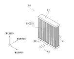
熱交換器10は、内部を流れる流体と外部を流れる空気との間で熱交換を行なうものである。具体的には、図1に概念を示すように、熱交換器10には、冷媒が流入出するための第1配管41及び第2配管42が取り付けられる。また、熱交換器10の近傍には、熱交換器10に風を送るためのファン6が配置される。ファン6は熱交換器10に向かう空気流を発生させ、その空気流が熱交換器10を通過する際に、熱交換器10と空気との間で熱交換が行なわれる。なお、熱交換器10は、空気から熱を奪う蒸発器としても、空気に熱を放出する凝縮器(放熱器)としても機能し、空気調和装置等に搭載できるものである。
熱交換器10は、内部を流れる流体と外部を流れる空気との間で熱交換を行なうものである。具体的には、図1に概念を示すように、熱交換器10には、冷媒が流入出するための第1配管41及び第2配管42が取り付けられる。また、熱交換器10の近傍には、熱交換器10に風を送るためのファン6が配置される。ファン6は熱交換器10に向かう空気流を発生させ、その空気流が熱交換器10を通過する際に、熱交換器10と空気との間で熱交換が行なわれる。なお、熱交換器10は、空気から熱を奪う蒸発器としても、空気に熱を放出する凝縮器(放熱器)としても機能し、空気調和装置等に搭載できるものである。
(2)熱交換器の詳細
(2-1)全体構成
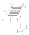
熱交換器10は、図2に示すように、伝熱ユニット群15、第1ヘッダ21及び第2ヘッダ22を有する。
(2-1)全体構成
熱交換器10は、図2に示すように、伝熱ユニット群15、第1ヘッダ21及び第2ヘッダ22を有する。
伝熱ユニット群15は、複数の伝熱ユニット30から構成される。また、伝熱ユニット群15は、ファン6により生じる空気流の方向が各伝熱ユニット30の間を通過するように配置される。各部材の配置についての詳細は後述する。
(2-2)ヘッダ
第1ヘッダ21は、図3に示すように、中空の部材で構成されており、ガス・液・気液二相の状態の冷媒が内部を流通可能に構成されている。そして、第1ヘッダ21は、伝熱ユニット30の上方で伝熱ユニット30に接続する。また、第1ヘッダ21の下面には、伝熱ユニット30と接続するための接続面21Sが形成される。接続面21Sには、後述する伝熱流路部31の端部31eが挿入される連結孔が形成される。なお、図3は第3方向D3から見たときの第1ヘッダ21の断面形状を示している。第3方向D3の定義については後述する。
第1ヘッダ21は、図3に示すように、中空の部材で構成されており、ガス・液・気液二相の状態の冷媒が内部を流通可能に構成されている。そして、第1ヘッダ21は、伝熱ユニット30の上方で伝熱ユニット30に接続する。また、第1ヘッダ21の下面には、伝熱ユニット30と接続するための接続面21Sが形成される。接続面21Sには、後述する伝熱流路部31の端部31eが挿入される連結孔が形成される。なお、図3は第3方向D3から見たときの第1ヘッダ21の断面形状を示している。第3方向D3の定義については後述する。
第2ヘッダ22は、伝熱ユニット30の下方で、第1配管41及び第2配管42と伝熱ユニット30とに接続し、第1配管41及び第2配管42と伝熱ユニット30との間の冷媒の流入出を可能にするものである。第2ヘッダ22は、第1ヘッダ21と同様に中空の部材で構成されており、ガス・液・気液二相の状態の冷媒が内部を流通可能に構成されている。ただし、第2ヘッダ22では、図4に示すように、第3方向D3に沿って内部を仕切る仕切り部材22pを有している。図4の例では、便宜上、第2ヘッダ22は仕切り部材22pにより、風上第2ヘッダ22U及び風下第2ヘッダ22Lに区切られるものとする。風上第2ヘッダ22U及び風下第2ヘッダ22Lは、それぞれ第2ヘッダ22及び第1ヘッダ21に接続する。なお、仕切り部材22pは第2ヘッダ22と一体的に形成されてもよいし、別個の物体により構成されてもよいものである。また、第2ヘッダ22の上面には、伝熱ユニット30と接続するための接続面22Sが形成される。接続面22Sには、後述する伝熱流路部31の端部31eが挿入される連結孔が形成される。なお、図4は第3方向D3から見たときの第2ヘッダ22の断面形状を示している。第3方向D3の定義については後述する。
(2-3)伝熱ユニット
(2-3-1)
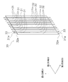
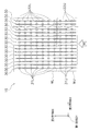
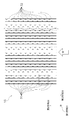
伝熱ユニット30は、図5に示すように、「第1方向D1」に延びる複数の伝熱流路部31及び複数の伝熱補助部32が、第1方向D1に対して傾斜又は直交する「第2方向D2」に並んで形成されるものである。ここでは、伝熱流路部31は略円筒形状であり、伝熱補助部32は略平板形状である。また、伝熱流路部31は、図6に示すように、第2方向D2に所定のピッチPPで並ぶように形成される。そして、このような伝熱ユニット30が、第1方向D1及び第2方向D2のいずれとも異なる「第3方向D3」に複数配置されることで、図7に示すような伝熱ユニット群15が形成される。ここでは、伝熱ユニット群15は、少なくとも3以上の伝熱ユニット30が積層状に配置される。
(2-3-1)
伝熱ユニット30は、図5に示すように、「第1方向D1」に延びる複数の伝熱流路部31及び複数の伝熱補助部32が、第1方向D1に対して傾斜又は直交する「第2方向D2」に並んで形成されるものである。ここでは、伝熱流路部31は略円筒形状であり、伝熱補助部32は略平板形状である。また、伝熱流路部31は、図6に示すように、第2方向D2に所定のピッチPPで並ぶように形成される。そして、このような伝熱ユニット30が、第1方向D1及び第2方向D2のいずれとも異なる「第3方向D3」に複数配置されることで、図7に示すような伝熱ユニット群15が形成される。ここでは、伝熱ユニット群15は、少なくとも3以上の伝熱ユニット30が積層状に配置される。
なお、説明の便宜上、第1方向D1、第2方向D2、第3方向D3は互いに直交するものとする。ただし、これらの方向D1~D3は完全に直交するものでなくても、互いに傾斜するものであれば、本実施形態に係る熱交換器10を実現することは可能である。
伝熱ユニット30は、第1ヘッダ21及び第2ヘッダ22の接続面21S,22Sで、第1ヘッダ21及び第2ヘッダ22に接続する。具体的には、伝熱ユニット30の第1方向D1の端部は、図5に示すように、伝熱流路部31の端部31eが伝熱補助部32の端部32eから突出している。伝熱流路部31の端部31eは、第1ヘッダ21及び第2ヘッダ22の接続面21S,22Sに設けられた連結孔に挿入される。そして、この接続箇所がロウ付け等されることで、伝熱ユニット30が第1ヘッダ21及び第2ヘッダ22の間に固定される(図8参照)。
伝熱流路部31は、第1ヘッダ21及び第2ヘッダ22の間の冷媒の移動を可能にするものである。具体的には、伝熱流路部31の内部には略円筒形状の通路が形成されており、この通路内を冷媒が移動する。なお、本実施形態に係る伝熱流路部31は第1方向D1に沿って直線状に形成される。
伝熱補助部32は、隣接する伝熱流路部31の内部を流れる冷媒と周囲の空気との間の熱交換を促進するものである。ここでは、伝熱補助部32は、伝熱流路部31と同様に第1方向D1に延びるように形成され、隣接する伝熱流路部31に接するように配置される。伝熱補助部32は、伝熱流路部31と一体的に形成されるものでもよいし、別個に形成されるものでもよい。
(2-3-2)
本実施形態に係る伝熱ユニット30には、少なくとも8以上の伝熱流路部31が形成される。そして、少なくとも2以上の伝熱流路部31が風上領域に配置される。
本実施形態に係る伝熱ユニット30には、少なくとも8以上の伝熱流路部31が形成される。そして、少なくとも2以上の伝熱流路部31が風上領域に配置される。
このような構成の一例として図8に示すようなものが挙げられる。ここでは、1つの伝熱ユニット30に、10本の伝熱流路部31が形成されている。また、第2ヘッダ22の内部は、仕切り部材22pにより、風上領域WUに配置される風上第2ヘッダ22Uと風下領域WLに配置される風下第2ヘッダ22Lとに区分けされている。そして、風上第2ヘッダ22Uに3本の伝熱流路部31Uが接続されており、風下第2ヘッダ22Lに7本の伝熱流路部31Lが接続されている。また、伝熱ユニット30の最風上側の端部には伝熱補助部32gが形成されている。なお、図8は熱交換器10を第3方向D3から見たときの断面形状を示す模式図である。
(2-4)冷媒流路
熱交換器10が蒸発器として用いられるときには、ファン6により生じた空気流Wが図9に示すように第2方向D2に沿って流れる。この状態で、熱交換器10に、第2配管42から液相の冷媒Fが流入する。続いて、冷媒Fは、第2配管42から風上第2ヘッダ22Uに流入する。そして、冷媒Fは、図10に示すように、風上第2ヘッダ22Uに接続された伝熱流路部31Uを経由して下方から上方に向けて流れる。次に、冷媒Fは、第1ヘッダ21及び風下第2ヘッダ22Lに接続された伝熱流路部31Lを経由して風下第2ヘッダ22Lに流入する。冷媒Fは、伝熱流路部31U,31Lを流れている間に空気流Wと熱交換を行う。これにより冷媒Fは蒸発して気相に変化する。そして、気相の冷媒Fが第1配管41から流出する。なお、図10では伝熱ユニット30を第3方向D3から見たときの状態を示している。
熱交換器10が蒸発器として用いられるときには、ファン6により生じた空気流Wが図9に示すように第2方向D2に沿って流れる。この状態で、熱交換器10に、第2配管42から液相の冷媒Fが流入する。続いて、冷媒Fは、第2配管42から風上第2ヘッダ22Uに流入する。そして、冷媒Fは、図10に示すように、風上第2ヘッダ22Uに接続された伝熱流路部31Uを経由して下方から上方に向けて流れる。次に、冷媒Fは、第1ヘッダ21及び風下第2ヘッダ22Lに接続された伝熱流路部31Lを経由して風下第2ヘッダ22Lに流入する。冷媒Fは、伝熱流路部31U,31Lを流れている間に空気流Wと熱交換を行う。これにより冷媒Fは蒸発して気相に変化する。そして、気相の冷媒Fが第1配管41から流出する。なお、図10では伝熱ユニット30を第3方向D3から見たときの状態を示している。
熱交換器10が凝縮器として用いられるときには、蒸発器のときとは逆向きに冷媒Fが流れる。すなわち、第1配管41から気相の冷媒Fが流入し、第2配管42から液相の冷媒Fが流出する。
(3)熱交換器10の製造方法
伝熱ユニット30は、例えばアルミニウムまたはアルミニウム合金などの金属材料から製造される。具体的には、まず、図5の断面形状に相当する型を用いて金属材料の押出成形が行なわれ、伝熱流路部31及び伝熱補助部32が一体的に形成される。続いて、伝熱補助部32の一部を切除して切欠部33が設けられる。切欠部33は、例えば、伝熱補助部32の複数箇所を打ち抜きによって切除して形成される。
伝熱ユニット30は、例えばアルミニウムまたはアルミニウム合金などの金属材料から製造される。具体的には、まず、図5の断面形状に相当する型を用いて金属材料の押出成形が行なわれ、伝熱流路部31及び伝熱補助部32が一体的に形成される。続いて、伝熱補助部32の一部を切除して切欠部33が設けられる。切欠部33は、例えば、伝熱補助部32の複数箇所を打ち抜きによって切除して形成される。
第1ヘッダ21及び第2ヘッダ22は、金属材料を管状に加工することによって製造される。第1ヘッダ21及び第2ヘッダ22には、伝熱流路部31の端部31eを挿入するための連結孔が設けられる。連結孔は、例えばドリルによって形成される円形の貫通孔である。
熱交換器10の組み立ては、第1ヘッダ21及び第2ヘッダ22の連結孔に、伝熱ユニット30の伝熱流路部31の端部31eが挿入される。これにより、伝熱補助部32の端部32eが第1ヘッダ21及び第2ヘッダ22の接続面21S,22Sに接触する状態になる。この接触箇所において、伝熱ユニット30と第1ヘッダ21及び第2ヘッダ22がロウ付け等されて固定される。
(4)特徴
(4-1)
以上説明したように、本実施形態に係る熱交換器10は、第1方向D1に延びる複数の伝熱流路部31及び複数の伝熱補助部32が第1方向D1に対して傾斜又は直交する第2方向D2に並んで形成される伝熱ユニット30を有する。ここで、伝熱ユニット30は、第1方向D1及び第2方向D2のいずれとも異なる第3方向D3に複数配置され、伝熱ユニット群15を形成する。
(4-1)
以上説明したように、本実施形態に係る熱交換器10は、第1方向D1に延びる複数の伝熱流路部31及び複数の伝熱補助部32が第1方向D1に対して傾斜又は直交する第2方向D2に並んで形成される伝熱ユニット30を有する。ここで、伝熱ユニット30は、第1方向D1及び第2方向D2のいずれとも異なる第3方向D3に複数配置され、伝熱ユニット群15を形成する。
また、本実施形態に係る熱交換器10では、伝熱ユニット30が、第2方向D2に沿って風上領域WU及び風下領域WLに区切られる。そして、熱交換器10は、蒸発器として用いられるときに、風上領域WUに配置された伝熱流路部31Uに冷媒Fを流入させてから、風下領域WLに配置された伝熱流路部31Lに冷媒Fを流出させる。
要するに、本実施形態に係る熱交換器10では、空気流Wが生じる第2方向D2に少なくとも1回は冷媒流路が折り返される。これにより、熱交換性能の優れた熱交換器を提供できる。
補足すると、例えば図11に示すように、伝熱ユニット30Zに、第1方向D1に沿って下方から上方に1回だけ冷媒Fを流す形態の熱交換器10Zでは、低い温度(例えば摂氏7度以下)の環境下で蒸発器として使用した場合、風上側の伝熱流路部における伝熱量が大きいため、伝熱ユニット30Zの間に着霜が生じることがある。さらに、着霜に起因して風路閉塞が生じることがある。なお、図11に示す第1ヘッダ21Z及び第2ヘッダ22Zの内部には仕切り部材等は設けられていない。
これに対し、本実施形態に係る熱交換器10の構成では、第2配管42から流入する冷媒Fの流路の数を風上伝熱流路部31Uの数に制限することで、冷媒の圧力損失が生じる。そして、この圧力損失に起因して、風上伝熱流路部31Uにおける冷媒温度が高くなる。そのため、熱交換器10を蒸発器として用いたときに、風上伝熱流路部31Uでの熱交換量が抑制される。これにより、伝熱ユニット群15内での位置に応じた熱流束の変動を抑えることができる。結果として、熱交換器10を低い温度環境(例えば摂氏7度以下)で蒸発器として用いたときに、局所的に着霜が生じることを回避することができ、熱交換性能の優れた熱交換器を提供することができる。
また、図11に示すような形態の熱交換器10Zでは、最風上側の伝熱補助部の前縁効果により、風上側の伝熱流路部の熱交換量が、風下側の伝熱流路部の熱交換量に比較して多くなる。そのため、第2配管42から流入する冷媒Fを、複数の伝熱流路部に流した場合、風上側の伝熱流路部において冷媒Fが蒸発しきってしまうことがある。結果として、熱交換器10Zにおいて十分な熱交換が行なわれない事態が生じ得る。
これに対し、本実施形態に係る熱交換器10の構成では、第2配管42から流入する冷媒Fの全てを一旦、風上側の伝熱流路部31Uに流すので、風上側の伝熱流路部31Uで冷媒が蒸発しきってしまう事態を回避できる。結果として、熱交換器10の熱交換性能を最適化できる。
(4-2)
また、本実施形態に係る熱交換器10は、風上領域WUに配置される伝熱流路部31Uの数よりも風下領域WLに配置される伝熱流路部31Lの数の方が多いものである。また、各伝熱ユニット30が、少なくとも8以上の伝熱流路部31を有し、少なくとも2以上の伝熱流路部31Uが風上領域WUに配置されるものである。このような構成により、熱交換器10を低い温度環境(例えば摂氏7度以下)で蒸発器として用いたときに、着霜の発生を抑えつつ、最適な熱交換を実現できる。
また、本実施形態に係る熱交換器10は、風上領域WUに配置される伝熱流路部31Uの数よりも風下領域WLに配置される伝熱流路部31Lの数の方が多いものである。また、各伝熱ユニット30が、少なくとも8以上の伝熱流路部31を有し、少なくとも2以上の伝熱流路部31Uが風上領域WUに配置されるものである。このような構成により、熱交換器10を低い温度環境(例えば摂氏7度以下)で蒸発器として用いたときに、着霜の発生を抑えつつ、最適な熱交換を実現できる。
(4-3)
また、本実施形態に係る熱交換器10は、第1方向D1に沿って上下から伝熱ユニット30に接続し、冷媒流路の一部を形成する第1ヘッダ21(上側ヘッダ)及び第2ヘッダ22(下側ヘッダ)をさらに備える。このような構成により、伝熱ユニット30の長手方向を鉛直方向に向けることができ、付着した水(結露水等)を容易に排出できる。また、組立性・加工性を高めることもできる。
また、本実施形態に係る熱交換器10は、第1方向D1に沿って上下から伝熱ユニット30に接続し、冷媒流路の一部を形成する第1ヘッダ21(上側ヘッダ)及び第2ヘッダ22(下側ヘッダ)をさらに備える。このような構成により、伝熱ユニット30の長手方向を鉛直方向に向けることができ、付着した水(結露水等)を容易に排出できる。また、組立性・加工性を高めることもできる。
ただし、本実施形態に係る熱交換器10は、第1ヘッダ21及び第2ヘッダ22を上下方向に代えて左右方向に設ける構成を排除するものではない。
(4-4)
また、本実施形態に係る熱交換器10は、風上領域WU及び風下領域WLが、第2ヘッダ22(下側ヘッダ)の内部に配置される仕切り部材22pにより形成される。よって、伝熱ユニット30に特殊な加工等をせずに、風上領域WU及び風下領域WLを容易に形成することができる。
また、本実施形態に係る熱交換器10は、風上領域WU及び風下領域WLが、第2ヘッダ22(下側ヘッダ)の内部に配置される仕切り部材22pにより形成される。よって、伝熱ユニット30に特殊な加工等をせずに、風上領域WU及び風下領域WLを容易に形成することができる。
なお、本実施形態に係る熱交換器10は、冷媒の流通経路に応じて、第2ヘッダ22に代えて第1ヘッダ21の内部に仕切り部材を設けてもよい。若しくは、冷媒の流通経路に応じて、第1ヘッダ21及び第2ヘッダ22のいずれにも仕切り部材を設けてもよい。
(4-5)
また、本実施形態に係る熱交換器10は、各伝熱ユニット30を、金属材料の押出成形によって単一の部材から形成することができる。また、打ち抜きにより複数の切欠部33を一度に形成することができる。したがって、組立性・加工性の高い熱交換器10を提供できる。
また、本実施形態に係る熱交換器10は、各伝熱ユニット30を、金属材料の押出成形によって単一の部材から形成することができる。また、打ち抜きにより複数の切欠部33を一度に形成することができる。したがって、組立性・加工性の高い熱交換器10を提供できる。
(5)変形例
(5-1)変形例A
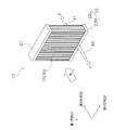
本実施形態に係る熱交換器10は、冷媒を減圧させる減圧機構をさらに備えるものでもよい。具体的には、熱交換器10は、図12に概念を示すように、風上領域WUの冷媒流路(伝熱流路部31U)と風下領域WLの冷媒流路(伝熱流路部31L)との間に電動弁などにより構成される減圧機構25を備えるものでもよい。減圧機構25により冷媒Fを膨張させることで、風上領域の冷媒温度を最適化することができる。結果として、熱交換器10を低い温度環境(例えば摂氏7度以下)で蒸発器として用いたときに、着霜の発生をさらに抑制することができる。
(5-1)変形例A
本実施形態に係る熱交換器10は、冷媒を減圧させる減圧機構をさらに備えるものでもよい。具体的には、熱交換器10は、図12に概念を示すように、風上領域WUの冷媒流路(伝熱流路部31U)と風下領域WLの冷媒流路(伝熱流路部31L)との間に電動弁などにより構成される減圧機構25を備えるものでもよい。減圧機構25により冷媒Fを膨張させることで、風上領域の冷媒温度を最適化することができる。結果として、熱交換器10を低い温度環境(例えば摂氏7度以下)で蒸発器として用いたときに、着霜の発生をさらに抑制することができる。
(5-2)変形例B
本実施形態に係る熱交換器10は、上記構成に限られるものではない。すなわち、本実施形態に係る熱交換器10は、空気流Wが生じる第2方向D2に少なくとも1回は冷媒流路が折り返されものであれば、任意の形態を採用することができる。例えば、図13に示すような冷媒流路を有する構成の熱交換器10Yであってもよい。なお、図13は熱交換器10Yの内部に形成される冷媒流路を説明するための模式図である。
本実施形態に係る熱交換器10は、上記構成に限られるものではない。すなわち、本実施形態に係る熱交換器10は、空気流Wが生じる第2方向D2に少なくとも1回は冷媒流路が折り返されものであれば、任意の形態を採用することができる。例えば、図13に示すような冷媒流路を有する構成の熱交換器10Yであってもよい。なお、図13は熱交換器10Yの内部に形成される冷媒流路を説明するための模式図である。
図13に示す例では、風上第2ヘッダ22Uの中央部付近で、風上第2ヘッダ22Uの内部に第2方向D2に沿って仕切り部材22psが設けられている。これにより、風上第2ヘッダ22Uが、風上上流第2ヘッダ22UAと風上下流第2ヘッダ22UBとの2つの領域に分けられる。また、図13に示す例では、第1ヘッダ21の内部にも仕切り部材21p等が設けられており、第1ヘッダ21が、第2方向D2に沿って風上第1ヘッダ21Uと風下第1ヘッダ21Lとに分けられている。そして、このような構成の熱交換器10Yでは、第2配管42から風上上流第2ヘッダ22UAに流入した冷媒Fが、風上上流領域の伝熱流路部を通って、風上第1ヘッダ21Uに流入する。続いて、冷媒Fは、風上第1ヘッダ21Uを経由して風上下流領域の伝熱流路部に流入する。そして、風上下流第2ヘッダ22UBに流入した冷媒が、図示しない連絡配管等を介して、風下第2ヘッダ22Lに流入する。風下第2ヘッダ22Lに流入した冷媒Fは、風下第1ヘッダ21Lを経由して第1配管41に流出される。なお、熱交換器10Yでは、第1配管41が風下第1ヘッダ21Lに接続されている。
このような形態の熱交換器10Yであっても、空気流Wが生じる第2方向D2に少なくとも1回は冷媒流路が折り返されているので、既述したのと同様の効果が実現される。
(5-3)変形例C
また、本実施形態に係る熱交換器10は、第1方向D1からみたときに、伝熱ユニット30の第2方向D2の風上側の端部(ここでは伝熱補助部32g)に断熱材Iが塗布されるものであってもよい(図14,15参照)。これにより、当該端部における温度の低下を抑えることができる。結果として、熱交換器10を低い温度環境(例えば摂氏7度以下)で蒸発器として用いたときに、着霜を抑制でき、風路閉塞を回避又は遅らせることができる。
また、本実施形態に係る熱交換器10は、第1方向D1からみたときに、伝熱ユニット30の第2方向D2の風上側の端部(ここでは伝熱補助部32g)に断熱材Iが塗布されるものであってもよい(図14,15参照)。これにより、当該端部における温度の低下を抑えることができる。結果として、熱交換器10を低い温度環境(例えば摂氏7度以下)で蒸発器として用いたときに、着霜を抑制でき、風路閉塞を回避又は遅らせることができる。
なお、図14,15に示す例では、伝熱ユニット30の上記端部が伝熱補助部32gである。さらに、この最風上側の伝熱補助部32g(第1伝熱補助部)は閉塞された形状である。ここで、「閉塞された形状」とは、穴や切込み等がなくフラットな形状のことをいう。これにより、除霜運転時の排水性をさらに高めることができる。
補足すると、伝熱補助部32gに穴や切り込み等が形成されていると、その穴や切り込み等に、霜が解けて生じた水が保水されることがある。そして、その場合には、保水した箇所が次の着霜の起点となることがある。これに対し、変形例Cに係る熱交換器10では、伝熱補助部32gが穴や切込み等がない形状であるので、除霜運転後に生じる着霜を抑制できる。
(5-4)変形例D
また、本実施形態に係る伝熱流路部31は、上述したものに限られず、他の形態であってもよい。例えば、伝熱流路部31を第1方向D1からみたときの断面形状が、半円形状、楕円形状、扁平形状、翼型の上半分形状、及び/又は翼型の下半分形状のいずれか一つ又は任意の組み合わせであってもよい。要するに、熱交換器10は、熱交換性能を最適化する形状を採用することができる。
また、本実施形態に係る伝熱流路部31は、上述したものに限られず、他の形態であってもよい。例えば、伝熱流路部31を第1方向D1からみたときの断面形状が、半円形状、楕円形状、扁平形状、翼型の上半分形状、及び/又は翼型の下半分形状のいずれか一つ又は任意の組み合わせであってもよい。要するに、熱交換器10は、熱交換性能を最適化する形状を採用することができる。
(5-5)変形例E
また、本実施形態に係る伝熱ユニット群15は、図16,17に示すような形態のものでもよい。なお、図17は図16の一部拡大図である(図16の点線部に相当)。
また、本実施形態に係る伝熱ユニット群15は、図16,17に示すような形態のものでもよい。なお、図17は図16の一部拡大図である(図16の点線部に相当)。
図16,17に示す例では、伝熱ユニット30(30a,30b,30cを含む)は、第2方向D2における第1位置L1(L1a,L1b,L1cを含む)で膨出して伝熱流路部31を形成する第1膨出部31p(31pa,31pb,31pcを含む)と、第1膨出部31pが形成される向きとは反対向きで第1位置L1に形成される第1平面部31q(31qa,31qb,31qcを含む)とを有する。なお、変形例Eでは、「第1位置」は伝熱ユニット毎に定義されており、伝熱ユニット30aの第1位置L1aと、伝熱ユニット30b,30cの第1位置L1b,L1cとは異なる位置を意味する。
また、少なくとも一の伝熱ユニット30aが、一方の側で隣接する伝熱ユニット30bとは、第1膨出部31paが形成される面と、隣接する伝熱ユニット30bの第1膨出部31pbが形成される面とが対向する向きに配置される。また、その伝熱ユニット30aは、他方の側で隣接する他の伝熱ユニット30cとは、第1平面部31qaが形成される面と、他の伝熱ユニット30cの第1平面部31qcが形成される面とが対向する向きに配置される。
このような構成により、熱交換器10が蒸発器として用いられた場合、第1平面部31qa,31qc同士等が対向する風路において、空気流が素通りするので、着霜の発生量を抑制することができる。これにより、使用環境によっては熱交換性能を高めることができる。
なお、第1膨出部31pa,31pb同士が対向する風路では、空気流の縮流が発生し、その風路に着霜が集中的に発生し易くなる。しかし、そのような着霜が生じた場合であったとしても、使用環境によっては、図7に示すような略同一の膨出部が伝熱ユニットの両面に形成される熱交換器に比して、熱交換器全体における熱交換性能を高めることができる。
また、変形例Eに係る熱交換器10は、図17に示すように、第1方向D1からみたときに、隣接する伝熱ユニット30a,30bにおける第1位置L1a,L1bが重複しないように配置されている。換言すると、隣接する伝熱ユニット30a,30b間の風路で、第1膨出部31pa,30pbが千鳥状に配置されている。そのため、図7に示すように膨出部同士が近接する構成に比して、隣接する伝熱ユニット31a,31b間の風路の流路断面積を増加させることができる。したがって、熱交換器10を低い温度環境(例えば摂氏7度以下)で蒸発器として用いたときに、着霜による風路閉塞をさらに抑制することができる。
さらに、伝熱ユニット30は、第1平面部31qに代えて、第1膨出部31pより小さく膨出する第2膨出部を有するものでもよい。この場合でも、上記と同様の議論が成立する。
(5-6)変形例F
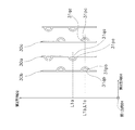
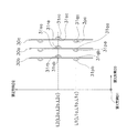
また、本実施形態に係る伝熱ユニット群15は、図18,19に示すような形態のものでもよい。なお、図19は図18の一部拡大図である(図18の点線部に相当)。
また、本実施形態に係る伝熱ユニット群15は、図18,19に示すような形態のものでもよい。なお、図19は図18の一部拡大図である(図18の点線部に相当)。
図18,19に示す例では、伝熱ユニット30(30a,30b,30cを含む)は、第2方向D2における第1位置L1(L1a,L1b,L1cを含む)で膨出して伝熱流路部31を形成する第1膨出部31p(31pa,31pb,31pcを含む)と、第1膨出部31pが形成される向きとは反対向きで第1位置L1に形成される第1平面部31q(31qa,31qb,31qc)と、第1膨出部31pが形成される向きとは反対向きで、第2方向D2における第2位置L2(L2a,L2b,L2cを含む)で膨出して伝熱流路部31を形成する第3膨出部31r(31ra,31rb,31rcを含む)と、第3膨出部31rが形成される向きとは反対向きで第2位置L2に形成される第2平面部31s(31sa,31sb,31scを含む)とを有する。ここでは、第1膨出部31pと第3膨出部31rとは同一形状である。また、第1膨出部31pと第3膨出部31rとは第2方向D2で隣接する。
また、少なくとも一の伝熱ユニット30aが、一方の側で隣接する伝熱ユニット30bとは、第1膨出部31paが形成される面と、隣接する伝熱ユニット30bの第1平面部31qbが形成される面とが対向する向きに配置される。また、その伝熱ユニット30aは、他方の側で隣接する他の伝熱ユニット30cとは、第3膨出部31raが形成される面と、他の隣接する伝熱ユニット30cの第2平面部30scが形成される面とが対向する向きに配置される。
また、隣接する伝熱ユニット30a,30b(又は30a,30c)における第1位置L1a,L1b(又はL1a,L1c)同士が第1方向D1から見たときに重複するように配置される。また、第2位置同士L2a,L2b(又はL2a,L2c)も第1方向D1から見たときに重複するように配置される。補足すると、「第1位置L1」「第2位置L2」は伝熱ユニット毎に定義されるものであるが、ここでは、各伝熱ユニット30a,30b,30cにおいて同じ位置になるようにしている。
要するに、変形例Fに係る熱交換器10は、隣接する伝熱ユニット30a,30bの間で第1膨出部31pa,31pb同士等が対向せずに、反対向きに形成される。そのため、第1膨出部31pa,31pb同士等が対向する構成に比して、縮流の発生を抑えることができる。結果して、通風抵抗の増大を抑制することができ、最適な熱交換性能を実現することが可能となる。また、上記構成の熱交換器10であれば、(例えば摂氏7度以下)蒸発器として用いたときに、図7に示すような略同一の膨出部が伝熱ユニットの両面に形成される熱交換器に比して局所的な着霜を抑制することができる。
なお、伝熱ユニット30は、第1平面部31qに代えて第1膨出部31pより小さく膨出する第2膨出部を有し、第2平面部31sに代えて第3膨出部31rより小さく膨出する第4膨出部を有するものでもよい。この場合でも、上記と同様の議論が成立する。
(5-7)変形例G
また、本実施形態に係る熱交換器10は、図20に示すように、第1方向D1からみたときに、伝熱ユニット30における第2方向D2の端部に、他の伝熱補助部32よりも長い伝熱補助部32g(第1伝熱補助部)が形成されるものでもよい。このような熱交換器10では、最風上側の伝熱流路部31gと隣接する伝熱補助部32gとの間の距離が長いので、最風上側の伝熱流路部31gから伝熱補助部32gへの伝熱量を下げることができる。これにより、伝熱ユニット30表面上の熱流束分布を均一化することができる。結果として、熱交換器10を低い温度環境(例えば摂氏7度以下)で蒸発器として用いたときに、風路の入口部に着霜が局所的に発生するのを抑制又は回避することができる。
また、本実施形態に係る熱交換器10は、図20に示すように、第1方向D1からみたときに、伝熱ユニット30における第2方向D2の端部に、他の伝熱補助部32よりも長い伝熱補助部32g(第1伝熱補助部)が形成されるものでもよい。このような熱交換器10では、最風上側の伝熱流路部31gと隣接する伝熱補助部32gとの間の距離が長いので、最風上側の伝熱流路部31gから伝熱補助部32gへの伝熱量を下げることができる。これにより、伝熱ユニット30表面上の熱流束分布を均一化することができる。結果として、熱交換器10を低い温度環境(例えば摂氏7度以下)で蒸発器として用いたときに、風路の入口部に着霜が局所的に発生するのを抑制又は回避することができる。
さらに、本実施形態に係る熱交換器10は、図21に示すように、隣接する伝熱ユニット30において、伝熱補助部32gの第2方向D2における長さを異なるようにして、端部を千鳥状に配置するものでもよい。このような熱交換器では、風路の入口部に断面積の広い部分が形成される。したがって、熱交換器10を低い温度環境(例えば摂氏7度以下)で蒸発器として用いたときに、風路の入口部における着霜を抑制又は回避することができる。
(5-8)変形例H
また、本実施形態に係る熱交換器10は、図22に示すように、第1方向D1からみたときに、伝熱ユニット30が直線状だけでなく波形状に加工されるものでもよい。伝熱ユニット30が直線状の場合は風路抵抗を抑えることができる。一方、伝熱ユニット30が波形状の場合は空気流と冷媒との熱交換量を増やすことができる。要するに、使用環境に応じて、熱交換性能が最適な熱交換器を提供できる。
また、本実施形態に係る熱交換器10は、図22に示すように、第1方向D1からみたときに、伝熱ユニット30が直線状だけでなく波形状に加工されるものでもよい。伝熱ユニット30が直線状の場合は風路抵抗を抑えることができる。一方、伝熱ユニット30が波形状の場合は空気流と冷媒との熱交換量を増やすことができる。要するに、使用環境に応じて、熱交換性能が最適な熱交換器を提供できる。
(5-9)変形例I
本実施形態に係る熱交換器10は、伝熱管とフィンとが一方向に並ぶベッセル型熱交換器(細径多管式熱交換器)への適用が可能であるが、これに限られるものではない。例えば、マイクロチャネル型熱交換器(扁平多穴管式熱交換器)への適用も可能である。
本実施形態に係る熱交換器10は、伝熱管とフィンとが一方向に並ぶベッセル型熱交換器(細径多管式熱交換器)への適用が可能であるが、これに限られるものではない。例えば、マイクロチャネル型熱交換器(扁平多穴管式熱交換器)への適用も可能である。
<他の実施形態>
以上、実施形態を説明したが、請求の範囲の趣旨及び範囲から逸脱することなく、形態や詳細の多様な変更が可能なことが理解されるであろう。
以上、実施形態を説明したが、請求の範囲の趣旨及び範囲から逸脱することなく、形態や詳細の多様な変更が可能なことが理解されるであろう。
すなわち、本開示は、上記各実施形態そのままに限定されるものではない。本開示は、実施段階ではその要旨を逸脱しない範囲で構成要素を変形して具体化できるものである。また、本開示は、上記各実施形態に開示されている複数の構成要素の適宜な組み合わせにより種々の開示を形成できるものである。例えば、実施形態に示される全構成要素から幾つかの構成要素は削除してもよいものである。さらに、異なる実施形態に構成要素を適宜組み合わせてもよいものである。
10 熱交換器
21 第1ヘッダ(上側ヘッダ)
21p 仕切り部材
22 第2ヘッダ(下側ヘッダ)
22p 仕切り部材
22ps 仕切り部材
25 減圧機構
30 伝熱ユニット
30a 伝熱ユニット(一の伝熱ユニット)
30b 伝熱ユニット(一方の側で隣接する伝熱ユニット)
30c 伝熱ユニット(他方の側で隣接する伝熱ユニット)
31 伝熱流路部
31p 第1膨出部
31q 第1平面部
31r 第3膨出部
31s 第2平面部
31L 風下伝熱流路部
31U 風上伝熱流路部
32 伝熱補助部
32g 第2方向端部の伝熱補助部(第1伝熱補助部)
D1 第1方向
D2 第2方向
D3 第3方向
I 断熱材
L1 第1位置
L2 第2位置
WL 風下領域
WU 風上領域
21 第1ヘッダ(上側ヘッダ)
21p 仕切り部材
22 第2ヘッダ(下側ヘッダ)
22p 仕切り部材
22ps 仕切り部材
25 減圧機構
30 伝熱ユニット
30a 伝熱ユニット(一の伝熱ユニット)
30b 伝熱ユニット(一方の側で隣接する伝熱ユニット)
30c 伝熱ユニット(他方の側で隣接する伝熱ユニット)
31 伝熱流路部
31p 第1膨出部
31q 第1平面部
31r 第3膨出部
31s 第2平面部
31L 風下伝熱流路部
31U 風上伝熱流路部
32 伝熱補助部
32g 第2方向端部の伝熱補助部(第1伝熱補助部)
D1 第1方向
D2 第2方向
D3 第3方向
I 断熱材
L1 第1位置
L2 第2位置
WL 風下領域
WU 風上領域
Claims (9)
- 第1方向(D1)に延びる複数の伝熱流路部(31)及び複数の伝熱補助部(32)が前記第1方向に対して傾斜又は直交する第2方向(D2)に並んで形成される伝熱ユニット(30)を有し、前記伝熱ユニットが前記第1方向及び前記第2方向のいずれとも異なる第3方向(D3)に複数配置される熱交換器(10)であって、
前記伝熱ユニットは、前記第2方向に沿って風上領域(WU)及び風下領域(WL)に区切られるものであり、
蒸発器として用いるときに、前記風上領域に配置された伝熱流路部(31U)に冷媒を流入させてから、前記風下領域に配置された伝熱流路部(31L)に前記冷媒を流出させる、熱交換器。 - 前記風上領域に配置される伝熱流路部の数よりも前記風下領域に配置される伝熱流路部の数の方が多い、
請求項1に記載の熱交換器。 - 前記冷媒を減圧させる減圧機構(25)をさらに備え、
前記風上領域に配置される伝熱流路部から前記風下領域に配置される伝熱流路部に前記減圧機構を経由して冷媒を流入させる、
請求項1または2に記載の熱交換器。 - 前記伝熱ユニットに、前記第1方向に沿って上下から接続し、前記冷媒の流路の一部を形成する上側ヘッダ(21)及び下側ヘッダ(22)をさらに備える、
請求項1から3のいずれか1項に記載の熱交換器。 - 前記風上領域及び前記風下領域は、前記上側ヘッダ及び/又は前記下側ヘッダの内部に配置される仕切り部材(21p,22p)により形成される、
請求項4に記載の熱交換器。 - 各伝熱ユニットは、少なくとも8以上の伝熱流路部を有し、少なくとも2以上の伝熱流路部が前記風上領域に配置される、
請求項1から5のいずれか1項に記載の熱交換器。 - 前記第1方向視で、前記伝熱ユニットの前記第2方向の端部に断熱材(I)が塗布されている、
請求項1から6のいずれか1項に記載の熱交換器。 - 前記伝熱ユニットには、前記第1方向視で前記第2方向の端部に前記伝熱補助部の一つである第1伝熱補助部(32g)が形成されており、
前記第1伝熱補助部は閉塞された形状である、
請求項7に記載の熱交換器。 - 請求項1から8のいずれか1項に記載の熱交換器が搭載された空気調和装置。
Priority Applications (3)
| Application Number | Priority Date | Filing Date | Title |
|---|---|---|---|
| CN201980016308.6A CN111801541A (zh) | 2018-03-01 | 2019-02-22 | 热交换器 |
| US16/977,284 US20210003350A1 (en) | 2018-03-01 | 2019-02-22 | Heat exchanger |
| EP19761287.2A EP3760957B1 (en) | 2018-03-01 | 2019-02-22 | Air conditioner |
Applications Claiming Priority (2)
| Application Number | Priority Date | Filing Date | Title |
|---|---|---|---|
| JP2018036981A JP7406297B2 (ja) | 2018-03-01 | 2018-03-01 | 熱交換器 |
| JP2018-036981 | 2018-03-01 |
Publications (1)
| Publication Number | Publication Date |
|---|---|
| WO2019167839A1 true WO2019167839A1 (ja) | 2019-09-06 |
Family
ID=67808845
Family Applications (1)
| Application Number | Title | Priority Date | Filing Date |
|---|---|---|---|
| PCT/JP2019/006840 Ceased WO2019167839A1 (ja) | 2018-03-01 | 2019-02-22 | 熱交換器 |
Country Status (5)
| Country | Link |
|---|---|
| US (1) | US20210003350A1 (ja) |
| EP (1) | EP3760957B1 (ja) |
| JP (1) | JP7406297B2 (ja) |
| CN (1) | CN111801541A (ja) |
| WO (1) | WO2019167839A1 (ja) |
Families Citing this family (1)
| Publication number | Priority date | Publication date | Assignee | Title |
|---|---|---|---|---|
| US12601547B2 (en) | 2023-05-10 | 2026-04-14 | Rtx Corporation | Extruded connected microtube and heat exchanger |
Citations (11)
| Publication number | Priority date | Publication date | Assignee | Title |
|---|---|---|---|---|
| JPS59153493U (ja) * | 1983-03-31 | 1984-10-15 | 三菱重工業株式会社 | 熱交換器 |
| JPH06117790A (ja) * | 1992-10-06 | 1994-04-28 | Sanden Corp | 熱交換器 |
| JPH09159386A (ja) * | 1995-12-13 | 1997-06-20 | Sanden Corp | 多管式熱交換器 |
| JPH10300275A (ja) * | 1997-04-25 | 1998-11-13 | Daikin Ind Ltd | 空調室外機 |
| JP2001091101A (ja) * | 1999-09-20 | 2001-04-06 | Fujitsu General Ltd | 空気調和機の熱交換器 |
| JP2006090636A (ja) | 2004-09-24 | 2006-04-06 | Daikin Ind Ltd | 細径多管式熱交換器の細径伝熱管ユニット |
| JP2010117091A (ja) * | 2008-11-13 | 2010-05-27 | Denso Corp | 熱交換器 |
| JP2011122778A (ja) * | 2009-12-11 | 2011-06-23 | Toshiba Carrier Corp | 熱交換器、冷凍サイクル装置 |
| JP2014137172A (ja) * | 2013-01-16 | 2014-07-28 | Daikin Ind Ltd | 熱交換器及び冷凍装置 |
| WO2016013100A1 (ja) * | 2014-07-25 | 2016-01-28 | 三菱電機株式会社 | 熱交換器およびこの熱交換器を備えた空調冷凍装置 |
| WO2017221400A1 (ja) * | 2016-06-24 | 2017-12-28 | 三菱電機株式会社 | 冷凍サイクル装置およびそれに用いられる室外熱交換器 |
Family Cites Families (6)
| Publication number | Priority date | Publication date | Assignee | Title |
|---|---|---|---|---|
| JPH07305986A (ja) * | 1994-05-16 | 1995-11-21 | Sanden Corp | 多管式熱交換器 |
| JP2006322698A (ja) * | 2005-04-22 | 2006-11-30 | Denso Corp | 熱交換器 |
| JP5920178B2 (ja) | 2011-12-05 | 2016-05-18 | 株式会社デンソー | ヒートポンプサイクル |
| JP2014137177A (ja) | 2013-01-16 | 2014-07-28 | Daikin Ind Ltd | 熱交換器および冷凍装置 |
| JP6387858B2 (ja) | 2015-02-26 | 2018-09-12 | 株式会社デンソー | 冷媒熱交換器 |
| CN205505498U (zh) * | 2015-09-15 | 2016-08-24 | 北京旭日双圆制冷设备有限公司 | 高效节能多通道温度交换器 |
-
2018
- 2018-03-01 JP JP2018036981A patent/JP7406297B2/ja active Active
-
2019
- 2019-02-22 WO PCT/JP2019/006840 patent/WO2019167839A1/ja not_active Ceased
- 2019-02-22 CN CN201980016308.6A patent/CN111801541A/zh active Pending
- 2019-02-22 EP EP19761287.2A patent/EP3760957B1/en active Active
- 2019-02-22 US US16/977,284 patent/US20210003350A1/en not_active Abandoned
Patent Citations (11)
| Publication number | Priority date | Publication date | Assignee | Title |
|---|---|---|---|---|
| JPS59153493U (ja) * | 1983-03-31 | 1984-10-15 | 三菱重工業株式会社 | 熱交換器 |
| JPH06117790A (ja) * | 1992-10-06 | 1994-04-28 | Sanden Corp | 熱交換器 |
| JPH09159386A (ja) * | 1995-12-13 | 1997-06-20 | Sanden Corp | 多管式熱交換器 |
| JPH10300275A (ja) * | 1997-04-25 | 1998-11-13 | Daikin Ind Ltd | 空調室外機 |
| JP2001091101A (ja) * | 1999-09-20 | 2001-04-06 | Fujitsu General Ltd | 空気調和機の熱交換器 |
| JP2006090636A (ja) | 2004-09-24 | 2006-04-06 | Daikin Ind Ltd | 細径多管式熱交換器の細径伝熱管ユニット |
| JP2010117091A (ja) * | 2008-11-13 | 2010-05-27 | Denso Corp | 熱交換器 |
| JP2011122778A (ja) * | 2009-12-11 | 2011-06-23 | Toshiba Carrier Corp | 熱交換器、冷凍サイクル装置 |
| JP2014137172A (ja) * | 2013-01-16 | 2014-07-28 | Daikin Ind Ltd | 熱交換器及び冷凍装置 |
| WO2016013100A1 (ja) * | 2014-07-25 | 2016-01-28 | 三菱電機株式会社 | 熱交換器およびこの熱交換器を備えた空調冷凍装置 |
| WO2017221400A1 (ja) * | 2016-06-24 | 2017-12-28 | 三菱電機株式会社 | 冷凍サイクル装置およびそれに用いられる室外熱交換器 |
Non-Patent Citations (1)
| Title |
|---|
| See also references of EP3760957A4 |
Also Published As
| Publication number | Publication date |
|---|---|
| EP3760957A1 (en) | 2021-01-06 |
| CN111801541A (zh) | 2020-10-20 |
| JP7406297B2 (ja) | 2023-12-27 |
| EP3760957B1 (en) | 2022-11-30 |
| JP2019152362A (ja) | 2019-09-12 |
| US20210003350A1 (en) | 2021-01-07 |
| EP3760957A4 (en) | 2021-04-21 |
Similar Documents
| Publication | Publication Date | Title |
|---|---|---|
| WO2013161802A1 (ja) | 熱交換器、及び空気調和機 | |
| JP2007278556A (ja) | 熱交換器 | |
| JP6584636B2 (ja) | 熱交換器および空気調和機 | |
| CN111788447B (zh) | 热交换器 | |
| WO2019111849A1 (ja) | 熱交換器 | |
| JP2006084078A (ja) | 細径多管式熱交換器の細径伝熱管ユニット | |
| JP5591285B2 (ja) | 熱交換器および空気調和機 | |
| WO2019167839A1 (ja) | 熱交換器 | |
| WO2017068723A1 (ja) | 熱交換器及び冷凍サイクル装置 | |
| JP2009145010A (ja) | 空気調和機用フィンレス熱交換器 | |
| JP7157323B2 (ja) | 熱交換器 | |
| JP7068574B2 (ja) | 伝熱管ユニットを有する熱交換器 | |
| US12092403B2 (en) | Heat exchanger | |
| JP7164801B2 (ja) | 熱交換器 | |
| JP7100242B2 (ja) | 熱交換器 | |
| JP5815128B2 (ja) | 熱交換器、及び空気調和機 | |
| JP5238408B2 (ja) | 熱交換器 | |
| JP2009299923A (ja) | 熱交換器 | |
| JPWO2020178965A1 (ja) | 熱交換器及び冷凍サイクル装置 | |
| JP2003269883A (ja) | 積層型熱交換器及びこれによって構成される積層型蒸発器並びにこれを備えた冷凍サイクルシステム | |
| JP2023003759A (ja) | 熱交換器 | |
| JP2020094786A (ja) | 熱交換器 | |
| JP2004150643A (ja) | 熱交換器 | |
| JPWO2019008696A1 (ja) | 熱交換器、冷凍サイクル装置、及び熱交換器の製造方法 | |
| JP2008286479A (ja) | 熱交換器 |
Legal Events
| Date | Code | Title | Description |
|---|---|---|---|
| 121 | Ep: the epo has been informed by wipo that ep was designated in this application |
Ref document number: 19761287 Country of ref document: EP Kind code of ref document: A1 |
|
| NENP | Non-entry into the national phase |
Ref country code: DE |
|
| ENP | Entry into the national phase |
Ref document number: 2019761287 Country of ref document: EP Effective date: 20200928 |
|
| ENP | Entry into the national phase |
Ref document number: 2019761287 Country of ref document: EP Effective date: 20201001 |