WO2019167868A1 - Procédé de fabrication de dalle et équipement de coulée continue - Google Patents
Procédé de fabrication de dalle et équipement de coulée continue Download PDFInfo
- Publication number
- WO2019167868A1 WO2019167868A1 PCT/JP2019/007014 JP2019007014W WO2019167868A1 WO 2019167868 A1 WO2019167868 A1 WO 2019167868A1 JP 2019007014 W JP2019007014 W JP 2019007014W WO 2019167868 A1 WO2019167868 A1 WO 2019167868A1
- Authority
- WO
- WIPO (PCT)
- Prior art keywords
- slab
- rolling
- friction coefficient
- continuous casting
- cooling
- Prior art date
- Legal status (The legal status is an assumption and is not a legal conclusion. Google has not performed a legal analysis and makes no representation as to the accuracy of the status listed.)
- Ceased
Links
Images

Classifications
-
- B—PERFORMING OPERATIONS; TRANSPORTING
- B22—CASTING; POWDER METALLURGY
- B22D—CASTING OF METALS; CASTING OF OTHER SUBSTANCES BY THE SAME PROCESSES OR DEVICES
- B22D11/00—Continuous casting of metals, i.e. casting in indefinite lengths
- B22D11/04—Continuous casting of metals, i.e. casting in indefinite lengths into open-ended moulds
- B22D11/055—Cooling the moulds
-
- B—PERFORMING OPERATIONS; TRANSPORTING
- B22—CASTING; POWDER METALLURGY
- B22D—CASTING OF METALS; CASTING OF OTHER SUBSTANCES BY THE SAME PROCESSES OR DEVICES
- B22D11/00—Continuous casting of metals, i.e. casting in indefinite lengths
- B22D11/16—Controlling or regulating processes or operations
- B22D11/20—Controlling or regulating processes or operations for removing cast stock
-
- B—PERFORMING OPERATIONS; TRANSPORTING
- B21—MECHANICAL METAL-WORKING WITHOUT ESSENTIALLY REMOVING MATERIAL; PUNCHING METAL
- B21B—ROLLING OF METAL
- B21B1/00—Metal-rolling methods or mills for making semi-finished products of solid or profiled cross-section; Sequence of operations in milling trains; Layout of rolling-mill plant, e.g. grouping of stands; Succession of passes or of sectional pass alternations
- B21B1/02—Metal-rolling methods or mills for making semi-finished products of solid or profiled cross-section; Sequence of operations in milling trains; Layout of rolling-mill plant, e.g. grouping of stands; Succession of passes or of sectional pass alternations for rolling heavy work, e.g. ingots, slabs, blooms, or billets, in which the cross-sectional form is unimportant ; Rolling combined with forging or pressing
-
- B—PERFORMING OPERATIONS; TRANSPORTING
- B21—MECHANICAL METAL-WORKING WITHOUT ESSENTIALLY REMOVING MATERIAL; PUNCHING METAL
- B21B—ROLLING OF METAL
- B21B1/00—Metal-rolling methods or mills for making semi-finished products of solid or profiled cross-section; Sequence of operations in milling trains; Layout of rolling-mill plant, e.g. grouping of stands; Succession of passes or of sectional pass alternations
- B21B1/46—Metal-rolling methods or mills for making semi-finished products of solid or profiled cross-section; Sequence of operations in milling trains; Layout of rolling-mill plant, e.g. grouping of stands; Succession of passes or of sectional pass alternations for rolling metal immediately subsequent to continuous casting
- B21B1/463—Metal-rolling methods or mills for making semi-finished products of solid or profiled cross-section; Sequence of operations in milling trains; Layout of rolling-mill plant, e.g. grouping of stands; Succession of passes or of sectional pass alternations for rolling metal immediately subsequent to continuous casting in a continuous process, i.e. the cast not being cut before rolling
-
- B—PERFORMING OPERATIONS; TRANSPORTING
- B22—CASTING; POWDER METALLURGY
- B22D—CASTING OF METALS; CASTING OF OTHER SUBSTANCES BY THE SAME PROCESSES OR DEVICES
- B22D11/00—Continuous casting of metals, i.e. casting in indefinite lengths
- B22D11/06—Continuous casting of metals, i.e. casting in indefinite lengths into moulds with travelling walls, e.g. with rolls, plates, belts, caterpillars
-
- B—PERFORMING OPERATIONS; TRANSPORTING
- B22—CASTING; POWDER METALLURGY
- B22D—CASTING OF METALS; CASTING OF OTHER SUBSTANCES BY THE SAME PROCESSES OR DEVICES
- B22D11/00—Continuous casting of metals, i.e. casting in indefinite lengths
- B22D11/06—Continuous casting of metals, i.e. casting in indefinite lengths into moulds with travelling walls, e.g. with rolls, plates, belts, caterpillars
- B22D11/0622—Continuous casting of metals, i.e. casting in indefinite lengths into moulds with travelling walls, e.g. with rolls, plates, belts, caterpillars formed by two casting wheels
-
- B—PERFORMING OPERATIONS; TRANSPORTING
- B22—CASTING; POWDER METALLURGY
- B22D—CASTING OF METALS; CASTING OF OTHER SUBSTANCES BY THE SAME PROCESSES OR DEVICES
- B22D11/00—Continuous casting of metals, i.e. casting in indefinite lengths
- B22D11/12—Accessories for subsequent treating or working cast stock in situ
-
- B—PERFORMING OPERATIONS; TRANSPORTING
- B22—CASTING; POWDER METALLURGY
- B22D—CASTING OF METALS; CASTING OF OTHER SUBSTANCES BY THE SAME PROCESSES OR DEVICES
- B22D11/00—Continuous casting of metals, i.e. casting in indefinite lengths
- B22D11/12—Accessories for subsequent treating or working cast stock in situ
- B22D11/1206—Accessories for subsequent treating or working cast stock in situ for plastic shaping of strands
-
- B—PERFORMING OPERATIONS; TRANSPORTING
- B21—MECHANICAL METAL-WORKING WITHOUT ESSENTIALLY REMOVING MATERIAL; PUNCHING METAL
- B21B—ROLLING OF METAL
- B21B1/00—Metal-rolling methods or mills for making semi-finished products of solid or profiled cross-section; Sequence of operations in milling trains; Layout of rolling-mill plant, e.g. grouping of stands; Succession of passes or of sectional pass alternations
- B21B1/02—Metal-rolling methods or mills for making semi-finished products of solid or profiled cross-section; Sequence of operations in milling trains; Layout of rolling-mill plant, e.g. grouping of stands; Succession of passes or of sectional pass alternations for rolling heavy work, e.g. ingots, slabs, blooms, or billets, in which the cross-sectional form is unimportant ; Rolling combined with forging or pressing
- B21B2001/028—Slabs
-
- B—PERFORMING OPERATIONS; TRANSPORTING
- B21—MECHANICAL METAL-WORKING WITHOUT ESSENTIALLY REMOVING MATERIAL; PUNCHING METAL
- B21B—ROLLING OF METAL
- B21B2265/00—Forming parameters
- B21B2265/12—Rolling load or rolling pressure; roll force
-
- B—PERFORMING OPERATIONS; TRANSPORTING
- B21—MECHANICAL METAL-WORKING WITHOUT ESSENTIALLY REMOVING MATERIAL; PUNCHING METAL
- B21B—ROLLING OF METAL
- B21B2265/00—Forming parameters
- B21B2265/20—Slip
-
- B—PERFORMING OPERATIONS; TRANSPORTING
- B21—MECHANICAL METAL-WORKING WITHOUT ESSENTIALLY REMOVING MATERIAL; PUNCHING METAL
- B21B—ROLLING OF METAL
- B21B37/00—Control devices or methods specially adapted for metal-rolling mills or the work produced thereby
- B21B37/28—Control of flatness or profile during rolling of strip, sheets or plates
- B21B37/30—Control of flatness or profile during rolling of strip, sheets or plates using roll camber control
- B21B37/32—Control of flatness or profile during rolling of strip, sheets or plates using roll camber control by cooling, heating or lubricating the rolls
-
- B—PERFORMING OPERATIONS; TRANSPORTING
- B21—MECHANICAL METAL-WORKING WITHOUT ESSENTIALLY REMOVING MATERIAL; PUNCHING METAL
- B21B—ROLLING OF METAL
- B21B45/00—Devices for surface or other treatment of work, specially combined with or arranged in, or specially adapted for use in connection with, metal-rolling mills
- B21B45/02—Devices for surface or other treatment of work, specially combined with or arranged in, or specially adapted for use in connection with, metal-rolling mills for lubricating, cooling, or cleaning
- B21B45/0239—Lubricating
- B21B45/0245—Lubricating devices
- B21B45/0248—Lubricating devices using liquid lubricants, e.g. for sections, for tubes
- B21B45/0251—Lubricating devices using liquid lubricants, e.g. for sections, for tubes for strips, sheets, or plates
Definitions
- the present invention relates to a slab manufacturing method and continuous casting equipment. This application claims priority on March 2, 2018 based on Japanese Patent Application No. 2018-037945 filed in Japan, the contents of which are incorporated herein by reference.
- a molten metal storage section is formed by a pair of continuous casting cooling drums (hereinafter referred to as “cooling drums”) and a pair of side weirs arranged opposite to each other in the horizontal direction.
- a thin slab (hereinafter referred to as “slab”) is cast by rotating a pair of cooling drums of the molten metal stored in the storage part (for example, Patent Document 1).
- the cooling drums are rotated in opposite directions to send the molten metal downward as a slab while solidifying and growing on the peripheral surface of the cooling drum.
- the slab sent out from the cooling drum is sent out horizontally by a pinch roll and adjusted to a desired plate thickness by a downstream in-line mill.
- the slab whose plate thickness is adjusted by the in-line mill is wound into a coil by a winding device installed downstream of the in-line mill.
- the cooling drum is generally at a low temperature before the start of casting, and when the casting is started, the temperature is raised by contact with the molten metal. Further, the cooling drum is cooled from the inner surface by a cooling medium (for example, cooling water) so as not to exceed a predetermined temperature.
- a cooling medium for example, cooling water
- the period when the temperature of the cooling drum reaches a predetermined temperature and becomes constant is the steady casting period
- the arbitrary point in the steady casting period is the steady casting
- the temperature of the cooling drum in the steady casting period is the steady temperature .
- the state during the steady casting period is referred to as a steady state.
- the cooling drum profile changes over time from the start of casting until it reaches a steady state. For this reason, the profile of the cooling drum is set so that the plate profile (plate crown) of the slab at the time of steady casting becomes a desired plate profile.
- a dummy sheet is used at the start of casting.
- the leading end of the dummy sheet is set on a coil winder, and the tail end of the dummy sheet is set so as to be sandwiched between twin roll drums.
- the molten metal that becomes the tip of the slab is first cooled and solidified, and then joined to the tail end of the dummy sheet. Thereafter, the cooling drum rotates and is sequentially supplied to the casting coil.
- the thickness of the connecting portion of the dummy sheet is much thicker than the thickness of the slab. This thick part is also referred to as a hump. If the knuckle is strongly pressed or rolled with a pinch roll or in-line mill, meandering or plate breakage will occur, so this part should have a large gap between the upper and lower pinch rolls and the in-line mill work roll (roll gap). Then, the pinch roll and the in-line mill are passed with no compression force applied to the hump.
- the pinch roll After the hump passes the pinch roll, the pinch roll starts to fly.
- the flying touch of the in-line mill depends on the shape control capability of the in-line mill, but after the hump passes the in-line mill, if the shape control capability of the in-line mill is insufficient, the flying touch is started after the steady state, Rolling is performed so that the outlet side plate thickness of the in-line mill becomes a target value. After the hump passes through the in-line mill, if the shape control capability of the in-line mill is sufficient, the flying touch is started from the state before the steady state is reached, and the in-line mill exit side plate thickness is rolled to the target value.
- a concave shape is formed on the surface of the cooling drum of the twin drum type continuous casting apparatus, for example, as described in Patent Document 2.
- Dimple processing is applied. Since the molten metal enters the dimples and hardens, protrusions (hereinafter, simply referred to as “protrusions”) formed by the dimples are formed on the surface of the slab after the cooling drum. As described in Patent Document 3, the shape of the protrusion can be determined by giving priority to casting stability.
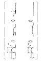
- FIG. 1 is a conceptual diagram showing folding of protrusions formed on a slab.
- the ratio between the height b and the width a of the protrusion d1 is larger than the ratio between the height b and the width a of the protrusion d10.
- the protrusion d1 having a large ratio between the height b and the width a is likely to be folded when the slab is rolled by an in-line mill. Oxide scale c1 on the surface of the slab may be caught in the folding part e where the protrusion d1 is folded.
- the protrusion d10 having a small ratio between the height b and the width a is not easily folded even when rolled by an in-line mill. For this reason, the folding part e does not generate
- the oxidized scale on the slab surface is removed in the next pickling step.
- the oxide scale c1 bitten into the slab folding portion e cannot be sufficiently removed by ordinary pickling.
- the oxide scale is exposed on the surface of the slab and the surface property of the slab deteriorates, and the surface of the slab after rolling is deteriorated. Defects may become apparent.
- an object of the present invention is to occur when a slab having a protrusion formed by a twin drum continuous casting apparatus is rolled by an in-line mill.
- An object of the present invention is to provide a slab manufacturing method and a continuous casting facility that can prevent the protrusions from bending without impairing productivity.
- a molten metal storage section is formed by a pair of cooling drums having dimples formed on the surface and a pair of side weirs, and the molten metal is rotated while the pair of cooling drums is rotated.
- a twin-drum type continuous casting apparatus that casts a slab having protrusions formed by the dimples from the molten metal stored in the storage unit, and a downstream side of the twin-drum type continuous casting apparatus, and cools the slab
- a cooling device that is disposed downstream of the cooling device, an in-line mill that performs one-pass rolling of the slab with a work roll of 10% or more by a work roll, and a downstream of the in-line mill
- a method for producing a slab by a continuous casting facility comprising a coiling device for winding the slab into a coil shape, wherein a rolling load and an advanced rate when the slab is rolled using a rolling analysis model
- the friction coefficient is calculated from the value, the lubrication conditions during rolling of the slab are controlled so that the friction coefficient falls within a predetermined range, and the deformation resistance model based on the Owanan theory and the approximate expression of Shida as the rolling analysis model
- the predetermined range is 0.15 or more and 0.25 or less when the coefficient of friction is calculated
- the height of the protrusion may be not less than 50 ⁇ m and not more than 100 ⁇ m.
- the lubrication condition is a supply amount of lubricating oil supplied to at least one of the work roll or the cast slab. May be.
- a molten metal reservoir is formed by a pair of cooling drums having dimples formed on the surface and a pair of side weirs, and the molten metal is rotated while rotating the pair of cooling drums.
- a twin-drum type continuous casting apparatus that casts a slab having protrusions formed by the dimples from the molten metal stored in the storage unit, and a downstream side of the twin-drum type continuous casting apparatus, and cools the slab
- a cooling device that is disposed downstream of the cooling device, an in-line mill that performs one-pass rolling of the slab with a work roll of 10% or more by a work roll, and a downstream of the in-line mill, Using a winding device for winding the piece into a coil, a measuring device for actually measuring the rolling load and the advanced rate of the slab rolled by the in-line mill, and a rolling analysis model, the rolling load and A friction coefficient is calculated from the measured value of the advanced rate, and a lubrication control device that controls the lubrication conditions during rolling of the slab so that the friction coefficient falls within a predetermined range, and as the rolling analysis model
- the friction coefficient is calculated from the measured values of the rolling load and the advanced rate using the Owanan theory and the equation of deformation resistance
- the height of the protrusion may be not less than 50 ⁇ m and not more than 100 ⁇ m.
- the lubrication control device calculates a supply amount of lubricating oil necessary for controlling the friction coefficient, and supplies the lubrication oil to the in-line mill.
- a friction coefficient adjuster that controls supply of lubricating oil may be provided.
- the present inventor has disclosed a method for producing a slab that can prevent the protrusion from being folded when an in-line mill is used to roll a slab having protrusions that are manufactured by a twin-drum type continuous casting facility and formed by dimples. I have studied earnestly. As a result, when rolling the slab with an in-line mill, the rolling analysis model is used to calculate the friction coefficient from the measured values of the rolling load and the advanced rate, so that the friction coefficient falls within a predetermined range.
- a method for controlling the lubrication conditions during rolling was conceived. By controlling the lubrication conditions of the slab so that the friction coefficient falls within a predetermined range, it is possible to prevent the protrusions formed on the surface of the slab from being bent without impairing the productivity.
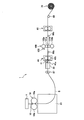
- FIG. 2 is an explanatory diagram showing a schematic configuration of a manufacturing process of a slab (thin slab) according to the present embodiment.
- the continuous casting facility 1 includes, for example, a tundish (storage device) T, a twin drum continuous casting device 10, an antioxidant device 20, a cooling device 30, 1 pinch roll device 40, in-line mill 100, second pinch roll device 60, and winding device 70.
- the twin-drum continuous casting apparatus 10 includes, for example, a pair of cooling drums 10a and 10b and a pair of side weirs (not shown) arranged on both sides in the axial direction of the pair of cooling drums 10a and 10b. And).
- the pair of cooling drums 10 a and 10 b and the side dam constitute a molten metal storage unit 15 that stores the molten metal supplied from the tundish T.
- the twin-drum type continuous casting apparatus 10 casts a slab from the molten metal stored in the molten metal storage unit 15 while rotating the pair of cooling drums 10a and 10b in opposite directions.
- the pair of cooling drums 10a and 10b includes a first cooling drum 10a and a second cooling drum 10b.
- the first cooling drum 10a and the second cooling drum 10b have a concave profile in which the center in the axial direction is slightly depressed.
- the 1st cooling drum 10a and the 2nd cooling drum 10b are comprised so that adjustment of the space
- the 1st cooling drum 10a and the 2nd cooling drum 10b are comprised so that a cooling medium (for example, cooling water) can distribute
- the cooling drums 10a and 10b can be cooled by circulating the cooling medium inside the cooling drums 10a and 10b. Further, dimples are formed on the surfaces of the cooling drums 10a and 10b.
- the first cooling drum 10a and the second cooling drum 10b are set such that, for example, the outer diameter is 800 mm, the drum body length (width) is 1500 mm, and the plate crown of the slab S in a steady state is 30 ⁇ m.
- the dimples may have a length in the rolling direction of 1.0 mm to 2.0 mm and a depth of 50 ⁇ m to 100 ⁇ m. That is, the length in the rolling direction of the protrusions formed by the dimples may be 1.0 mm to 2.0 mm, and the height of the protrusions formed by the dimples may be not less than 50 ⁇ m and not more than 100 ⁇ m.
- the outer diameters, drum body lengths (widths), and dimple shapes of the pair of cooling drums 10a and 10b are not limited thereto.
- a dummy sheet (not shown) is connected to the tip of the slab S, and casting is started.
- a dummy bar (not shown) having a thickness larger than that of the slab S is provided at the tip of the dummy sheet, and the dummy sheet is guided by the dummy bar.
- a hump (not shown) thicker than the plate thickness of the slab S is formed at the connection portion between the tip of the slab S and the dummy sheet.
- a rolling start method called a flying touch is performed in which rolling is started after the hump passes through the in-line mill 100.
- the antioxidant 20 is a device that performs a process for preventing the surface of the slab S immediately after casting from oxidizing and generating scale.
- the amount of oxygen can be adjusted by nitrogen gas. It is preferable to apply the antioxidant 20 as necessary in consideration of the steel type of the slab S to be cast.
- the cooling device 30 is a device that is disposed on the downstream side of the twin-drum type continuous casting device 10 and cools the slab S that has been subjected to an antioxidant treatment on the surface by the antioxidant device 20.
- the cooling device 30 includes, for example, a plurality of spray nozzles (not shown), and ejects cooling water from the spray nozzle to the surface (upper surface and lower surface) of the slab S according to the steel type. Cooling.
- a pair of feed rolls 87 may be arranged between the antioxidant device 20 and the cooling device 30.
- the pair of feed rolls 87 does not roll the slab S, but sandwiches the slab S by a pressing device (not shown), and the slab S between the pair of cooling drums 10a and 10b and the feed roll 87. While measuring the loop length, a conveying force in the horizontal direction is applied to the slab S so that the loop length is constant.
- the feed roll 87 is constituted by a pair of rolls having a roll diameter of 200 mm and a roll body length (width) of 2000 mm, for example.
- the first pinch roll device 40 is a pinch roll device disposed on the entry side of the inline mill 100.
- the first pinch roll device 40 does not roll the slab S, but an upper pinch roll 40a and a lower pinch roll 40b, a housing, a roll chock, a rolling load detection device, and a pressing device (first pinch roll device). None of them except 40 is shown.).
- Each of the upper pinch roll 40a and the lower pinch roll 40b has a hollow channel formed therein, and is configured to allow a cooling medium (for example, cooling water) to flow therethrough.
- the first pinch roll device 40 can be cooled by circulating the cooling medium.
- the upper pinch roll 40a and the lower pinch roll 40b may have, for example, a roll diameter of 400 mm and a roll trunk length (width) of 2000 mm.
- the upper pinch roll 40a and the lower pinch roll 40b are disposed via a roll chock in the housing, and are rotationally driven by a motor (not shown).
- the upper pinch roll 40a is connected to a pass line adjusting device (not shown) via an upper rolling load detection device (not shown), and the lower pinch roll 40b is a pressing device (not shown). .).
- the pressing load applied to the upper pinch roll 40a and the lower pinch roll 40b is detected.
- Tension is generated in the slab S between the first pinch roll device 40 and the inline mill 100.
- the slab S in the pair of pinch rolls 40a and 40b and the inline mill 100 is set so that the tension generated in the slab S between the first pinch roll device 40 and the inline mill 100 becomes a preset tension.
- the moving speed is controlled.
- the tension of the slab S between the first pinch roll device 40 and the inline mill 100 is detected by a tension roll 88a.
- a position detection device 41 that detects the position of the slab may be provided on the upstream side of the first pinch roll.
- the in-line mill 100 is a rolling device that is arranged on the downstream side of the cooling device 30 and the first pinch roll device 40 and rolls the slab S in one pass so that the slab S has a desired thickness.
- the in-line mill 100 is configured as a quadruple rolling mill. That is, the in-line mill 100 includes a pair of work rolls 101a and 101b and backup rolls 102a and 102b disposed above and below the work rolls 101a and 101b.
- “one-pass rolling” means that the slab S having the thickness of the slab S that has passed through the continuous casting apparatus 10 is rolled once in the in-line mill 100 to obtain a desired thickness on the outlet side of the in-line mill. It means that it is plastically deformed to have.
- the in-line mill 100 can roll the slab S to a desired thickness without impairing productivity by rolling the slab S at a reduction rate of 10% or more for one pass.
- the rolling reduction is preferably 15% or more, and more preferably 20% or more.
- the upper limit of the rolling reduction is not particularly limited, but if the rolling reduction in one-pass rolling is excessively high, the protrusion may be bent even if the friction coefficient is controlled as described later. is there. Therefore, the upper limit of the rolling reduction is preferably 40% or less, and more preferably 35% or less.
- H (mm) is the plate thickness of the slab S before rolling
- h (mm) is the plate thickness of the slab S after rolling.
- the in-line mill 100 may use, for example, work rolls 101a and 101b having a roll diameter of 400 mm and backup rolls 102a and 102b having a roll diameter of 1200 mm.
- the length of each roll may be the same, for example, 2000 mm.
- the in-line mill 100 is equipped with equipment for supplying lubricating oil to at least one of the work roll and the slab, and the lubrication conditions and the like can be controlled. Detailed description regarding the supply of the lubricating oil will be described later.
- the second pinch roll device 60 is disposed on the exit side of the inline mill 100. Similarly to the first pinch roll device 40, the second pinch roll device 60 does not roll the slab S, but an upper pinch roll and a lower pinch roll, a rolling load detection device, a pressing device (second device). These are not shown except for the pinch roll 60.).
- Each of the upper pinch roll and the lower pinch roll has a hollow channel formed therein, and is configured to allow a cooling medium (for example, cooling water) to flow therethrough.
- the pinch roll can be cooled by circulating the cooling medium.
- the upper pinch roll and the lower pinch roll may have a roll diameter of 400 mm and a roll body length (width) of 2000 mm.
- the upper pinch roll and the lower pinch roll are arranged via a roll chock in the housing, and are rotationally driven by a motor (not shown).
- a tension roll 88 b is disposed between the inline mill 100 and the second pinch roll device 60.
- the winding device 70 is a device that is disposed on the downstream side of the inline mill 100 and the second pinch roll device 60 and winds the slab S into a coil shape.
- a deflector roll 89 is disposed between the second pinch roll device 60 and the winding device 70.
- control of the lubrication conditions for preventing the slab protrusion from being bent by controlling the lubrication conditions during rolling of the slab by the in-line mill will be described in detail.
- an example of controlling the supply amount of the lubricating oil will be described as an example of the control of the lubrication conditions.
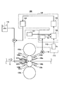
- FIG. 3 is a detailed view of the in-line mill 100.
- the in-line mill 100 includes a pair of work rolls 101a and 101b and backup rolls 102a and 102b disposed above and below the work rolls 101a and 101b.
- Cooling water supply nozzles 103a, 103b, 104a, 104b are provided before and after the in-line mill 100 in the rolling direction, and cooling water is supplied to the work rolls 101a, 101b.
- the work rolls 101a and 101b are cooled by the cooling water.
- draining plates 106a, 106b, 107a, 107b are provided between the cooling water supply nozzles 103a, 103b, 104a, 104b and the slab S so that the cooling water does not reach the slab.
- Lubricating oil supply nozzles 105 a and 105 b for supplying lubricating oil to at least one of the work roll surface and the cast piece are installed between the draining plates 107 a and 107 b installed on the entry side of the in-line mill 100 and the cast piece S.
- the lubricating conditions are controlled by controlling the amount of lubricating oil supplied by these lubricating oil supply nozzles 105a and 105b.
- Lubricating oil supplied from the lubricating oil supply nozzles 105 a and 105 b is stored in the lubricating oil tank 115.
- the lubricating oil may be, for example, an emulsion lubricating oil prepared by heating and stirring water mixed in the lubricating oil tank 115 and rolling lubricating oil.
- the produced emulsion lubricating oil is fed by the pump P and supplied from the lubricating oil supply nozzles 105a and 105b through the piping.
- the lubricating oil may be only the rolling lubricating oil without including a diluent such as water. Moreover, it is good also as emulsion lubricating oil by storing warm water and rolling lubricating oil in a separate tank, supplying separately into piping from each storage location, and mixing and shearing both after that.
- the lubricating oil itself may be sprayed onto the work roll like air atomization. Moreover, you may supply solid lubricating oil with respect to a slab.
- the casting on the rolling mill input side is changed even if the supply amount of the lubricating oil supply nozzles 105a and 105b is changed.
- the temperature of the slab may be controlled by cooling control of the cooling device 30 so that the temperature of the piece does not change.
- the continuous casting equipment in which the cooling water supply nozzles 104a and 104b, the draining plates 106a and 106b, and the lubricating oil supply nozzles 105a and 105b are provided on the rolling mill entrance side is shown. 104b and draining plates 106a and 106b are not essential and may be omitted.
- a measurement device 110 that measures information necessary for controlling the lubrication conditions and a lubrication control device 120 that controls the lubrication conditions of the in-line mill 100 are provided.
- the measuring device 110 has a load cell 111 and a plate speedometer 112. In the measuring apparatus 110, various values necessary for controlling the lubrication conditions are measured.
- the load cell 111 is disposed in a roll chock of the upper backup roll 102a and measures a rolling load.
- the plate speed meter 112 is provided on the exit side of the rolling mill and measures the plate speed (V 0 ) of the slab.
- the plate speedometer 112 may use, for example, a non-contact type speed measuring device.
- the lubrication control device 120 includes a work roll (WR) speed converter 121, a calculator 122, a friction coefficient calculator 123, and a friction coefficient adjuster 124.
- the lubrication control device 120 calculates the friction coefficient ⁇ based on the value detected and calculated by the measurement device 110 and controls the lubrication condition.
- the WR speed converter 121 calculates the work roll speed (V R ) from the number of rotations of the motor 116 using the ratio of the speed reducer (not shown) and the work roll diameter.
- the calculator 122 calculates the advanced rate (fs) from the slab plate speed and the work roll speed.
- the calculator 122 calculates the advanced rate (fs) from the following equation (1). That is, the calculator 122 calculates the advanced rate (fs) based on the plate speed (V o ) and the work roll speed (V R ).
- f S (V O / V R ⁇ 1) ⁇ 100 (1)
- the friction coefficient calculator 123 calculates the friction coefficient ⁇ based on the advanced rate (fs) calculated by the calculator 122 and the rolling load. Then, the friction coefficient adjuster 124 calculates the supply amount of lubricating oil necessary for controlling the friction coefficient ⁇ using the calculated friction coefficient ⁇ . The friction coefficient adjuster 124 further controls the supply of the lubricating oil supplied to the in-line mill 100 by controlling the pump P so that the amount of the lubricating oil supplied to control the calculated friction coefficient ⁇ is obtained. . In this way, the lubrication conditions are controlled using the measuring device 110 and the lubrication control device 120.
- the bending of the protrusion is caused by deformation in the roll bite that occurs during rolling of the slab, and is greatly affected by the shearing force of the surface layer in the roll bite.
- the shearing force is calculated by multiplying the compressive stress (rolling load) in the roll bite and the friction coefficient ⁇ .
- the rolling is basically performed without changing the conditions such as the steel type, rolling speed, and tension, and the rolling reduction is the same. Therefore, although the values of these parameters cannot be changed, the shear force of the surface layer in the roll bite in the in-line mill can be changed by adjusting the friction coefficient ⁇ . Therefore, the inventor of the present application examined an appropriate range of the friction coefficient ⁇ during rolling that can prevent the slab protrusion from folding.
- the width of the protrusions and the height of the protrusions were changed to verify the state of the slab protrusions after rolling.
- the results will be described with reference to FIGS.
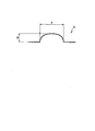
- the width A of the protrusion D was changed to 1 to 3 mm and the height B was changed to 50 to 200 ⁇ m to set the shape conditions of the five protrusions.
- the slabs on which these protrusions were formed were rolled by changing the friction coefficient ⁇ between 0.10 and 0.33.
- the friction coefficient ⁇ is a value calculated using a rolling analysis model based on the rolling conditions shown below.
- an equation of a deformation resistance model based on Orowan theory and an approximation formula of Shida was used as a rolling analysis model.
- the rolling of the slab in this verification was performed in the manufacturing process of the slab having the same configuration as in FIG.
- the slab used was a plain steel with a plate thickness of 2 mm and a plate width of 1200 mm.
- the acceleration rate of the cooling drum from the start of casting was 150 m / min / 30 seconds, and the rotational speed of the cooling drum in the steady state was 150 m / min.
- the initial profile of the cooling drum was processed so that the crown of the slab became 43 ⁇ m in a steady state.
- the slab rolling in this verification was performed with ordinary steel, the steel type to be rolled is not limited to ordinary steel.
- the in-line mill 100 a slab having a plate temperature of 1000 ° C. was rolled in one pass at a reduction rate of 30%, and the thickness of the slab on the inline mill exit side was set to 1.4 mm. Rolling in the in-line mill 100 was started after a dummy sheet passed through the in-line mill 100 and the plate crown of the slab became 150 ⁇ m or less. In this verification, rolling in the in-line mill 100 was started 15 seconds after the start of casting.
- a lubricating oil (melting point 0 ° C.) based on a synthetic ester (hindered complex ester) was supplied by an air atomization method.
- FIG. 5 shows the evaluation of the steel sheet under five conditions in which the width A and the height B of the protrusions are changed in the friction coefficient range of 0.10 to 0.33. Evaluation was shown by x in the steel plate which was unstable at the time of rolling, or the bending of the protrusion generate
- the protrusion D was folded when the friction coefficient ⁇ exceeded 0.25 regardless of the shape of the protrusion. If the friction coefficient ⁇ is not less than 0.15 and not more than 0.25, the protrusion D disappears and folds occur even if the width A and height B of the protrusion are in any shape of the conditions 1 to 5. There was no. When the friction coefficient ⁇ was less than 0.15, the protrusions disappeared, but the friction coefficient was small, and slipping occurred during rolling due to excessive lubrication, resulting in unstable rolling. In addition, excessive lubrication may occur due to an excessive supply amount of the lubricating oil.
- the basic unit of the lubricating oil deteriorates and the production cost of the slab increases.
- the friction coefficient ⁇ exceeded 0.25, the protrusion D was bent. From these results, the specified range of the friction coefficient ⁇ is set to a range of 0.15 to 0.25.
- the specified range of the friction coefficient ⁇ is set to 0.15 or more and 0.25 or less to control the lubrication conditions during rolling, thereby preventing the protrusions of the slab from being folded.
- the lubricating oil is not supplied, and water lubrication that also serves as roll cooling has been performed.
- the friction coefficient is high.
- the friction coefficient is calculated using the measured value of the rolling load and the advanced rate using the deformation resistance model expression by the approximate expression of the Owanan theory Shida as the rolling analysis model, the friction coefficient is 0.3. The range was about 0.4.
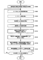
- FIG. 6 is a flowchart showing a lubrication condition control method according to this embodiment.
- the friction coefficient ⁇ can be calculated using a rolling analysis model.
- the value of the friction coefficient ⁇ is slightly different depending on the rolling analysis model used.
- the friction coefficient ⁇ is calculated using, for example, the Orowan theory disclosed in Non-Patent Document 1.
- Shida's approximate equation also disclosed in Non-Patent Document 1 is used.
- the roll diameter, tension, rolling load, sheet thickness, rolling speed, etc. can be measured at the time of rolling and can be handled as known numbers, so the unknown numbers are the friction coefficient ⁇ and the deformation resistance. Therefore, if two independent values are used, the friction coefficient and the deformation resistance can be calculated as a coupled problem. Therefore, for example, in the rolling analysis model that substitutes the measured values of rolling load and advanced rate and the rolling analysis model that assigns the calculated values of rolling load and advanced rate, the deformation resistance and friction coefficient are changed so that both values match. Thus, the friction coefficient ⁇ can be obtained by performing the calculation.
- the Owanan theory and the equation of the deformation resistance model based on the approximation formula of Shida were used as the rolling analysis model.
- the present invention is not limited to this example, and by using another rolling analysis model, the friction coefficient ⁇ can be calculated. You may ask for it.
- the approximate expression for calculating the friction coefficient ⁇ can be expressed as the following expression (2) using the advanced rate (f S ) and the rolling load (p). If necessary, a table may be formed according to the steel type, plate thickness, and rolling temperature.
- the constants a, b, and c of the approximate expression represented by Expression (2) may be obtained by multiple regression analysis.
- the friction coefficient ⁇ can be obtained using only the advanced rate (f S ) and rolling load (p) measured at the time of rolling.
- the calculation load can be reduced as compared with the method of calculating the friction coefficient ⁇ obtained by substituting.
- the constants a, b, and c in the approximate expression (3) may be obtained using, for example, multiple regression analysis.
- the lubricating oil supply amount Q refers to the net lubricating oil supply amount supplied to at least one unit surface area of the work roll or slab. In the case of emulsion lubricating oil, dilution of mixed water or the like Solvent is not included.
- step S100 in the target facility, the supply amount of the lubricating oil is changed in a steady state, and the rolling load (p) at each lubricating oil supply amount is acquired by the load cell, and the plate speed ( The advance rate (fs) is obtained based on V o ) and the work roll speed (V R ). Then, the friction coefficient calculator 123 calculates the friction coefficient at each lubricating oil supply amount from the rolling load and the advanced rate using, for example, the above equation (2). When the relationship between the plurality of lubricating oil supply amounts and the friction coefficient is acquired, the relationship between the lubricating oil supply amount and the friction coefficient ⁇ represented by, for example, the approximate expression (3) is acquired using these data. Is done. Based on the relationship between the lubricant supply amount obtained in step S100 and the friction coefficient ⁇ , the lubricant supply amount in the in-line mill 100 in actual operation is controlled.
- the rolling load is detected by the load cell 111 arranged in the roll chock of the upper backup roll (step S102).
- the WR speed converter 121 detects the rotation speed of the motor 116 that rotates the work rolls 101a and 101b, and calculates the work roll speed based on the rotation speed of the motor 116, the ratio of the speed reducer, and the work roll diameter.
- the plate speed of the slab S is detected by the plate speed meter 112 arranged on the exit side of the in-line mill 100 (step S106). In FIG. 6, although shown in the order of step S102, step S104, and step S106, these processes are performed in parallel.
- the advance rate is calculated by the calculator 122 using the work roll speed calculated in step S104 and the plate speed measured in step S106 (step S108).
- the friction coefficient ⁇ is calculated by the friction coefficient calculator 123 based on the detected and calculated rolling load and the advanced rate (step S110).
- the friction coefficient ⁇ may be calculated using, for example, the above equation (2).
- the lubrication oil supply amount is calculated by the friction coefficient adjuster 124.
- the friction coefficient adjuster 124 first obtains a difference ⁇ between the friction coefficient ⁇ calculated in step S110 and the target friction coefficient ⁇ aim (step S112).
- the target friction coefficient ⁇ aim is set to a value in the range of 0.15 to 0.25.
- the target friction coefficient ⁇ aim may be set from a range in which the specified range is further narrowed.
- the target friction coefficient ⁇ aim may be set to 0.20, for example.
- the friction coefficient adjuster 124 adjusts the lubricating oil corresponding to the difference ⁇ calculated in step S112 based on the relationship between the known friction coefficient ⁇ acquired in advance in step S100 and the lubricating oil supply amount Q.
- An amount (hereinafter also referred to as “lubricating oil adjustment amount ⁇ Q”) is calculated (step S114).
- the lubricant supply amount (ie, lubricant supply amount) ⁇ Q to be adjusted is calculated based on the difference ⁇ between the friction coefficient ⁇ calculated in step S112 and the target friction coefficient ⁇ aim .
- the friction coefficient adjuster 124 adjusts the currently set lubricating oil supply amount Q by the lubricating oil adjustment amount ⁇ Q corresponding to the difference ⁇ between the friction coefficient ⁇ and the target friction coefficient ⁇ aim, and the lubricating oil supply amount Change to Q + ⁇ Q (step S116).
- the friction coefficient adjuster 124 controls the pump P so that the amount of lubricating oil supplied by the lubricating oil supply nozzles 105a and 105b becomes the lubricating oil supply amount Q 0 + ⁇ Q. Thereby, the friction coefficient ⁇ is set to the target friction coefficient ⁇ aim .
- steps S102 to S116 are repeatedly performed during the rolling of the slab (S118).
- step S118 / Yes the control of the lubrication conditions in the in-line mill 100 is finished.
- step S118 / No the process starts again from step 202 in which the rolling load is detected by the load cell, and the process up to step S116 in which the lubricant supply amount is adjusted is repeated. Done.
- the method for controlling the lubrication conditions according to the present embodiment has been described.
- the supply amount of the lubricating oil to the work roll has been described.
- the lubrication condition is not limited to the supply amount of the lubricating oil as long as the friction coefficient ⁇ can be changed.
- the lubrication conditions may be controlled by other methods such as the type of the lubricant, the ratio of the lubricant and water in the emulsion lubricant, and the supply temperature of the lubricant.
- a synthetic ester or a synthetic ester mixed with vegetable oil may be used as a base oil.
- This example was performed in the manufacturing process of a slab having the same configuration as in FIG.
- ordinary steel having a plate thickness of 2 mm and a plate width of 1200 mm was used.
- the acceleration rate of the cooling drum from the start of casting was 150 m / min / 30 seconds, and the rotational speed of the cooling drum in the steady state was 150 m / min.
- the initial profile of the cooling drum was processed so that the crown of the slab became 43 ⁇ m in a steady state.
- the slab was rolled with ordinary steel, but the steel type to be rolled is not limited to ordinary steel.
- a slab having a plate temperature of 1000 ° C. was rolled in one pass at a reduction ratio of 30%, and the thickness of the slab on the inline mill exit side was set to 1.4 mm.
- Rolling in the in-line mill was started after the dummy sheet passed through the in-line mill and the plate crown of the slab became 150 ⁇ m or less. In this verification, rolling in an in-line mill was started 15 seconds after the start of casting.
- a lubricating oil (melting point 0 ° C.) based on a synthetic ester (hindered complex ester) was supplied by an air atomization method.
- the friction coefficient ⁇ was obtained by measuring the rolling load (p) and the advanced rate (fs) at the time of rolling and using the above formula (2).
- the lubricating oil can be obtained from the above formula (4).
- the adjustment amount ⁇ Q was calculated, the supply amount of the lubricating oil was controlled, and the supply amount of the lubricating oil was controlled with the target friction coefficient ⁇ aim 0.21. As a result, the slab was rolled so that the friction coefficient ⁇ was in the range of 0.19 to 0.23.
- the slab after rolling was pickled in the pickling step, and then further subjected to multi-pass rolling to a sheet thickness of 0.2 mm with a Sendzimer rolling mill having a diameter of 60 mm. In the pickling process, 10 ⁇ m of cutting was performed.
- the same rolling as in the example was performed without supplying the lubricating oil, and then the pickling in the pickling process, and then the same rolling as in the example was performed.
- the friction coefficient ⁇ at this time was 0.38 when calculated using the Owanan theory and the deformation resistance model equation by Shida's approximation as the rolling analysis model.
- 10 ⁇ m was cut.
- the rolling of 50 coils was performed in combination with the example and the comparative example, and the surface of the cast slab after rolling with a Zenzimer rolling mill was observed. As a result of surface observation, no surface defects were confirmed in the slab in the examples. On the other hand, in the comparative example, surface defects were confirmed in the slab. When the same rolling was performed again under the conditions of the comparative example, it was confirmed that 30 ⁇ m of cutting was necessary in the pickling process in order to eliminate surface defects. That is, in the comparative example, it was confirmed that it was necessary to perform the cutting of the slab three times as much as the example. From these results, by appropriately controlling the range of the coefficient of friction ⁇ when rolling the slab, it is possible to prevent the occurrence of folding of the protrusions, and further to improve the pickling efficiency by a factor of 3 compared to the prior art. all right.
- ADVANTAGE OF THE INVENTION According to this invention, it becomes possible to prevent the folding of the protrusion which generate
- a method for producing a slab and a continuous casting facility can be provided.
Landscapes
- Engineering & Computer Science (AREA)
- Mechanical Engineering (AREA)
- Continuous Casting (AREA)
- Metal Rolling (AREA)
Abstract
Priority Applications (5)
| Application Number | Priority Date | Filing Date | Title |
|---|---|---|---|
| CN201980016216.8A CN111788016B (zh) | 2018-03-02 | 2019-02-25 | 铸坯的制造方法及连续铸造设备 |
| JP2020503485A JP6984728B2 (ja) | 2018-03-02 | 2019-02-25 | 鋳片の製造方法及び連続鋳造設備 |
| BR112020016452-6A BR112020016452B1 (pt) | 2018-03-02 | 2019-02-25 | Método de produção de placa para equipamento de lingotamento contínuo e equipamento de lingotamento contínuo |
| US16/976,388 US12515246B2 (en) | 2018-03-02 | 2019-02-25 | Manufacturing method for slab and continuous casting equipment |
| KR1020207024611A KR102315597B1 (ko) | 2018-03-02 | 2019-02-25 | 주조편의 제조 방법 및 연속 주조 설비 |
Applications Claiming Priority (2)
| Application Number | Priority Date | Filing Date | Title |
|---|---|---|---|
| JP2018037945 | 2018-03-02 | ||
| JP2018-037945 | 2018-03-02 |
Publications (1)
| Publication Number | Publication Date |
|---|---|
| WO2019167868A1 true WO2019167868A1 (fr) | 2019-09-06 |
Family
ID=67805830
Family Applications (1)
| Application Number | Title | Priority Date | Filing Date |
|---|---|---|---|
| PCT/JP2019/007014 Ceased WO2019167868A1 (fr) | 2018-03-02 | 2019-02-25 | Procédé de fabrication de dalle et équipement de coulée continue |
Country Status (6)
| Country | Link |
|---|---|
| US (1) | US12515246B2 (fr) |
| JP (1) | JP6984728B2 (fr) |
| KR (1) | KR102315597B1 (fr) |
| CN (1) | CN111788016B (fr) |
| TW (1) | TW201938286A (fr) |
| WO (1) | WO2019167868A1 (fr) |
Families Citing this family (4)
| Publication number | Priority date | Publication date | Assignee | Title |
|---|---|---|---|---|
| AU2019247464B2 (en) | 2018-04-06 | 2024-08-29 | Nucor Corporation | High friction rolling of thin metal strip |
| TW202019582A (zh) * | 2018-10-22 | 2020-06-01 | 日商日本製鐵股份有限公司 | 鑄片的製造方法及控制裝置 |
| AU2019428242B2 (en) | 2019-02-08 | 2025-03-13 | Nucor Corporation | Ultra-high strength weathering steel and high friction rolling of the same |
| US11773465B2 (en) | 2019-09-19 | 2023-10-03 | Nucor Corporation | Ultra-high strength weathering steel for hot-stamping applications |
Citations (2)
| Publication number | Priority date | Publication date | Assignee | Title |
|---|---|---|---|---|
| JP2000343183A (ja) * | 1999-06-01 | 2000-12-12 | Nippon Steel Corp | 双ドラム式連続鋳造設備における板厚測定方法及び装置、板厚制御方法及び装置、記録媒体 |
| JP2017094340A (ja) * | 2015-11-18 | 2017-06-01 | 新日鐵住金株式会社 | 薄肉鋳片製造設備、及びピンチロールのレベリング方法 |
Family Cites Families (12)
| Publication number | Priority date | Publication date | Assignee | Title |
|---|---|---|---|---|
| GB633494A (en) * | 1947-04-22 | 1949-12-19 | Self Changing Gear Company Ltd | Improvements in or relating to centrifugally operated clutches |
| US4056140A (en) * | 1976-10-20 | 1977-11-01 | United States Steel Corporation | Method and mechanism for controlling forces in a continuous-casting machine |
| JPH05285601A (ja) | 1992-04-07 | 1993-11-02 | Nippon Steel Corp | 双ロール式連続鋳造装置 |
| DE19614760A1 (de) * | 1996-04-02 | 1997-10-09 | Mannesmann Ag | Verfahren zur Optimierung der Strangoberflächenqualität |
| FR2792560B1 (fr) | 1999-04-22 | 2001-06-01 | Usinor | Procede de coulee continue entre cylindres de bandes d'acier inoxydable austenitique d'excellente qualite de surface, et bandes ainsi obtenues |
| JP2000343103A (ja) | 1999-06-04 | 2000-12-12 | Nippon Steel Corp | 双ドラム式連続鋳造設備における鋳片の圧延開始方法、圧延制御装置及び記録媒体 |
| KR100668126B1 (ko) * | 2000-05-12 | 2007-01-16 | 신닛뽄세이테쯔 카부시키카이샤 | 박육 주편 연속 주조용 냉각 드럼의 가공 장치 |
| EP1634657B1 (fr) | 2003-06-13 | 2012-02-22 | JFE Steel Corporation | Procede et dispositif de refroidissement controle pour plaque en acier epaisse, et plaque en acier epaisse ainsi obtenue |
| JP2005246436A (ja) * | 2004-03-04 | 2005-09-15 | Nippon Steel & Sumikin Stainless Steel Corp | 溶接材料用高δフェライト含有オーステナイト系ステンレス鋼板およびその製造方法 |
| JP4355279B2 (ja) * | 2004-11-22 | 2009-10-28 | 新日本製鐵株式会社 | 冷間圧延における潤滑油供給方法 |
| CN103302255B (zh) * | 2012-03-14 | 2015-10-28 | 宝山钢铁股份有限公司 | 一种薄带连铸700MPa级高强耐大气腐蚀钢制造方法 |
| CN106391725B (zh) * | 2016-09-28 | 2018-05-01 | 燕山大学 | 一种适用于冷轧过程轧制压力随轧制速度变化预报方法 |
-
2019
- 2019-02-25 WO PCT/JP2019/007014 patent/WO2019167868A1/fr not_active Ceased
- 2019-02-25 KR KR1020207024611A patent/KR102315597B1/ko active Active
- 2019-02-25 CN CN201980016216.8A patent/CN111788016B/zh active Active
- 2019-02-25 JP JP2020503485A patent/JP6984728B2/ja active Active
- 2019-02-25 US US16/976,388 patent/US12515246B2/en active Active
- 2019-02-26 TW TW108106523A patent/TW201938286A/zh unknown
Patent Citations (2)
| Publication number | Priority date | Publication date | Assignee | Title |
|---|---|---|---|---|
| JP2000343183A (ja) * | 1999-06-01 | 2000-12-12 | Nippon Steel Corp | 双ドラム式連続鋳造設備における板厚測定方法及び装置、板厚制御方法及び装置、記録媒体 |
| JP2017094340A (ja) * | 2015-11-18 | 2017-06-01 | 新日鐵住金株式会社 | 薄肉鋳片製造設備、及びピンチロールのレベリング方法 |
Also Published As
| Publication number | Publication date |
|---|---|
| US12515246B2 (en) | 2026-01-06 |
| US20200406321A1 (en) | 2020-12-31 |
| CN111788016B (zh) | 2022-04-19 |
| KR20200110795A (ko) | 2020-09-25 |
| KR102315597B1 (ko) | 2021-10-21 |
| TW201938286A (zh) | 2019-10-01 |
| CN111788016A (zh) | 2020-10-16 |
| JP6984728B2 (ja) | 2021-12-22 |
| BR112020016452A2 (pt) | 2020-12-15 |
| JPWO2019167868A1 (ja) | 2021-01-07 |
Similar Documents
| Publication | Publication Date | Title |
|---|---|---|
| WO2019167868A1 (fr) | Procédé de fabrication de dalle et équipement de coulée continue | |
| JP2830962B2 (ja) | 加熱圧延鋼の製造装置および方法 | |
| CN101039762B (zh) | 用于连续制造薄金属带材的方法和设备 | |
| JP5305829B2 (ja) | 線材の圧延方法 | |
| JP2020116587A (ja) | 圧延設備及び圧延方法 | |
| AT501044B1 (de) | Verfahren zum herstellen eines gegossenen stahlbandes | |
| JPH0761488B2 (ja) | 熱間鋼帯の製造方法および設備 | |
| US6463777B1 (en) | Method for the continuous production of a metal strip | |
| AT511657B1 (de) | Inbetriebnahme einer fertigwalzstrasse in einer giess-walz-verbundanlage | |
| JP5838959B2 (ja) | 鋼帯の圧延方法および鋼帯の圧延装置 | |
| JP4777161B2 (ja) | 調質圧延方法 | |
| JP5488197B2 (ja) | 鋼帯の誘導加熱方法 | |
| CN117840252A (zh) | 一种防止热轧带钢松卷的控制方法 | |
| JP6051941B2 (ja) | 差厚鋼板の製造装置および製造方法 | |
| EP1289687A1 (fr) | Procede et installation pour fabriquer une bande de metal | |
| JP6079344B2 (ja) | 板幅方向に板厚差を有する差厚鋼板の製造装置および製造方法 | |
| BR112020016452B1 (pt) | Método de produção de placa para equipamento de lingotamento contínuo e equipamento de lingotamento contínuo | |
| JP6977468B2 (ja) | 連続鋳造設備及び圧延方法 | |
| AT511674B1 (de) | Inbetriebnahme einer fertigwalzstrasse in einer giess-walz-verbundanlage | |
| JP3848618B2 (ja) | 冷間圧延工程における板幅制御方法 | |
| JP4622488B2 (ja) | 熱間圧延における金属帯の巻取方法およびそれを用いた熱延金属帯の製造方法 | |
| JP3240978B2 (ja) | 連続鋳造鋳片の製造方法 | |
| JP4581787B2 (ja) | 熱間圧延における潤滑剤供給方法 | |
| JP2018167285A (ja) | 双ドラム式連続鋳造設備における圧延設備及び圧延方法 | |
| JP4402680B2 (ja) | 表面肌が良好な酸洗材の製造方法及びその装置 |
Legal Events
| Date | Code | Title | Description |
|---|---|---|---|
| 121 | Ep: the epo has been informed by wipo that ep was designated in this application |
Ref document number: 19761421 Country of ref document: EP Kind code of ref document: A1 |
|
| ENP | Entry into the national phase |
Ref document number: 2020503485 Country of ref document: JP Kind code of ref document: A |
|
| ENP | Entry into the national phase |
Ref document number: 20207024611 Country of ref document: KR Kind code of ref document: A |
|
| NENP | Non-entry into the national phase |
Ref country code: DE |
|
| REG | Reference to national code |
Ref country code: BR Ref legal event code: B01A Ref document number: 112020016452 Country of ref document: BR |
|
| ENP | Entry into the national phase |
Ref document number: 112020016452 Country of ref document: BR Kind code of ref document: A2 Effective date: 20200812 |
|
| 122 | Ep: pct application non-entry in european phase |
Ref document number: 19761421 Country of ref document: EP Kind code of ref document: A1 |
|
| WWG | Wipo information: grant in national office |
Ref document number: 16976388 Country of ref document: US |