WO2019171663A1 - Length measurement system, vehicle coupling system, length measurement method, and program - Google Patents
Length measurement system, vehicle coupling system, length measurement method, and program Download PDFInfo
- Publication number
- WO2019171663A1 WO2019171663A1 PCT/JP2018/042563 JP2018042563W WO2019171663A1 WO 2019171663 A1 WO2019171663 A1 WO 2019171663A1 JP 2018042563 W JP2018042563 W JP 2018042563W WO 2019171663 A1 WO2019171663 A1 WO 2019171663A1
- Authority
- WO
- WIPO (PCT)
- Prior art keywords
- vehicle
- electronically connected
- connection system
- group
- distance
- Prior art date
- Legal status (The legal status is an assumption and is not a legal conclusion. Google has not performed a legal analysis and makes no representation as to the accuracy of the status listed.)
- Ceased
Links
Images





Classifications
-
- B—PERFORMING OPERATIONS; TRANSPORTING
- B60—VEHICLES IN GENERAL
- B60W—CONJOINT CONTROL OF VEHICLE SUB-UNITS OF DIFFERENT TYPE OR DIFFERENT FUNCTION; CONTROL SYSTEMS SPECIALLY ADAPTED FOR HYBRID VEHICLES; ROAD VEHICLE DRIVE CONTROL SYSTEMS FOR PURPOSES NOT RELATED TO THE CONTROL OF A PARTICULAR SUB-UNIT
- B60W30/00—Purposes of road vehicle drive control systems not related to the control of a particular sub-unit, e.g. of systems using conjoint control of vehicle sub-units
- B60W30/14—Adaptive cruise control
- B60W30/16—Control of distance between vehicles, e.g. keeping a distance to preceding vehicle
- B60W30/165—Automatically following the path of a preceding lead vehicle, e.g. "electronic tow-bar"
-
- G—PHYSICS
- G08—SIGNALLING
- G08G—TRAFFIC CONTROL SYSTEMS
- G08G1/00—Traffic control systems for road vehicles
- G08G1/16—Anti-collision systems
- G08G1/167—Driving aids for lane monitoring, lane changing, e.g. blind spot detection
-
- G—PHYSICS
- G01—MEASURING; TESTING
- G01S—RADIO DIRECTION-FINDING; RADIO NAVIGATION; DETERMINING DISTANCE OR VELOCITY BY USE OF RADIO WAVES; LOCATING OR PRESENCE-DETECTING BY USE OF THE REFLECTION OR RERADIATION OF RADIO WAVES; ANALOGOUS ARRANGEMENTS USING OTHER WAVES
- G01S13/00—Systems using the reflection or reradiation of radio waves, e.g. radar systems; Analogous systems using reflection or reradiation of waves whose nature or wavelength is irrelevant or unspecified
- G01S13/88—Radar or analogous systems specially adapted for specific applications
- G01S13/93—Radar or analogous systems specially adapted for specific applications for anti-collision purposes
- G01S13/931—Radar or analogous systems specially adapted for specific applications for anti-collision purposes of land vehicles
-
- G—PHYSICS
- G08—SIGNALLING
- G08G—TRAFFIC CONTROL SYSTEMS
- G08G1/00—Traffic control systems for road vehicles
- G08G1/22—Platooning, i.e. convoy of communicating vehicles
-
- G—PHYSICS
- G01—MEASURING; TESTING
- G01S—RADIO DIRECTION-FINDING; RADIO NAVIGATION; DETERMINING DISTANCE OR VELOCITY BY USE OF RADIO WAVES; LOCATING OR PRESENCE-DETECTING BY USE OF THE REFLECTION OR RERADIATION OF RADIO WAVES; ANALOGOUS ARRANGEMENTS USING OTHER WAVES
- G01S13/00—Systems using the reflection or reradiation of radio waves, e.g. radar systems; Analogous systems using reflection or reradiation of waves whose nature or wavelength is irrelevant or unspecified
- G01S13/88—Radar or analogous systems specially adapted for specific applications
- G01S13/93—Radar or analogous systems specially adapted for specific applications for anti-collision purposes
- G01S13/931—Radar or analogous systems specially adapted for specific applications for anti-collision purposes of land vehicles
- G01S2013/9316—Radar or analogous systems specially adapted for specific applications for anti-collision purposes of land vehicles combined with communication equipment with other vehicles or with base stations
-
- G—PHYSICS
- G01—MEASURING; TESTING
- G01S—RADIO DIRECTION-FINDING; RADIO NAVIGATION; DETERMINING DISTANCE OR VELOCITY BY USE OF RADIO WAVES; LOCATING OR PRESENCE-DETECTING BY USE OF THE REFLECTION OR RERADIATION OF RADIO WAVES; ANALOGOUS ARRANGEMENTS USING OTHER WAVES
- G01S13/00—Systems using the reflection or reradiation of radio waves, e.g. radar systems; Analogous systems using reflection or reradiation of waves whose nature or wavelength is irrelevant or unspecified
- G01S13/88—Radar or analogous systems specially adapted for specific applications
- G01S13/93—Radar or analogous systems specially adapted for specific applications for anti-collision purposes
- G01S13/931—Radar or analogous systems specially adapted for specific applications for anti-collision purposes of land vehicles
- G01S2013/9325—Radar or analogous systems specially adapted for specific applications for anti-collision purposes of land vehicles for inter-vehicle distance regulation, e.g. navigating in platoons
Definitions
- the present invention relates to a length measurement system, a vehicle connection system, a length measurement method, and a program.
- Patent Document 1 describes an automatic follow-up traveling system that can shorten the time required to start platooning after electronic connection.
- Patent Document 1 The automatic following traveling system described in Patent Document 1 is assumed to be applied to a cargo transport vehicle such as a truck.
- a cargo transport vehicle such as a truck.
- the automatic follow-up traveling system can easily change the lane. It is possible to travel more appropriately.
- an object of the present invention is to provide a length measurement system, a vehicle connection system, a length measurement method, and a program capable of electronically connecting a plurality of vehicles and appropriately changing lanes.
- the length measurement system includes a lane adjacent to a lane in which an electronically connected vehicle group in which a plurality of vehicles are electronically connected is traveling ahead of a preceding vehicle in the electronically connected vehicle group.
- a vehicle detection unit that detects the position of the front vehicle that travels and the position of the rear vehicle that travels behind the subsequent vehicle of the electronic connection vehicle group
- the inter-vehicle communication unit that receives the position of the front vehicle detected by another vehicle different from the vehicle that detected the position of the front vehicle and the position of the rear vehicle, and the position of the rear vehicle, and the detected A distance between the front vehicle and the rear vehicle is calculated based on the position of the front vehicle and the position of the rear vehicle, and the position of the front vehicle and the position of the rear vehicle detected by the other vehicle.
- the vehicle connection system according to the second aspect of the present invention includes a plurality of vehicles provided with the length measurement system according to the first aspect of the present invention.
- the length measuring method includes a lane adjacent to a lane in which an electronically connected vehicle group in which a plurality of vehicles are electronically connected travels ahead of a preceding vehicle in the electronically connected vehicle group.
- a vehicle detection step for detecting a position of a traveling vehicle ahead and a position of a rear vehicle traveling behind a succeeding vehicle of the electronically coupled vehicle group; and among the plurality of vehicles constituting the electronically coupled vehicle group,
- the inter-vehicle communication step for receiving the position of the front vehicle detected by another vehicle different from the vehicle that detected the position of the front vehicle and the position of the rear vehicle, and the position of the rear vehicle, and detecting the detected
- a distance between the front vehicle and the rear vehicle is calculated based on the position of the front vehicle and the position of the rear vehicle, and the position of the front vehicle and the position of the rear vehicle detected by the other vehicle. Includes a control step, the.
- the program according to the fourth aspect of the present invention travels ahead of the preceding vehicle in the electronically connected vehicle group in a lane adjacent to the lane where the electronically connected vehicle group in which a plurality of vehicles are electronically connected travels.
- a vehicle detection step of detecting a position of a preceding vehicle and a position of a rear vehicle traveling behind a succeeding vehicle of the electronically connected vehicle group; and the front of the plurality of vehicles constituting the electronically connected vehicle group An inter-vehicle communication step for receiving the position of the front vehicle detected by another vehicle different from the vehicle that detected the position of the vehicle and the position of the rear vehicle, and the position of the rear vehicle, and the detected front vehicle And the position of the rear vehicle, and the position of the front vehicle and the position of the rear vehicle detected by the other vehicle, the distance between the front vehicle and the rear vehicle is calculated.
- To execute a control step to the computer that acts as the measuring system.
- a plurality of vehicles can be electronically connected and the lane can be changed appropriately.
- FIG. 1 is a block diagram showing a configuration of a length measurement system according to Embodiment 1 of the present invention.
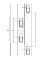
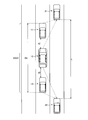
- FIG. 2 is a diagram for explaining an example of the operation of the vehicle connection system according to the first embodiment of the present invention.
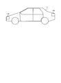
- FIG. 3 is a diagram illustrating an example of the configuration of the length measurement system according to the first embodiment of the present invention.
- FIG. 4 is a diagram illustrating an example of vehicle information stored in the length measurement system according to the first embodiment of the present invention.
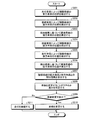
- FIG. 5 is a flowchart illustrating an example of an operation flow until the vehicle connection system according to the first embodiment of the present invention is configured.
- FIG. 6 is a flowchart illustrating an example of an operation flow when the vehicle connection system according to the first embodiment of the present invention changes lanes.
- FIG. 1 is a block diagram showing a configuration of a length measurement system according to Embodiment 1 of the present invention.
- FIG. 2 is a diagram for explaining an example of the operation of the vehicle connection system according to the first
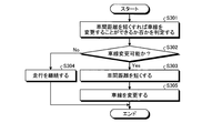
- FIG. 7 is a flowchart illustrating an example of an operation flow when the vehicle connection system according to the second embodiment of the present invention changes lanes.
- FIG. 8 is a flowchart illustrating an example of an operation flow when the vehicle connection system according to the third embodiment of the present invention changes lanes.
- FIG. 9 is a diagram for explaining an example of the operation of the vehicle connection system according to the fourth embodiment of the present invention.
- FIG. 10 is a flowchart illustrating an example of an operation flow when the vehicle connection system according to the fourth embodiment of the present invention changes lanes.
- FIG. 1 is a block diagram showing a configuration of a length measurement system according to Embodiment 1 of the present invention.
- FIG. 2 is a diagram for explaining an example of the operation of the coupled vehicle system.
- FIG. 3 is a diagram illustrating an example of a configuration example of the length measurement system according to the first embodiment of the present invention.
- the length measurement system 100 includes a vehicle detection unit 110, an inter-vehicle distance acquisition unit 120, an inter-vehicle communication unit 130, a storage unit 140, and a control unit 150.
- the length measurement system 100 is mounted on a private vehicle, for example.
- a private vehicle equipped with the length measurement system 100 travels in a platoon with electronic connection while appropriately detecting vehicles in adjacent lanes.
- Vehicle detection unit 110 detects vehicles traveling in front of and behind adjacent lanes.
- the vehicle detection unit 110 may always detect a vehicle in the adjacent lane, or may detect a vehicle in the adjacent lane only when it is desired to detect a vehicle in the adjacent lane.
- the vehicle detection unit 110 is, for example, a camera that captures an image.
- the vehicle detection unit 110 images a vehicle traveling in front of and behind the adjacent lane.
- the vehicle detection unit 110 detects the position of the vehicle by imaging a license plate or the like attached to a vehicle traveling in front of and behind the adjacent lane.
- FIG. 2 shows a case where two vehicles, the preceding vehicle 11 and the following vehicle 12, are electronically connected.
- the electronically connected vehicles are electronically connected so as to be continuous along the traveling direction of the vehicle.
- the same lane is set to a predetermined lane during normal driving except when changing lanes and turning left and right. Drive in a row while maintaining the distance between vehicles.
- the acceleration information of the preceding vehicle 11 is shared by the radar mounted on the front side of the following vehicle 12 and the inter-vehicle communication unit 130, thereby performing more precise control of the inter-vehicle distance.
- the following vehicle 12 automatically follows the preceding vehicle 11 while keeping the inter-vehicle distance d1 with the preceding vehicle 11 constant.
- the vehicle connection system 200 is configured by the preceding vehicle 11 and the subsequent vehicle 12.
- the vehicle detection unit 110 of the preceding vehicle 11 detects the position of the front vehicle 21 that travels ahead of the preceding vehicle 11 in the adjacent lane and the position of the rear vehicle 22 that travels behind the subsequent vehicle 12.
- the vehicle detection unit 110 of the subsequent vehicle 12 detects the position of the preceding vehicle 21 and the position of the subsequent vehicle 12. That is, the preceding vehicle 11 and the succeeding vehicle 12 measure the distance L between the front vehicle 21 and the rear vehicle 22.
- the preceding vehicle 11 may be driven by a person or may be automatically driven.
- the vehicle detection unit 110 is provided in front of and behind the preceding vehicle 11.
- the vehicle detection unit 110 may be provided in the vicinity of the license plate of the preceding vehicle 11.
- the vehicle detection unit 110 may be provided inside the preceding vehicle 11.
- a plurality of vehicle detection units 110 may be provided.
- the vehicle detection unit 110 may be provided to the front vehicle 11 at the center front, right front, left front, center rear, right rear, left rear, right side, and left side. Since the position where the vehicle detection unit 110 is provided is the same for the following vehicle 12 as well, description thereof is omitted.
- the inter-vehicle distance acquisition unit 120 acquires a distance from a preceding vehicle that is electronically connected.
- the inter-vehicle distance acquisition unit 120 acquires a distance from a preceding vehicle in order to keep the distance between the electronically connected vehicles constant.
- the inter-vehicle distance acquisition unit 120 of the following vehicle 12 acquires the distance between the preceding vehicle 11 and the following vehicle 12.
- the inter-vehicle distance acquisition unit 120 may be provided behind the preceding vehicle 11 and acquire the inter-vehicle distance from the subsequent vehicle 12.
- the inter-vehicle distance acquisition unit 120 can be realized by, for example, a millimeter wave radar.
- the inter-vehicle communication unit 130 performs inter-vehicle communication with other vehicles.
- the inter-vehicle communication unit 130 performs electronic connection by transmitting and receiving speed information, position information, vehicle information, and the like to and from other vehicles.
- the inter-vehicle communication unit 130 transmits information regarding whether the vehicle is operated manually or automatically between the electronically connected vehicles to other electronically connected vehicles.
- the inter-vehicle communication unit 130 transmits the information detected by the vehicle detection unit 110 to another electronically connected vehicle.
- the inter-vehicle communication unit 130 can be realized by, for example, a DCM (Data Communication Module).
- the storage unit 140 stores a control program for controlling each unit constituting the length measurement system 100.
- the storage unit 140 stores, for example, vehicle information such as the total length, vehicle width, and vehicle height of each electronically connected vehicle.
- storage part 140 has memorize
- the performance of the vehicle detection unit 110 is, when the vehicle detection unit 110 is a camera, focal length, resolution, frequency response characteristics, noise, gradation characteristics, dynamic range, color reproduction, uniformity, geometric distortion,
- the performance includes moiré, chromatic aberration, blooming, smear, flare, ghost, and compression distortion.
- the storage unit 140 stores the position of the vehicle detection unit 110 of each vehicle in the electronically connected vehicle group.
- the storage unit 140 may also be used for temporary storage of data in the length measurement system 100.
- the storage unit 140 is, for example, a semiconductor memory device such as a RAM (Random Access Memory), a ROM (Read Only Memory), or a flash memory, or a storage device such as a hard disk, a solid state drive, or an optical disk.
- the storage unit 140 may be an external storage device or the like that is connected wirelessly or by wire through a communication unit (not shown).
- FIG. 4 is a diagram illustrating an example of vehicle information of each vehicle stored in the storage unit 140.
- the vehicle information 300 shown in FIG. 4 includes vehicle information of each vehicle that is electronically connected.
- the preceding vehicle 11 may have a total length of “L1”, a vehicle width of “W1”, a vehicle height of “H1”, a position of the vehicle detection unit of “P1”, and a performance of the vehicle detection unit of “Q1”. It is shown.
- the control unit 150 determines a platoon of each vehicle when performing electronic connection based on the vehicle information.
- the control unit 150 controls each unit constituting the length measurement system 100. Specifically, the control unit 150 controls each unit constituting the length measurement system 100 by developing and executing a program stored in the storage unit 140. The control unit 150 is based on the position of the front vehicle 21 and the position of the rear vehicle 22 detected by the vehicle detection unit 110 of the preceding vehicle 11, and the position of the front vehicle 21 and the position of the rear vehicle 22 detected by the subsequent vehicle 12. The distance between the front vehicle 21 and the rear vehicle 22 is calculated. For example, the control unit 150 determines whether or not to change the lane of the vehicle connection system 200 based on the total length of the vehicle connection system 200 and the distance between the front vehicle 21 and the rear vehicle 22.
- the control unit 150 adjusts the inter-vehicle distance of the vehicle connection system 200 based on the total length of the vehicle connection system 200 and the distance between the front vehicle 21 and the rear vehicle 22. For example, the control unit 150 controls the speed of the vehicle connection system 200 based on the positional relationship among the preceding vehicle 11, the following vehicle 12, the front vehicle 21, and the rear vehicle 22. For example, the control unit 150 determines a platoon of the vehicle connection system 200 based on the vehicle information. The control unit 150 determines a platoon of the vehicle connection system 200 according to the performance of the vehicle detection unit 110.
- the control unit 150 can be realized by, for example, an electronic circuit including a CPU (Central Processing Unit).
- the control unit 150 includes a platoon determination unit 151, an inter-vehicle distance control unit 152, a speed control unit 153, a lane change determination unit 154, and an operation control unit 155.
- the convoy determining unit 151 determines the convoy of each vehicle when electronically connecting. Specifically, the platoon determination unit 151 determines the position of each vehicle in the vehicle connection system 200 and the inter-vehicle distance d1 of the vehicle connection system 200 based on the vehicle information 300 stored in the storage unit 140. At this time, the platoon determination unit 151 determines the vehicle width of the vehicle having the widest vehicle width as the vehicle width of the vehicle connection system 200 based on the vehicle information 300. The platoon determination unit 151 determines the vehicle height of the vehicle with the highest vehicle height among the vehicle heights of each vehicle as the vehicle height of the vehicle connection system 200 based on the vehicle information 300.
- the convoy determining unit 151 calculates the total length of the vehicle connection system 200 based on the vehicle information and the inter-vehicle distance. For example, in the example illustrated in FIG. 2, the platoon determination unit 151 calculates the total length D1 of the vehicle connection system 200 based on the total length of the preceding vehicle 11, the total length of the subsequent vehicle 12, and the inter-vehicle distance d1. The formation determination unit 151 calculates the position of the vehicle detection unit 110 of each vehicle. The platoon determination unit 151 preferably arranges the vehicle having the best performance of the vehicle detection unit 110 at the head based on the vehicle information 300. When the vehicle detection unit 110 is a camera, the formation determination unit 151 particularly preferably determines the formation based on the focal length of the camera.
- the platoon determination unit 151 may perform the length measurement in the front and rear directions with the four vehicles. The formation may be determined so that two of the units are arranged in front and the remaining two units are arranged behind. That is, when the number of vehicles that are electronically connected increases, the platoon determination unit 151 uses the vehicle detection unit 110 having the same performance among the vehicles to detect whether the front vehicle 21 and the rear vehicle 22 A convoy may be determined to measure the distance between them.
- the inter-vehicle distance control unit 152 controls the inter-vehicle distance of the vehicle connection system 200.
- the inter-vehicle distance control unit 152 controls the inter-vehicle distance d ⁇ b> 1 between the preceding vehicle 11 and the subsequent vehicle 12.
- the inter-vehicle distance control unit 152 displays an instruction for shortening or lengthening the inter-vehicle distance to the driver or informing the driver when a person is driving.
- the control signal for performing is output to a monitor or a speaker provided in the vehicle.
- the inter-vehicle distance control unit 152 outputs a control signal for accelerating or decelerating the vehicle to shorten or increase the inter-vehicle distance.
- the vehicle controls to a predetermined inter-vehicle distance based on the control signal.
- the inter-vehicle distance control unit 152 increases the inter-vehicle distance d1 when the vehicle detection unit 110 can detect a vehicle in an adjacent lane with high accuracy when the inter-vehicle distance is increased.
- the inter-vehicle distance control unit 152 increases the inter-vehicle distance d1 when the front vehicle 21 exists and the rear vehicle 22 does not exist.
- the inter-vehicle distance control unit 152 shortens the inter-vehicle distance d1 when the rear vehicle 22 exists and the front vehicle 21 does not exist.
- the inter-vehicle distance control unit 152 increases the inter-vehicle distance d1 when the succeeding vehicle 12 tries to detect the position of the front vehicle 21 and the preceding vehicle 11 cannot detect the position of the front vehicle 21 due to the shadow.
- the inter-vehicle distance control unit 152 increases the inter-vehicle distance d1. To do.
- the inter-vehicle distance control unit 152 shortens the inter-vehicle distance d1 when the rear vehicle 22 approaches the subsequent vehicle 12 and the subsequent vehicle 12 cannot detect the position of the rear vehicle.
- the inter-vehicle distance control unit 152 is based on, for example, the total distance D1 of the vehicle connection system 200 and the distance L between the front vehicle 21 and the rear vehicle 22 calculated by the lane change determination unit 154 described later.
- Control d1 The inter-vehicle distance d ⁇ b> 1 between the preceding vehicle 11 and the subsequent vehicle 12 is set such that, for example, the subsequent vehicle 12 approaches the preceding vehicle 11 or is separated from the preceding vehicle 11 by the control of the inter-vehicle distance control unit 152. It is controlled by doing.
- Speed control unit 153 controls the speed of the vehicle. Specifically, the speed control unit 153 displays an instruction to increase or decrease the speed when the person is driving, or to notify the driver by voice. The signal is output to a monitor or speaker provided in the vehicle. In the case of automatic driving, the speed control unit 153 outputs a control signal for accelerating or decelerating the vehicle to increase or decrease the speed. The vehicle controls to a predetermined speed based on the control signal. For example, when the distance L between the front vehicle 21 and the rear vehicle 22 is sufficiently wide, the speed control unit 153 determines the vehicle speed when the subsequent vehicle 12 and the rear vehicle 22 are approaching each other. Raise.
- the speed control unit 153 has a sufficiently large distance L between the front vehicle 21 and the rear vehicle 22, but when the preceding vehicle 11 and the front vehicle 21 are close to each other, Reduce speed.
- the case where the vehicle is approaching means, for example, that the distance is so close that the lane cannot be changed safely.
- the lane change determination unit 154 determines whether or not the vehicle connection system 200 can change lanes. Specifically, the lane change determination unit 154 determines whether the forward vehicle 21 and the backward vehicle 22 are based on the positions of the forward vehicle 21 and the backward vehicle 22 detected by the preceding vehicle 11 and the subsequent vehicle 12 by the triangulation method. A distance L to the vehicle 22 is calculated. The lane change determination unit 154 determines whether or not the vehicle connection system 200 can change the lane based on the total length D1 of the vehicle connection system 200, the distance L between the front vehicle 21 and the rear vehicle 22.
- the lane change determining unit 154 determines that the lane can be changed and, when a person is driving, a monitor provided with a control signal for displaying the fact to the driver or notifying the driver by voice. And output to the speaker.
- the lane change determining unit 154 determines that the lane can be changed by controlling the inter-vehicle distance or controlling the speed, and when a person is driving, displays that fact to the driver. Then, a control signal to be notified by voice is output to a monitor or speaker provided in the vehicle.
- the lane change determining unit 154 determines that the lane can be changed and outputs a control signal for changing the lane to the driving control unit 155 when the vehicle is in the automatic driving mode.
- the lane change determining unit 154 determines that the lane can be changed by controlling the inter-vehicle distance or controlling the speed, and when driving automatically, the inter-vehicle distance control unit 152 controls the inter-vehicle distance. After the control signal for outputting the control signal is output to the vehicle and the speed control unit 153 outputs the control signal for controlling the speed to the vehicle, the control signal for changing the lane is output to the driving control unit 155.
- the operation control unit 155 automatically drives the vehicle. Specifically, the driving control unit 155 controls the driving of the subsequent vehicle 12 so as to follow the preceding vehicle 11.
- the driving control unit 155 changes the vehicle lane in accordance with a control signal from the lane change determining unit 154. For example, the driving control unit 155 automatically drives the subsequent vehicle 12 during traveling, and cancels the automatic driving when the vehicle stops at the parking lot.
- FIG. 5 is a flowchart showing an example of the flow of operations until the vehicle connection system 200 according to the present embodiment is configured.
- the control unit 150 controls the speed of the subsequent vehicle 12 to be constant according to the preceding vehicle 11 (step S101). Then, the control unit 150 proceeds to step S102.
- the controller 150 controls the inter-vehicle distance d1 between the preceding vehicle 11 and the following vehicle 12 to be constant (step S102). Then, the control unit 150 proceeds to step S103.
- the control unit 150 calculates the total length D1 of the vehicle connection system 200 based on the vehicle information 300 and the inter-vehicle distance d1 (step S103). Then, the control unit 150 proceeds to step S104.
- the control unit 150 calculates the position of the vehicle detection unit 110 of the preceding vehicle 11 and the vehicle detection unit 110 of the subsequent vehicle 12 in the vehicle connection system 200 based on the vehicle information 300 and the total length D1 of the vehicle connection system 200. (Step S104). Then, the control unit 150 proceeds to step S105.
- control unit 150 sets the vehicle width of the vehicle having the wider vehicle width of the preceding vehicle 11 and the subsequent vehicle 12 as the vehicle width of the vehicle connection system 200 (step S105). Then, the control unit 150 proceeds to step S106.
- control unit 150 sets the vehicle height of the vehicle with the higher vehicle height of the preceding vehicle 11 and the subsequent vehicle 12 as the vehicle height of the vehicle connection system 200 (step S106). Then, the control unit 150 ends the process illustrated in FIG.
- FIG. 6 is a flowchart illustrating an example of an operation when the vehicle connection system 200 changes lanes.
- the vehicle connection system 200 detects the position of the vehicle 21 ahead of the adjacent lane by using the preceding vehicle 11 (step S201). Specifically, the vehicle connection system 200 detects the position of the forward vehicle 21 by the vehicle detection unit 110 of the preceding vehicle 11. Then, the vehicle connection system 200 proceeds to step S202.
- the vehicle connection system 200 detects the position of the vehicle 21 ahead of the adjacent lane by the following vehicle 12 (step S202). Specifically, the vehicle connection system 200 detects the position of the forward vehicle 21 by the vehicle detection unit 110 of the subsequent vehicle 12. For example, the vehicle connection system 200 calculates the position of the front vehicle 21 by the triangulation method based on the image captured by the preceding vehicle 11 and the image captured by the subsequent vehicle 12. Therefore, from the viewpoint of calculating the position of the preceding vehicle 21 accurately, it is preferable that the distance between the preceding vehicle 11 and the following vehicle 12 is increased. Then, the vehicle connection system 200 proceeds to step S203.
- Vehicle connection system 200 calculates the position of forward vehicle 21 based on the position of forward vehicle 21 detected by preceding vehicle 11 and the position of forward vehicle 21 detected by subsequent vehicle 12 (step S203). Specifically, the vehicle connection system 200 calculates the position of the front vehicle 21 by the triangulation method using any one of the preceding vehicle 11 and the following vehicle 12 by the control unit 150. Then, the vehicle connection system 200 proceeds to step S204.
- the vehicle connection system 200 detects the position of the rear vehicle 22 in the adjacent lane by the following vehicle 12 (step S204). Specifically, the vehicle connection system 200 detects the position of the rear vehicle 22 by the vehicle detection unit 110 of the rear vehicle 22. Then, the vehicle connection system 200 proceeds to step S205.
- the vehicle connection system 200 detects the position of the rear vehicle 22 in the adjacent lane using the preceding vehicle 11 (step S205). Specifically, the vehicle connection system 200 detects the position of the rear vehicle 22 by the vehicle detection unit 110 of the preceding vehicle 11. Then, the vehicle connection system 200 proceeds to step S206.
- the vehicle connection system 200 calculates the position of the rear vehicle 22 based on the position of the rear vehicle 22 detected by the preceding vehicle 11 and the position of the rear vehicle 22 detected by the subsequent vehicle 12 (step S206). Specifically, the vehicle connection system 200 calculates the position of the rear vehicle 22 by the triangulation method using any one of the preceding vehicle 11 and the following vehicle 12 by the control unit 150. Then, the vehicle connection system 200 proceeds to step S207.
- the vehicle connection system 200 calculates the distance L between the front vehicle 21 and the rear vehicle 22 based on the position of the front vehicle 21 calculated in step S203 and the position of the rear vehicle 22 calculated in step S206. Calculate (step S207). Specifically, the vehicle connection system 200 calculates a distance L between the front vehicle 21 and the rear vehicle 22 by using any one of the preceding vehicle 11 and the following vehicle 12. Then, the vehicle connection system 200 proceeds to step S208.
- the vehicle connection system 200 determines whether the lane can be changed to the adjacent lane (step S208). Specifically, in the vehicle connection system 200, the control unit 150 of any one of the preceding vehicle 11 and the following vehicle 12 controls the entire length D ⁇ b> 1 of the vehicle connection system 200, the front vehicle 21, and the rear vehicle 22. Based on the distance L, it is determined whether or not the electronically connected vehicle group can change lanes. Then, the vehicle connection system 200 proceeds to step S209.
- step S210 the vehicle connection system 200 controls the subsequent vehicle 12 so that the control unit 150 of the subsequent vehicle 12 changes the lane following the preceding vehicle 11.
- the vehicle connection system 200 may control the preceding vehicle 11 by the control unit 150 of the preceding vehicle 11 so as to change the lane depending on the following vehicle 12.
- the vehicle connection system 200 complete finishes the process of FIG.
- step S209 when it is determined that the lane cannot be changed (“No” in step S209), the vehicle connection system 200 proceeds to step S211 and continues the current travel (step S211). And the vehicle connection system 200 complete
- the vehicle connection system 200 when it is determined that the lane cannot be changed, the vehicle connection system 200 continues the current travel. However, when it is determined that the lane change is not possible, the vehicle connection system 200 may execute an operation for changing the lane.
- FIG. 7 is a flowchart showing a flow of an operation for shortening the inter-vehicle distance in order that the vehicle connection system 200 changes the lane when it is determined that the lane cannot be changed.
- the vehicle connection system 200 determines whether or not the lane can be changed if the distance between the preceding vehicle 11 and the following vehicle 12 is shortened (step S301). Specifically, the vehicle connection system 200 is configured such that the control unit 150 of the preceding vehicle 11 and the subsequent vehicle 12 controls the total length D1, the inter-vehicle distance d1, the front vehicle 21, and the rear of the vehicle connection system 200. Based on the distance L to the vehicle 22, it is determined whether or not the lane can be changed by shortening the inter-vehicle distance d1. Then, the vehicle connection system 200 proceeds to step S302.
- step S302 the vehicle connection system 200 proceeds to step S303, and shortens the inter-vehicle distance d1 between the preceding vehicle 11 and the following vehicle 12 (step S303). .
- the vehicle connection system 200 shortens the inter-vehicle distance d ⁇ b> 1 by causing the subsequent vehicle 12 to approach the preceding vehicle 11 by the control unit 150 of the subsequent vehicle 12. Then, the vehicle connection system 200 proceeds to step S305.
- step S302 when it is determined that the lane cannot be changed (“No” in step S302), the vehicle connection system 200 proceeds to step S304 and continues the current travel (step S304). In this case, the vehicle connection system 200 ends the process of FIG.
- the vehicle connection system 200 changes the lane after shortening the inter-vehicle distance d1 between the preceding vehicle 11 and the following vehicle 12 (step S305). Then, the vehicle connection system 200 ends the operation of FIG.
- FIG. 8 is a flowchart showing a flow of an operation for controlling the speed so that the vehicle connection system 200 changes the lane when it is determined that the lane cannot be changed.
- the vehicle connection system 200 determines whether or not the lane can be changed by controlling the speeds of the preceding vehicle 11 and the following vehicle 12 (step S401). For example, consider a situation where the distance L between the front vehicle 21 and the rear vehicle 22 is sufficiently wide, but the vehicle connection system 200 cannot change lanes because the following vehicle 12 and the rear vehicle 22 are close to each other. . In this case, the vehicle connection system 200 determines whether the lane can be changed by increasing the speed by using any one of the preceding vehicle 11 and the following vehicle 12 by the control unit 150. For example, consider a situation in which the distance between the front vehicle 21 and the rear vehicle 22 is sufficiently wide, but the vehicle connection system 200 cannot change lanes because the preceding vehicle 11 and the front vehicle 21 are close to each other. In this case, the vehicle connection system 200 determines whether the lane can be changed by reducing the speed by using any one of the preceding vehicle 11 and the following vehicle 12 by the control unit 150. Then, the vehicle connection system 200 proceeds to step S402.
- step S403 If it is determined that the lane can be changed (“Yes” in step S402), the vehicle connection system 200 proceeds to step S403, and controls the speeds of the preceding vehicle 11 and the following vehicle 12 (step S403). For example, the vehicle connection system 200 adjusts the speed by using one of the preceding vehicle 11 and the following vehicle 12. Then, the vehicle connection system 200 proceeds to step S405.
- step S402 when it is determined that the lane cannot be changed (“No” in step S402), the vehicle connection system 200 proceeds to step S404 and continues the current travel (step S404). In this case, the vehicle connection system 200 ends the process of FIG.
- the vehicle connection system 200 changes the lane after adjusting the speeds of the preceding vehicle 11 and the following vehicle 12 (step S405). Then, the vehicle connection system 200 ends the operation of FIG.
- the two vehicles are described as being electronically connected. However, this is merely an example and does not limit the present invention. In the present invention, three or more vehicles may be electronically connected.
- FIG. 9 is a diagram for explaining a method of measuring the inter-vehicle distance when three vehicles are electronically connected.
- the specific operation of the length measurement system 100 is the same as that when two vehicles are electronically connected, and thus description thereof will be omitted as appropriate.
- the preceding vehicle 11, the succeeding vehicle 12, and the intermediate vehicle 13 are electronically connected to form a vehicle connecting system 200A.
- the length measurement system 100 is mounted on each of the preceding vehicle 11, the subsequent vehicle 12, and the intermediate vehicle 13.
- the intermediate vehicle 13 travels following the preceding vehicle 11 while maintaining an inter-vehicle distance d2 with the preceding vehicle 11. Then, the following vehicle 12 travels following the intermediate vehicle 13 while maintaining an inter-vehicle distance d2 with the intermediate vehicle 13. Thereby, the full length D2 of the vehicle connection system 200A is maintained.
- FIG. 10 is a flowchart showing an example of the operation when the vehicle connection system 200A changes lanes.
- the vehicle connection system 200A detects the position of the front vehicle 21 in the adjacent lane by using the preceding vehicle 11 (step S501). Then, the vehicle connection system 200A proceeds to step S502.
- the vehicle connection system 200A detects the position of the vehicle 21 ahead of the adjacent lane by the intermediate vehicle 13 (step S502). Then, the vehicle connection system 200A proceeds to step S503.
- Vehicle connection system 200A calculates the position of forward vehicle 21 based on the position of forward vehicle 21 detected by preceding vehicle 11 and the position of forward vehicle 21 detected by intermediate vehicle 13 (step S503). Then, the vehicle connection system 200A proceeds to step S504.
- the vehicle connection system 200A detects the position of the rear vehicle 22 in the adjacent lane by the succeeding vehicle 12 (step S504). Then, the vehicle connection system 200A proceeds to step S505.
- the vehicle connection system 200A detects the position of the rear vehicle 22 in the adjacent lane by the intermediate vehicle 13 (step S505). Then, the vehicle connection system 200A proceeds to step S506.
- the vehicle connection system 200A calculates the position of the rear vehicle 22 based on the position of the rear vehicle 22 detected by the succeeding vehicle 12 and the position of the rear vehicle 22 detected by the intermediate vehicle 13 (step S506). Then, the vehicle connection system 200A proceeds to step S507.
- the vehicle connection system 200A determines the distance L between the front vehicle 21 and the rear vehicle 22 based on the position of the front vehicle 21 calculated in step S503 and the position of the rear vehicle 22 calculated in step S506. Calculate (step S507).
- the vehicle connection system 200A determines whether or not the lane can be changed to the adjacent lane (step S508).
- step S509 If it is determined that the lane can be changed (“Yes” in step S509), the vehicle connection system 200 proceeds to step S510 and changes the lane (step S510).
- step S509 when it is determined that the lane cannot be changed (“No” in step S509), the vehicle connection system 200A proceeds to step S511 and continues the current traveling (step S511). And vehicle connection system 200A complete
- the intermediate vehicle 13 is electronically connected so that the vehicle width of the intermediate vehicle 13 becomes the widest.
- the performance of the vehicle detection unit 110 of the preceding vehicle 11, the subsequent vehicle 12, and the intermediate vehicle 13 is different, the distance L between the front vehicle 21 and the rear vehicle 22 is accurately measured according to the performance. You may change the formation so that you can.
- the positions (coordinates) of the front vehicle and the rear vehicle in the adjacent lane are calculated with high accuracy from the shooting state of the cameras of the two vehicles at different positions by the triangulation method. Measure distance between cars. On the other hand, when measuring with one unit, it may be difficult to measure the length accurately. When measuring with high accuracy with one unit, a high-precision and expensive device is required.
- the distance measurement system measures the distance between the front vehicle traveling in the adjacent lane and the rear vehicle by mounting the length measurement system on each vehicle constituting the vehicle connection system.
- the control for changing the lane can be appropriately executed according to the distance.
- a several private vehicle can be electronically connected and it can drive
- a vehicle platoon constituting the vehicle connection system is determined based on vehicle information of each vehicle.
- highly accurate driving can be performed by electronically connecting the vehicle with the best camera performance at the top.
- the electronically connected vehicle can be appropriately driven or measured with high accuracy, for example, when going touring with a plurality of vehicles, an error occurs in the time to reach the destination. Because it does not, you can eliminate the time to wait for the opponent.
- the vehicle when traveling normally with electronic connection, at least the following vehicle does not need to be driven, so the leading vehicle may be driven in place of the driver of another vehicle, and the rest time may be reduced. And can drive safely.
Landscapes
- Engineering & Computer Science (AREA)
- Physics & Mathematics (AREA)
- General Physics & Mathematics (AREA)
- Radar, Positioning & Navigation (AREA)
- Remote Sensing (AREA)
- Transportation (AREA)
- Mechanical Engineering (AREA)
- Automation & Control Theory (AREA)
- Electromagnetism (AREA)
- Computer Networks & Wireless Communication (AREA)
- Control Of Driving Devices And Active Controlling Of Vehicle (AREA)
- Traffic Control Systems (AREA)
- Length Measuring Devices By Optical Means (AREA)
Abstract
Description
本発明は、測長システム、車両連結システム、測長方法、およびプログラムに関する。 The present invention relates to a length measurement system, a vehicle connection system, a length measurement method, and a program.
運転者が運転する先行車両に、無人の複数の車両を追従して走行させる技術が提案されている。 Technology has been proposed in which a plurality of unattended vehicles follow a preceding vehicle driven by a driver.
例えば、特許文献1には、電子連結をして隊列走行を開始するまでの時間を短くすることのできる自動追従走行システムが記載されている。 For example, Patent Document 1 describes an automatic follow-up traveling system that can shorten the time required to start platooning after electronic connection.
特許文献1に記載されている自動追従走行システムは、トラックなどの貨物輸送車に適用することを想定している。特許文献1において、隣接車線の前方を走行する前方車両と、後方を走行する後方車両との間の距離の測長精度を向上させることによって、自動追従走行システムは、車線変更し易くなるため、より適切に走行することができる。 The automatic following traveling system described in Patent Document 1 is assumed to be applied to a cargo transport vehicle such as a truck. In Patent Document 1, by improving the length measurement accuracy of the distance between the front vehicle traveling ahead of the adjacent lane and the rear vehicle traveling rearward, the automatic follow-up traveling system can easily change the lane. It is possible to travel more appropriately.
そこで、本発明は複数の車両を電子連結させ、適切に車線変更させることのできる測長システム、車両連結システム、測長方法、およびプログラムを提供することを課題とする。 Therefore, an object of the present invention is to provide a length measurement system, a vehicle connection system, a length measurement method, and a program capable of electronically connecting a plurality of vehicles and appropriately changing lanes.
本発明の第一の態様の測長システムは、複数の車両が電子連結されている電子連結車両群が走行する車線と隣接している車線において、前記電子連結車両群の先行車両よりも前方を走行する前方車両の位置と、前記電子連結車両群の後続車両よりも後方を走行する後方車両の位置とを検出する車両検出部と、前記電子連結車両群を構成する前記複数の車両のうち、前記前方車両の位置と、前記後方車両の位置とを検出した車両とは異なる他車両が検出した前記前方車両の位置と、前記後方車両の位置とを受信する車車間通信部と、検出した前記前方車両の位置および前記後方車両の位置と、前記他車両が検出した前記前方車両の位置および前記後方車両の位置とに基づいて、前記前方車両と、前記後方車両との間の距離を算出する制御部と、を前記複数の車両のそれぞれが備える。 The length measurement system according to the first aspect of the present invention includes a lane adjacent to a lane in which an electronically connected vehicle group in which a plurality of vehicles are electronically connected is traveling ahead of a preceding vehicle in the electronically connected vehicle group. Of the plurality of vehicles constituting the electronic connection vehicle group, a vehicle detection unit that detects the position of the front vehicle that travels and the position of the rear vehicle that travels behind the subsequent vehicle of the electronic connection vehicle group, The inter-vehicle communication unit that receives the position of the front vehicle detected by another vehicle different from the vehicle that detected the position of the front vehicle and the position of the rear vehicle, and the position of the rear vehicle, and the detected A distance between the front vehicle and the rear vehicle is calculated based on the position of the front vehicle and the position of the rear vehicle, and the position of the front vehicle and the position of the rear vehicle detected by the other vehicle. With control Each of the plurality of vehicle is provided.
本発明の第二の態様の車両連結システムは、本発明の第一の態様の測長システムを備えた複数の車両で構成される。 The vehicle connection system according to the second aspect of the present invention includes a plurality of vehicles provided with the length measurement system according to the first aspect of the present invention.
本発明の第三の態様の測長方法は、複数の車両が電子連結されている電子連結車両群が走行する車線と隣接している車線において、前記電子連結車両群の先行車両よりも前方を走行する前方車両の位置と、前記電子連結車両群の後続車両よりも後方を走行する後方車両の位置とを検出する車両検出ステップと、前記電子連結車両群を構成する前記複数の車両のうち、前記前方車両の位置と、前記後方車両の位置とを検出した車両とは異なる他車両が検出した前記前方車両の位置と、前記後方車両の位置とを受信する車車間通信ステップと、検出した前記前方車両の位置および前記後方車両の位置と、前記他車両が検出した前記前方車両の位置および前記後方車両の位置とに基づいて、前記前方車両と、前記後方車両との間の距離を算出する制御ステップと、を含む。 The length measuring method according to the third aspect of the present invention includes a lane adjacent to a lane in which an electronically connected vehicle group in which a plurality of vehicles are electronically connected travels ahead of a preceding vehicle in the electronically connected vehicle group. A vehicle detection step for detecting a position of a traveling vehicle ahead and a position of a rear vehicle traveling behind a succeeding vehicle of the electronically coupled vehicle group; and among the plurality of vehicles constituting the electronically coupled vehicle group, The inter-vehicle communication step for receiving the position of the front vehicle detected by another vehicle different from the vehicle that detected the position of the front vehicle and the position of the rear vehicle, and the position of the rear vehicle, and detecting the detected A distance between the front vehicle and the rear vehicle is calculated based on the position of the front vehicle and the position of the rear vehicle, and the position of the front vehicle and the position of the rear vehicle detected by the other vehicle. Includes a control step, the.
本発明の第四の態様のプログラムは、複数の車両が電子連結されている電子連結車両群が走行する車線と隣接している車線において、前記電子連結車両群の先行車両よりも前方を走行する前方車両の位置と、前記電子連結車両群の後続車両よりも後方を走行する後方車両の位置とを検出する車両検出ステップと、前記電子連結車両群を構成する前記複数の車両のうち、前記前方車両の位置と、前記後方車両の位置とを検出した車両とは異なる他車両が検出した前記前方車両の位置と、前記後方車両の位置とを受信する車車間通信ステップと、検出した前記前方車両の位置および前記後方車両の位置と、前記他車両が検出した前記前方車両の位置および前記後方車両の位置とに基づいて、前記前方車両と、前記後方車両との間の距離を算出する制御ステップと、を測長システムとして動作するコンピュータに実行させる。 The program according to the fourth aspect of the present invention travels ahead of the preceding vehicle in the electronically connected vehicle group in a lane adjacent to the lane where the electronically connected vehicle group in which a plurality of vehicles are electronically connected travels. A vehicle detection step of detecting a position of a preceding vehicle and a position of a rear vehicle traveling behind a succeeding vehicle of the electronically connected vehicle group; and the front of the plurality of vehicles constituting the electronically connected vehicle group An inter-vehicle communication step for receiving the position of the front vehicle detected by another vehicle different from the vehicle that detected the position of the vehicle and the position of the rear vehicle, and the position of the rear vehicle, and the detected front vehicle And the position of the rear vehicle, and the position of the front vehicle and the position of the rear vehicle detected by the other vehicle, the distance between the front vehicle and the rear vehicle is calculated. To execute a control step, to the computer that acts as the measuring system.
本発明によれば、複数の車両を電子連結させ、適切に車線変更させることができる。 According to the present invention, a plurality of vehicles can be electronically connected and the lane can be changed appropriately.
以下、図面を参照しながら、本発明の実施形態について詳細に説明する。なお、各図において同一または相当する部分には同一の符号を付して適宜説明は省略する。 Hereinafter, embodiments of the present invention will be described in detail with reference to the drawings. In the drawings, the same or corresponding parts are denoted by the same reference numerals, and description thereof will be omitted as appropriate.
[実施形態1]
図1と、図2と、図3とを用いて、本発明の実施形態1に係る測長システムについて説明する。図1は、本発明の実施形態1に係る測長システムの構成を示すブロック図である。図2は、連結車両システムの動作の一例を説明するための図である。図3は、本発明の実施形態1に係る測長システムの構成例の一例を示す図である。
[Embodiment 1]
A length measurement system according to the first embodiment of the present invention will be described with reference to FIG. 1, FIG. 2, and FIG. FIG. 1 is a block diagram showing a configuration of a length measurement system according to Embodiment 1 of the present invention. FIG. 2 is a diagram for explaining an example of the operation of the coupled vehicle system. FIG. 3 is a diagram illustrating an example of a configuration example of the length measurement system according to the first embodiment of the present invention.
図1に示すように、測長システム100は、車両検出部110と、車間距離取得部120と、車車間通信部130と、記憶部140と、制御部150と、を備える。本実施形態では、測長システム100は、例えば、自家用車に搭載される。測長システム100を搭載した自家用車は、隣接車線の車両を適切に検出しつつ、電子連結を行って隊列走行する。
As shown in FIG. 1, the length measurement system 100 includes a
車両検出部110は、隣接車線の前方および後方を走行する車両を検出する。車両検出部110は、例えば、隣接車線の車両を常に検出してもよいし、隣接車線の車両を検出したい場合にのみ隣接車線の車両を検出してもよい。車両検出部110は、例えば、画像を撮像するカメラである。この場合、車両検出部110は、隣接車線の前方および後方を走行する車両を撮像する。具体的には、車両検出部110は、隣接車線の前方および後方を走行する車両に取り付けられているナンバープレートなどを撮像することで車両の位置を検出する。
図2では、先行車両11と、後続車両12との2台の車両が電子連結されている場合を示している。ここで、電子連結された車両は、車両の進行方向に沿って連なるように電子的に連結されており、例えば、車線変更時、右左折時などを除く通常走行時は、同一車線を所定の車間距離を保ちつつ一列で走行する。電子連結では、後続車両12の前方に搭載したレーダ及び車車間通信部130によって先行車両11の加速度情報を共有することで、より精密な車間距離の制御を行う。具体的には、後続車両12は、先行車両11との車間距離d1を一定に保ちつつ、先行車両11を自動で追従走行する。これにより、先行車両11と、後続車両12とで車両連結システム200が構成される。この場合、先行車両11の車両検出部110は、隣接車線において先行車両11よりも前方を走行する前方車両21の位置と、後続車両12よりも後方を走行する後方車両22の位置とを検出する。同様に、後続車両12の車両検出部110は、前方車両21の位置と、後続車両12の位置とを検出する。すなわち、先行車両11と、後続車両12とは、前方車両21と、後方車両22との間の距離Lを測長する。なお、先行車両11は、人が運転していてもよいし、自動運転であってもよい。
FIG. 2 shows a case where two vehicles, the preceding
図3に示すように、車両検出部110は、先行車両11の車外の前方および後方に設けられる。車両検出部110は、例えば、先行車両11のナンバープレートの近傍に設けるようにすればよい。車両検出部110は、先行車両11の車内に設けてもよい。車両検出部110は、複数設けられていてもよい。例えば、車両検出部110は、先行車両11に対して、中央前、右前、左前、中央後、右後、左後、右側方、左側方に設けられていてもよい。後続車両12についても車両検出部110を設ける位置は同じなので、説明は省略する。
As shown in FIG. 3, the
車間距離取得部120は、電子連結されている先行車両との間の距離を取得する。車間距離取得部120は、電子連結されている各車両間の距離を一定に保つために先行車両との間の距離を取得する。図2では、先行車両11と、後続車両12との間の距離をd1に保つために、後続車両12の車間距離取得部120が、先行車両11と、後続車両12との間の距離を取得する。車間距離取得部120は、先行車両11の後方に設けられ、後続車両12との車間距離を取得してもよい。車間距離取得部120は、例えば、ミリ波レーダで実現することができる。
The inter-vehicle
車車間通信部130は、他の車両との間で、車車間通信を行う。車車間通信部130は、他の車両との間で速度情報や、位置情報、車両情報などを送受信することで電子連結を行う。車車間通信部130は、電子連結された車両間で、手動で運転しているか、自動で運転しているかに関する情報を電子連結された他の車両に送信する。車車間通信部130は、例えば、車両検出部110が検出した情報を、電子連結された他の車両に送信する。車車間通信部130は、例えば、DCM(Data Communication Module)で実現することができる。
The
記憶部140は、測長システム100を構成する各部を制御するための制御プログラムを記憶している。記憶部140は、例えば、電子連結された各車両の全長、車幅、車高などの車両情報を記憶している。記憶部140は、例えば、各車両に搭載されている車両検出部110の性能を記憶している。車両検出部110の性能とは、車両検出部110がカメラである場合には、焦点距離、解像度、周波数応答特性、ノイズ、階調特性、ダイナミックレンジ、色再現、一様性、幾何学歪、モアレ、色収差、ブルーミング、スミア、フレア、ゴースト、圧縮歪などの性能である。記憶部140は、電子連結車両群における、各車両の車両検出部110の位置を記憶している。記憶部140は、測長システム100におけるデータの一時記憶などにも利用してよい。記憶部140は、例えば、RAM(Random Access Memory)、ROM(Read Only Memory)、フラッシュメモリ(Flash Memory)などの半導体メモリ素子、または、ハードディスク、ソリッドステートドライブ、光ディスクなどの記憶装置である。また、記憶部140は、図示しない通信部によって無線または有線で接続される外部記憶装置などであってもよい。
The
図4を用いて、記憶部140が記憶している各車両の車両情報の一例について説明する。図4は、記憶部140が記憶している各車両の車両情報の一例を示す図である。
An example of vehicle information of each vehicle stored in the
図4に示す、車両情報300には、電子連結されている各車両の車両情報が含まれている。例えば、先行車両11は、全長が「L1」、車幅が「W1」、車高が「H1」、車両検出部の位置が「P1」、車両検出部の性能が「Q1」であることが示されている。具体的には後述するが、制御部150は、車両情報に基づいて、電子連結を行う際の各車両の隊列を決定する。
The
制御部150は、測長システム100を構成する各部を制御する。具体的には、制御部150は、記憶部140に記憶されているプログラムを展開して実行することによって、測長システム100を構成する各部を制御する。制御部150は、先行車両11の車両検出部110が検出した前方車両21の位置および後方車両22の位置と、後続車両12が検出した前方車両21の位置および後方車両22の位置とに基づいて、前方車両21と、後方車両22との間の距離を算出する。制御部150は、例えば、車両連結システム200の全長と、前方車両21と、後方車両22との間の距離に基づいて、車両連結システム200を車線変更させるか否かを判断する。制御部150は、例えば、車両連結システム200の全長と、前方車両21と、後方車両22との間の距離とに基づいて、車両連結システム200の車間距離を調整する。制御部150は、例えば、先行車両11と、後続車両12と、前方車両21と、後方車両22との位置関係に基づいて車両連結システム200の速度を制御する。制御部150は、例えば、車両情報に基づいて車両連結システム200の隊列を決定する。制御部150は、車両検出部110の性能に応じて車両連結システム200の隊列を決定する。制御部150は、例えば、CPU(Central Processing Unit)を含む電子的な回路などで実現することができる。制御部150は、隊列決定部151と、車間距離制御部152と、速度制御部153と、車線変更判断部154と、運転制御部155とを有する。
The control unit 150 controls each unit constituting the length measurement system 100. Specifically, the control unit 150 controls each unit constituting the length measurement system 100 by developing and executing a program stored in the
隊列決定部151は、電子連結する際の各車両の隊列を決定する。具体的には、隊列決定部151は、記憶部140が記憶している車両情報300に基づいて、各車両の車両連結システム200における位置と、車両連結システム200の車間距離d1とを決定する。この際、隊列決定部151は、車両情報300に基づいて、各車両の車幅のうち、最も車幅の広い車両の車幅を車両連結システム200の車幅として決定する。隊列決定部151は、車両情報300に基づいて、各車両の車高のうち、最も車高の高い車両の車高を車両連結システム200の車高として決定する。隊列決定部151は、車両情報と、車間距離とに基づいて、車両連結システム200の全長を算出する。例えば、図2に示す例でいうと、隊列決定部151は、先行車両11の全長と、後続車両12の全長と、車間距離d1とに基づいて、車両連結システム200の全長D1を算出する。隊列決定部151は、各車両の車両検出部110の位置を算出する。隊列決定部151は、車両情報300に基づいて、最も車両検出部110の性能がよい車両を先頭に配置することが好ましい。隊列決定部151は、車両検出部110がカメラである場合には、カメラの焦点距離に基づいて、隊列を決定することが特に好ましい。例えば、車両が5台以上の隊列で、4台の車両の車両検出部110の性能が同じである場合、隊列決定部151は、その4台の車両で前後の測長をするように、4台のうち2台を前、残りの2台を後に配置するように隊列を決定してもよい。すなわち、隊列決定部151は、電子連結された車両の数が多くなる場合には、各車両のうち同程度の性能の車両検出部110を利用して、前方車両21と、後方車両22との間の距離を測長するように、隊列を決定してもよい。
The convoy determining unit 151 determines the convoy of each vehicle when electronically connecting. Specifically, the platoon determination unit 151 determines the position of each vehicle in the
車間距離制御部152は、車両連結システム200の車間距離を制御する。例えば、図2に示す例でいうと、車間距離制御部152は、先行車両11と、後続車両12との間の車間距離d1を制御する。具体的には、車間距離制御部152は、人が運転している場合には、車間距離を短くしたり、長くしたりするような指示を、運転者に対して表示したり、音声で報知したりするための制御信号を車両が備えるモニタやスピーカに出力する。車間距離制御部152は、自動運転である場合には、車間距離を短くしたり、長くしたりするために、車両を加速または減速させるための制御信号を車両に出力する。車両は、制御信号に基づいて、所定の車間距離に制御する。車間距離制御部152は、例えば、車間距離を広げた方が、車両検出部110が精度よく隣接車線の車両を検出できる場合には、車間距離d1を長くする。車間距離制御部152は、例えば、前方車両21が存在し、後方車両22が存在しない場合には、車間距離d1を長くする。車間距離制御部152は、例えば、後方車両22が存在し、前方車両21が存在しない場合には、車間距離d1を短くする。車間距離制御部152は、例えば、後続車両12が前方車両21の位置を検出しようとした場合、先行車両11が陰となって前方車両21の位置を検出できない場合には、車間距離d1を長くする。車間距離制御部152は、例えば、先行車両11が後方車両22の位置を検出しようとした場合、後続車両12が陰となって後方車両22の位置を検出できない場合には、車間距離d1を長くする。車間距離制御部152は、例えば、後方車両22が後続車両12に接近し、後続車両12が後方車両の位置を検出できない場合には、車間距離d1を短くする。車間距離制御部152は、例えば、車両連結システム200の全長D1と、後述の車線変更判断部154によって算出される前方車両21と、後方車両22との間の距離Lとに基づいて、車間距離d1を制御する。先行車両11と、後続車両12との間の車間距離d1は、例えば、車間距離制御部152の制御によって、後続車両12を先行車両11に接近させたり、後続車両12を先行車両11から離したりすることで制御される。
The inter-vehicle distance control unit 152 controls the inter-vehicle distance of the
速度制御部153は、車両の速度を制御する。具体的には、速度制御部153は、人が運転している場合には、速度をあげたり、下げたりするような指示を、運転者に対して表示したり、音声で報知したりする制御信号を車両が備えるモニタやスピーカに出力する。速度制御部153は、自動運転である場合には、速度を上げたり、下げたりするために、車両を加速または減速させるための制御信号を車両に出力する。車両は、制御信号に基づいて、所定の速度に制御する。速度制御部153は、例えば、前方車両21と、後方車両22との間の距離Lは十分に開いているが、後続車両12と、後方車両22とが接近している場合には車両の速度を上げる。速度制御部153は、例えば、前方車両21と、後方車両22との間の距離Lは十分に開いているが、先行車両11と、前方車両21とが接近している場合には、車両の速度を下げる。ここで、接近している場合とは、例えば、安全に車線を変更することができない程度に、距離が近いことを意味する。
車線変更判断部154は、車両連結システム200が車線変更できるか否かを判断する。具体的には、車線変更判断部154は、先行車両11と、後続車両12とによって三角測量の方法で検出した前方車両21の位置および後方車両22の位置に基づいて、前方車両21と、後方車両22との間の距離Lを算出する。車線変更判断部154は、車両連結システム200の全長D1と、前方車両21と、後方車両22との間の距離Lに基づいて、車両連結システム200が車線変更できるか否かを判断する。車線変更判断部154は、車線変更できると判断し、かつ人が運転している場合には、その旨を運転者に対して表示したり、音声で報知したりする制御信号を車両が備えるモニタやスピーカに出力する。車線変更判断部154は、車間距離を制御したり、速度を制御したりすれば車線変更できると判断し、かつ人が運転している場合には、その旨を運転者に対して表示したり、音声で報知したりする制御信号を車両が備えるモニタやスピーカに出力する。車線変更判断部154は、車線変更できると判断し、かつ自動運転である場合には、車線変更させるための制御信号を運転制御部155に出力する。車線変更判断部154は、車間距離を制御したり、速度を制御したりすれば車線変更できると判断し、かつ自動で運転している場合には、車間距離制御部152が車間距離を制御するための制御信号を車両に出力し、速度制御部153が速度を制御するための制御信号を車両に出力した後、車線変更させるための制御信号を運転制御部155に出力する。
The lane
運転制御部155は、車両を自動運転する。具体的には、運転制御部155は、先行車両11を追従するように後続車両12の運転を制御する。運転制御部155は、車線変更判断部154からの制御信号に従って、車両を車線変更させる。運転制御部155は、例えば、走行中は後続車両12を自動運転し、駐車場に停車する場合などは自動運転を解除する。
The
図5を用いて、本実施形態に係る車両連結システム200を構成する動作について説明する。図5は、本実施形態に係る車両連結システム200を構成するまでの動作の流れの一例を示すフローチャートである。
The operation of the
制御部150は、先行車両11に合わせ、後続車両12の速度を一定に制御する(ステップS101)。そして、制御部150は、ステップS102に進む。
The control unit 150 controls the speed of the
制御部150は、先行車両11と、後続車両12との車間距離d1を一定に制御する(ステップS102)。そして、制御部150は、ステップS103に進む。
The controller 150 controls the inter-vehicle distance d1 between the preceding
制御部150は、車両情報300と、車間距離d1とに基づいて、車両連結システム200の全長D1を算出する(ステップS103)。そして、制御部150は、ステップS104に進む。
The control unit 150 calculates the total length D1 of the
制御部150は、車両情報300と、車両連結システム200の全長D1とに基づいて、先行車両11の車両検出部110と、後続車両12の車両検出部110との車両連結システム200における位置を算出する(ステップS104)。そして、制御部150は、ステップS105に進む。
The control unit 150 calculates the position of the
制御部150は、車両情報300に基づいて、先行車両11と、後続車両12とのうち、車幅の広い方の車両の車幅を車両連結システム200の車幅とする(ステップS105)。そして、制御部150は、ステップS106に進む。
Based on the
制御部150は、車両情報300に基づいて、先行車両11と、後続車両12とのうち、車高の高い方の車両の車高を車両連結システム200の車高とする(ステップS106)。そして、制御部150は、図5に図示の処理を終了する。
Based on the
図6を用いて、車両連結システム200が車線変更する動作について説明する。図6は、車両連結システム200が車線変更をする場合の動作の一例を示すフローチャートである。
The operation of the
まず、車両連結システム200は、先行車両11によって、隣接車線の前方車両21の位置を検出する(ステップS201)。具体的には、車両連結システム200は、先行車両11の車両検出部110によって、前方車両21の位置を検出する。そして、車両連結システム200は、ステップS202に進む。
First, the
車両連結システム200は、後続車両12によって、隣接車線の前方車両21の位置を検出する(ステップS202)。具体的には、車両連結システム200は、後続車両12の車両検出部110によって、前方車両21の位置を検出する。車両連結システム200は、例えば、先行車両11によって撮像した画像と、後続車両12によって撮像した画像とに基づいて、三角測量の方法で前方車両21の位置を算出する。そのため、前方車両21の位置を正確に算出するという観点からは、先行車両11と、後続車両12との距離は離れている方が好ましい。そして、車両連結システム200は、ステップS203に進む。
The
車両連結システム200は、先行車両11が検出した前方車両21の位置と、後続車両12が検出した前方車両21の位置とに基づいて、前方車両21の位置を算出する(ステップS203)。具体的には、車両連結システム200は、先行車両11と、後続車両12とのうちいずれかの制御部150によって、三角測量の方法で、前方車両21の位置を算出する。そして、車両連結システム200は、ステップS204に進む。
車両連結システム200は、後続車両12によって、隣接車線の後方車両22の位置を検出する(ステップS204)。具体的には、車両連結システム200は、後方車両22の車両検出部110によって、後方車両22の位置を検出する。そして、車両連結システム200は、ステップS205に進む。
The
車両連結システム200は、先行車両11によって、隣接車線の後方車両22の位置を検出する(ステップS205)。具体的には、車両連結システム200は、先行車両11の車両検出部110によって、後方車両22の位置を検出する。そして、車両連結システム200は、ステップS206に進む。
The
車両連結システム200は、先行車両11が検出した後方車両22の位置と、後続車両12が検出した後方車両22の位置とに基づいて、後方車両22の位置を算出する(ステップS206)。具体的には、車両連結システム200は、先行車両11と、後続車両12とのうちいずれかの制御部150によって、三角測量の方法で、後方車両22の位置を算出する。そして、車両連結システム200は、ステップS207に進む。
The
車両連結システム200は、ステップS203で算出された前方車両21の位置と、ステップS206で算出された後方車両22の位置とに基づいて、前方車両21と、後方車両22との間の距離Lを算出する(ステップS207)。具体的には、車両連結システム200は、先行車両11と、後続車両12とのうちいずれかの制御部150によって、前方車両21と、後方車両22との間の距離Lを算出する。そして、車両連結システム200は、ステップS208に進む。
The
車両連結システム200は、隣接車線に車線変更できるか否かを判定する(ステップS208)。具体的には、車両連結システム200は、先行車両11と、後続車両12とのうちいずれかの制御部150によって、車両連結システム200の全長D1と、前方車両21と、後方車両22との間の距離Lとに基づいて、電子連結車両群が車線変更できるか否かを判定する。そして、車両連結システム200は、ステップS209に進む。
The
車線変更できると判定された場合(ステップS209の「Yes」)、車両連結システム200は、ステップS210に進み、車線を変更する(ステップS210)。具体的には、車両連結システム200は、後続車両12の制御部150によって、先行車両11に追従して車線変更するように、後続車両12を制御する。車両連結システム200は、先行車両11の制御部150によって、後続車両12に従属して車線変更するように、先行車両11を制御してよい。そして、車両連結システム200は、図6の処理を終了する。
If it is determined that the lane can be changed (“Yes” in step S209), the
一方、車線変更できないと判定された場合(ステップS209の「No」)、車両連結システム200は、ステップS211に進み、現状の走行を継続する(ステップS211)。そして、車両連結システム200は、図6の処理を終了する。
On the other hand, when it is determined that the lane cannot be changed (“No” in step S209), the
図6では、車線変更できないと判定された場合、車両連結システム200は、現状の走行を継続している。しかしながら、車両連結システム200は、車線変更できないと判定された場合、車線変更を行うための動作を実行してもよい。
In FIG. 6, when it is determined that the lane cannot be changed, the
[実施形態2]
図7を用いて、実施形態2に係る車両連結システム200の動作について説明する。実施形態2に係る車両連結システム200は、車線変更できないと判断された場合、車線変更を行うために、車間距離を制御する。図7は、車線変更できないと判断された場合、車両連結システム200が車線変更を行うために車間距離を短くする動作の流れを示すフローチャートである。
[Embodiment 2]
The operation of the
まず、車両連結システム200は、先行車両11と、後続車両12との車間距離を短くすれば車線変更できるか否かを判定する(ステップS301)。具体的には、車両連結システム200は、先行車両11と、後続車両12とのうちいずれかの制御部150によって、車両連結システム200の全長D1と、車間距離d1と、前方車両21と、後方車両22との間の距離Lに基づいて、車間距離d1を短くすれば車線変更できるか否かを判定する。そして、車両連結システム200は、ステップS302に進む。
First, the
車線変更できると判定された場合(ステップS302の「Yes」)、車両連結システム200は、ステップS303に進み、先行車両11と、後続車両12との間の車間距離d1を短くする(ステップS303)。例えば、車両連結システム200は、後続車両12の制御部150によって、後続車両12を先行車両11に接近させることで、車間距離d1を短くする。そして、車両連結システム200は、ステップS305に進む。
When it is determined that the lane can be changed (“Yes” in step S302), the
一方、車線変更できないと判定された場合(ステップS302の「No」)、車両連結システム200は、ステップS304に進み、現状の走行を継続する(ステップS304)。この場合、車両連結システム200は、図7の処理を終了する。
On the other hand, when it is determined that the lane cannot be changed (“No” in step S302), the
車両連結システム200は、先行車両11と、後続車両12との車間距離d1を短くした後、車線を変更する(ステップS305)。そして、車両連結システム200は、図7の動作を終了する。
The
[実施形態3]
図8を用いて、実施形態3に係る車両連結システム200の動作について説明する。実施形態3に係る車両連結システム200は、車線変更できないと判断された場合、車線変更を行うために、速度を制御する。図8は、車線変更できないと判断された場合、車両連結システム200が車線変更を行うために速度を制御する動作の流れを示すフローチャートである。
[Embodiment 3]
The operation of the
まず、車両連結システム200は、先行車両11と、後続車両12との速度を制御すれば車線変更できるか否かを判定する(ステップS401)。例えば、前方車両21と、後方車両22との間の距離Lは十分に開いているが、後続車両12と、後方車両22とが接近しているため車両連結システム200が車線変更できない状況を考える。この場合、車両連結システム200は、先行車両11と、後続車両12とのうちいずれかの制御部150によって、速度を上げれば車線変更できるか否かを判定する。例えば、前方車両21と、後方車両22との間の距離は十分に開いているが、先行車両11と、前方車両21とが接近しているため車両連結システム200が車線変更できない状況を考える。この場合、車両連結システム200は、先行車両11と、後続車両12とのうちいずれかの制御部150によって、速度を下げれば車線変更できるか否かを判定する。そして、車両連結システム200は、ステップS402に進む。
First, the
車線変更できると判定された場合(ステップS402の「Yes」)、車両連結システム200は、ステップS403に進み、先行車両11と、後続車両12との速度を制御する(ステップS403)。例えば、車両連結システム200は、先行車両11と、後続車両12とのうちいずれかの制御部150によって、速度を調整する。そして、車両連結システム200は、ステップS405に進む。
If it is determined that the lane can be changed (“Yes” in step S402), the
一方、車線変更できないと判定された場合(ステップS402の「No」)、車両連結システム200は、ステップS404に進み、現状の走行を継続する(ステップS404)。この場合、車両連結システム200は、図8の処理を終了する。
On the other hand, when it is determined that the lane cannot be changed (“No” in step S402), the
車両連結システム200は、先行車両11と、後続車両12との速度を調整した後、車線を変更する(ステップS405)。そして、車両連結システム200は、図8の動作を終了する。
The
上述では2台の車両を電子連結するものとして説明したが、これは例示であり、本発明を限定するものではない。本発明は、3台以上の車両を電子連結させてもよい。 In the above description, the two vehicles are described as being electronically connected. However, this is merely an example and does not limit the present invention. In the present invention, three or more vehicles may be electronically connected.
[実施形態4]
図9を用いて、実施形態4に係る車両連結システム200Aが車間距離を測長する方法について説明する。実施形態4に係る車両連結システム200Aは、3台の車両を電子連結させて、車間距離を測長する。図9は、3台の車両を電子連結させた場合の車間距離を測長する方法を説明するための図である。なお、測長システム100の具体的な動作については、2台の車両を電子連結させる場合と同様なので、適宜説明は省略する。
[Embodiment 4]
A method for measuring the inter-vehicle distance by the
図9では、先行車両11と、後続車両12と、中間車両13とが電子連結され、車両連結システム200Aを構成している。この場合、先行車両11と、後続車両12と、中間車両13とのそれぞれに測長システム100が搭載される。
In FIG. 9, the preceding
車両連結システム200Aでは、中間車両13は、先行車両11との車間距離d2を保ちつつ、先行車両11に追従走行する。そして、後続車両12は、中間車両13との車間距離d2を保ちつつ、中間車両13に追従走行する。これにより、車両連結システム200Aの全長D2が保たれる。
In the
図10を用いて、車両連結システム200Aが車線変更する動作について説明する。図10は、車両連結システム200Aが車線変更をする場合の動作の一例を示すフローチャートである。
The operation of the
車両連結システム200Aは、先行車両11によって、隣接車線の前方車両21の位置を検出する(ステップS501)。そして、車両連結システム200Aは、ステップS502に進む。
The
車両連結システム200Aは、中間車両13によって、隣接車線の前方車両21の位置を検出する(ステップS502)。そして、車両連結システム200Aは、ステップS503に進む。
The
車両連結システム200Aは、先行車両11が検出した前方車両21の位置と、中間車両13が検出した前方車両21の位置とに基づいて、前方車両21の位置を算出する(ステップS503)。そして、車両連結システム200Aは、ステップS504に進む。
車両連結システム200Aは、後続車両12によって、隣接車線の後方車両22の位置を検出する(ステップS504)。そして、車両連結システム200Aは、ステップS505に進む。
The
車両連結システム200Aは、中間車両13によって、隣接車線の後方車両22の位置を検出する(ステップS505)。そして、車両連結システム200Aは、ステップS506に進む。
The
車両連結システム200Aは、後続車両12が検出した後方車両22の位置と、中間車両13が検出した後方車両22の位置とに基づいて、後方車両22の位置を算出する(ステップS506)。そして、車両連結システム200Aは、ステップS507に進む。
The
車両連結システム200Aは、ステップS503で算出された前方車両21の位置と、ステップS506で算出された後方車両22の位置とに基づいて、前方車両21と、後方車両22との間の距離Lを算出する(ステップS507)。
The
車両連結システム200Aは、隣接車線に車線変更できるか否かを判定する(ステップS508)。
The
車線変更できると判定された場合(ステップS509の「Yes」)、車両連結システム200は、ステップS510に進み、車線を変更する(ステップS510)。
If it is determined that the lane can be changed (“Yes” in step S509), the
一方、車線変更できないと判定された場合(ステップS509の「No」)、車両連結システム200Aは、ステップS511に進み、現状の走行を継続する(ステップS511)。そして、車両連結システム200Aは、図10の処理を終了する。
On the other hand, when it is determined that the lane cannot be changed (“No” in step S509), the
先行車両11と、後続車両12と、中間車両13との車幅がそれぞれ異なる場合、中間車両13の車幅が最も広くなるように電子連結させることが好ましい。先行車両11と、後続車両12と、中間車両13との車両検出部110の性能がそれぞれ異なる場合、性能に応じて、前方車両21と、後方車両22との間の距離Lを精度よく測長できるように隊列を変更してもよい。
When the vehicle widths of the preceding
上述のとおり、各実施形態では、位置が離れた2台の車両のカメラの撮影状態から、三角測量の方法で、隣接車線の前方車両と、後方車両の位置(座標)を高精度に算出し、車間距離を測長することができる。これに対して、1台で測定する場合、精度よく測長することが難しいことがある。1台で高精度に測定する場合、高精度で高価な装置が必要になる。 As described above, in each embodiment, the positions (coordinates) of the front vehicle and the rear vehicle in the adjacent lane are calculated with high accuracy from the shooting state of the cameras of the two vehicles at different positions by the triangulation method. Measure distance between cars. On the other hand, when measuring with one unit, it may be difficult to measure the length accurately. When measuring with high accuracy with one unit, a high-precision and expensive device is required.
上述のとおり、各実施形態では、車両連結システムを構成する各車両に測長システムを搭載することによって、隣接車線を走行している前方車両と、後方車両との距離を測長し、測長した距離に応じて、車線変更するための制御を適切に実行することができる。これにより、複数の自家用車を電子連結させて、適切に走行させることができる。 As described above, in each embodiment, the distance measurement system measures the distance between the front vehicle traveling in the adjacent lane and the rear vehicle by mounting the length measurement system on each vehicle constituting the vehicle connection system. The control for changing the lane can be appropriately executed according to the distance. Thereby, a several private vehicle can be electronically connected and it can drive | work appropriately.
また、各実施形態では、各車両の車両情報などに基づいて、車両連結システムを構成する車両の隊列を決定している。これにより、各実施形態は、全長、車幅、車高が異なる複数の車両で車両連結システムを構成した場合であっても、例えば、特定の車両が通過できないような道を選択することなく、適切に目的地まで走行することができる。 Further, in each embodiment, a vehicle platoon constituting the vehicle connection system is determined based on vehicle information of each vehicle. Thereby, even if each embodiment is a case where a vehicle connection system is constituted by a plurality of vehicles having different total lengths, vehicle widths, and vehicle heights, for example, without selecting a road through which a specific vehicle cannot pass, You can travel to your destination properly.
また、各実施形態では、カメラの性能が最もよい車両を先頭にして電子連結することで、高精度な運転ができる。 Also, in each embodiment, highly accurate driving can be performed by electronically connecting the vehicle with the best camera performance at the top.
また、各実施形態では、電子連結された車両を適切に運転したり、高精度に測長したりできるので、例えば、複数の車両でツーリングに行く際に、目的地に着く時間に誤差が発生しないので、相手を待つ時間を解消することができる。また、各実施形態では、電子連結して通常に走行している時には、少なくとも後続車両は運転しなくともよいので、先頭車両を他の車両の運転手と交代で運転すればよく、休憩時間が取れ安全に運転することができる。 Moreover, in each embodiment, since the electronically connected vehicle can be appropriately driven or measured with high accuracy, for example, when going touring with a plurality of vehicles, an error occurs in the time to reach the destination. Because it does not, you can eliminate the time to wait for the opponent. Further, in each embodiment, when the vehicle is traveling normally with electronic connection, at least the following vehicle does not need to be driven, so the leading vehicle may be driven in place of the driver of another vehicle, and the rest time may be reduced. And can drive safely.
11 先行車両
12 後続車両
13 中間車両
21 前方車両
22 後方車両
100 測長システム
110 車両検出部
120 車間距離取得部
130 車車間通信部
140 記憶部
150 制御部
151 隊列決定部
152 車間距離制御部
153 速度制御部
154 車線変更判断部
155 運転制御部
200,200A 車両連結システム
300 車両情報
DESCRIPTION OF
Claims (9)
前記電子連結車両群を構成する前記複数の車両のうち、前記前方車両の位置と、前記後方車両の位置とを検出した車両とは異なる他車両が検出した前記前方車両の位置と、前記後方車両の位置とを受信する車車間通信部と、
検出した前記前方車両の位置および前記後方車両の位置と、前記他車両が検出した前記前方車両の位置および前記後方車両の位置とに基づいて、前記前方車両と、前記後方車両との間の距離を算出する制御部と、を前記複数の車両のそれぞれが備えることを特徴とする測長システム。 In a lane adjacent to a lane in which an electronically connected vehicle group in which a plurality of vehicles are electronically connected travels, a position of a forward vehicle that travels ahead of a preceding vehicle in the electronically connected vehicle group, and the electronically connected vehicle group A vehicle detection unit that detects a position of a rear vehicle that travels behind the following vehicle;
Of the plurality of vehicles constituting the electronically connected vehicle group, the position of the front vehicle detected by another vehicle different from the vehicle that detected the position of the front vehicle and the position of the rear vehicle, and the rear vehicle A vehicle-to-vehicle communication unit that receives the position of
The distance between the front vehicle and the rear vehicle based on the detected position of the front vehicle and the position of the rear vehicle and the position of the front vehicle and the position of the rear vehicle detected by the other vehicle. Each of the plurality of vehicles is provided with a control unit that calculates the length measurement system.
前記電子連結車両群を構成する前記複数の車両のうち、前記前方車両の位置と、前記後方車両の位置とを検出した車両とは異なる他車両が検出した前記前方車両の位置と、前記後方車両の位置とを受信する車車間通信ステップと、
検出した前記前方車両の位置および前記後方車両の位置と、前記他車両が検出した前記前方車両の位置および前記後方車両の位置とに基づいて、前記前方車両と、前記後方車両との間の距離を算出する制御ステップと、を含むことを特徴とする測長方法。 In a lane adjacent to a lane in which an electronically connected vehicle group in which a plurality of vehicles are electronically connected travels, a position of a forward vehicle that travels ahead of a preceding vehicle in the electronically connected vehicle group, and the electronically connected vehicle group Vehicle detection step for detecting the position of a rear vehicle traveling behind the following vehicle,
Of the plurality of vehicles constituting the electronically connected vehicle group, the position of the front vehicle detected by another vehicle different from the vehicle that detected the position of the front vehicle and the position of the rear vehicle, and the rear vehicle Vehicle-to-vehicle communication step for receiving the position of
The distance between the front vehicle and the rear vehicle based on the detected position of the front vehicle and the position of the rear vehicle and the position of the front vehicle and the position of the rear vehicle detected by the other vehicle. And a control step for calculating the length.
前記電子連結車両群を構成する前記複数の車両のうち、前記前方車両の位置と、前記後方車両の位置とを検出した車両とは異なる他車両が検出した前記前方車両の位置と、前記後方車両の位置とを受信する車車間通信ステップと、
検出した前記前方車両の位置および前記後方車両の位置と、前記他車両が検出した前記前方車両の位置および前記後方車両の位置とに基づいて、前記前方車両と、前記後方車両との間の距離を算出する制御ステップと、を測長システムとして動作するコンピュータに実行させるためのプログラム。 In a lane adjacent to a lane in which an electronically connected vehicle group in which a plurality of vehicles are electronically connected travels, a position of a forward vehicle that travels ahead of a preceding vehicle in the electronically connected vehicle group, and the electronically connected vehicle group Vehicle detection step for detecting the position of a rear vehicle traveling behind the following vehicle,
Of the plurality of vehicles constituting the electronically connected vehicle group, the position of the front vehicle detected by another vehicle different from the vehicle that detected the position of the front vehicle and the position of the rear vehicle, and the rear vehicle Vehicle-to-vehicle communication step for receiving the position of
The distance between the front vehicle and the rear vehicle based on the detected position of the front vehicle and the position of the rear vehicle and the position of the front vehicle and the position of the rear vehicle detected by the other vehicle. A program for causing a computer operating as a length measurement system to execute the control step of calculating
Priority Applications (3)
| Application Number | Priority Date | Filing Date | Title |
|---|---|---|---|
| CN201880089034.9A CN111699518B (en) | 2018-03-09 | 2018-11-16 | Length measuring system, vehicle coupling system, length measuring method, and storage medium |
| EP18909119.2A EP3751535A4 (en) | 2018-03-09 | 2018-11-16 | Length measurement system, vehicle coupling system, length measurement method, and program |
| US17/009,803 US20200398840A1 (en) | 2018-03-09 | 2020-09-02 | Distance measuring system, vehicle coupling system, distance measuring method, and non-transitory storage medium |
Applications Claiming Priority (2)
| Application Number | Priority Date | Filing Date | Title |
|---|---|---|---|
| JP2018043415A JP7047482B2 (en) | 2018-03-09 | 2018-03-09 | Length measurement system, vehicle connection system, length measurement method, and program |
| JP2018-043415 | 2018-03-09 |
Related Child Applications (1)
| Application Number | Title | Priority Date | Filing Date |
|---|---|---|---|
| US17/009,803 Continuation US20200398840A1 (en) | 2018-03-09 | 2020-09-02 | Distance measuring system, vehicle coupling system, distance measuring method, and non-transitory storage medium |
Publications (1)
| Publication Number | Publication Date |
|---|---|
| WO2019171663A1 true WO2019171663A1 (en) | 2019-09-12 |
Family
ID=67847092
Family Applications (1)
| Application Number | Title | Priority Date | Filing Date |
|---|---|---|---|
| PCT/JP2018/042563 Ceased WO2019171663A1 (en) | 2018-03-09 | 2018-11-16 | Length measurement system, vehicle coupling system, length measurement method, and program |
Country Status (5)
| Country | Link |
|---|---|
| US (1) | US20200398840A1 (en) |
| EP (1) | EP3751535A4 (en) |
| JP (1) | JP7047482B2 (en) |
| CN (1) | CN111699518B (en) |
| WO (1) | WO2019171663A1 (en) |
Families Citing this family (5)
| Publication number | Priority date | Publication date | Assignee | Title |
|---|---|---|---|---|
| JP6725568B2 (en) * | 2018-03-13 | 2020-07-22 | 本田技研工業株式会社 | Vehicle control device, vehicle, vehicle control method, and program |
| EP4131208A4 (en) * | 2020-03-24 | 2023-03-29 | Mitsubishi Electric Corporation | ROUTE ARBITRATION DEVICE, AUTOMATED DRIVE CONTROL DEVICE AND AUTOMATED ROUTE ARBITRATION AND DRIVE SYSTEM |
| JP7439778B2 (en) * | 2021-02-24 | 2024-02-28 | トヨタ自動車株式会社 | taxi system |
| US11935404B2 (en) | 2021-03-24 | 2024-03-19 | Toyota Motor Engineering & Manufacturing North America, Inc. | Integrated congested mitigation for freeway non-recurring queue avoidance |
| JP7545589B2 (en) * | 2021-08-06 | 2024-09-04 | 日立Astemo株式会社 | Driving assistance device and driving assistance method |
Citations (4)
| Publication number | Priority date | Publication date | Assignee | Title |
|---|---|---|---|---|
| JPH10307997A (en) * | 1997-05-01 | 1998-11-17 | Fujitsu Ten Ltd | Device and method for controlling travelling in files |
| JP2000311299A (en) | 1999-04-28 | 2000-11-07 | Honda Motor Co Ltd | A formation method of a platoon of an automatic following system |
| JP2016146131A (en) * | 2015-02-09 | 2016-08-12 | アイシン・エィ・ダブリュ株式会社 | Convoy traveling management device and convoy traveling management program |
| JP2016149044A (en) * | 2015-02-13 | 2016-08-18 | アイシン・エィ・ダブリュ株式会社 | Platoon traveling management device and platoon traveling management program |
Family Cites Families (14)
| Publication number | Priority date | Publication date | Assignee | Title |
|---|---|---|---|---|
| JPH05217099A (en) * | 1992-02-05 | 1993-08-27 | Toyota Motor Corp | Vehicle drive controller |
| DE4313568C1 (en) * | 1993-04-26 | 1994-06-16 | Daimler Benz Ag | Method for guiding a lane change by a motor vehicle |
| JP3018920B2 (en) * | 1994-10-07 | 2000-03-13 | 三菱自動車工業株式会社 | Obstacle detection device for vehicles |
| JP3470287B2 (en) * | 1996-09-27 | 2003-11-25 | 本田技研工業株式会社 | Vehicle position display |
| KR100459476B1 (en) * | 2002-04-04 | 2004-12-03 | 엘지산전 주식회사 | Apparatus and method for queue length of vehicle to measure |
| US8818704B2 (en) * | 2010-10-18 | 2014-08-26 | Telenav, Inc. | Navigation system with road object detection mechanism and method of operation thereof |
| US8504233B1 (en) * | 2012-04-27 | 2013-08-06 | Google Inc. | Safely navigating on roads through maintaining safe distance from other vehicles |
| DE102013106769B4 (en) * | 2013-06-27 | 2021-06-10 | Create Electronic Optical Co., Ltd. | Tachograph with lane keeping and collision warning functions |
| CN105636849B (en) * | 2013-10-11 | 2018-05-18 | 日产自动车株式会社 | Travel controlling system and travel control method |
| FR3018941B1 (en) * | 2014-03-21 | 2017-07-07 | Thales Sa | PILOTAGE OF VEHICLES IN CONVOI |
| SE540272C2 (en) * | 2014-04-01 | 2018-05-22 | Scania Cv Ab | Procedure and system for risk assessment of lane change when driving a conductive vehicle on a roadway with at least two adjacent lanes |
| JP6303217B2 (en) * | 2015-10-28 | 2018-04-04 | 本田技研工業株式会社 | Vehicle control device, vehicle control method, and vehicle control program |
| CN206278020U (en) * | 2016-10-27 | 2017-06-27 | 延锋彼欧汽车外饰系统有限公司 | A kind of Integrated Early Warning System for preventing vehicle collision |
| CN107010064B (en) * | 2017-03-24 | 2019-06-14 | 奇瑞汽车股份有限公司 | Method and system for platoon formation driving |
-
2018
- 2018-03-09 JP JP2018043415A patent/JP7047482B2/en active Active
- 2018-11-16 WO PCT/JP2018/042563 patent/WO2019171663A1/en not_active Ceased
- 2018-11-16 EP EP18909119.2A patent/EP3751535A4/en not_active Withdrawn
- 2018-11-16 CN CN201880089034.9A patent/CN111699518B/en active Active
-
2020
- 2020-09-02 US US17/009,803 patent/US20200398840A1/en not_active Abandoned
Patent Citations (4)
| Publication number | Priority date | Publication date | Assignee | Title |
|---|---|---|---|---|
| JPH10307997A (en) * | 1997-05-01 | 1998-11-17 | Fujitsu Ten Ltd | Device and method for controlling travelling in files |
| JP2000311299A (en) | 1999-04-28 | 2000-11-07 | Honda Motor Co Ltd | A formation method of a platoon of an automatic following system |
| JP2016146131A (en) * | 2015-02-09 | 2016-08-12 | アイシン・エィ・ダブリュ株式会社 | Convoy traveling management device and convoy traveling management program |
| JP2016149044A (en) * | 2015-02-13 | 2016-08-18 | アイシン・エィ・ダブリュ株式会社 | Platoon traveling management device and platoon traveling management program |
Non-Patent Citations (1)
| Title |
|---|
| See also references of EP3751535A4 |
Also Published As
| Publication number | Publication date |
|---|---|
| JP7047482B2 (en) | 2022-04-05 |
| CN111699518B (en) | 2022-11-11 |
| EP3751535A1 (en) | 2020-12-16 |
| EP3751535A4 (en) | 2021-03-31 |
| JP2019159585A (en) | 2019-09-19 |
| US20200398840A1 (en) | 2020-12-24 |
| CN111699518A (en) | 2020-09-22 |
Similar Documents
| Publication | Publication Date | Title |
|---|---|---|
| WO2019171663A1 (en) | Length measurement system, vehicle coupling system, length measurement method, and program | |
| US9865162B2 (en) | Control method for traveling apparatus and traveling control apparatus | |
| KR102073496B1 (en) | Method and apparatus for detecting frame line of parking space | |
| US11422557B2 (en) | Information processing device and autonomous traveling control system including information processing device | |
| CN110139790A (en) | Control method for stopping and shutoff control unit | |
| JPWO2020008225A1 (en) | Driving support method and driving support device | |
| JP6174644B2 (en) | Image processing device | |
| US20180165966A1 (en) | Obstacle determination system and non-transitory computer-readable recording medium storing obstacle determination program | |
| JPWO2018150580A1 (en) | Travel plan correction device and travel plan correction method | |
| JP7339796B2 (en) | In-vehicle processing equipment | |
| WO2015125297A1 (en) | Local location computation device and local location computation method | |
| JP6500984B2 (en) | Vehicle control apparatus and vehicle control method | |
| CN111554116A (en) | In-vehicle processing device | |
| JP5172422B2 (en) | Driving support system | |
| KR101979928B1 (en) | System and method for estimating distance of front vehicle | |
| JP2010132029A (en) | Parking assistant device | |
| JP2008213581A (en) | Driving support method for vehicle and driving support device for vehicle | |
| JP2014130429A (en) | Photographing device and three-dimensional object area detection program | |
| JP6811497B1 (en) | Self-driving car | |
| KR20150022166A (en) | System and method for controlling mirror of vehicle using radar sensor | |
| US12485901B2 (en) | Travel support device, travel support method, and medium | |
| JP6908993B2 (en) | Information processing device, information processing method, and driving support system | |
| JP6967846B2 (en) | Object detection method and object detection device | |
| JP2013112068A (en) | Traveling course generation device and traveling control device | |
| CN112470456A (en) | Camera system for railway vehicle |
Legal Events
| Date | Code | Title | Description |
|---|---|---|---|
| 121 | Ep: the epo has been informed by wipo that ep was designated in this application |
Ref document number: 18909119 Country of ref document: EP Kind code of ref document: A1 |
|
| NENP | Non-entry into the national phase |
Ref country code: DE |
|
| ENP | Entry into the national phase |
Ref document number: 2018909119 Country of ref document: EP Effective date: 20200908 |