WO2019171899A1 - 油井管用ねじ継手 - Google Patents
油井管用ねじ継手 Download PDFInfo
- Publication number
- WO2019171899A1 WO2019171899A1 PCT/JP2019/005177 JP2019005177W WO2019171899A1 WO 2019171899 A1 WO2019171899 A1 WO 2019171899A1 JP 2019005177 W JP2019005177 W JP 2019005177W WO 2019171899 A1 WO2019171899 A1 WO 2019171899A1
- Authority
- WO
- WIPO (PCT)
- Prior art keywords
- screw
- joint
- box
- pin
- thread
- Prior art date
- Legal status (The legal status is an assumption and is not a legal conclusion. Google has not performed a legal analysis and makes no representation as to the accuracy of the status listed.)
- Ceased
Links
Images
Classifications
-
- F—MECHANICAL ENGINEERING; LIGHTING; HEATING; WEAPONS; BLASTING
- F16—ENGINEERING ELEMENTS AND UNITS; GENERAL MEASURES FOR PRODUCING AND MAINTAINING EFFECTIVE FUNCTIONING OF MACHINES OR INSTALLATIONS; THERMAL INSULATION IN GENERAL
- F16L—PIPES; JOINTS OR FITTINGS FOR PIPES; SUPPORTS FOR PIPES, CABLES OR PROTECTIVE TUBING; MEANS FOR THERMAL INSULATION IN GENERAL
- F16L15/00—Screw-threaded joints; Forms of screw-threads for such joints
- F16L15/001—Screw-threaded joints; Forms of screw-threads for such joints with conical threads
-
- E—FIXED CONSTRUCTIONS
- E21—EARTH OR ROCK DRILLING; MINING
- E21B—EARTH OR ROCK DRILLING; OBTAINING OIL, GAS, WATER, SOLUBLE OR MELTABLE MATERIALS OR A SLURRY OF MINERALS FROM WELLS
- E21B17/00—Drilling rods or pipes; Flexible drill strings; Kellies; Drill collars; Sucker rods; Cables; Casings; Tubings
- E21B17/02—Couplings; joints
- E21B17/04—Couplings; joints between rod or the like and bit or between rod and rod or the like
- E21B17/042—Threaded
-
- F—MECHANICAL ENGINEERING; LIGHTING; HEATING; WEAPONS; BLASTING
- F16—ENGINEERING ELEMENTS AND UNITS; GENERAL MEASURES FOR PRODUCING AND MAINTAINING EFFECTIVE FUNCTIONING OF MACHINES OR INSTALLATIONS; THERMAL INSULATION IN GENERAL
- F16L—PIPES; JOINTS OR FITTINGS FOR PIPES; SUPPORTS FOR PIPES, CABLES OR PROTECTIVE TUBING; MEANS FOR THERMAL INSULATION IN GENERAL
- F16L15/00—Screw-threaded joints; Forms of screw-threads for such joints
- F16L15/04—Screw-threaded joints; Forms of screw-threads for such joints with additional sealings
-
- F—MECHANICAL ENGINEERING; LIGHTING; HEATING; WEAPONS; BLASTING
- F16—ENGINEERING ELEMENTS AND UNITS; GENERAL MEASURES FOR PRODUCING AND MAINTAINING EFFECTIVE FUNCTIONING OF MACHINES OR INSTALLATIONS; THERMAL INSULATION IN GENERAL
- F16L—PIPES; JOINTS OR FITTINGS FOR PIPES; SUPPORTS FOR PIPES, CABLES OR PROTECTIVE TUBING; MEANS FOR THERMAL INSULATION IN GENERAL
- F16L15/00—Screw-threaded joints; Forms of screw-threads for such joints
- F16L15/06—Screw-threaded joints; Forms of screw-threads for such joints characterised by the shape of the screw-thread
Definitions
- the present invention relates to a threaded joint for oil well pipes connecting oil well pipes including tubing and casings used for exploration and production of oil wells and gas wells, and more particularly to a threaded joint for oil well pipes with reduced processing time and construction time.
- Threaded pipe joints are widely used for connecting steel pipes used in oil industry pipes such as oil well pipes.
- Conventionally, standard threaded joints for pipes defined in API (American Petroleum Institute) standards have been typically used for connecting steel pipes used in the search and production of oil and gas.
- Premium joints usually have a taper screw and a metal touch seal on the pipe end side of each pipe.
- each element which comprises the pin which is an external thread part provided in the one end side of a pipe, and the box which is an internal thread part screwed or fitted to the said external thread part provided in the one end side of a pipe.
- These elements are designed so that the male taper screw and female taper screw, and the male metal touch seal part and female metal touch seal part face each other when tightening the joint (the meaning of the threaded joint for pipes, the same shall apply hereinafter).
- the taper screw is necessary to fix the joint tightly.
- the metal touch seal portion ensures sealing performance by metal contact between the box and the pin in the region of the metal touch seal portion.
- the metal touch seal portion is provided at one or more locations in the axial direction (meaning of the pipe axis direction, hereinafter the same). At least one metal touch seal part is connected to the outer peripheral surface of the screwless part (hereinafter referred to as the nose) connected to the pin tip side screw end of the pin taper screw and to the box rear end side screw end of the box taper screw. Provided on the inner peripheral surface of the unthreaded portion (hereinafter referred to as a nose hole).
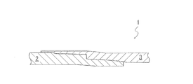
- FIG. 2 shows a pipe threaded joint 1 (tube threaded joint) described in Patent Document 1 as a prior art of an integral joint.
- the object of the invention described in Patent Document 1 is to produce a threaded joint for pipes with an appropriate seal while maintaining an appropriate rigidity, and the structural resistance (characteristics) of the joint to high loads, particularly to compressive loads. ) And to prevent the above characteristics from affecting the sealing function.
- a reinforcing section that protrudes from the metal touch seal portion of the non-threaded surface on the tip side of the box 3 to the tip of the box is provided, and the length of the reinforcing section or the wall thickness (wall thickness) Thickness) and the overall length of the reinforcing section of the box is set so as not to come into contact with the pipe (element tube portion) on the rear end side of the pin 2.
- Patent Document 1 does not mention optimization of the thread length of the joint. There was room for improvement in optimizing the screw length to achieve both productivity and joint shear fracture strength.
- an oil well pipe is charged into a well by connecting a plurality of pipes having joint parts (collectively referring to the male thread part and the female thread part) in series.
- joint parts collectively referring to the male thread part and the female thread part
- a relatively large tensile load acts on the joint as the pipe is closer to the ground. Therefore, an oil well pipe threaded joint is required as one of the important joint performances to have a strength capable of avoiding shear fracture such as fatigue fracture and tensile fracture.
- As a method of ensuring the strength of the joint portion it is required to provide a certain length of screw length for the joint portion.
- the shear fracture strength of the thread portion needs to exceed the tensile fracture strength of the joint portion, and the thread portion shear stress is one of the tensile stresses of the joint portion.
- / ⁇ Must be designed to be 3 times or less.
- the screw length of a joint part refers to the full length of the site
- the present invention has been made in view of the above problems, and an object thereof is to provide a threaded joint for oil country tubular goods in which the thread length of the joint portion is optimized and the processing time and construction time are reduced.
- the present inventors diligently studied to solve the above problems.
- the present inventors focused on a design in which the thread portion of the joint portion (referring to a male and female taper thread portion) has a minimum screw length that does not cause shear failure, and productivity and We have made extensive studies on threaded joints for oil well pipes that can achieve both shear fracture strength.
- the minimum screw length is required so that the ratio of the shear stress acting on the male and female taper threads and the tensile stress acting on the critical section of the joint is less than the specified value. It has been found that by defining L min (mm), shear failure at the threaded portion can be prevented.
- a pin provided with a male thread portion which is a male taper screw at one end of a steel pipe;
- a box provided with a female threaded portion which is a female taper screw fitted to the male threaded portion at one end of the steel pipe;
- Integra provided with a structure in which the pin and the box are in metal contact to seal a fluid at at least one of the outer peripheral surface side seal portion on the tube end side of the pin and the inner peripheral surface side seal portion on the tube end side of the box.
- Thread type oil well pipe joint A minimum value L min (mm) of a screw length L (mm) in the male taper screw and the female taper screw train is defined by the equation (1), The screw length L (mm) in the screw row satisfies the formula (2). Threaded joint for oil well pipes.
- L min ((t ⁇ (D ⁇ t)) / ( ⁇ t ⁇ D t / ⁇ 3)) ⁇ joint efficiency (1) L min ⁇ 1.0 ⁇ L ⁇ L min ⁇ 2.5 (2)
- t tube thickness (mm) of the raw tube part which is an unprocessed part of the box and the pin
- D Pipe diameter (mm) of the raw pipe part which is an unprocessed part of the box and the pin
- ⁇ t is the ratio of the effective screw length to the screw length L
- D t The average thread diameter (mm) of the thread valley in the taper screw having the shorter screw effective length of the box or pin
- Joint efficiency Tensile strength of joint part / tensile strength of raw pipe part
- the minimum necessary screw length (L min (mm)) is the screw length of the joint portion required for design in order for the screw portion to have strength capable of avoiding shear fracture. Refers to the minimum value (lower limit).
- the thread length (L (mm)) of the joint portion is the length of the portion of the joint portion where the male screw portion and the female screw portion are engaged (screw fitting portion) when the joint portion is screwed and fastened. (I.e., the thread length in the threaded row of male and female taper screws).
- the effective screw length is the sum of the axial lengths of the portions where the bottoms of the threaded portions of the male screw portion and the female screw portion are summed in the screw fitting portion, and is calculated for the male screw portion and the female screw portion, respectively.
- the effective screw length ratio ( ⁇ t ) is the ratio of the effective screw length to the screw length L, and the effective screw length is selected on the short side of the box or pin.
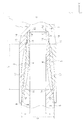
- FIG. 1 is a cross-sectional view of a threaded joint for oil well pipes illustrating an example of an embodiment of the present invention in the tube axis direction, and is a cross-sectional view showing a portion where a pin and a box are fastened.
- FIG. 2 is a cross-sectional view in the tube axis direction showing an example of a conventional threaded joint for oil country tubular goods.
- FIG. 1 is a cross-sectional view of a threaded joint 1 for an oil well pipe illustrating an embodiment of the present invention in the tube axis direction, and is a cross-sectional view showing a portion where a pin 2 and a box 3 are fastened (fitted) and its periphery. It is.
- FIG. 1 is also an explanatory diagram of the expressions (1) and (2) described later.
- the threaded joint 1 for oil well pipe of the present invention includes a pin 2 provided with a male threaded portion 4 that is a male tapered screw at one end of a steel pipe, and a female threaded portion that is a female tapered screw that fits the male threaded portion 4 at one end of the steel pipe. And a box 3 provided with 5. Further, the structure in which the pin 2 and the box 3 are in metal contact to seal the fluid is at least one of the outer peripheral surface side seal portion 9 on the tube end side of the pin 2 and the inner peripheral surface side seal portion 10 on the tube end side of the box 3 This is an integral type oil well pipe threaded joint 1 provided at a location.
- the minimum value L min (mm) of the screw length L (mm) in the thread row of the male and female taper screws is defined by the formula (1) described later, and the screw length L (mm) in the screw row is: The expression (2) described later is satisfied.
- the threaded joint 1 for oil country tubular goods of the present invention connects a steel pipe with a pin 2 and a box 3.
- the oil well pipe threaded joint 1 is a threaded joint (premium joint) in which a pin 2 and a box 3 are coupled by screw coupling.
- the oil well pipe threaded joint 1 is an integral threaded joint that directly connects steel pipes with a pin 2 and a box 3.
- the pin 2 is provided with a male screw portion 4 which is a male taper screw at one end of the steel pipe.
- the box 3 is provided with a female screw portion 5 that is a female taper screw that is fitted or screwed to the male screw portion 4 at one end of the steel pipe.
- a region including the periphery of the male screw portion 4 and a male nose 15 described later is referred to as a pin 2.
- a region including the periphery of the female screw portion 5 and a female nose hole 16 described later is referred to as a box 3.
- the oil well pipe threaded joint 1 has a structure in which the pin 2 and the box 3 are in metal contact to seal a fluid.
- the outer peripheral surface side seal part 9 on the pipe end side of the male thread part 4 (the positive direction side of the X axis parallel to the threaded joint axis ⁇ in FIG. 1) and the female thread A seal structure is provided at two locations on the inner peripheral surface side seal portion 10 on the tube end side of the portion 5 (in the negative direction side of the X axis in FIG. 1).
- the outer peripheral surface side seal portion 9 is connected to the nose 15 (the unthreaded portion connected to the screw end on the tip end side of the pin 2) and the nose hole 16 (the screw end on the far end side of the box 3) when the joint is tightened.
- the non-threaded metal touch seal portions are in contact with each other to form a seal surface that prevents the fluid inside the tube from entering the taper screw region.
- the inner peripheral surface side seal portion 10 includes an outer peripheral surface of a screwless portion connected to a screw end on the back end side of the pin 2 (referred to as a non-threaded surface on the pin rear end side for convenience) and a screw end on the front end side of the box 3. Is provided on the inner peripheral surface of the unthreaded portion (referred to as a non-threaded surface on the front end side of the box for convenience).
- the inner peripheral surface side seal portion 10 comes into contact with the seal portions of the pin rear end side non-thread surface and the box tip side non-thread surface, and the fluid outside the pipe enters the taper screw region. The sealing surface which prevents this is formed.
- the threaded joint 1 for an oil well pipe may have a shoulder portion 11 at the tip of the pin 2.
- a shoulder portion 12 that contacts the shoulder portion 11 on the pin 2 side is also provided in the box 3.
- the raw pipe portion refers to the region of the tube main body other than the female screw portion 5 in the box 3 (box unprocessed portion 7) and the region of the tube main body other than the male screw portion 4 in the pin 2 (unprocessed portion 6 of the pin). ) Respectively.
- the unprocessed portions 6 and 7 of the pin 2 and the box 3 are both cylindrical.
- the threaded joint 1 for oil well pipes of the present invention has a joint strength at which a threaded portion (referring to a male and female taper threaded portion) of the joint portion is not sheared and has a minimum screw length that satisfies the tensile strength. It is important to design so that Therefore, in the present invention, the allowable range of the screw length is determined as follows from the viewpoint of constraints on strength and dimensions.
- the lower limit value of the screw length L (mm) in the screw row 17 of male and female taper screws that is, the minimum value L min (mm) is defined by the following equation (1). Furthermore, the screw length L (mm) in the screw row 17 needs to satisfy the following expression (2).
- L min ((t ⁇ (D ⁇ t)) / ( ⁇ t ⁇ D t / ⁇ 3)) ⁇ joint efficiency (1) L min ⁇ 1.0 ⁇ L ⁇ L min ⁇ 2.5 (2)
- t tube thickness (mm) of the raw tube part which is an unprocessed part of the box and the pin
- D Pipe diameter (mm) of the raw pipe part which is an unprocessed part of the box and the pin
- ⁇ t is the ratio of the effective screw length to the screw length L
- the effective thread length is selected from the short side of the box or pin.
- D t The average thread diameter (mm) of the thread valley on the taper screw having the shortest thread effective length of the box or pin.
- Joint efficiency Tensile strength of joint part / tensile strength of raw pipe part, And
- ⁇ t is determined by the design of the screw shape. In the case where the screw bottom width is different between the pin and the box, the effective length is shortened in the shape of the narrower screw bottom width. In a design where the width of the bottom is larger than the width of the top of the screw thread and the width of the bottom, for example, a trapezoidal screw, ⁇ t tends to be large. Conversely, in a design in which the width of the top of the screw thread is smaller than the width of the bottom, for example, a wedge screw, ⁇ t tends to be small.
- the thread row 17 indicates the region of the taper screw provided in each of the pin 2 and the box 3.
- the screw length L (mm) refers to the length from the position of the dangerous section 14 of the pin 2 to the position of the dangerous section 13 of the box 3 as described later.
- the minimum value L min (mm) of the screw length L indicates the minimum necessary length of the screw length L defined in (1) above.
- the tube thickness t (mm) of the raw tube portion refers to the tube thickness of the pin unprocessed portion 6 and the box unprocessed portion 7 (element tube portion) as shown in FIG.
- the tube diameter D (mm) of the raw tube portion refers to the tube diameter of the pin unprocessed portion 6 and the box unprocessed portion 7 (raw tube portion).
- D t (mm) refers to the average screw diameter of the thread valley in the taper screw on the side of the box or pin where the effective screw length is short.
- the joint strength (tensile strength of the threaded joint 1) is determined by a portion having a small cross-sectional area among the dangerous cross-sections 13 and 14 of the pin 2 and the box 3 (see FIG. 1).
- the dangerous cross section refers to a cross section perpendicular to the tube axis where fracture is most likely to occur in the tensile load state of the joint portion.
- a section located on the load flank surface of the first thread is adopted as the dangerous section 13 of the box 3 in the region of the thread row 17 on the female thread portion 5 side.
- regions of the screw row 17 by the side of the external thread part 4 is employ
- FIG. The load flank surface refers to a flank surface on the side where a load is applied to the tensile force in the tube axis direction. Therefore, in the case of the joint portion shown in FIG. 1, since the cross-sectional area of the dangerous cross section 14 of the pin 2 is smaller than the cross-sectional area of the dangerous cross section 13 of the box 3, the joint strength is determined based on the dangerous cross section 14 of the pin 2. .
- the integral cross section of the integral joint is always smaller than the cross section of the tube.
- the joint strength of the joint is less than 100% with respect to the raw pipe strength.
- the maximum tensile strength (maximum tensile stress) of the joint can be calculated using the following equation (3) from the viewpoint of joint efficiency calculated from the dangerous cross section.
- Maximum tensile stress (MPa) of joint Tensile stress (MPa) of raw pipe x Joint efficiency (3)
- the allowable shear stress of the threaded portion needs to satisfy the following expression (4).
- Shear stress ratio of thread part ⁇ ((1 / ⁇ 3) / joint efficiency) (4) By making the shear stress ratio not more than the value represented by ((1 / ⁇ 3) / joint efficiency), shear fracture can be prevented.
- a safety factor of 0.8 is applied to the equation (4) (that is, the right side of the equation (4) is multiplied by a safety factor of 0.8), and the shear stress ratio is set to (0. 46 / joint efficiency) or less.
- the upper limit of the screw length is set to L min ⁇ 2.5 according to the expression (2)
- the lower limit of the shear stress ratio is equal to that when a safety factor of 0.4 is applied (0. 23 / joint efficiency).
- a pin manufactured by reducing the diameter of the pipe end by 3 to 5% and then cutting the outer diameter side, and expanding the pipe end of the pipe by 5 to 8% and then cutting the inner diameter side I made a box to be made.
- the number of samples was 6 pairs.
- the schematic view of the threaded joint is the semi-flash threaded joint shown in FIG.
- the processing time was the sum of the time required for each pin and box.
- the test joint No. shown in Table 1 was used. Based on the processing time and fastening time in No. 6 threaded joint for oil country tubular goods, the ratio to this reference value was obtained and evaluated. When the obtained ratio was less than 1.0, it was evaluated that workability and workability were excellent, and when the obtained ratio was 1.0 or more, workability and workability were evaluated as inferior.
- the test joint No. 6 is designed not to use the screw length L (mm) defined in the present invention but to a conventional general screw length.
- Table 1 shows the results obtained as described above.
- the thread length L (mm) in the thread row satisfies the above formula (2). It was found to be excellent. Also, there was no shear failure. On the other hand, it was found that in the comparative example (test joint No. 4) in which the screw length L exceeds the upper limit value of the above expression (2), the processing time and the fastening time are increased, and the productivity is lowered. It was also found that in the comparative example (test joint No. 5) in which the screw length L is less than the minimum value of the lower limit value of the above equation (2), the shear failure occurs and the strength is insufficient.
Landscapes
- Engineering & Computer Science (AREA)
- Life Sciences & Earth Sciences (AREA)
- Geology (AREA)
- Mining & Mineral Resources (AREA)
- Mechanical Engineering (AREA)
- General Engineering & Computer Science (AREA)
- Physics & Mathematics (AREA)
- Environmental & Geological Engineering (AREA)
- Fluid Mechanics (AREA)
- General Life Sciences & Earth Sciences (AREA)
- Geochemistry & Mineralogy (AREA)
- Non-Disconnectible Joints And Screw-Threaded Joints (AREA)
Abstract
Description
[1] 鋼管の一端に雄のテーパねじである雄ねじ部が設けられたピンと、
鋼管の一端に前記雄ねじ部と嵌合する雌のテーパねじである雌ねじ部が設けられたボックスとを有し、
前記ピンと前記ボックスとが金属接触して流体をシールする構造を、前記ピンの管端側の外周面側シール部および前記ボックスの管端側の内周面側シール部の少なくとも1箇所に備えるインテグラル式の油井管用ねじ継手であり、
前記雄のテーパねじおよび前記雌のテーパねじのねじ列におけるねじ長さL(mm)の最小値Lmin(mm)が(1)式により定義され、
前記ねじ列におけるねじ長さL(mm)が(2)式を満足する、
油井管用ねじ継手。
Lmin=((t×(D-t))/(αt×Dt/√3))×継手効率 ・・・・(1)
Lmin×1.0≦L≦Lmin×2.5 ・・・・(2)
ここで、t:ボックスおよびピンの未加工部である素管部の管厚(mm)、
D:ボックスおよびピンの未加工部である素管部の管径(mm)、
αt:ねじ長さLに対するねじ有効長さの比であり、
ねじ有効長さはボックスまたはピンのうち短い側を選択、
Dt:ボックスまたはピンのうちねじ有効長さが短い側のテーパね
じにおけるねじ谷の平均ねじ径 (mm)、
継手効率:継手部の引張強度/素管部の引張強度、
とする。
また、継手部のねじ長さ(L(mm))とは、継手部を螺合締結した際に、継手部のうち雄ねじ部と雌ねじ部とが噛み合っている部分(ねじ嵌合部)の長さ(すなわち、雄のテーパねじおよび雌のテーパねじのねじ列におけるねじ長さ)を指す。
また、ねじ有効長さとは、上記ねじ嵌合部において、雄ねじ部および雌ねじ部のねじ山の底面をそれぞれについて合算した部分の軸方向長さの総和であり、雄ねじ部および雌ねじ部についてそれぞれ算出される。
また、ねじ有効長さ比(αt)とは、ねじ長さLに対するねじ有効長さの比であり、ねじ有効長さはボックスまたはピンのうち短い側が選択される。
本発明の油井管用ねじ継手1は、鋼管の一端に雄のテーパねじである雄ねじ部4が設けられたピン2と、鋼管の一端に雄ねじ部4と嵌合する雌のテーパねじである雌ねじ部5が設けられたボックス3とを有する。また、ピン2とボックス3が金属接触して流体をシールする構造を、ピン2の管端側の外周面側シール部9およびボックス3の管端側の内周面側シール部10の少なくとも1箇所に備える、インテグラル式の油井管用ねじ継手1である。雄雌のテーパねじのねじ列におけるねじ長さL(mm)の最小値Lmin(mm)は、後述する(1)式により定義され、かつ、ねじ列におけるねじ長さL(mm)は、後述する(2)式を満足する。
Lmin=((t×(D-t))/(αt×Dt/√3))×継手効率 ・・・・(1)
Lmin×1.0≦L≦Lmin×2.5 ・・・・(2)
ここで、t:ボックスおよびピンの未加工部である素管部の管厚(mm)、
D:ボックスおよびピンの未加工部である素管部の管径(mm)、
αt:ねじ長さLに対するねじ有効長さの比であり、
ねじ有効長さはボックスまたはピンのうち短い側を選択
Dt:ボックスまたはピンのうちねじ有効長さが短い側のテーパね
じにおけるねじ谷の平均ねじ径(mm)、
継手効率:継手部の引張強度/素管部の引張強度、
とする。
また、ねじ長さL(mm)とは、後述する通り、ピン2の危険断面14の位置からボックス3の危険断面13の位置までの長さを指す。
また、ねじ長さLの最小値Lmin(mm)とは、上記(1)で定義されるねじ長さLの必要最低限の長さを指す。
また、素管部の管厚t(mm)とは、図1に示すように、ピン未加工部6およびボックス未加工部7(素管部)の管厚を指す。素管部の管径D(mm)とは、ピン未加工部6およびボックス未加工部7(素管部)の管径を指す。Dt(mm)とは、ボックスまたはピンのうちねじ有効長さが短い側のテーパねじにおけるねじ谷の平均ねじ径を指す。
継手部の最大引張応力(MPa)=素管の引張応力(MPa)×継手効率 ・・・(3)
そして、素管の引張応力を基準とした場合、許容されるねじ部の剪断応力は、以下の(4)式を満たす必要がある。
ねじ部の剪断応力比≦((1/√3)/継手効率) ・・・(4)
上記剪断応力比は((1/√3)/継手効率)で表される値以下とすることで剪断破壊を防止することができる。安全を確保する観点より上記式(4)に対して安全率0.8を適用し(すなわち、上記式(4)の右辺に安全率0.8を乗じ)、上記剪断応力比を(0.46/継手効率)以下とすることが望ましい。なお、本発明では式(2)によりねじ長さの上限をLmin×2.5としていることから、上記剪断応力比の下限は安全率0.4を適用した場合と等しくなり、(0.23/継手効率)と算出される。
(ねじ部の剪断応力/継手部の引張応力)≦1/√3 ・・・(5)
また、(5)式の左辺は、上記式(3)を用いて以下のように変換できる。
左辺=(ねじ部の剪断応力)/(素管部の引張応力/継手効率)
=(引張力/ねじ部有効断面積)/(引張力/素管断面積)×(継手効率)
=(素管断面積/ねじ部有効断面積)×(継手効率)
=(素管断面積/(円周率×ねじ有効長さ×平均ねじ径))×(継手効率)
=((π・t・(D-t))/(π・αt×L×Dt))×継手効率
ゆえに、(5)式は、
((π・t・(D-t))/(π・αt×L×Dt))×継手効率 ≦ (1/√3) ・・・(6)
となる。そして、(6)式の等号を満たす条件がLの最小長さLminであり、Lminについて式を解くことにより上記(1)式が得られる。
(1)剪断破壊に関する評価
継手部のねじ部が剪断破壊されるか否かの評価は、危険断面から算出される継手効率に基づく引張負荷を作用させた場合に、ねじ部が剪断破壊されるか否かを判断することにより行った。ここでは、ねじ山接触面としてロードフランクの角度を-5度、スタビングフランク角度を15度とした。
(2)加工性および施工性に関する評価
各供試継手において、ピンおよびボックスの作製に要した加工時間(sec)と、ピンおよびボックスの締結時間(sec)をそれぞれ計測した。加工時間は、ピンとボックスの各所要時間の合計とした。加工性および施工性の評価は、表1に示した供試継手No.6の油井管用ねじ継手における加工時間および締結時間を基準とし、この基準値に対する比率を求めて評価した。求めた比率が1.0未満の場合は加工性、施工性が優れると評価し、求めた比率が1.0以上の場合は加工性、施工性が劣ると評価した。なお、供試継手No.6は、本発明で規定されるねじ長さL(mm)を用いるのではなく、従来の一般的なねじ長さに設計されたものである。

一方、ねじ長さLが上記(2)式の上限値を超える比較例(供試継手No.4)では、加工時間および締結時間が長くなり、生産性が低下することが分かった。ねじ長さLが上記(2)式の下限値の最小値を下回る比較例(供試継手No.5)では、剪断破壊となり強度不足であることも分かった。
2 ピン
3 ボックス
4 雄ねじ部
5 雌ねじ部
6 ピン未加工部
7 ボックス未加工部
9 外周面側シール部
10 内周面側シール部
11、12 ショルダ部
13、14 危険断面
15 ノーズ
16 ノーズ穴
17 ねじ列
α ねじ継手軸
Claims (1)
- 鋼管の一端に雄のテーパねじである雄ねじ部が設けられたピンと、
鋼管の一端に前記雄ねじ部と嵌合する雌のテーパねじである雌ねじ部が設けられたボックスとを有し、
前記ピンと前記ボックスとが金属接触して流体をシールする構造を、前記ピンの管端側の外周面側シール部および前記ボックスの管端側の内周面側シール部の少なくとも1箇所に備えるインテグラル式の油井管用ねじ継手であり、
前記雄のテーパねじおよび前記雌のテーパねじのねじ列におけるねじ長さL(mm)の最小値Lmin(mm)が(1)式により定義され、
前記ねじ列におけるねじ長さL(mm)が(2)式を満足する、
油井管用ねじ継手。
Lmin=((t×(D-t))/(αt×Dt/√3))×継手効率 ・・・・(1)
Lmin×1.0≦L≦Lmin×2.5 ・・・・(2)
ここで、t:ボックスおよびピンの未加工部である素管部の管厚(mm)、
D:ボックスおよびピンの未加工部である素管部の管径(mm)、
αt:ねじ長さLに対するねじ有効長さの比であり、
ねじ有効長さはボックスまたはピンのうち短い側を選択、
Dt:ボックスまたはピンのうちねじ有効長さが短い側のテーパねじにおけるねじ谷の平均ねじ径(mm)、
継手効率:継手部の引張強度/素管部の引張強度、
とする。
Priority Applications (13)
| Application Number | Priority Date | Filing Date | Title |
|---|---|---|---|
| EP19764512.0A EP3763981B1 (en) | 2018-03-05 | 2019-02-14 | Screw joint for oil well pipe |
| ES19764512T ES2937962T3 (es) | 2018-03-05 | 2019-02-14 | Unión de tornillo para tubería de pozo de petróleo |
| CA3088237A CA3088237C (en) | 2018-03-05 | 2019-02-14 | Screw joint for oil well pipe |
| US16/977,835 US11549620B2 (en) | 2018-03-05 | 2019-02-14 | Screw joint for oil well pipe |
| CN201980017424.XA CN111868429B (zh) | 2018-03-05 | 2019-02-14 | 油井管用螺纹接头 |
| BR112020017885-3A BR112020017885B1 (pt) | 2018-03-05 | 2019-02-14 | Junta de parafuso para um tubo de poço de petróleo de um tipo integral |
| UAA202005668A UA125003C2 (uk) | 2018-03-05 | 2019-02-14 | Різьбове з'єднання труб для нафтових свердловин |
| JP2019530840A JP6888677B2 (ja) | 2018-03-05 | 2019-02-14 | 油井管用ねじ継手 |
| RU2020129041A RU2742962C1 (ru) | 2018-03-05 | 2019-02-14 | Резьбовое соединение труб для нефтяных скважин |
| AU2019230247A AU2019230247C1 (en) | 2018-03-05 | 2019-02-14 | Screw joint for oil well pipe |
| MX2020009213A MX2020009213A (es) | 2018-03-05 | 2019-02-14 | Union por tornillo para tuberia de pozo petrolifero. |
| MYPI2020004442A MY207116A (en) | 2018-03-05 | 2019-02-14 | Screw joint for oil well pipe |
| SA520420087A SA520420087B1 (ar) | 2018-03-05 | 2020-09-03 | مفصل ملولب لأنبوب بئر نفطي |
Applications Claiming Priority (2)
| Application Number | Priority Date | Filing Date | Title |
|---|---|---|---|
| JP2018038495 | 2018-03-05 | ||
| JP2018-038495 | 2018-03-05 |
Publications (1)
| Publication Number | Publication Date |
|---|---|
| WO2019171899A1 true WO2019171899A1 (ja) | 2019-09-12 |
Family
ID=67847228
Family Applications (1)
| Application Number | Title | Priority Date | Filing Date |
|---|---|---|---|
| PCT/JP2019/005177 Ceased WO2019171899A1 (ja) | 2018-03-05 | 2019-02-14 | 油井管用ねじ継手 |
Country Status (15)
| Country | Link |
|---|---|
| US (1) | US11549620B2 (ja) |
| EP (1) | EP3763981B1 (ja) |
| JP (1) | JP6888677B2 (ja) |
| CN (1) | CN111868429B (ja) |
| AR (1) | AR114654A1 (ja) |
| AU (1) | AU2019230247C1 (ja) |
| BR (1) | BR112020017885B1 (ja) |
| CA (1) | CA3088237C (ja) |
| ES (1) | ES2937962T3 (ja) |
| MX (1) | MX2020009213A (ja) |
| MY (1) | MY207116A (ja) |
| RU (1) | RU2742962C1 (ja) |
| SA (1) | SA520420087B1 (ja) |
| UA (1) | UA125003C2 (ja) |
| WO (1) | WO2019171899A1 (ja) |
Cited By (1)
| Publication number | Priority date | Publication date | Assignee | Title |
|---|---|---|---|---|
| WO2026078756A1 (ja) * | 2024-10-07 | 2026-04-16 | Jfeスチール株式会社 | 鋼管用ねじ継手 |
Families Citing this family (2)
| Publication number | Priority date | Publication date | Assignee | Title |
|---|---|---|---|---|
| CA3113361A1 (en) * | 2020-03-26 | 2021-09-26 | NejiLaw inc. | Oil well pipe connection structure and oil well pipe |
| CA3243719A1 (en) * | 2022-01-20 | 2025-06-13 | Metal One Corporation | STEEL PIPE JOINT STRUCTURE AND STEEL PIPE MACHINING METHOD |
Citations (5)
| Publication number | Priority date | Publication date | Assignee | Title |
|---|---|---|---|---|
| JPS5232475B2 (ja) | 1973-08-13 | 1977-08-22 | ||
| JPH10318453A (ja) * | 1997-05-15 | 1998-12-04 | Nippon Steel Corp | 鋼管継手構造 |
| JP2001289371A (ja) * | 2000-04-10 | 2001-10-19 | Nippon Steel Corp | 管継手 |
| JP2015110994A (ja) * | 2013-10-29 | 2015-06-18 | 新日鐵住金株式会社 | 鋼管用ねじ継手 |
| JP2016533462A (ja) * | 2013-07-18 | 2016-10-27 | ヴァルレック オイル アンド ガス フランス | 炭化水素坑井を掘削し稼働するためのねじ接続を形成するアセンブリ、および得られるねじ接続 |
Family Cites Families (15)
| Publication number | Priority date | Publication date | Assignee | Title |
|---|---|---|---|---|
| SU1615315A1 (ru) * | 1987-12-08 | 1990-12-23 | Нижнеднепровский Трубопрокатный Завод Им.Карла Либкнехта | Соединение тонкостенных обсадных труб |
| CA1322773C (en) * | 1989-07-28 | 1993-10-05 | Erich F. Klementich | Threaded tubular connection |
| US5492375A (en) * | 1994-07-21 | 1996-02-20 | Grant Tfw, Inc. | Drill pipe with improved connectors |
| US5687999A (en) | 1995-10-03 | 1997-11-18 | Vallourec Oil & Gas | Threaded joint for tubes |
| US7431347B2 (en) | 2003-09-24 | 2008-10-07 | Siderca S.A.I.C. | Hollow sucker rod connection with second torque shoulder |
| ITRM20050069A1 (it) | 2005-02-17 | 2006-08-18 | Tenaris Connections Ag | Giunzione filettata per tubi provvista di tenuta. |
| US8246086B2 (en) * | 2008-09-10 | 2012-08-21 | Beverly Watts Ramos | Low cost, high performance pipe connection |
| US9885214B2 (en) | 2009-07-14 | 2018-02-06 | Ptech Drilling Tubulars, Llc | Threaded tool joint connection |
| JP5849749B2 (ja) | 2011-02-28 | 2016-02-03 | Jfeスチール株式会社 | 管用ねじ継手 |
| CN103046876A (zh) | 2012-12-25 | 2013-04-17 | 江苏和信石油机械有限公司 | 一种11-1/4英寸超大口径探矿钻杆 |
| JP5971264B2 (ja) | 2014-01-10 | 2016-08-17 | Jfeスチール株式会社 | 極厚肉油井管用ねじ継手 |
| CN204703787U (zh) * | 2015-01-07 | 2015-10-14 | 中国石油天然气股份有限公司 | 非标准346.08mm偏梯形螺纹套管接头 |
| UA122422C2 (uk) | 2015-10-21 | 2020-11-10 | Ніппон Стіл & Сумітомо Метал Корпорейшн | Нарізне з’єднання для сталевої труби |
| CN106837196A (zh) | 2017-02-22 | 2017-06-13 | 西南石油大学 | 一种适用于大位移井的超高抗扭钻杆接头螺纹 |
| RU186585U1 (ru) * | 2018-08-03 | 2019-01-24 | Общество с ограниченной ответственностью "Пермская компания нефтяного машиностроения" | Двухупорное резьбовое соединение |
-
2019
- 2019-02-14 EP EP19764512.0A patent/EP3763981B1/en active Active
- 2019-02-14 ES ES19764512T patent/ES2937962T3/es active Active
- 2019-02-14 UA UAA202005668A patent/UA125003C2/uk unknown
- 2019-02-14 JP JP2019530840A patent/JP6888677B2/ja active Active
- 2019-02-14 MY MYPI2020004442A patent/MY207116A/en unknown
- 2019-02-14 CN CN201980017424.XA patent/CN111868429B/zh active Active
- 2019-02-14 BR BR112020017885-3A patent/BR112020017885B1/pt active IP Right Grant
- 2019-02-14 RU RU2020129041A patent/RU2742962C1/ru active
- 2019-02-14 WO PCT/JP2019/005177 patent/WO2019171899A1/ja not_active Ceased
- 2019-02-14 CA CA3088237A patent/CA3088237C/en active Active
- 2019-02-14 US US16/977,835 patent/US11549620B2/en active Active
- 2019-02-14 MX MX2020009213A patent/MX2020009213A/es unknown
- 2019-02-14 AU AU2019230247A patent/AU2019230247C1/en active Active
- 2019-03-01 AR ARP190100515A patent/AR114654A1/es active IP Right Grant
-
2020
- 2020-09-03 SA SA520420087A patent/SA520420087B1/ar unknown
Patent Citations (5)
| Publication number | Priority date | Publication date | Assignee | Title |
|---|---|---|---|---|
| JPS5232475B2 (ja) | 1973-08-13 | 1977-08-22 | ||
| JPH10318453A (ja) * | 1997-05-15 | 1998-12-04 | Nippon Steel Corp | 鋼管継手構造 |
| JP2001289371A (ja) * | 2000-04-10 | 2001-10-19 | Nippon Steel Corp | 管継手 |
| JP2016533462A (ja) * | 2013-07-18 | 2016-10-27 | ヴァルレック オイル アンド ガス フランス | 炭化水素坑井を掘削し稼働するためのねじ接続を形成するアセンブリ、および得られるねじ接続 |
| JP2015110994A (ja) * | 2013-10-29 | 2015-06-18 | 新日鐵住金株式会社 | 鋼管用ねじ継手 |
Non-Patent Citations (1)
| Title |
|---|
| See also references of EP3763981A4 |
Cited By (1)
| Publication number | Priority date | Publication date | Assignee | Title |
|---|---|---|---|---|
| WO2026078756A1 (ja) * | 2024-10-07 | 2026-04-16 | Jfeスチール株式会社 | 鋼管用ねじ継手 |
Also Published As
| Publication number | Publication date |
|---|---|
| US11549620B2 (en) | 2023-01-10 |
| AU2019230247B2 (en) | 2021-11-11 |
| US20210025523A1 (en) | 2021-01-28 |
| MX2020009213A (es) | 2021-01-15 |
| RU2742962C1 (ru) | 2021-02-12 |
| SA520420087B1 (ar) | 2022-10-30 |
| AR114654A1 (es) | 2020-09-30 |
| EP3763981A1 (en) | 2021-01-13 |
| ES2937962T3 (es) | 2023-04-03 |
| EP3763981A4 (en) | 2021-03-31 |
| MY207116A (en) | 2025-01-30 |
| CN111868429B (zh) | 2022-04-15 |
| AU2019230247A1 (en) | 2020-07-30 |
| EP3763981B1 (en) | 2023-01-25 |
| CA3088237A1 (en) | 2019-09-12 |
| BR112020017885A2 (pt) | 2020-12-22 |
| JPWO2019171899A1 (ja) | 2020-04-16 |
| BR112020017885B1 (pt) | 2023-10-03 |
| JP6888677B2 (ja) | 2021-06-16 |
| AU2019230247C1 (en) | 2022-10-27 |
| CN111868429A (zh) | 2020-10-30 |
| CA3088237C (en) | 2022-11-01 |
| UA125003C2 (uk) | 2021-12-22 |
Similar Documents
| Publication | Publication Date | Title |
|---|---|---|
| JP5849749B2 (ja) | 管用ねじ継手 | |
| AU2016241774B2 (en) | Threaded pipe joint | |
| JP6519030B2 (ja) | 油井鋼管用ねじ継手 | |
| WO2017130234A1 (ja) | 鋼管用ねじ継手 | |
| US11353144B2 (en) | Threaded joint | |
| JP6888677B2 (ja) | 油井管用ねじ継手 | |
| JP7184169B2 (ja) | 管用ねじ継手 | |
| JP5776222B2 (ja) | 鋼管用ねじ継手 | |
| JPWO2020183860A1 (ja) | ねじ継手 | |
| WO2026078756A1 (ja) | 鋼管用ねじ継手 |
Legal Events
| Date | Code | Title | Description |
|---|---|---|---|
| ENP | Entry into the national phase |
Ref document number: 2019530840 Country of ref document: JP Kind code of ref document: A |
|
| 121 | Ep: the epo has been informed by wipo that ep was designated in this application |
Ref document number: 19764512 Country of ref document: EP Kind code of ref document: A1 |
|
| ENP | Entry into the national phase |
Ref document number: 3088237 Country of ref document: CA |
|
| ENP | Entry into the national phase |
Ref document number: 2019230247 Country of ref document: AU Date of ref document: 20190214 Kind code of ref document: A |
|
| NENP | Non-entry into the national phase |
Ref country code: DE |
|
| REG | Reference to national code |
Ref country code: BR Ref legal event code: B01A Ref document number: 112020017885 Country of ref document: BR |
|
| ENP | Entry into the national phase |
Ref document number: 2019764512 Country of ref document: EP Effective date: 20201005 |
|
| ENP | Entry into the national phase |
Ref document number: 112020017885 Country of ref document: BR Kind code of ref document: A2 Effective date: 20200901 |