WO2019171970A1 - Connecteur et dispositif de connexion électrique - Google Patents
Connecteur et dispositif de connexion électrique Download PDFInfo
- Publication number
- WO2019171970A1 WO2019171970A1 PCT/JP2019/006531 JP2019006531W WO2019171970A1 WO 2019171970 A1 WO2019171970 A1 WO 2019171970A1 JP 2019006531 W JP2019006531 W JP 2019006531W WO 2019171970 A1 WO2019171970 A1 WO 2019171970A1
- Authority
- WO
- WIPO (PCT)
- Prior art keywords
- connector
- terminal
- contact
- movable
- protection
- Prior art date
- Legal status (The legal status is an assumption and is not a legal conclusion. Google has not performed a legal analysis and makes no representation as to the accuracy of the status listed.)
- Ceased
Links
Images





Classifications
-
- H—ELECTRICITY
- H01—ELECTRIC ELEMENTS
- H01R—ELECTRICALLY-CONDUCTIVE CONNECTIONS; STRUCTURAL ASSOCIATIONS OF A PLURALITY OF MUTUALLY-INSULATED ELECTRICAL CONNECTING ELEMENTS; COUPLING DEVICES; CURRENT COLLECTORS
- H01R13/00—Details of coupling devices of the kinds covered by groups H01R12/70 or H01R24/00 - H01R33/00
- H01R13/44—Means for preventing access to live contacts
- H01R13/447—Shutter or cover plate
- H01R13/453—Shutter or cover plate opened by engagement of counterpart
- H01R13/4538—Covers sliding or withdrawing in the direction of engagement
-
- H—ELECTRICITY
- H01—ELECTRIC ELEMENTS
- H01R—ELECTRICALLY-CONDUCTIVE CONNECTIONS; STRUCTURAL ASSOCIATIONS OF A PLURALITY OF MUTUALLY-INSULATED ELECTRICAL CONNECTING ELEMENTS; COUPLING DEVICES; CURRENT COLLECTORS
- H01R13/00—Details of coupling devices of the kinds covered by groups H01R12/70 or H01R24/00 - H01R33/00
- H01R13/02—Contact members
- H01R13/22—Contacts for co-operating by abutting
- H01R13/24—Contacts for co-operating by abutting resilient; resiliently-mounted
-
- H—ELECTRICITY
- H01—ELECTRIC ELEMENTS
- H01R—ELECTRICALLY-CONDUCTIVE CONNECTIONS; STRUCTURAL ASSOCIATIONS OF A PLURALITY OF MUTUALLY-INSULATED ELECTRICAL CONNECTING ELEMENTS; COUPLING DEVICES; CURRENT COLLECTORS
- H01R13/00—Details of coupling devices of the kinds covered by groups H01R12/70 or H01R24/00 - H01R33/00
- H01R13/02—Contact members
- H01R13/15—Pins, blades or sockets having separate spring member for producing or increasing contact pressure
- H01R13/187—Pins, blades or sockets having separate spring member for producing or increasing contact pressure with spring member in the socket
-
- H—ELECTRICITY
- H01—ELECTRIC ELEMENTS
- H01R—ELECTRICALLY-CONDUCTIVE CONNECTIONS; STRUCTURAL ASSOCIATIONS OF A PLURALITY OF MUTUALLY-INSULATED ELECTRICAL CONNECTING ELEMENTS; COUPLING DEVICES; CURRENT COLLECTORS
- H01R13/00—Details of coupling devices of the kinds covered by groups H01R12/70 or H01R24/00 - H01R33/00
- H01R13/02—Contact members
- H01R13/22—Contacts for co-operating by abutting
- H01R13/24—Contacts for co-operating by abutting resilient; resiliently-mounted
- H01R13/2407—Contacts for co-operating by abutting resilient; resiliently-mounted characterized by the resilient means
- H01R13/2421—Contacts for co-operating by abutting resilient; resiliently-mounted characterized by the resilient means using coil springs
-
- H—ELECTRICITY
- H01—ELECTRIC ELEMENTS
- H01R—ELECTRICALLY-CONDUCTIVE CONNECTIONS; STRUCTURAL ASSOCIATIONS OF A PLURALITY OF MUTUALLY-INSULATED ELECTRICAL CONNECTING ELEMENTS; COUPLING DEVICES; CURRENT COLLECTORS
- H01R13/00—Details of coupling devices of the kinds covered by groups H01R12/70 or H01R24/00 - H01R33/00
- H01R13/44—Means for preventing access to live contacts
- H01R13/447—Shutter or cover plate
-
- H—ELECTRICITY
- H01—ELECTRIC ELEMENTS
- H01R—ELECTRICALLY-CONDUCTIVE CONNECTIONS; STRUCTURAL ASSOCIATIONS OF A PLURALITY OF MUTUALLY-INSULATED ELECTRICAL CONNECTING ELEMENTS; COUPLING DEVICES; CURRENT COLLECTORS
- H01R9/00—Structural associations of a plurality of mutually-insulated electrical connecting elements, e.g. terminal strips or terminal blocks; Terminals or binding posts mounted upon a base or in a case; Bases therefor
- H01R9/22—Bases, e.g. strip, block, panel
- H01R9/24—Terminal blocks
Definitions
- the present invention relates to a connector and an electrical connection device for electrical connection.
- connection structure (referred to as a planar connection structure for the sake of convenience) that achieves electrical continuity between both terminals through an interposed elastic conductive member (for example, an oblique coil spring) is disclosed.
- an interposed elastic conductive member for example, an oblique coil spring
- the present inventor has examined how to prevent external contact with the elastic conductive member and the terminal in a state where the connectors are not assembled to each other in the electrical connection device having the planar connection structure as described above.
- the present invention has been made to solve the above-described problems, and an object of the present invention is to provide a connector and an electrical connection device capable of preventing contact with the elastic conductive member and the terminal.
- a connector that solves the above problem is provided with a terminal having a flat opposing surface facing a mating terminal of a mating connector and a mode in contact with the facing surface, and elastically deforming the mating connector in a direction orthogonal to the facing surface.
- a movable protection member having an insertion port is further provided, and the elastic conductive member protruding from the insertion port is configured to be able to contact the mating terminal in a state where the movable protection member is in the retracted position.
- the movable protective member when the movable protective member is in the retracted position when the connector is assembled to the mating connector, it is possible to achieve electrical connection between the own terminal and the mating terminal of the mating connector. And in the state which has not assembled
- the elastic conducting member may be a plurality of diagonal coil springs provided along the facing surface and arranged in parallel to each other, and the insertion port of the movable protection member may be formed by the plurality of diagonal coil springs.
- a plurality may be provided corresponding to each.
- the movable protective member can prevent the elastic conducting member and the terminal from being contacted from the outside. Further, by using the slant coil spring as the elastic conducting member, it is possible to remove foreign matters at the contact point between the slant coil spring and its own terminal (and the contact point between the slant coil spring and the mating terminal).
- the connector may further include a biasing member that biases the movable protection member in a direction away from the facing surface to hold the movable protection member at the protection position.
- a movable protection member can be suitably hold
- An electrical connection device that solves the above problems includes a first connector that includes the connector, and a second terminal that has a contact surface that faces the facing surface of the terminal of the first connector, and is assembled to the first connector.
- a second connector wherein the elastic conductive member protruding from the insertion port is in contact with the contact surface of the second terminal in a state where the movable protection member of the first connector is in the retracted position. ing.
- the movable protection member of the first connector when the first connector is assembled to the second connector, the movable protection member of the first connector is set to the retracted position, so that the terminal of the first connector It is possible to achieve electrical connection with the terminal (second terminal) of the second connector.
- the movable protective member of the first connector In a state where the first connector and the second connector are not assembled to each other, the movable protective member of the first connector is set to the protective position, thereby preventing external contact with the elastic conductive member and the terminal in the first connector. be able to.
- the second connector has a protection position that covers a front side in an assembly direction toward the first connector with respect to the contact surface of the second terminal, and is closer to the contact surface than the protection position.
- a second movable protection member configured to be movable between the retracted position and having a second insertion port opposed to the insertion port of the movable protection member of the first connector in the assembly direction.
- the movable protective member of the first connector and the second movable protective member are brought into contact with each other and moved to their retracted positions, and the elastic conductive member of the first connector is The contact surface of the second terminal is contacted through the insertion port of the movable protection member of the first connector and the second insertion port of the second movable protection member.
- the respective movable protection members are set to the retracted positions, whereby the electrical connection between the terminals of the first connector and the terminals of the second connector (second terminals) is achieved. Connection can be achieved. And also in a 2nd connector, the contact from the outside with respect to a 2nd terminal can be prevented by making a 2nd movable protection member into a protection position in a non-assembly state.
- the elastic conducting member may be a plurality of oblique coil springs provided along the facing surface and arranged in parallel to each other, and the insertion port of the movable protection member of the first connector and the second A plurality of second insertion ports of the movable protection member may be provided corresponding to each of the plurality of oblique coil springs.
- the electrical connection device using the plurality of slant coil springs as the elastic conducting member contact from the outside to the terminals of both the first and second connectors can be prevented by the respective movable protection members. Further, by using the diagonal coil spring as the elastic conductive member, it is possible to remove foreign matters at the contact points between the diagonal coil spring and each terminal.
- An electrical connection device that solves the above problems includes a first connector and a second connector, and the first connector has a first terminal having a planar opposing surface, and an elasticity provided in a manner to contact the opposing surface.
- a conductive member, and the second connector includes a second terminal facing the facing surface of the first terminal, and the first terminal and the second connector in the assembled state of the first and second connectors.
- the terminals elastically deform the elastic conductive members in the direction orthogonal to the opposing surface across the elastic conductive members, and are electrically connected to each other via the elastic conductive members.
- the second terminal is connected to the first connector.
- the second connector has a protection position that covers the front side of the second terminal in the assembly direction, and the second terminal more than the protection position.
- a movable protective member configured to be movable and having an insertion port through which the contact convex portion is inserted at the retracted position, and the first connector is disposed on the facing surface side of the first terminal and is provided with the elastic conduction
- a fixing protection member for preventing contact from the outside to the member and the first terminal; and in the assembled state of the first and second connectors, the fixing protection member abuts on the movable protection member and The movable protective member is held at the retracted position, and the contact convex portion protruding from the insertion port is brought into contact with the elastic conducting member.
- the movable protection member of the second connector when the first connector is assembled to the second connector, the movable protection member of the second connector is set to the retracted position, so that the first terminal and the second terminal It is possible to achieve electrical connection with the terminal.
- the first connector and the second connector are not assembled to each other, external contact with the elastic conducting member and the first terminal is prevented by the fixed protective member in the first connector, and the protective position is provided in the second connector. Due to the movable protective member, contact from the outside to the second terminal (contact convex portion) is prevented.
- the elastic conducting member may be a plurality of diagonal coil springs provided along the facing surface and arranged in parallel to each other, and the fixed protection member is the diagonal coil springs in the parallel direction.
- Protective walls may be provided on both sides, and a plurality of the contact protrusions and insertion holes may be provided corresponding to each of the plurality of oblique coil springs.
- the electrical connection device using the plurality of oblique coil springs as the elastic conducting member it is possible to prevent external contact with the first and second terminals. Further, by using the diagonal coil spring as the elastic conductive member, it is possible to remove foreign matters at the contact points between the diagonal coil spring and each terminal.
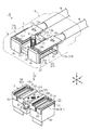
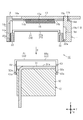
- FIG. 8 is a view showing a state before assembly of the first connector and the second connector in the first embodiment, and is a cross-sectional view showing a cross section along the YZ plane.
- FIG. 4 is a view showing a state before assembly of the first connector and the second connector in the first embodiment, and is a cross-sectional view showing a cross section along the XZ plane.
- the X axis in the XYZ axes represents the width direction of the electrical connection device
- the Y axis represents the depth direction of the electrical connection device orthogonal to the X axis
- the Z axis represents electrical connection orthogonal to the XY plane. It represents the height direction of the device.
- an electrical connection device 10 of the present embodiment is used, for example, at a connection site in a wire harness for a high-voltage power supply of a vehicle, and includes a first connector 11 and a second connector 12 that are assembled together. ing.
- the assembly direction of the first connector 11 with respect to the second connector 12 is indicated by an arrow D (hereinafter referred to as the assembly direction D).
- the assembly direction D indicates the relative assembly direction of the first connector 11 with respect to the second connector 12, and does not limit the second connector 12 as the fixed side.
- the second connector 12 may be assembled toward the first connector 11.
- the planes (opposing surface 13a and contact surface 31a) of the first terminal 13 of the first connector 11 and the second terminal 31 of the second connector 12 are arranged to face each other.
- a planar connection structure is provided in which the first and second terminals 13 and 31 are electrically connected via an oblique coil spring 15 as an elastic conductive member provided between the planes.
- the first connector 11 includes a pair of first terminals 13 connected to a pair of electric wires W, and a holding member 14 provided corresponding to each of the first terminals 13. And an oblique coil spring 15 as an elastic conducting member held by each holding member 14 and a first movable protection member 16 for preventing contact with the oblique coil spring 15 and the first terminal 13.
- the first connector 11 includes a first compression coil spring 17 as a biasing member that biases the first movable protection member 16.
- the first terminal 13, the holding member 14, the oblique coil spring 15, the first movable protection member 16, and the first compression coil spring 17 are a housing 18 that opens on the front side in the assembly direction D toward the second connector 12 (see FIG. 1). ).
- the assembly direction D is a direction along the height direction (Z-axis direction) of the electrical connecting device 10.
- the pair of electric wires W is a high-voltage electric wire, one is a positive side and the other is a negative side. Each electric wire W is drawn out from the proximal end side in the depth direction (Y-axis direction) of the housing 18. Further, in the first connector 11 (and a second connector 12 described later), the configurations on the plus side and the minus side arranged in the width direction (X-axis direction) are symmetrical with each other.
- FIG. 3 shows a cross-sectional view taken along line 3-3 in FIG. Further, the housing 18 is not shown in the drawings after FIG.
- the first terminal 13 has a plate shape and is arranged in a manner orthogonal to the height direction (Z-axis direction).
- the first terminal 13 has a long rectangular shape in the depth direction (Y-axis direction) in plan view (viewed in the Z-axis direction).
- the first terminals 13 are arranged in parallel in the width direction (X-axis direction) at the same position in the height direction.
- the oblique coil spring 15 has a coil shape in which a conductive wire is wound a plurality of times. Unlike the general coil spring, the oblique coil spring 15 is a coil spring wound so that the winding surface of each coil constituting the coil spring is inclined with respect to the coil axis. When a load is applied from the direction perpendicular to the axis, the inclined coil spring 15 falls into a state in which each winding surface is further inclined with respect to the coil axis, and is deformed so that the dimension in the direction perpendicular to the axis is reduced. The oblique coil spring 15 has a non-linear region in which the spring load does not change much even if the displacement amount in the direction perpendicular to the axis is changed.
- three oblique coil springs 15 are provided corresponding to each of the first terminals 13.
- the oblique coil spring 15 is provided in a mode of contacting with the facing surface 13 a that is a plate surface on the front side in the assembly direction D of the first terminal 13.
- the diagonal coil spring 15 is provided such that its longitudinal direction (coil axis direction) is along the Y-axis direction, and three diagonal coil springs 15 are arranged in the X-axis direction corresponding to each first terminal 13. Is provided.
- Each holding member 14 is made of a resin material.
- Each holding member 14 includes a frame portion 14 a provided on the front side in the assembly direction D with respect to the first terminal 13.
- the frame portion 14 a is provided with holding pieces 14 b that are respectively inserted in both longitudinal ends of the oblique coil spring 15 and hold the oblique coil spring 15.
- Two holding pieces 14b are provided for each oblique coil spring 15.
- Each holding member 14 includes an extension wall 14c extending in the assembly direction D from the tip end portion in the Y-axis direction (the end portion on the opposite side to the side from which the electric wire W is drawn) in the frame portion 14a. Yes.
- the extending wall 14c has a substantially plate shape orthogonal to the Y-axis direction.
- the first connector 11 of the present embodiment includes a resin fixing member 19 for fixing the first terminals 13 and the holding members 14 to the housing 18.
- the fixing member 19 includes a pair of sandwiching portions 19a disposed on the front side in the assembly direction D of the base end portion (the end portion on the electric wire W side) of the first terminal 13 and the holding member 14 in the Y-axis direction. And a fixing portion 19b formed so as to connect the holding portions 19a to each other.
- Each clamping part 19a is opposed to the extending wall 14c of each holding member 14 in the Y-axis direction.
- Each clamping part 19a is provided with a protruding part 19c that protrudes rearward in the assembly direction D.
- the protruding portion 19c is fitted in fitting holes 13b and 14d (see FIG. 3 and the like) formed in the first terminal 13 and the frame portion 14a, respectively. Then, by fixing the fixing portion 19b to the housing 18 by screwing or the like, the first terminal 13 and the frame portion 14a are held in the height direction (Z-axis direction) by the holding portion 19a and the housing 18. It has become so.
- the first movable protection member 16 is made of a resin material.
- the first movable protection member 16 is held movably in the height direction by the extending wall 14 c of each holding member 14 and each clamping portion 19 a of the fixing member 19.
- the first movable protection member 16 has a pair of protection member main body portions 21 respectively corresponding to the pair of first terminals 13.
- Each protection member main body portion 21 is formed with a pair of side wall portions 22 facing each other in the Y-axis direction and a protection portion 23 straddling the pair of side wall portions 22.
- the protection part 23 is provided so as to cover the front side (lower side in the figure) in the assembly direction D with respect to the facing surface 13 a of the first terminal 13.
- the protection part 23 has the slit-shaped insertion port 24 extended in a Y-axis direction as many as the diagonal coil spring 15 (three in this embodiment). Each insertion opening 24 faces each oblique coil spring 15 in the Z-axis direction.
- the protection part 23 has an extending part 23 a that extends in the Y-axis direction on both sides in the width direction (X-axis direction) of each insertion opening 24. Each extending portion 23 a is provided across the pair of side wall portions 22.
- each extending portion 23a is configured to enter both sides in the X-axis direction of each oblique coil spring 15 in a state where the first movable protection member 16 is in a retracted position to be described later (see FIG. 6).
- each extension part 23a of this embodiment has comprised the plate shape orthogonal to a height direction.
- one of the pair of side wall portions 22 of the protection member main body portion 21 is disposed inside the extending wall 14 c of the holding member 14 in the Y axis direction, and the other is the holding portion of the fixing member 19. It is arranged inside 19a in the Y-axis direction.
- a locking portion 22 a that protrudes outward in the Y-axis direction is formed.
- the locking portion 22 a of the one side wall portion 22 enters a guide groove 14 e formed along the height direction on the inner surface of the extending wall 14 c of the holding member 14.
- the locking portion 22a of the other side wall portion 22 enters a guide groove 19d formed along the height direction on the inner surface of the holding portion 19a of the fixing member 19.
- Each locking portion 22a is formed so as to be elastically deformable on the inner side in the Y-axis direction when the first movable protection member 16 is assembled.
- the first movable protection member 16 is formed with an intermediate portion 25 positioned between the pair of protection member main body portions 21.
- the intermediate portion 25 is formed with a spring accommodating portion 25a in which one end portion of the first compression coil spring 17 is accommodated (see FIG. 4).
- the first compression coil spring 17 is arranged so that its coil axis is along the height direction, and is configured to urge the first movable protection member 16 forward in the assembly direction D.
- one end of the first compression coil spring 17 in the coil axial direction is in contact with the spring accommodating portion 25a and the other end is in contact with the housing 18, and the spring accommodating portion 25a is the first to the front side in the assembly direction D. 1
- the biasing force of the compression coil spring 17 is received.
- a through hole 25b through which a bolt B (see FIG. 1) for fixing a shield cover (not shown) constituting the housing 18 is formed is formed in the spring accommodating portion 25a of the intermediate portion 25.
- the first compression coil spring 17 is extrapolated to the bolt B, and the first compression coil spring 17 and the bolt B are disposed between the pair of first terminals 13.
- a shaft insertion hole 25c through which a shaft portion (not shown) extending along the Z-axis direction from the housing 18 side is inserted is formed around the spring accommodating portion 25a in the intermediate portion 25 (see FIG. 2).
- the housing 18 is formed with a cylindrical bolt insertion collar (not shown) through which the bolt B is inserted. The bolt insertion collar is inserted into the first compression coil spring 17 to be inserted into the first compression coil spring 17. It functions as a fixed shaft that holds
- the first movable protection member 16 is configured to be movable between a protection position and a retracted position.
- 3 and 4 are views showing a state before the first connector 11 is assembled to the second connector 12, and showing a state in which the first movable protection member 16 is in the protected position.
- the protection part 23 of the first movable protection member 16 is located in front of the oblique coil spring 15 in the assembly direction D. Etc. are prevented from coming into contact with the facing surface 13a of the first terminal 13.
- each locking portion 22a of the protection member main body portion 21 is locked with one end portion in the height direction of each guide groove 14e, 19d (see FIG. 3).
- biased by the 1st compression coil spring 17 at the assembly direction D is hold
- the retracted position of the first movable protection member 16 is a position moved from the protection position to the first terminal 13 side (upper side in the figure) in the Z-axis direction (see FIG. 5 and the like).
- the second connector 12 is made of a pair of second terminals 31 arranged in parallel in the width direction (X-axis direction) and a resin-made holding each second terminal 31.
- a base member 32, a second movable protection member 33 assembled to the base member 32, and a second compression coil spring 34 as a biasing member that biases the second movable protection member 33 are provided.
- the configurations on the plus side and the minus side arranged in the width direction (X-axis direction) are symmetrical with each other.
- the second compression coil spring 34 is disposed at the center position in the width direction (X-axis direction) of the second connector 12 and between the pair of second terminals 31.
- Each of the second terminals 31 has a plate shape and is arranged in a manner perpendicular to the height direction (Z-axis direction).
- the surface on the upper side in the height direction (on the side opposite to the base member) of each second terminal 31 is a contact surface 31a with the first connector 11 side.
- each second terminal 31 of the present embodiment has one end in the Y-axis direction bent at a substantially right angle.
- the second movable protection member 33 is made of a resin material.
- the second movable protection member 33 includes a pair of protection member main body portions 41 respectively corresponding to the pair of second terminals 31, and an intermediate portion 42 positioned between the pair of protection member main body portions 41.
- Each protection member main body portion 41 is formed with a pair of side wall portions 43 facing each other in the Y-axis direction and a protection portion 44 straddling the pair of side wall portions 43.
- the protection part 44 is provided so as to cover the side (the upper side in the drawing) toward the first connector 11 with respect to the contact surface 31 a of the second terminal 31.
- the protection part 44 has the slit-shaped insertion port 45 extended in a Y-axis direction.
- the insertion port 45 is provided corresponding to each insertion port 24 of the first movable protection member 16 (first connector 11).
- the number of insertion holes 45 of the second movable protection member 33 is the same as the number of insertion holes 24 of the first movable protection member 16, and the insertion holes 24 and 45 face each other in the height direction (Z-axis direction). It is configured.
- the protection part 44 has an extending part 44a extending in the Y-axis direction on both sides in the width direction (X-axis direction) of each insertion port 45.
- Each extending portion 44 a is provided across the pair of side wall portions 43.
- the extended portions 44 a of the second movable protective member 33 are in contact with each extended portion 23 a of the first movable protective member 16 in the height direction.
- each extending portion 44 a is configured to enter both sides of each oblique coil spring 15 in the X-axis direction.
- each extension part 44a of this embodiment has comprised the plate shape orthogonal to a height direction.
- the width dimension in the X-axis direction of each extending part 44a is set equal to the width dimension in the X-axis direction of each extending part 23a (first movable protection member 16) that abuts each other in the assembled state.
- each side wall 43 of the protection member main body portion 41 is opposed to both side surfaces of the base member 32 in the Y-axis direction.
- Each side wall 43 is formed with a long hole 43a extending in the height direction.
- Each elongated hole 43a has a locking portion 32a protruding from each side surface of the base member 32 in the Y-axis direction.
- Each side wall 43 is formed so as to be elastically deformable on the outer side in the Y-axis direction when the second movable protection member 33 is assembled.
- a spring accommodating portion 42 a in which one end portion of the second compression coil spring 34 is accommodated is formed in the intermediate portion 42 of the second movable protection member 33.
- the second compression coil spring 34 is arranged such that its coil axis is along the height direction.
- the second compression coil spring 34 has one end in the coil axial direction in contact with the spring accommodating portion 42a and the other end in contact with the spring accommodating portion 32b of the base member 32. Biasing is performed in a direction away from the two terminals 31 (upward in the figure).
- the first compression coil spring 17 and the second compression coil spring 34 are configured to be aligned with each other in the height direction (that is, arranged coaxially).
- a through-hole 42b through which the bolt B (see FIG. 1) is inserted in the assembled state of the first and second connectors 11 and 12 is formed in the spring accommodating portion 42a of the intermediate portion 42. Further, in the assembled state of the first and second connectors 11 and 12, the bolt B is inserted into the second compression coil spring 34.
- a pair of shaft insertion holes 42c through which a pair of shaft portions 32c extending in the height direction from the base member 32 are inserted around the spring accommodating portion 42a in the intermediate portion 42, and the first A pair of shaft insertion holes 42d through which the shaft portion on the housing 18 side is inserted in the height direction in the assembled state of the second connectors 11 and 12 are formed.
- a pair of shaft portions 32c of the base member 32 is inserted around the spring accommodating portion 25a in the intermediate portion 25 of the first movable protection member 16 in the assembled state of the first and second connectors 11 and 12, respectively.
- a pair of shaft insertion holes 25d (only one is shown in FIG. 1) is formed.
- the second movable protection member 33 of the second connector 12 is configured to be movable between a protection position and a retracted position.
- 3 and 4 show a state in which the second movable protection member 33 is in the protection position.
- the protection portion 44 of the second movable protection member 33 (protection member main body portion 41) is spaced from the contact surface 31a of the second terminal 31 in the height direction (Z-axis direction) by a predetermined distance. It is separated. That is, the protection part 44 in the protection position covers the front side in the assembly direction toward the first connector 11 with respect to the contact surface 31a of the second terminal 31, and the protection part 44 includes external parts, fingers, and the like.
- locking part 32a of the base member 32 is latched with the one end part of the height direction of each long hole 43a of the protection member main-body part 41 (refer FIG. 3). Accordingly, the second movable protection member 33 urged by the second compression coil spring 34 in the direction away from the second terminal 31 (upward in the drawing) is held at the protection position.
- the retracted position of the second movable protection member 33 is a position moved from the protection position to the second terminal 31 side (downward in the figure) in the Z-axis direction (see FIG. 5 and the like).
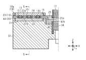
- FIGS. 5 and 6 are views showing a state in which the first connector 11 and the second connector 12 are assembled to each other.
- FIG. 5 shows a cross-sectional view taken along line 5-5 in FIG.
- the first and second movable protection members 16 and 33 are moved to the retracted positions, respectively.
- the opposing surface 13a of the first terminal 13 and the contact surface 31a of the second terminal 31 are parallel to each other, and are assembled so that the surfaces are close to each other.
- the insertion openings 24 and 45 in the protection portions 23 and 44 of the first and second movable protection members 16 and 33 face each other in the height direction, and the extension portions 23a and 44a of the protection portions 23 and 44 are in contact with each other. Abut against each other in the height direction.
- the first movable protection member 16 moves to its retracted position against the biasing force of the first compression coil spring 17, and the second movable protection member 33 resists the biasing force of the second compression coil spring 34. Move to its own retreat position.
- each diagonal coil spring 15 is in contact with both the facing surface 13 a of the first terminal 13 and the contact surface 31 a of the second terminal 31. Thereby, electrical continuity between the first terminal 13 and the second terminal 31 is achieved.
- the oblique coil spring 15 has a plurality of contacts with the first and second terminals 13 and 31 in the coil axis direction (Y-axis direction).
- the wire of the oblique coil spring 15 is changed as the distance between the first and second terminals 13 and 31 in the height direction becomes narrower (compressed in the height direction).
- the tilting angle becomes tight and the inclination angle becomes tight.
- the contact points of the oblique coil spring 15 move in the coil axis direction (so-called wiping is performed). Thereby, the foreign matter removal between the diagonal coil spring 15 and the 1st and 2nd terminals 13 and 31 is made.
- a test finger T that simulates the shape of a human finger that complies with safety standards is indicated by a two-dot chain line.
- the protection portion 23 of the first movable protection member 16 is located on the front side in the assembly direction D with respect to the oblique coil spring 15. In the protected position. Thereby, the protection part 23 prevents the test finger T from entering the first terminal 13.
- the protection portion 44 of the second movable protection member 33 is separated from the contact surface 31 a of the second terminal 31 by a predetermined distance in the height direction. In a protected position.
- the protection part 44 prevents the test finger T from entering the second terminal 31 side.
- the urging forces (spring forces) of the first and second compression coil springs 17 and 34 hold the first and second movable protection members 16 and 33 in the protected positions, respectively, and comply with safety standards. It is set to the magnitude of the force.
- the 1st connector 11 is provided in the aspect which contacts the 1st terminal 13 which has the flat opposing surface 13a which opposes the 2nd terminal 31 (mating terminal), and the opposing surface 13a, and this opposing surface 13a
- An oblique coil spring 15 that is capable of contacting the second terminal 31 while being elastically deformed in the orthogonal direction. Further, the first connector 11 moves between a protection position that covers the front side in the assembly direction D toward the second terminal 31 with respect to the facing surface 13a and a retracted position that is closer to the facing surface 13a than the protection position.
- the first movable protection member 16 having an insertion port 24 that is configured to be capable of being inserted into the oblique coil spring 15 at the retracted position and protruding forward in the assembly direction D is provided.
- the oblique coil spring 15 protruding from the insertion port 24 is configured to be able to contact the second terminal 31 in a state where the first movable protection member 16 is in the retracted position.
- the first movable protection member 16 when the first connector 11 is assembled to the second connector 12, the first movable protection member 16 is set to the retracted position, so that the first terminal 13 and the second terminal 31 are electrically connected. It becomes possible. And in the state which has not assembled
- a plurality of the oblique coil springs 15 as elastic conducting members are arranged in parallel along the opposing surface 13a.
- a plurality of insertion openings 24 of the first movable protection member 16 are provided corresponding to each of the plurality of oblique coil springs 15.
- the first movable protection member 16 can prevent external contact with the diagonal coil springs 15 and the first terminals 13.
- the oblique coil spring 15 as an elastic conducting member, foreign matter can be removed at the contact point between the oblique coil spring 15 and the first terminal 13 and at the contact point between the oblique coil spring 15 and the second terminal 31.
- the first connector 11 urges the first movable protection member 16 in the direction away from the facing surface 13a to hold the first movable protection member 16 in the protected position (the urging member). ).
- the 1st movable protection member 16 can be suitably hold
- the second connector 12 has a protection position that covers the front side of the assembly direction (opposite direction of the assembly direction D) toward the first connector 11 with respect to the contact surface 31a of the second terminal 31, and the protection position.
- a second movable protection member 33 configured to be movable between a retracted position approaching the contact surface 31a.
- the second movable protection member 33 has an insertion port 45 (second insertion port) that faces the insertion port 24 of the first movable protection member 16 in the assembly direction.
- the 1st terminal 13 and the 2nd terminal 31 are set by making the 1st and 2nd movable protection members 16 and 33 into a retracted position, respectively. It is possible to achieve an electrical connection with. And also in the 2nd connector 12, the contact from the outside with respect to the 2nd terminal 31 can be prevented by making the 2nd movable protection member 33 into a protection position in a non-assembly state.
- the second movable protection member 33 can prevent contact from the outside to the second terminal 31.
- the first connector 11 of the electrical connection device 50 of the present embodiment includes a fixed protection member 51 that is a fixed component, instead of the first movable protection member 16 of the first embodiment. .
- the fixed protective member 51 is made of a resin material.
- the fixed protective member 51 has protective walls 52 positioned on both sides of each oblique coil spring 15 in the width direction (X-axis direction).
- Each protective wall 52 is a wall that rises in the assembly direction D (Z-axis direction) with respect to the second connector 12, and is located on the front side in the assembly direction D with respect to the first terminal 13.
- the front end portion (lower end portion in FIG. 7) of each protective wall 52 in the assembly direction D is located on the front side (lower side in FIG. 7) in the assembly direction D with respect to the oblique coil spring 15.
- each protection wall 52 is set to the dimension which cannot touch the diagonal coil spring 15 with the said test finger (refer said 1st Embodiment) based on a safety standard.
- Each protective wall 52 is preferably formed linearly along the Y-axis direction, and the length in the Y-axis direction is preferably longer than the length of the oblique coil spring 15 in the coil axis direction.
- Each protective wall 52 of the fixed protective member 51 can be integrally formed with the first terminal 13 by insert molding or the like.
- the holding piece 14 b that holds the oblique coil spring 15 can be integrally formed with the fixed protection member 51.
- the second terminal 31 of the second connector 12 of the present embodiment is formed with a contact protrusion 61 that protrudes in the assembly direction toward the first connector 11 (the direction opposite to the assembly direction D).
- the contact protrusions 61 are provided in the same number (three in this embodiment) as the diagonal coil springs 15 and the insertion openings 45 of the second movable protection member 33.
- Each contact convex portion 61 faces each insertion port 45 on the front side in the assembly direction with respect to the first connector 11.
- the front end surface of each contact convex portion 61 toward the first connector 11 is a contact surface 61a that is in contact with each oblique coil spring 15, and the contact surface 61a is orthogonal to the height direction (Z-axis direction). It has a flat shape.
- the contact convex portion 61 is formed integrally with the second terminal 31.
- the present invention is not limited to this, and the contact convex portion 61 is a separate member from the second terminal 31 with respect to the second terminal 31. It is good also as a mode fixed.
- each extending portion 44 a of the protection portion 44 is in an assembly direction (with respect to the first connector 11) relative to the contact surface 61 a of each contact convex portion 61. It is located on the front side in the assembly direction). Thereby, it is prevented by each extended part 44a of the protection part 44 that an external component, a finger, etc. contact the contact surface 61a of each contact convex part 61.
- FIG. The interval in the width direction between the extending portions 44a (that is, the width direction dimension of the insertion port 45) is set equal to the interval in the width direction between the protective walls 52.
- the protective walls 52 of the first connector 11 are in contact with the corresponding extending portions 44a (second movable protective members 33) in the height direction. Touch. Thereby, as shown in FIG. 8, the second movable protection member 33 moves to the retracted position against the urging force of the second compression coil spring 34.
- each contact convex portion 61 (contact surface 61a) of the second terminal 31 passes through each insertion port 45 and the protection portion 44 (each extension of the second movable protection member 33). It protrudes forward (upward in the figure) from the portion 44a).
- Each contact convex portion 61 is inserted between each protective wall 52 of the first connector 11, and the contact surface 61 a of each contact convex portion 61 contacts the oblique coil spring 15.
- Each oblique coil spring 15 of the first connector 11 is elastically deformed (compressed) in the height direction between the facing surface 13a of the first terminal 13 and the contact surface 61a of each contact convex portion 61.
- the first and second terminals 13 and 31 are electrically connected to each other via the respective oblique coil springs 15.
- the first connector 11 includes a fixed protection member 51 disposed on the facing surface 13 a side of the first terminal 13.
- the second terminal 31 includes a contact convex portion 61 that protrudes forward in the assembly direction with respect to the first connector 11 and is inserted into the insertion opening 45 of the second movable protection member 33 in the retracted position. Then, in the assembled state of the first and second connectors 11, 12, the fixed protection member 51 comes into contact with the second movable protection member 33 to hold the second movable protection member 33 in the retracted position, and from the insertion port 45. The protruding contact convex portion 61 is brought into contact with the oblique coil spring 15.
- the first movable terminal 33 is set to the retracted position when the first connector 11 is assembled to the second connector 12. And the second terminal 31 can be electrically connected.
- the fixed protection member 51 prevents contact with the oblique coil spring 15 and the first terminal 13 from the outside in the first connector 11.
- the second movable protection member 33 set as the protection position prevents external contact with the second terminal 31 (contact convex portion 61).
- the fixed protective member 51 includes protective walls 52 disposed on both sides of each of the oblique coil springs 15 in the juxtaposed direction (X-axis direction).
- a plurality of contact protrusions 61 and insertion holes 45 are provided corresponding to each of the plurality of oblique coil springs 15.
- each said embodiment can be changed and implemented as follows.
- the above embodiments and the following modifications can be implemented in combination with each other within a technically consistent range.
- the fixed protection member has a configuration in which the protection portion 44 (each extending portion 44 a) of the first embodiment is fixed on the contact surface 31 a of the second terminal 31.
- the first movable protection member 16 is set to the retracted position, so that the first terminal 13 and the second terminal 31 are electrically connected. It becomes possible to plan.
- the contact from the outside with respect to the contact surface 31a of the 2nd terminal 31 is prevented by the fixed protection member.
- the configuration of the holding piece 14b that holds the diagonal coil spring 15 is an example, and can be changed to a configuration in which the holding piece 14b is inserted over the entire length of the diagonal coil spring 15, for example.
- the holding member 14 (holding piece 14b) may be omitted and the oblique coil spring 15 may be directly fixed to the facing surface 13a of the first terminal 13.
- the oblique coil spring 15 may be directly fixed to the facing surface 13a of the first terminal 13.
- the number of the oblique coil springs 15 in each of the above embodiments is an example, and may be configured with one, two, or four or more per one first terminal 13. Of course, it is desirable to appropriately change the numbers of the insertion holes 24, 45, the protective wall 52, the contact convex portion 61, and the like according to the number of the oblique coil springs 15.
- each of the oblique coil springs 15 is provided so that the coil axis is along the depth direction (Y-axis direction).
- the coil axis is along the width direction (X-axis direction). May be provided.
- the elastic conducting member interposed between the first and second terminals 13 and 31 in an elastically deformed state is configured by the oblique coil spring 15, but is not particularly limited thereto.
- the metal plate material having a plurality of cut-and-raised portions formed along the extending direction (Y-axis direction) of the insertion port 24 (or the protective wall 52) is fixed to the facing surface 13a of the first terminal 13,
- the cut and raised portions may be configured to elastically contact with the second terminals 31 (contact in a state of being elastically deformed in the height direction).
- first and second compression coil springs 17 and 34 are provided, but two or more may be provided. Similarly, in the second embodiment, two or more second compression coil springs 34 may be provided.
- the first compression coil spring 17 is arranged between the first terminal 13 on the plus side and the first terminal 13 on the minus side, but other than this, for example, the first movable protection member 16
- An urging member such as a compression coil spring may be provided near both ends in the width direction so that the first movable protection member 16 can be stably held at the protection position.
- the arrangement position of the second compression coil spring 34 of each of the above embodiments can be changed.
- the 1st and 2nd compression coil springs 17 and 34 will be given.
- Other biasing members may be used.
- the second compression coil spring 34 can be changed to another urging member.
- first and second movable protection members 16 and 33 are respectively held at the protected positions by a locking structure or the like.
- the urging members first and second compression coil springs 17, 34
- the second movable protection member 33 can be omitted.
- the configuration of the first and second terminals 13 and 31 in each of the above embodiments is an example, and can be appropriately changed according to the configuration.
- the technical idea which can be grasped from the above embodiments and modified examples will be described.
- the second connector includes a fixed protection member that is disposed to face the contact surface of the second terminal and prevents external contact with the second terminal;
- the fixed protective member of the second connector comes into contact with the first movable protective member (movable protective member of the first connector), and the first movable protective member is The electrical connection device is held at the retracted position, and the elastic conducting member is brought into contact with the contact surface of the second terminal through the insertion opening of the first movable protection member.
- the first movable protection member when the first movable protection member is set to the retracted position when the first connector is assembled to the second connector, the first terminal and the second terminal It is possible to achieve electrical connection. Then, in a state where the first connector and the second connector are not assembled to each other, the first movable protective member which is the protected position in the first connector is prevented from contacting the elastic conductive member and the first terminal from the outside. In the second connector, contact from the outside to the second terminal is prevented by the fixing protective member.
Landscapes
- Connector Housings Or Holding Contact Members (AREA)
- Details Of Connecting Devices For Male And Female Coupling (AREA)
Abstract
Selon la présente invention, un premier connecteur (11) comprend : une première borne (13) ayant une surface en regard plane (13a) qui fait face à une seconde borne (31), qui est une borne homologue ; et un ressort hélicoïdal oblique (15) qui est prévu pour entrer en contact avec la surface en regard (13a) et qui peut entrer en contact avec la seconde borne (31) tout en étant élastiquement déformé dans une direction perpendiculaire à la surface en regard (13a). De plus, le premier connecteur (11) comprend un premier élément de protection mobile (16) qui est configuré pour être mobile entre une position de protection, au niveau de laquelle le premier élément de protection mobile (16) recouvre une zone vers l'avant de la surface en regard (13a) dans une direction d'assemblage (D) allant vers la seconde borne (31), et une position en retrait plus proche de la surface en regard (13a) que la position de protection, et qui a des trous d'insertion (24) pour insérer le ressort hélicoïdal oblique (15) et amenant ainsi le ressort à faire saillie vers l'avant dans la direction d'assemblage D lorsque le premier élément de protection mobile (16) se trouve dans la position en retrait. De plus, la présente invention est configurée de telle sorte que le ressort hélicoïdal oblique (15) faisant saillie à partir des trous d'insertion (24) peut entrer en contact avec la seconde borne (31) lorsque le premier élément de protection mobile (16) se trouve dans la position en retrait.
Priority Applications (3)
| Application Number | Priority Date | Filing Date | Title |
|---|---|---|---|
| CN201980013980.XA CN111742449B (zh) | 2018-03-07 | 2019-02-21 | 连接器及电连接装置 |
| DE112019001183.9T DE112019001183B4 (de) | 2018-03-07 | 2019-02-21 | Verbinder und elektrische Verbindungsvorrichtung |
| US16/977,031 US11088485B2 (en) | 2018-03-07 | 2019-02-21 | Connector and electrical connection device |
Applications Claiming Priority (2)
| Application Number | Priority Date | Filing Date | Title |
|---|---|---|---|
| JP2018-040948 | 2018-03-07 | ||
| JP2018040948A JP6897608B2 (ja) | 2018-03-07 | 2018-03-07 | コネクタ及び電気接続装置 |
Publications (1)
| Publication Number | Publication Date |
|---|---|
| WO2019171970A1 true WO2019171970A1 (fr) | 2019-09-12 |
Family
ID=67845715
Family Applications (1)
| Application Number | Title | Priority Date | Filing Date |
|---|---|---|---|
| PCT/JP2019/006531 Ceased WO2019171970A1 (fr) | 2018-03-07 | 2019-02-21 | Connecteur et dispositif de connexion électrique |
Country Status (5)
| Country | Link |
|---|---|
| US (1) | US11088485B2 (fr) |
| JP (1) | JP6897608B2 (fr) |
| CN (1) | CN111742449B (fr) |
| DE (1) | DE112019001183B4 (fr) |
| WO (1) | WO2019171970A1 (fr) |
Cited By (2)
| Publication number | Priority date | Publication date | Assignee | Title |
|---|---|---|---|---|
| CN115088139A (zh) * | 2020-02-21 | 2022-09-20 | 住友电装株式会社 | 端子单元以及连接器 |
| WO2025028295A1 (fr) * | 2023-08-01 | 2025-02-06 | 株式会社オートネットワーク技術研究所 | Connecteur et ensemble connecteur |
Families Citing this family (5)
| Publication number | Priority date | Publication date | Assignee | Title |
|---|---|---|---|---|
| JP7367402B2 (ja) | 2019-09-03 | 2023-10-24 | 株式会社リコー | 印刷装置、接触部材、及び乾燥装置 |
| JP7370684B2 (ja) * | 2021-10-20 | 2023-10-30 | 矢崎総業株式会社 | コネクタ |
| CN114243395B (zh) * | 2021-12-31 | 2024-03-12 | 上海鑫悉科技有限公司 | 一种分段式新能源充电插座回路及其控制方法 |
| CN117080824B (zh) * | 2023-10-18 | 2024-01-09 | 成都速易联芯科技有限公司 | 一种带有高速差分的高速连接器及其使用方法 |
| DE102024115010A1 (de) | 2024-05-29 | 2025-12-04 | Dr. Ing. H.C. F. Porsche Aktiengesellschaft | Hochvolt-Stecker mit bewegbar gelagertem Berührschutz |
Citations (12)
| Publication number | Priority date | Publication date | Assignee | Title |
|---|---|---|---|---|
| JPH02148573U (fr) * | 1989-05-19 | 1990-12-18 | ||
| JPH0533477U (ja) * | 1991-10-07 | 1993-04-30 | 日本電気株式会社 | プリント基板接続用コネクタ構造 |
| JPH06290826A (ja) * | 1993-03-31 | 1994-10-18 | Sumitomo Wiring Syst Ltd | コネクタ |
| JP2001110509A (ja) * | 1999-10-01 | 2001-04-20 | Mitsubishi Motors Corp | コンタクトコネクタ |
| JP2017091835A (ja) * | 2015-11-11 | 2017-05-25 | 株式会社オートネットワーク技術研究所 | 端子金具、コネクタ |
| JP2017112031A (ja) * | 2015-12-18 | 2017-06-22 | 株式会社オートネットワーク技術研究所 | コネクタ |
| JP2017111993A (ja) * | 2015-12-17 | 2017-06-22 | 株式会社オートネットワーク技術研究所 | 端子金具及びコネクタ |
| JP2017117622A (ja) * | 2015-12-24 | 2017-06-29 | 株式会社オートネットワーク技術研究所 | 端子金具及びコネクタ |
| JP2018010826A (ja) * | 2016-07-15 | 2018-01-18 | 株式会社オートネットワーク技術研究所 | 端子 |
| JP2018106819A (ja) * | 2016-12-22 | 2018-07-05 | 株式会社オートネットワーク技術研究所 | コネクタ |
| JP2018116824A (ja) * | 2017-01-18 | 2018-07-26 | 株式会社オートネットワーク技術研究所 | 端子モジュール |
| JP2019003759A (ja) * | 2017-06-13 | 2019-01-10 | 株式会社オートネットワーク技術研究所 | 大電流用端子およびコネクタ |
Family Cites Families (9)
| Publication number | Priority date | Publication date | Assignee | Title |
|---|---|---|---|---|
| US5466164A (en) | 1993-03-09 | 1995-11-14 | Sumitomo Wiring Systems, Ltd. | Connector having a protective hood |
| CN2838103Y (zh) * | 2005-10-13 | 2006-11-15 | 实盈股份有限公司 | 具端子定位效果的处理器插座 |
| JP4919036B2 (ja) | 2007-01-30 | 2012-04-18 | アイシン精機株式会社 | 移動物体認識装置 |
| US7736202B1 (en) * | 2009-01-14 | 2010-06-15 | Gm Global Technology Operations, Inc. | Contact assembly for attachment to an electronics module |
| JP5589239B2 (ja) * | 2009-11-27 | 2014-09-17 | 住友化学株式会社 | 担持酸化ルテニウムの製造方法および塩素の製造方法 |
| US9466915B2 (en) * | 2011-10-03 | 2016-10-11 | Bal Seal Engineering, Inc. | In-line connectors and related methods |
| US10263368B2 (en) * | 2013-06-25 | 2019-04-16 | Bal Seal Engineering, Inc. | Electrical contacts with electrically conductive springs |
| CN203521699U (zh) * | 2013-07-30 | 2014-04-02 | 上海电巴新能源科技有限公司 | 一种可降低接触电阻的电连接结构 |
| CN104283055B (zh) * | 2014-11-04 | 2016-07-06 | 蔡晓红 | 一种滑动安全接口 |
-
2018
- 2018-03-07 JP JP2018040948A patent/JP6897608B2/ja active Active
-
2019
- 2019-02-21 WO PCT/JP2019/006531 patent/WO2019171970A1/fr not_active Ceased
- 2019-02-21 US US16/977,031 patent/US11088485B2/en active Active
- 2019-02-21 DE DE112019001183.9T patent/DE112019001183B4/de active Active
- 2019-02-21 CN CN201980013980.XA patent/CN111742449B/zh active Active
Patent Citations (12)
| Publication number | Priority date | Publication date | Assignee | Title |
|---|---|---|---|---|
| JPH02148573U (fr) * | 1989-05-19 | 1990-12-18 | ||
| JPH0533477U (ja) * | 1991-10-07 | 1993-04-30 | 日本電気株式会社 | プリント基板接続用コネクタ構造 |
| JPH06290826A (ja) * | 1993-03-31 | 1994-10-18 | Sumitomo Wiring Syst Ltd | コネクタ |
| JP2001110509A (ja) * | 1999-10-01 | 2001-04-20 | Mitsubishi Motors Corp | コンタクトコネクタ |
| JP2017091835A (ja) * | 2015-11-11 | 2017-05-25 | 株式会社オートネットワーク技術研究所 | 端子金具、コネクタ |
| JP2017111993A (ja) * | 2015-12-17 | 2017-06-22 | 株式会社オートネットワーク技術研究所 | 端子金具及びコネクタ |
| JP2017112031A (ja) * | 2015-12-18 | 2017-06-22 | 株式会社オートネットワーク技術研究所 | コネクタ |
| JP2017117622A (ja) * | 2015-12-24 | 2017-06-29 | 株式会社オートネットワーク技術研究所 | 端子金具及びコネクタ |
| JP2018010826A (ja) * | 2016-07-15 | 2018-01-18 | 株式会社オートネットワーク技術研究所 | 端子 |
| JP2018106819A (ja) * | 2016-12-22 | 2018-07-05 | 株式会社オートネットワーク技術研究所 | コネクタ |
| JP2018116824A (ja) * | 2017-01-18 | 2018-07-26 | 株式会社オートネットワーク技術研究所 | 端子モジュール |
| JP2019003759A (ja) * | 2017-06-13 | 2019-01-10 | 株式会社オートネットワーク技術研究所 | 大電流用端子およびコネクタ |
Cited By (2)
| Publication number | Priority date | Publication date | Assignee | Title |
|---|---|---|---|---|
| CN115088139A (zh) * | 2020-02-21 | 2022-09-20 | 住友电装株式会社 | 端子单元以及连接器 |
| WO2025028295A1 (fr) * | 2023-08-01 | 2025-02-06 | 株式会社オートネットワーク技術研究所 | Connecteur et ensemble connecteur |
Also Published As
| Publication number | Publication date |
|---|---|
| DE112019001183B4 (de) | 2025-02-27 |
| JP6897608B2 (ja) | 2021-06-30 |
| DE112019001183T5 (de) | 2020-12-17 |
| CN111742449A (zh) | 2020-10-02 |
| JP2019160416A (ja) | 2019-09-19 |
| CN111742449B (zh) | 2021-09-17 |
| US11088485B2 (en) | 2021-08-10 |
| US20210044049A1 (en) | 2021-02-11 |
Similar Documents
| Publication | Publication Date | Title |
|---|---|---|
| JP2019160416A (ja) | コネクタ及び電気接続装置 | |
| CN110635308B (zh) | 固定金属件、电连接器以及电连接器装置 | |
| KR100433704B1 (ko) | 접촉 신뢰성을 갖는 커넥터 | |
| US9147971B2 (en) | Electrical connector and squib connection device | |
| KR102538789B1 (ko) | 다접점 커넥터 | |
| CN103730751B (zh) | 防触指连接器 | |
| JP6325505B2 (ja) | コネクタ | |
| US10622743B2 (en) | Terminal module with a conductive obliquely wound coil spring held against an electrical contact member and connector having such a terminal module | |
| KR20140067903A (ko) | 부품 모듈과 상대측 커넥터 및 부품 모듈과 상대측 커넥터와의 접속 구조 | |
| US20170288339A1 (en) | Power source connector device | |
| CN111903006A (zh) | 连接器 | |
| US11394153B2 (en) | Connector and terminal | |
| JP5999440B2 (ja) | コネクタ | |
| CN119605036A (zh) | 阴端子 | |
| JP7264864B2 (ja) | コネクタ | |
| JP2019102285A (ja) | 可動コネクタ | |
| WO2011077264A2 (fr) | Connecteur flottant et système | |
| US11005208B2 (en) | Connector and wire harness | |
| JP2015022968A (ja) | コネクタ | |
| CN114665320B (zh) | 直角连接器和连接器组件 | |
| US12500367B2 (en) | Terminal unit with improved protection | |
| CN114600321B (zh) | 连接器 | |
| CN213340987U (zh) | 插头电连接器与插座电连接器 | |
| WO2012096407A1 (fr) | Boîtier de protection d'une prise | |
| CN110635257B (zh) | 电连接器及电连接器的制造方法 |
Legal Events
| Date | Code | Title | Description |
|---|---|---|---|
| 121 | Ep: the epo has been informed by wipo that ep was designated in this application |
Ref document number: 19765042 Country of ref document: EP Kind code of ref document: A1 |
|
| 122 | Ep: pct application non-entry in european phase |
Ref document number: 19765042 Country of ref document: EP Kind code of ref document: A1 |
|
| WWG | Wipo information: grant in national office |
Ref document number: 112019001183 Country of ref document: DE |