WO2019172036A1 - 密封装置および密封構造 - Google Patents
密封装置および密封構造 Download PDFInfo
- Publication number
- WO2019172036A1 WO2019172036A1 PCT/JP2019/007515 JP2019007515W WO2019172036A1 WO 2019172036 A1 WO2019172036 A1 WO 2019172036A1 JP 2019007515 W JP2019007515 W JP 2019007515W WO 2019172036 A1 WO2019172036 A1 WO 2019172036A1
- Authority
- WO
- WIPO (PCT)
- Prior art keywords
- water discharge
- seal member
- sealing device
- flange
- water
- Prior art date
- Legal status (The legal status is an assumption and is not a legal conclusion. Google has not performed a legal analysis and makes no representation as to the accuracy of the status listed.)
- Ceased
Links
Images


Classifications
-
- F—MECHANICAL ENGINEERING; LIGHTING; HEATING; WEAPONS; BLASTING
- F16—ENGINEERING ELEMENTS AND UNITS; GENERAL MEASURES FOR PRODUCING AND MAINTAINING EFFECTIVE FUNCTIONING OF MACHINES OR INSTALLATIONS; THERMAL INSULATION IN GENERAL
- F16C—SHAFTS; FLEXIBLE SHAFTS; ELEMENTS OR CRANKSHAFT MECHANISMS; ROTARY BODIES OTHER THAN GEARING ELEMENTS; BEARINGS
- F16C33/00—Parts of bearings; Special methods for making bearings or parts thereof
- F16C33/72—Sealings
- F16C33/76—Sealings of ball or roller bearings
- F16C33/80—Labyrinth sealings
- F16C33/805—Labyrinth sealings in addition to other sealings, e.g. dirt guards to protect sealings with sealing lips
-
- F—MECHANICAL ENGINEERING; LIGHTING; HEATING; WEAPONS; BLASTING
- F16—ENGINEERING ELEMENTS AND UNITS; GENERAL MEASURES FOR PRODUCING AND MAINTAINING EFFECTIVE FUNCTIONING OF MACHINES OR INSTALLATIONS; THERMAL INSULATION IN GENERAL
- F16C—SHAFTS; FLEXIBLE SHAFTS; ELEMENTS OR CRANKSHAFT MECHANISMS; ROTARY BODIES OTHER THAN GEARING ELEMENTS; BEARINGS
- F16C33/00—Parts of bearings; Special methods for making bearings or parts thereof
- F16C33/72—Sealings
- F16C33/76—Sealings of ball or roller bearings
- F16C33/78—Sealings of ball or roller bearings with a diaphragm, disc, or ring, with or without resilient members
- F16C33/7816—Details of the sealing or parts thereof, e.g. geometry, material
- F16C33/782—Details of the sealing or parts thereof, e.g. geometry, material of the sealing region
- F16C33/7823—Details of the sealing or parts thereof, e.g. geometry, material of the sealing region of sealing lips
-
- F—MECHANICAL ENGINEERING; LIGHTING; HEATING; WEAPONS; BLASTING
- F16—ENGINEERING ELEMENTS AND UNITS; GENERAL MEASURES FOR PRODUCING AND MAINTAINING EFFECTIVE FUNCTIONING OF MACHINES OR INSTALLATIONS; THERMAL INSULATION IN GENERAL
- F16C—SHAFTS; FLEXIBLE SHAFTS; ELEMENTS OR CRANKSHAFT MECHANISMS; ROTARY BODIES OTHER THAN GEARING ELEMENTS; BEARINGS
- F16C19/00—Bearings with rolling contact, for exclusively rotary movement
- F16C19/02—Bearings with rolling contact, for exclusively rotary movement with bearing balls essentially of the same size in one or more circular rows
- F16C19/14—Bearings with rolling contact, for exclusively rotary movement with bearing balls essentially of the same size in one or more circular rows for both radial and axial load
- F16C19/16—Bearings with rolling contact, for exclusively rotary movement with bearing balls essentially of the same size in one or more circular rows for both radial and axial load with a single row of balls
-
- F—MECHANICAL ENGINEERING; LIGHTING; HEATING; WEAPONS; BLASTING
- F16—ENGINEERING ELEMENTS AND UNITS; GENERAL MEASURES FOR PRODUCING AND MAINTAINING EFFECTIVE FUNCTIONING OF MACHINES OR INSTALLATIONS; THERMAL INSULATION IN GENERAL
- F16C—SHAFTS; FLEXIBLE SHAFTS; ELEMENTS OR CRANKSHAFT MECHANISMS; ROTARY BODIES OTHER THAN GEARING ELEMENTS; BEARINGS
- F16C19/00—Bearings with rolling contact, for exclusively rotary movement
- F16C19/02—Bearings with rolling contact, for exclusively rotary movement with bearing balls essentially of the same size in one or more circular rows
- F16C19/14—Bearings with rolling contact, for exclusively rotary movement with bearing balls essentially of the same size in one or more circular rows for both radial and axial load
- F16C19/18—Bearings with rolling contact, for exclusively rotary movement with bearing balls essentially of the same size in one or more circular rows for both radial and axial load with two or more rows of balls
- F16C19/181—Bearings with rolling contact, for exclusively rotary movement with bearing balls essentially of the same size in one or more circular rows for both radial and axial load with two or more rows of balls with angular contact
- F16C19/183—Bearings with rolling contact, for exclusively rotary movement with bearing balls essentially of the same size in one or more circular rows for both radial and axial load with two or more rows of balls with angular contact with two rows at opposite angles
- F16C19/184—Bearings with rolling contact, for exclusively rotary movement with bearing balls essentially of the same size in one or more circular rows for both radial and axial load with two or more rows of balls with angular contact with two rows at opposite angles in O-arrangement
- F16C19/185—Bearings with rolling contact, for exclusively rotary movement with bearing balls essentially of the same size in one or more circular rows for both radial and axial load with two or more rows of balls with angular contact with two rows at opposite angles in O-arrangement with two raceways provided integrally on a part other than a race ring, e.g. a shaft or housing
-
- F—MECHANICAL ENGINEERING; LIGHTING; HEATING; WEAPONS; BLASTING
- F16—ENGINEERING ELEMENTS AND UNITS; GENERAL MEASURES FOR PRODUCING AND MAINTAINING EFFECTIVE FUNCTIONING OF MACHINES OR INSTALLATIONS; THERMAL INSULATION IN GENERAL
- F16C—SHAFTS; FLEXIBLE SHAFTS; ELEMENTS OR CRANKSHAFT MECHANISMS; ROTARY BODIES OTHER THAN GEARING ELEMENTS; BEARINGS
- F16C33/00—Parts of bearings; Special methods for making bearings or parts thereof
- F16C33/72—Sealings
- F16C33/76—Sealings of ball or roller bearings
- F16C33/78—Sealings of ball or roller bearings with a diaphragm, disc, or ring, with or without resilient members
- F16C33/7803—Sealings of ball or roller bearings with a diaphragm, disc, or ring, with or without resilient members suited for particular types of rolling bearings
- F16C33/7806—Sealings of ball or roller bearings with a diaphragm, disc, or ring, with or without resilient members suited for particular types of rolling bearings for spherical roller bearings
-
- F—MECHANICAL ENGINEERING; LIGHTING; HEATING; WEAPONS; BLASTING
- F16—ENGINEERING ELEMENTS AND UNITS; GENERAL MEASURES FOR PRODUCING AND MAINTAINING EFFECTIVE FUNCTIONING OF MACHINES OR INSTALLATIONS; THERMAL INSULATION IN GENERAL
- F16C—SHAFTS; FLEXIBLE SHAFTS; ELEMENTS OR CRANKSHAFT MECHANISMS; ROTARY BODIES OTHER THAN GEARING ELEMENTS; BEARINGS
- F16C33/00—Parts of bearings; Special methods for making bearings or parts thereof
- F16C33/72—Sealings
- F16C33/76—Sealings of ball or roller bearings
- F16C33/78—Sealings of ball or roller bearings with a diaphragm, disc, or ring, with or without resilient members
- F16C33/7816—Details of the sealing or parts thereof, e.g. geometry, material
- F16C33/782—Details of the sealing or parts thereof, e.g. geometry, material of the sealing region
- F16C33/7826—Details of the sealing or parts thereof, e.g. geometry, material of the sealing region of the opposing surface cooperating with the seal, e.g. a shoulder surface of a bearing ring
-
- F—MECHANICAL ENGINEERING; LIGHTING; HEATING; WEAPONS; BLASTING
- F16—ENGINEERING ELEMENTS AND UNITS; GENERAL MEASURES FOR PRODUCING AND MAINTAINING EFFECTIVE FUNCTIONING OF MACHINES OR INSTALLATIONS; THERMAL INSULATION IN GENERAL
- F16C—SHAFTS; FLEXIBLE SHAFTS; ELEMENTS OR CRANKSHAFT MECHANISMS; ROTARY BODIES OTHER THAN GEARING ELEMENTS; BEARINGS
- F16C33/00—Parts of bearings; Special methods for making bearings or parts thereof
- F16C33/72—Sealings
- F16C33/76—Sealings of ball or roller bearings
- F16C33/78—Sealings of ball or roller bearings with a diaphragm, disc, or ring, with or without resilient members
- F16C33/7869—Sealings of ball or roller bearings with a diaphragm, disc, or ring, with or without resilient members mounted with a cylindrical portion to the inner surface of the outer race and having a radial portion extending inward
- F16C33/7873—Sealings of ball or roller bearings with a diaphragm, disc, or ring, with or without resilient members mounted with a cylindrical portion to the inner surface of the outer race and having a radial portion extending inward with a single sealing ring of generally L-shaped cross-section
- F16C33/7876—Sealings of ball or roller bearings with a diaphragm, disc, or ring, with or without resilient members mounted with a cylindrical portion to the inner surface of the outer race and having a radial portion extending inward with a single sealing ring of generally L-shaped cross-section with sealing lips
-
- F—MECHANICAL ENGINEERING; LIGHTING; HEATING; WEAPONS; BLASTING
- F16—ENGINEERING ELEMENTS AND UNITS; GENERAL MEASURES FOR PRODUCING AND MAINTAINING EFFECTIVE FUNCTIONING OF MACHINES OR INSTALLATIONS; THERMAL INSULATION IN GENERAL
- F16C—SHAFTS; FLEXIBLE SHAFTS; ELEMENTS OR CRANKSHAFT MECHANISMS; ROTARY BODIES OTHER THAN GEARING ELEMENTS; BEARINGS
- F16C33/00—Parts of bearings; Special methods for making bearings or parts thereof
- F16C33/72—Sealings
- F16C33/76—Sealings of ball or roller bearings
- F16C33/78—Sealings of ball or roller bearings with a diaphragm, disc, or ring, with or without resilient members
- F16C33/7869—Sealings of ball or roller bearings with a diaphragm, disc, or ring, with or without resilient members mounted with a cylindrical portion to the inner surface of the outer race and having a radial portion extending inward
- F16C33/7879—Sealings of ball or roller bearings with a diaphragm, disc, or ring, with or without resilient members mounted with a cylindrical portion to the inner surface of the outer race and having a radial portion extending inward with a further sealing ring
- F16C33/7883—Sealings of ball or roller bearings with a diaphragm, disc, or ring, with or without resilient members mounted with a cylindrical portion to the inner surface of the outer race and having a radial portion extending inward with a further sealing ring mounted to the inner race and of generally L-shape, the two sealing rings defining a sealing with box-shaped cross-section
-
- F—MECHANICAL ENGINEERING; LIGHTING; HEATING; WEAPONS; BLASTING
- F16—ENGINEERING ELEMENTS AND UNITS; GENERAL MEASURES FOR PRODUCING AND MAINTAINING EFFECTIVE FUNCTIONING OF MACHINES OR INSTALLATIONS; THERMAL INSULATION IN GENERAL
- F16J—PISTONS; CYLINDERS; SEALINGS
- F16J15/00—Sealings
- F16J15/16—Sealings between relatively-moving surfaces
- F16J15/164—Sealings between relatively-moving surfaces the sealing action depending on movements; pressure difference, temperature or presence of leaking fluid
-
- F—MECHANICAL ENGINEERING; LIGHTING; HEATING; WEAPONS; BLASTING
- F16—ENGINEERING ELEMENTS AND UNITS; GENERAL MEASURES FOR PRODUCING AND MAINTAINING EFFECTIVE FUNCTIONING OF MACHINES OR INSTALLATIONS; THERMAL INSULATION IN GENERAL
- F16J—PISTONS; CYLINDERS; SEALINGS
- F16J15/00—Sealings
- F16J15/16—Sealings between relatively-moving surfaces
- F16J15/32—Sealings between relatively-moving surfaces with elastic sealings, e.g. O-rings
- F16J15/3204—Sealings between relatively-moving surfaces with elastic sealings, e.g. O-rings with at least one lip
- F16J15/3232—Sealings between relatively-moving surfaces with elastic sealings, e.g. O-rings with at least one lip having two or more lips
-
- F—MECHANICAL ENGINEERING; LIGHTING; HEATING; WEAPONS; BLASTING
- F16—ENGINEERING ELEMENTS AND UNITS; GENERAL MEASURES FOR PRODUCING AND MAINTAINING EFFECTIVE FUNCTIONING OF MACHINES OR INSTALLATIONS; THERMAL INSULATION IN GENERAL
- F16J—PISTONS; CYLINDERS; SEALINGS
- F16J15/00—Sealings
- F16J15/16—Sealings between relatively-moving surfaces
- F16J15/32—Sealings between relatively-moving surfaces with elastic sealings, e.g. O-rings
- F16J15/3244—Sealings between relatively-moving surfaces with elastic sealings, e.g. O-rings with hydrodynamic pumping action
-
- F—MECHANICAL ENGINEERING; LIGHTING; HEATING; WEAPONS; BLASTING
- F16—ENGINEERING ELEMENTS AND UNITS; GENERAL MEASURES FOR PRODUCING AND MAINTAINING EFFECTIVE FUNCTIONING OF MACHINES OR INSTALLATIONS; THERMAL INSULATION IN GENERAL
- F16J—PISTONS; CYLINDERS; SEALINGS
- F16J15/00—Sealings
- F16J15/16—Sealings between relatively-moving surfaces
- F16J15/32—Sealings between relatively-moving surfaces with elastic sealings, e.g. O-rings
- F16J15/3248—Sealings between relatively-moving surfaces with elastic sealings, e.g. O-rings provided with casings or supports
- F16J15/3252—Sealings between relatively-moving surfaces with elastic sealings, e.g. O-rings provided with casings or supports with rigid casings or supports
- F16J15/3256—Sealings between relatively-moving surfaces with elastic sealings, e.g. O-rings provided with casings or supports with rigid casings or supports comprising two casing or support elements, one attached to each surface, e.g. cartridge or cassette seals
- F16J15/3264—Sealings between relatively-moving surfaces with elastic sealings, e.g. O-rings provided with casings or supports with rigid casings or supports comprising two casing or support elements, one attached to each surface, e.g. cartridge or cassette seals the elements being separable from each other
-
- F—MECHANICAL ENGINEERING; LIGHTING; HEATING; WEAPONS; BLASTING
- F16—ENGINEERING ELEMENTS AND UNITS; GENERAL MEASURES FOR PRODUCING AND MAINTAINING EFFECTIVE FUNCTIONING OF MACHINES OR INSTALLATIONS; THERMAL INSULATION IN GENERAL
- F16J—PISTONS; CYLINDERS; SEALINGS
- F16J15/00—Sealings
- F16J15/16—Sealings between relatively-moving surfaces
- F16J15/32—Sealings between relatively-moving surfaces with elastic sealings, e.g. O-rings
- F16J15/3284—Sealings between relatively-moving surfaces with elastic sealings, e.g. O-rings characterised by their structure; Selection of materials
-
- F—MECHANICAL ENGINEERING; LIGHTING; HEATING; WEAPONS; BLASTING
- F16—ENGINEERING ELEMENTS AND UNITS; GENERAL MEASURES FOR PRODUCING AND MAINTAINING EFFECTIVE FUNCTIONING OF MACHINES OR INSTALLATIONS; THERMAL INSULATION IN GENERAL
- F16C—SHAFTS; FLEXIBLE SHAFTS; ELEMENTS OR CRANKSHAFT MECHANISMS; ROTARY BODIES OTHER THAN GEARING ELEMENTS; BEARINGS
- F16C19/00—Bearings with rolling contact, for exclusively rotary movement
- F16C19/02—Bearings with rolling contact, for exclusively rotary movement with bearing balls essentially of the same size in one or more circular rows
- F16C19/14—Bearings with rolling contact, for exclusively rotary movement with bearing balls essentially of the same size in one or more circular rows for both radial and axial load
- F16C19/18—Bearings with rolling contact, for exclusively rotary movement with bearing balls essentially of the same size in one or more circular rows for both radial and axial load with two or more rows of balls
- F16C19/181—Bearings with rolling contact, for exclusively rotary movement with bearing balls essentially of the same size in one or more circular rows for both radial and axial load with two or more rows of balls with angular contact
-
- F—MECHANICAL ENGINEERING; LIGHTING; HEATING; WEAPONS; BLASTING
- F16—ENGINEERING ELEMENTS AND UNITS; GENERAL MEASURES FOR PRODUCING AND MAINTAINING EFFECTIVE FUNCTIONING OF MACHINES OR INSTALLATIONS; THERMAL INSULATION IN GENERAL
- F16C—SHAFTS; FLEXIBLE SHAFTS; ELEMENTS OR CRANKSHAFT MECHANISMS; ROTARY BODIES OTHER THAN GEARING ELEMENTS; BEARINGS
- F16C2326/00—Articles relating to transporting
- F16C2326/01—Parts of vehicles in general
- F16C2326/02—Wheel hubs or castors
-
- F—MECHANICAL ENGINEERING; LIGHTING; HEATING; WEAPONS; BLASTING
- F16—ENGINEERING ELEMENTS AND UNITS; GENERAL MEASURES FOR PRODUCING AND MAINTAINING EFFECTIVE FUNCTIONING OF MACHINES OR INSTALLATIONS; THERMAL INSULATION IN GENERAL
- F16C—SHAFTS; FLEXIBLE SHAFTS; ELEMENTS OR CRANKSHAFT MECHANISMS; ROTARY BODIES OTHER THAN GEARING ELEMENTS; BEARINGS
- F16C33/00—Parts of bearings; Special methods for making bearings or parts thereof
- F16C33/72—Sealings
- F16C33/76—Sealings of ball or roller bearings
- F16C33/80—Labyrinth sealings
Definitions
- the present invention relates to a sealing device and a sealing structure.
- This sealing device for sealing the inside of a rolling bearing, there is one described in Patent Document 1.
- This sealing device includes an annular body fixed to an outer ring of a rolling bearing, a radial lip (grease lip) extending radially inward from the annular body, and two side lips (axial lips) extending laterally from the annular body.
- the radial lip is in contact with the outer peripheral surface of the inner ring of the bearing or the outer peripheral surface of the component fixed to the inner ring, and has a function of sealing lubricant (grease) inside the bearing, and the two side lips are flanges of the inner ring.
- has a function of sealing so that foreign matter such as water and dust does not enter the inside of the bearing from the outside.
- the present invention provides a sealing device and a sealing structure that have high water discharge performance and high protection performance against water to be sealed.
- a sealing device is a sealing device that is disposed between a relatively rotating inner member and an outer member, and seals a gap between the inner member and the outer member, A first seal member attached to the outer member and having an annular portion, the annular portion extending radially inward toward the inner member, and a flange portion attached to the inner member
- the flange portion extends radially outward, and includes a second seal member facing the annular portion of the first seal member, and at least one of the first seal member and the second seal member
- On one side a plurality of water discharge protrusions are supported, and the plurality of water discharge protrusions are spaces located between the annular portion of the first seal member and the flange portion of the second seal member.
- each water discharge projections, at least one of said inner member and said outer member having an inclined side surface intersecting at an acute angle to the rotational direction of rotation.
- water may enter the space between the annular portion of the first seal member and the flange portion of the second seal member.
- a plurality of water discharge protrusions protrude in the space, and each water discharge protrusion has an inclined side surface that intersects at an acute angle with respect to a rotation direction in which at least one of the inner member and the outer member rotates. Therefore, with relative rotation of the inner member and the outer member, the water in the space flows in the opposite direction along the inclined side surface and is quickly discharged from the space. For this reason, the sealing device has a high protection performance against water to be sealed. Further, since the plurality of water discharge protrusions protrude into the space between the annular portion of the first seal member and the flange portion of the second seal member, it is necessary to enlarge the sealing device for the water discharge protrusion. Absent.
- a sealing structure includes a cylindrical portion, an inner member having a flange that extends radially outward from the cylindrical portion, an outer member that rotates relative to the inner member, and the outer member.
- An annular portion, and the annular portion extends radially inward toward the cylindrical portion of the inner member and includes a seal member facing the flange of the inner member,
- a plurality of water discharge protrusions are supported on at least one of the inner member and the seal member, and the plurality of water discharge protrusions are located between the annular portion of the seal member and the flange of the inner member. Projecting into the space and arranged in the circumferential direction, each water discharge projection has an inclined side surface that intersects at an acute angle with respect to the rotational direction in which at least one of the inner member and the outer member rotates.
- each water discharge protrusion has an inclined side surface that intersects at an acute angle with respect to a rotation direction in which at least one of the inner member and the outer member rotates. Therefore, with relative rotation of the inner member and the outer member, the water in the space flows in the opposite direction along the inclined side surface and is quickly discharged from the space. For this reason, the sealing structure has a high protection performance against water to be sealed. Further, since the plurality of water discharge protrusions protrude into the space between the annular portion of the seal member and the flange of the inner member, it is not necessary to increase the size of the sealing structure for the water discharge protrusion.
- FIG. 12 is a partial cross-sectional view of a variation of the sealing device of FIG. 11. It is a fragmentary sectional view of the sealing device concerning the further another modification of a 1st embodiment. It is a fragmentary perspective view which fractures
- FIG. 20 is a cross-sectional view taken along line XX-XX in FIG. 19. It is a figure which shows the advantage at the time of rotation of the 2nd sealing member of the sealing device of FIG. It is a figure which shows the advantage at the time of the rotation stop of the 2nd sealing member of the sealing device of FIG. It is sectional drawing of the sealing device which concerns on the modification of the modification of FIG. It is sectional drawing of the sealing device which concerns on the other modification of the modification of FIG. It is a fragmentary perspective view which fractures
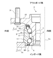
- FIG. 1 shows a hub bearing for an automobile, which is an example of a rolling bearing in which a sealing device according to an embodiment of the present invention is used.
- the application of the present invention is not limited to the hub bearing, and the present invention can also be applied to other rolling bearings.
- the hub bearing is a ball bearing.
- the application of the present invention is not limited to the ball bearing, and other rolling bearings such as roller bearings and needle bearings having other types of rolling elements.
- the present invention is applicable.
- the present invention is also applicable to rolling bearings used in machines other than automobiles.
- the hub bearing 1 is disposed outside a hub (inner member) 4 having a hole 2 into which a spindle (not shown) is inserted, an inner ring (inner member) 6 attached to the hub 4, and an outer side thereof.
- An outer ring (outer member) 8 a plurality of balls 10 arranged in a row between the hub 4 and the outer ring 8, a plurality of balls 12 arranged in a row between the inner ring 6 and the outer ring 8, and And a plurality of cages 14 and 15 for holding the balls in place.
- the common central axis Ax of the spindle and hub bearing 1 extends in the vertical direction in FIG. In FIG. 1, only the left portion with respect to the central axis Ax is shown.
- the upper side of FIG. 1 is the outer side (outboard side) where the wheels of the automobile are arranged, and the lower side is the inner side (inboard side) where the differential gears are arranged.
- the outer side and the inner side shown in FIG. 1 mean the outer side and the inner side in the radial direction, respectively.
- the outer ring 8 of the hub bearing 1 is fixed to the hub knuckle 16.
- the hub 4 has an outboard side flange 18 projecting outward in the radial direction from the outer ring 8.
- a wheel can be attached to the outboard flange 18 by a hub bolt 19.
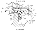
- a sealing device 20 that seals the gap between the outer ring 8 and the hub 4 is disposed near the end of the outer ring 8 on the outboard side, and inside the end of the outer ring 8 on the inboard side.
- a sealing device 21 that seals the gap between the outer ring 8 and the inner ring 6 is disposed. The action of the sealing devices 20 and 21 prevents the grease, that is, the lubricant from flowing out from the inside of the hub bearing 1 and prevents foreign matter (water (including muddy water or salt water) from entering the inside of the hub bearing 1 from the outside. And dust) are prevented.
- an arrow F indicates an example of the direction of foreign matter flow from the outside.
- the sealing device 20 is disposed between the rotating hub 4 of the hub bearing 1 and the cylindrical end portion 8A on the outboard side of the fixed outer ring 8, and seals the gap between the hub 4 and the outer ring 8. To do.
- the sealing device 21 is disposed between the rotating inner ring 6 of the hub bearing 1 and the end 8B on the inboard side of the fixed outer ring 8, and seals the gap between the inner ring 6 and the outer ring 8.
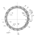
- the sealing device 21 is disposed in a gap between the end 8 ⁇ / b> B on the inboard side of the outer ring 8 of the hub bearing 1 and the inner ring 6 of the hub bearing 1.
- the sealing device 21 has an annular shape, only the left side portion is shown in FIG.
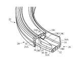
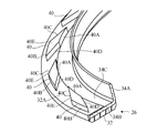
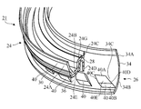
- FIG. 3 is a partial perspective view showing a part of the sealing device 21 in a broken state.
- FIG. 4 is a partial perspective view showing a part of the first seal member 24 that is a part of the sealing device 21 in a cutaway manner.
- FIG. 5 is a partial perspective view showing a part of the second seal member 26, which is a part of the sealing device 21, in a cutaway manner.
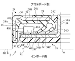
- the sealing device 22 has a composite structure including a first seal member 24 and a second seal member 26.
- the first seal member 24 is a fixed seal member that is attached to the outer ring 8 and does not rotate.
- the first seal member 24 is a composite structure having an elastic ring 28 and a rigid ring 30.
- the elastic ring 28 is made of an elastic material such as an elastomer.
- the rigid ring 30 is made of a rigid material such as metal, and reinforces the elastic ring 28.
- the rigid ring 30 has a substantially L-shaped cross-sectional shape. A part of the rigid ring 30 is embedded in the elastic ring 28 and is in close contact with the elastic ring 28.
- the first seal member 24 has a cylindrical portion 24A, an annular portion 24B, and lips 24C and 24D.
- the cylindrical portion 24 ⁇ / b> A constitutes an attachment portion that is attached to the outer ring 8.
- the cylindrical portion 24A is fitted (that is, press-fitted) into the end portion 8B of the outer ring 8 by an interference fitting method.
- the annular portion 24 ⁇ / b> B has an annular shape, is disposed on the radially inner side of the cylindrical portion 24 ⁇ / b> A, and extends radially inward toward the inner ring 6.
- the cylindrical portion 24A and the annular portion 24B are composed of a rigid ring 30 and an elastic ring 28.
- the lips 24C and 24D extend from the inner end of the annular portion 24B toward the second seal member 26, and the tips of the lips 24C and 24D are in contact with the second seal member 26.
- the lips 24 ⁇ / b> C and 24 ⁇ / b> D are composed of an elastic ring 28.
- the second seal member 26 can also be called a slinger, that is, a rotary seal member.
- the second seal member 26 is attached to the inner ring 6, and when the inner ring 6 rotates, the second seal member 26 rotates together with the inner ring 6 and splashes foreign matter scattered from the outside.
- the second seal member 26 is also a composite structure having an elastic ring 32 and a rigid ring 34.
- the rigid ring 34 is made of a rigid material such as a metal.
- the rigid ring 34 has a substantially L-shaped cross-sectional shape. Specifically, a cylindrical sleeve portion 34A and an annular flange portion 34B extending radially outward from the sleeve portion 34A are provided.
- the sleeve portion 34 ⁇ / b> A constitutes an attachment portion that is attached to the inner ring 6. Specifically, the end portion of the inner ring 6 is fitted into the sleeve portion 34A by an interference fitting method (that is, press-fitted).
- the flange portion 34B is disposed on the radially outer side of the sleeve portion 34A, spreads radially outward, and faces the annular portion 24B of the first seal member 24.
- the flange portion 34B is a flat plate and lies in a plane perpendicular to the axis of the sleeve portion 34A.
- the surface 34C facing the annular portion 24B of the flange portion 34B of the second seal member 26 is parallel to the surface 24E facing the flange portion 34B of the annular portion 24B of the first seal member 24.
- the elastic ring 32 is in close contact with the flange portion 34B of the rigid ring 34.
- the elastic ring 32 is provided for measuring the rotational speed of the inner ring 6.
- the elastic ring 32 is formed of an elastomer material containing magnetic metal powder and ceramic powder, and has a large number of S poles and N poles by the magnetic metal powder.
- a large number of S poles and N poles are alternately arranged at equiangular intervals in the circumferential direction.
- the rotation angle of the elastic ring 32 can be measured by a magnetic rotary encoder (not shown). Since the material of the elastic ring 32 contains metal powder, it has a higher hardness than a normal elastomer material and is not easily damaged by foreign matter.
- the lip 24C of the first seal member 24 is a radial lip (grease lip) extending radially inward from the inner end of the annular portion 24B.
- the radial lip 24C extends toward the sleeve portion 34A of the second seal member 26, and the distal end of the radial lip 24C contacts the sleeve portion 34A.
- the radial lip 24 ⁇ / b> C extends radially inward and toward the outboard side, and plays a role of mainly preventing the lubricant from flowing out from the inside of the hub bearing 1.
- the lip 24D is an axial lip (side lip) extending laterally from the inner end of the annular portion 24B.
- the tip end of the axial lip 24 ⁇ / b> D extends outward in the radial direction and toward the inboard side, and contacts the flange portion 34 ⁇ / b> B of the second seal member 26.
- the axial lip 24 ⁇ / b> D mainly serves to prevent foreign matters from flowing into the hub bearing 1 from the outside.
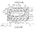
- an annular gap 36 is provided between the tip on the inboard side of the cylindrical portion 24 ⁇ / b> A of the first seal member 24 and the outer end edge of the second seal member 26. .
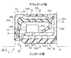
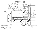
- a space 42 between the annular portion 24B of the first seal member 24 and the flange portion 34B of the second seal member 26 (a space between the surface 24E of the annular portion 24B and the surface 34C of the flange portion 34B).
- a space 46 between the annular portion 24B of the first seal member 24 and the elastic ring 32 of the second seal member 26 between the surface 24E of the annular portion 24B and the surface 32A of the elastic ring 32.
- Foreign matter may enter the space. Conversely, foreign matter in the spaces 42 and 46 can be discharged through the gap 36.
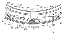
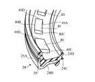
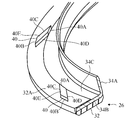
- the second seal member 26 supports a plurality of water discharge protrusions 40 that protrude toward the annular portion 24B of the first seal member 24. These water discharge protrusions 40 have the same shape and the same size, and are arranged at equiangular intervals in the circumferential direction. These water discharge protrusions 40 protrude into the space 46.
- the plurality of water discharge protrusions 40 are integrally attached to the portion of the elastic ring 32 that covers the surface 34C of the flange portion 34B of the rigid ring 34 of the second seal member 26. That is, the water discharge protrusion 40 is a portion of the elastic ring 32. Therefore, the water discharge protrusion 40 is formed of the same material as the elastic ring 32, that is, an elastomer material containing magnetic metal powder and ceramic powder.
- each water discharge protrusion 40 has a substantially quadrangular prism shape, specifically, a substantially rhombic prism shape. More specifically, each water discharge protrusion 40 has a substantially rhombic outline defined by an inner arc surface 40A, an outer arc surface 40B, and two inclined side surfaces 40C and 40D. As shown in FIG. 2, the bottom surface 40F of the quadrangular prism of each water discharge protrusion 40 is parallel to the surface 34C facing the annular portion 24B of the flange portion 34B and is the same as the surface 32A facing the annular portion 24B of the elastic ring 32. The top surface 40E of the quadrangular prism is parallel to the surfaces 32A and 34C.
- an arrow R1 indicates the rotation direction of the second seal member 26 (the rotation direction of the inner ring 6) when the automobile provided with the hub bearing 1 moves forward.
- the arc surfaces 40A and 40B extend in an arc shape along the rotation direction R1. That is, each of the arc surfaces 40A and 40B overlaps a circle (not shown) concentric with the sleeve portion 34A.
- the inclined side surface 40C intersects the rotation direction R1 with an acute angle
- the inclined side surface 40D intersects the rotation direction R1 with an obtuse angle.
- the inclined side surfaces 40C and 40D are parallel to each other.
- each water discharge protrusion 40 protrude into the space 46, and each water discharge protrusion 40 has an inclined side surface 40C that intersects at an acute angle with respect to the rotation direction R1 of the inner ring 6 (see FIG. 6). Therefore, as the inner ring 6 and the second seal member 26 rotate, the water in the space 46 is inclined relative to the rotation of the second seal member 26 as shown by the arrow f1 in FIG. Along the inner ring 6 and the second seal member 26 in the direction opposite to the rotation direction R1.
- the inclined side surface 40C that intersects the rotation direction R1 at an acute angle promotes a smooth flow of water.
- the water flowing in this way is immediately discharged from the space 46 through the gap 36 (see FIG. 2).
- the sealing device 21 has high protection performance from the water to the hub bearing 1 to be sealed.
- the sealing device 21 itself is also reduced in accelerated deterioration due to the presence of water (including muddy water or salt water). Since the gap 36 is annular, water flows out of the space 46 through a part of the gap 36, while air outside the sealing device 21 flows into the space 46 through the other part of the gap 36. To do.
- the air flowing into the space 46 promotes the outflow of water from the space 46. Further, the possibility that the inside of the space 46 becomes negative pressure and the lips 24C and 24D are deformed unexpectedly is reduced.
- the sealing device 21 since the sealing device 21 has a high water discharge performance by the water discharge protrusion 40, the axial lip 24D for preventing the intrusion of foreign matter may not necessarily be provided.
- the axial lip 24D When the axial lip 24D is not provided, no torque is generated due to the axial lip 24D sliding on the second seal member 26 when the inner ring 6 and the second seal member 26 are rotated. Therefore, the energy efficiency of the automobile can be increased.
- the axial lip 24D is provided in order to increase the certainty of preventing foreign matter. Even in this case, since the water discharge performance by the water discharge protrusion 40 is high, it is not necessary to increase the contact pressure of the axial lip 24D with respect to the flange portion 34B of the second seal member 26. Therefore, it is possible to suppress or reduce the torque resulting from the sliding of the axial lip 24D to the second seal member 26 while improving the water discharge performance.
- the axial lip 24D is provided, as in this embodiment, the water discharge protrusion 40 is disposed closer to the gap 36 than the axial lip 24D (positioned between the axial lip 24D and the gap 36). Are preferred).
- the water discharge protrusion 40 preferably protrudes into the space 46 connected to the atmosphere.
- the air outside the sealing device 21 flows into the space 46 in which the water discharge protrusions 40 are arranged through the gap 36, so that the water from the space 46 is discharged. Outflow is promoted.
- each water discharge protrusion 40 is disposed at a position that does not overlap the axial lip 24D. Therefore, when the inner ring 6 rotates, the water discharge protrusion 40 does not collide with or slide on the axial lip 24D, and excessive wear of the axial lip 24D is suppressed.
- each water discharge protrusion 40 is disposed with a space from the cylindrical portion 24A and the annular portion 24B of the first seal member 24. Therefore, when the inner ring 6 rotates, the water discharge protrusion 40 does not collide with or slide on the first seal member 24.
- the surface 32 ⁇ / b> A that faces the annular portion 24 ⁇ / b> B of the elastic ring 32 of the second seal member 26 faces the flange portion 34 ⁇ / b> B of the annular portion 24 ⁇ / b> B of the first seal member 24. It is parallel to the surface 24E. That is, the surface 32 ⁇ / b> A on which the water discharge protrusion 40 is formed is parallel to the surface 24 ⁇ / b> E ahead of the water discharge protrusion 40. In other words, the two surfaces defining the space 46 in which the plurality of water discharge protrusions 40 are arranged are parallel. Therefore, the efficiency with which water is discharged by the water discharge protrusion 40 is better than when the two surfaces are not parallel.
- each water discharge protrusion 40 has a quadrangular prism shape, and the bottom surface 40F of the quadrangular column is parallel to the surface 34C facing the annular portion 24B of the flange portion 34B, and the annular portion 24B of the elastic ring 32.
- the top surface 40E of the quadrangular prism is parallel to the surface 34C of the flange portion 34B and the surface 32A of the elastic ring 32. Therefore, compared with the case where each water discharge protrusion 40 is, for example, a tapered shape that becomes narrower from the bottom toward the top, the cross-sectional area of the water discharge protrusion (the radial cross section of the sealing device 21, that is, the paper surface of FIG. Area) can be increased, and the efficiency with which water is discharged by the water discharge protrusion 40 is good.
- each water discharge projection 40 in the rotation direction of the inner ring 6 is the radial direction of the first seal member 24 and the second seal member 26. It is larger than the length of each water discharge protrusion 40.
- each water discharge protrusion 40 has a maximum length (the apex formed by the inner arc surface 40A and the inclined side surface 40C) and the outer arc surface 40B along the rotation direction R1 of the second seal member 26 (the rotation direction of the inner ring 6). And the apex formed by the inclined side surface 40D).
- the entire water discharge protrusion 40 does not disappear in a short period of time. . That is, the water discharge protrusion 40 has a long life.
- each water discharge protrusion 40 is a space 42 between the annular portion 24B of the first seal member 24 and the flange portion 34B of the second seal member 26, more specifically, the first seal member. 24 protrudes into a space 46 between the annular portion 24B of 24 and the elastic ring 32 of the second seal member 26. Therefore, as apparent from FIGS. 2 and 3, the plurality of water discharge protrusions 41 are disposed within the maximum diameter range of the first seal member 24. For this reason, it is not necessary to increase the size of the sealing device 21 and thus the hub bearing 1.
- the plurality of water discharge protrusions 40 are made of the same material as the elastic ring 32, that is, an elastomer material containing magnetic metal powder and ceramic powder. Since the water discharge protrusion 40 contains metal powder and ceramic powder, it has high durability against the impact of hard foreign matter and high wear resistance.
- the plurality of water discharge protrusions 40 are integrally attached to the elastic ring 32 that covers the flange portion 34B of the rigid ring 34 of the second seal member 26. Therefore, since the number of parts is reduced, the assembly of the sealing device 21 is easy.
- the method for forming the water discharge protrusion 40 may be, for example, press working using a mold or injection molding. In this case, the water discharge protrusion 40 may be formed simultaneously with the formation of the elastic ring 32. However, the water discharge protrusion 40 may be joined to the flange portion 34B by bonding the water discharge protrusion 40, or the water discharge protrusion 40 may be formed by cutting the elastic ring 32.
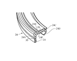
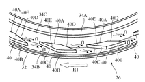
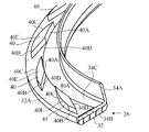
- FIG. 7 is a perspective view showing the second seal member 26 of the sealing device 21 according to a modification of the first embodiment.
- the same reference numerals are used to indicate the components already described, and those components will not be described in detail.
- each water discharge protrusion 50 provided on the flange portion 34B of the second seal member 26 has a shape of a substantially triangular column or a substantially trapezoidal column. More specifically, each water discharge protrusion 50 has a substantially triangular or substantially trapezoidal outline defined by an inner arcuate surface 50A, an outer arcuate surface 50B, and two inclined side surfaces 50C and 50D. The lengths of the two inclined side surfaces 50C and 50D are equal. However, the outer arc surface 50B may be excluded and the outline of each water discharge protrusion 50 may be an isosceles triangle.
- each water discharge protrusion 50 is parallel to the surface 34C facing the annular portion 24B of the flange portion 34B and is flush with the surface 32A facing the annular portion 24B of the elastic ring 32, and the top of the quadrangular column.
- the surface 50E is parallel to the surface 34C.
- each water discharge protrusion 50 has two inclined side surfaces 50C and 50D that intersect at an acute angle with respect to the two rotation directions R1 and R2 in which the inner ring 6 and the second seal member 26 rotate.
- an arrow R ⁇ b> 1 indicates the rotation direction of the second seal member 26 (the rotation direction of the inner ring 6) when the automobile provided with the hub bearing 1 moves forward.
- Arrow R2 indicates the direction of rotation of the second seal member 26 (the direction of rotation of the inner ring 6) when the automobile provided with the hub bearing 1 is moved backward.
- the arc surfaces 50A and 50B extend in an arc shape along the rotation directions R1 and R2.
- each of the arc surfaces 50A and 50B overlaps a circle (not shown) concentric with the sleeve portion 34A.
- the inclined side surface 50C intersects the rotation direction R1 with an acute angle and intersects the rotation direction R2 with an obtuse angle.
- the inclined side surface 50D intersects the rotation direction R1 with an obtuse angle and intersects the rotation direction R2 with an acute angle.
- the water in the space 46 is relatively relative to the rotation of the second seal member 26, as indicated by an arrow f1 in FIG. It flows in the direction opposite to the rotation direction R1 of the inner ring 6 and the second seal member 26 along the inclined side surface 50C.
- the inclined side surfaces 50C that intersect at an acute angle with respect to the rotation direction R1 promote a smooth flow of water.
- the water in the space 46 is relative to the rotation of the second seal member 26 as shown by an arrow f2 in FIG.
- the inner ring 6 and the second seal member 26 flow in the direction opposite to the rotational direction R2 along the inclined side surface 50D.
- the inclined side surface 50D that intersects the rotation direction R2 at an acute angle promotes a smooth flow of water.
- the water flowing in this way is immediately discharged from the space 46 through the gap 36 (see FIG. 2).
- the sealing device 21 has high protection performance from the water to the hub bearing 1 to be sealed.
- the sealing device 21 itself is also reduced in accelerated deterioration due to the presence of water (including muddy water or salt water). Since the gap 36 is annular, water flows out of the space 46 through a part of the gap 36, while air outside the sealing device 21 flows into the space 46 through the other part of the gap 36. To do.
- the air flowing into the space 46 promotes the outflow of water from the space 46. Further, the possibility that the inside of the space 46 becomes negative pressure and the lips 24C and 24D are deformed unexpectedly is reduced.
- the sealing device 21 according to this modification can be shared by both the left and right wheels of the automobile, and can discharge water by the water discharge protrusion 50 when the automobile is moving forward and backward.
- the operator does not have to be careful about which wheel the sealing device is for.
- each water discharge protrusion 50 has a substantially triangular or substantially trapezoidal column shape, and the bottom surface of the approximately triangular or substantially trapezoidal column is parallel to the surface 34C facing the annular portion 24B of the flange portion 34B.
- the top surface 50E of the substantially triangular or substantially trapezoidal column is parallel to the surface 34C of the flange portion 34B and the surface 32A of the elastic ring 32, which is the same surface as the surface 32A facing the annular portion 24B of the elastic ring 32.
- each water discharge protrusion 50 is, for example, a tapered shape that becomes thinner from the bottom toward the top, the cross-sectional area of the water discharge protrusion (area in the radial cross section of the sealing device 21) is increased. The efficiency with which water is discharged by the water discharge protrusion 50 is good.
- each water discharge projection 50 in the rotational directions R1 and R2 is the length of each water discharge projection 50 in the radial direction of the sealing device 21 (that is, the arc surfaces 50A and 50B). The distance between). Therefore, even if a hard foreign matter collides with the water discharge protrusion 50 and the water discharge protrusion 50 is damaged, or the water discharge protrusion 50 is worn by the water flow, the entire water discharge protrusion 50 does not disappear in a short period of time. . That is, the water discharge protrusion 50 has a long life.
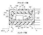
- FIG. 8 is a partial cross-sectional view of a sealing device 21 according to another modification of the first embodiment.
- the first seal member 24 includes an axial lip (side lip) 24F in addition to the axial lip 24D of the first embodiment.
- the axial lip 24F is formed on the radially outer side than the axial lip 24D, extends laterally from the surface 24E of the annular portion 24B, and has a distal end extending radially outward and toward the inboard side. 26 flange portions 34B are contacted.
- the axial lip 24 ⁇ / b> F mainly plays a role in preventing foreign matters from flowing into the hub bearing 1 from the outside.
- Each water discharge protrusion 40 is disposed at a position where it does not overlap with the axial lips 24D, 24F. Therefore, when the inner ring 6 rotates, the water discharge protrusion 40 does not collide with or slide on the axial lips 24D, 24F, and excessive wear of the axial lips 24D, 24F is suppressed.
- two axial lips 24D and 24F are provided in order to increase the certainty of preventing foreign matter. Even in this case, since the water discharge performance by the water discharge protrusion 40 is high, it is not necessary to increase the contact pressure of the axial lips 24D and 24F with respect to the flange portion 34B of the second seal member 26. Therefore, it is possible to suppress or reduce the torque caused by the sliding of the axial lips 24D and 24F on the second seal member 26 while improving the water discharging performance.
- the number of axial lips may be three or more.
- the water discharge protrusion 40 is disposed closer to the gap 36 than the outermost axial lip 24F as in this example (the outermost axial lip 24F and the gap 36 It is preferable to arrange them at a position between them.
- the water discharge protrusion 40 preferably protrudes into the space 46 connected to the atmosphere.
- FIG. 9 is a partial cross-sectional view of a sealing device according to another modification of the first embodiment.
- each water discharge protrusion 40 is not integrally attached to the flange portion 34 ⁇ / b> B of the rigid ring 34 of the second seal member 26.
- An annular plate 54 is overlaid on the flange portion 34 ⁇ / b> B, and each water discharge protrusion 40 is integrally attached to the annular plate 54.
- the annular plate 54 is made of a rigid material, for example, a metal material, and the water discharge protrusion 40 is made of the same rigid material as the annular plate 54, for example, a metal material. Therefore, the water discharge protrusion 40 has high durability against the impact of hard foreign matter and high wear resistance.
- the annular plate 54 is disposed in the space 42 between the annular portion 24B of the first seal member 24 and the flange portion 34B of the second seal member 26, and is in contact with the surface 34C of the flange portion 34B.
- the annular plate 54 is disposed on the radially outer side of the sleeve portion 34 ⁇ / b> A of the second seal member 26, spreads radially outward, and faces the annular portion 24 ⁇ / b> B of the first seal member 24.
- the surface 54A of the annular plate 54 facing the annular portion 24B is parallel to the surface 24E of the annular portion 24B of the first seal member 24 and the surface 34C of the flange portion 34B of the second seal member 26. It is.
- the water discharge protrusion 40 protrudes into the space 56 between the two surfaces 24E and 54A parallel to each other. Therefore, the efficiency with which water is discharged by the water discharge protrusion 40 is better than when the two surfaces are not parallel.
- each water discharge protrusion 40 has a quadrangular prism shape, and the bottom surface 40F of the quadrangular column is parallel to the surface 34C facing the annular portion 24B of the flange portion 34B, and the surface 54A of the annular plate 54 is provided.
- the top surface 40E of the quadrangular prism is parallel to the surface 34C of the flange portion 34B. Therefore, compared with the case where each water discharge protrusion 40 is, for example, a tapered shape that becomes narrower from the bottom toward the apex, the cross-sectional area of the water discharge protrusion (the radial cross section of the sealing device 21, that is, the paper surface of FIG. Area) can be increased, and the efficiency with which water is discharged by the water discharge protrusion 40 is good.
- the annular plate 54 and the water discharge protrusion 40 are made of a metal material.
- the annular plate 54 and the water discharge protrusion 40 are, for example, a resin material containing metal powder, a resin material containing ceramic powder, a resin material containing both metal powder and ceramic powder, and an elastomer containing metal powder. You may form from the material, the elastomer material containing ceramic powder, or the elastomer material containing both metal powder and ceramic powder. Since these materials contain at least one of metal powder and ceramic powder, they have higher hardness than ordinary resin materials or elastomer materials and are not easily damaged by foreign substances. Even in this case, the water discharge protrusion 40 has high durability against the impact of hard foreign matters and high wear resistance. Furthermore, the annular plate 54 and thus the water discharge protrusion 40 may be formed of a resin material or an elastomer material that does not contain metal powder or ceramic powder.
- the method of forming the water discharge protrusion 40 may be, for example, press working using a mold or injection molding.
- the water discharge protrusion 40 is formed at the same time as the annular plate 54 is formed. May be.
- the water discharge protrusion 40 may be joined to the annular plate 54 by welding, soldering or bonding, or the water discharge protrusion 40 may be formed by cutting the annular plate 54.
- the water discharge protrusion 40 is formed on a separate annular plate 54 that can be easily separated from the second seal member 26.
- the annular plate 54 may be joined to the flange portion 34 ⁇ / b> B of the second seal member 26.
- FIG. 10 is a partial cross-sectional view of a sealing device according to another modification of the first embodiment.
- the annular plate 54 is not used, and each water discharge protrusion 40 is directly and integrally attached to the flange portion 34B of the rigid ring 34 of the second seal member 26. That is, each water discharge protrusion 40 is a part of the rigid ring 34.
- the bottom surface 40F of each water discharge protrusion 40 is flush with the surface 34C facing the annular portion 24B of the flange portion 34B.
- the water discharge protrusion 40 is formed of the same rigid material as the rigid ring 34, for example, a metal material. Therefore, the water discharge protrusion 40 has high durability against the impact of hard foreign matter and high wear resistance.
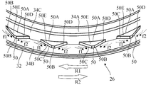
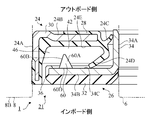
- the plurality of water discharge protrusions 60 are integrally attached to a portion of the elastic ring 32 that covers the surface 34C of the flange portion 34B of the rigid ring 34 of the second seal member 26. That is, the water discharge protrusion 60 is a portion of the elastic ring 32. Therefore, the water discharge protrusion 60 is formed of the same material as the elastic ring 32, that is, an elastomer material containing magnetic metal powder and ceramic powder.
- each water discharge protrusion 60 provided on the flange portion 34B of the second seal member 26 has a substantially triangular pyramid shape. More specifically, each water discharge protrusion 60 has a substantially triangular first inclined side surface 60A, a substantially triangular second inclined side surface 60B, a substantially triangular third inclined side surface 60C, and a substantially triangular bottom surface 60D. Have. However, the top portion where the inclined side surfaces 60A, 60B, 60C are adjacent is flat. As shown in FIG. 13, the bottom surface 60D is parallel to the surface 34C facing the annular portion 24B of the flange portion 34B and is flush with the surface 32A facing the annular portion 24B of the elastic ring 32.
- the outline of the first inclined side surface 60A is substantially an isosceles triangle, and the length of the side between the first inclined side surface 60A and the second inclined side surface 60B is the first inclined side surface 60A and the third inclined side surface. It is equal to the length of the side between the side surface 60C.
- arrow R1 indicates the rotation direction of the second seal member 26 (the rotation direction of the inner ring 6) when the automobile provided with the hub bearing 1 moves forward.
- the first inclined side surface 60A and the second inclined side surface 60B intersect with the rotation direction R1 with an acute angle.
- the side between the third inclined side surface 60C and the bottom surface 60D extends along the rotation direction R1, and is parallel to the rotation direction R1.
- the water in the space 46 is relatively inclined with respect to the rotation of the second seal member 26 as shown by an arrow f1 in FIG. It flows in the direction opposite to the rotational direction R1 of the inner ring 6 and the second seal member 26 along 60A and the second inclined side surface 60B. That is, water flows through the flow path between the first inclined side surface 60A of a certain water discharge protrusion 60 and the second inclined side surface 60B of the adjacent water discharge protrusion 60.
- the first inclined side surface 60A and the second inclined side surface 60B that intersect at an acute angle with respect to the rotation direction R1 promote a smooth flow of water.
- the water flowing in this way is immediately discharged from the space 46 through the gap 36 (see FIG. 2).
- the sealing device 21 has high protection performance from the water to the hub bearing 1 to be sealed. Further, the sealing device 21 itself is also reduced in accelerated deterioration due to the presence of water (including muddy water or salt water). Since the gap 36 is annular, water flows out of the space 46 through a part of the gap 36, while air outside the sealing device 21 flows into the space 46 through the other part of the gap 36. Is possible. Therefore, the possibility that the inside of the space 46 becomes negative pressure and the lips 24C and 24D deform unexpectedly is reduced.
- the sealing device 21 since the sealing device 21 has a high water discharging performance by the water discharging protrusion 60, the axial lip 24D for preventing the intrusion of foreign matters may not necessarily be provided.
- the axial lip 24D When the axial lip 24D is not provided, no torque is generated due to the axial lip 24D sliding on the second seal member 26 when the inner ring 6 and the second seal member 26 are rotated. Therefore, the energy efficiency of the automobile can be increased.
- an axial lip 24D is provided in order to increase the certainty of preventing foreign matter. Even in this case, since the water discharge performance by the water discharge protrusion 60 is high, it is not necessary to increase the contact pressure of the axial lip 24D with respect to the flange portion 34B of the second seal member 26. Therefore, it is possible to suppress or reduce the torque resulting from the sliding of the axial lip 24D to the second seal member 26 while improving the water discharge performance.
- the axial lip 24D is provided, as in this example, the water discharge protrusion 40 is disposed closer to the gap 36 than the axial lip 24D (ie, disposed at a position between the axial lip 24D and the gap 36). ) Is preferred. In other words, the water discharge protrusion 40 preferably protrudes into the space 46 connected to the atmosphere.
- each water discharge protrusion 60 is arranged at a position that does not overlap with the axial lip 24D. Therefore, when the inner ring 6 rotates, the water discharge protrusion 60 does not collide with or slide on the axial lip 24D, and excessive wear of the axial lip 24D is suppressed.
- each water discharge protrusion 60 is disposed at a distance from the cylindrical portion 24A and the annular portion 24B of the first seal member 24. Therefore, when the inner ring 6 rotates, the water discharge protrusion 60 does not collide with or slide on the first seal member 24.
- the surface 32A facing the annular portion 24B of the elastic ring 32 of the second seal member 26 is the surface facing the flange portion 34B of the annular portion 24B of the first seal member 24. It is parallel to 24E. That is, the surface 32 ⁇ / b> A on which the water discharge protrusion 60 is formed is parallel to the surface 24 ⁇ / b> E on the front side of the water discharge protrusion 60. In other words, the two surfaces that define the space 46 in which the plurality of water discharge protrusions 60 are arranged are parallel. Therefore, the efficiency with which water is discharged by the water discharge protrusion 60 is better than when the two surfaces are not parallel.
- the length of each water discharge projection 60 in the rotation direction of the inner ring 6 is different from each other in the radial direction of the first seal member 24 and the second seal member 26. It is larger than the length of the water discharge protrusion 60. Therefore, even if a hard foreign matter collides with the water discharge protrusion 60 and the water discharge protrusion 60 is damaged, or the water discharge protrusion 60 is worn by the water flow, the entire water discharge protrusion 60 does not disappear in a short period of time. . That is, the water discharge protrusion 60 has a long life.
- each water discharge protrusion 60 is a space 42 between the annular portion 24B of the first seal member 24 and the flange portion 34B of the second seal member 26, more specifically, the first seal member. 24 protrudes into a space 46 between the annular portion 24B of 24 and the elastic ring 32 of the second seal member 26. Therefore, as apparent from FIGS. 11 and 13, the plurality of water discharge protrusions 60 are disposed within the maximum diameter range of the first seal member 24. For this reason, it is not necessary to increase the size of the sealing device 21 and thus the hub bearing 1.
- each water discharge protrusion 60 is integrally attached to the elastic ring 32 that covers the flange portion 34B of the rigid ring 34 of the second seal member 26.
- each water discharge protrusion 60 is integrated with an annular plate 54 (not shown in FIGS. 11 to 13) superimposed on the flange portion 34B. It may be attached to.
- each water discharge projection 60 may be directly and integrally attached to the flange portion 34 ⁇ / b> B of the rigid ring 34 of the second seal member 26.
- each water discharge protrusion 60 may be a part of the rigid ring 34.
- the bottom surface 60D of each water discharge protrusion 60 is the same surface as the surface 34C facing the annular portion 24B of the flange portion 34B.
- the water discharge protrusion 60 is formed of the same rigid material as the rigid ring 34, for example, a metal material. Therefore, the water discharge protrusion 60 has high durability against the impact of hard foreign matter and high wear resistance.
- FIG. 15 and 16 show a sealing device 21 according to still another modification of the first embodiment.
- a first seal member 24 and a second seal member 26 different from those of the first embodiment are used.
- the cylindrical portion 24A extends in the opposite direction to the cylindrical portion 24A of the first embodiment.
- An inclined connecting portion 24G is connected to the inner end edge of the annular portion 24B, and lips 24C and 24D extend from the inner end of the inclined connecting portion 24G.
- the inclined connecting portion 24G includes a rigid ring 30 and an elastic ring 28.
- the second seal member 26 does not have the elastic ring 32 and is configured only from the rigid ring 34.
- the flange portion 34B of the rigid ring 34 is a curved plate.
- Each water discharge protrusion 40 is integrally attached to the flange portion 34 ⁇ / b> B of the rigid ring 34 of the second seal member 26. That is, the water discharge protrusion 40 is a portion of the rigid ring 34. Therefore, the water discharge protrusion 40 is formed of the same rigid material as the rigid ring 34, for example, a metal material.
- Each water discharge protrusion 40 protrudes into a space 42 between the annular portion 24B of the first seal member 24 and the flange portion 34B of the second seal member 26.
- the surface 34C facing the annular portion 24B of the flange portion 34B of the second seal member 26 is not parallel to the surface 24E facing the flange portion 34B of the annular portion 24B of the first seal member 24.
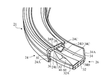
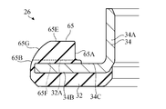
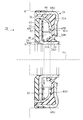
- FIG. 17 shows a sealing device 21 according to still another modification of the first embodiment.
- 18 is a perspective view of the second seal member 26 of this modification
- FIG. 19 is a front view of the second seal member 26
- FIG. 20 is a cross-sectional view taken along the line XX-XX in FIG. .
- FIG. 17 is a cross-sectional view of the sealing device 21 taken along line XVII-XVII in FIG.
- the second seal member 26 supports a plurality of water discharge protrusions 65 that protrude toward the annular portion 24B of the first seal member 24.
- These water discharge protrusions 65 have the same shape and the same size, and are arranged at equiangular intervals in the circumferential direction. As shown in FIG. 17, these water discharge protrusions 65 are formed in the space 42 between the annular portion 24B of the first seal member 24 and the flange portion 34B of the second seal member 26 (more specifically, the annular portion 24B). Projecting into a space 46) between the surface 24E of the elastic ring 32 and the surface 32A of the elastic ring 32.
- the plurality of water discharge protrusions 65 are integrally attached to the portion of the elastic ring 32 that covers the surface 34C facing the annular portion 24B of the flange portion 34B. That is, the water discharge protrusion 65 is a portion of the elastic ring 32. Therefore, the water discharge protrusion 65 is formed of the same material as the elastic ring 32, that is, an elastomer material containing magnetic metal powder and ceramic powder.
- each water discharge protrusion 65 has a substantially quadrangular shape, specifically a substantially rhombic outline, when viewed along the axial direction of the second seal member 26. As shown in FIGS. 17 and 20, each water discharge protrusion 65 has a substantially rectangular outline with one corner formed in an arc shape when viewed from the side of the second seal member 26.
- each water discharge protrusion 65 has a substantially rhombic outline defined by an inner arc surface 65A, an outer arc line 65B, and two inclined side surfaces 65C and 65D.
- the outer arc line 65B substantially coincides with the outer peripheral contour of the elastic ring 32 covering the outer peripheral contour of the rigid ring 34 in the second seal member 26.
- each water discharge protrusion 65 has a substantially rectangular outline defined by an inner circular arc surface 65A, a top surface 65E, a curved surface 65G, and a bottom surface 65F.
- the bottom surface 65F is parallel to the surface 34C facing the annular portion 24B of the flange portion 34B and is flush with the surface 32A facing the annular portion 24B of the elastic ring 32.
- the top surface 65E is parallel to the surfaces 32A and 34C.
- the curved surface 65G is curved in an arc shape so as to move away from the flange portion 34B as it goes radially inward.
- the elastic ring 28 of the first seal member 24 has a curved surface 66 extending from the cylindrical portion 24A to the annular portion 24B.
- the curved surface 66 is curved in an arc shape so as to move away from the flange portion 34B of the second seal member 26 as it goes radially inward.
- the curved surface 65G of the water discharge protrusion 65 faces the curved surface 66 of the first seal member 24 and is formed substantially in parallel with the curved surface 66.
- the curved surface 66 defines a narrow space 42 in which the water discharge protrusion 65 having the curved surface 65G can rotate.
- an arrow R1 indicates the rotation direction of the second seal member 26 (the rotation direction of the inner ring 6) when the automobile provided with the hub bearing 1 moves forward.
- the inner arc surface 65A and the outer arc line 65B extend in an arc shape along the rotation direction R1. That is, each of the inner circular arc surface 65A and the outer circular arc line 65B overlaps a circle (not shown) concentric with the sleeve portion 34A.
- the inclined side surface 65C intersects the rotation direction R1 with an acute angle
- the inclined side surface 65D intersects the rotation direction R1 with an obtuse angle.
- each water discharge protrusion 65 protrude into the space 42, and each water discharge protrusion 65 has an inclined side surface 65C that intersects with the rotation direction R1 of the inner ring 6 at an acute angle (see FIG. 19). Therefore, as the inner ring 6 and the second seal member 26 rotate, the water in the space 42 is inclined relative to the rotation of the second seal member 26 as shown by the arrow f1 in FIG. Along the inner ring 6 and the second seal member 26 in the direction opposite to the rotation direction R1.
- the inclined side surface 65C that intersects the rotation direction R1 at an acute angle promotes a smooth flow of water.
- the water flowing in this way is immediately discharged from the space 42 through the gap 36 (see FIG. 17).
- the sealing device 21 has high protection performance from the water to the hub bearing 1 to be sealed.
- the sealing device 21 itself is also reduced in accelerated deterioration due to the presence of water (including muddy water or salt water). Since the gap 36 is annular, water flows out of the space 42 through a part of the gap 36, while air outside the sealing device 21 flows into the space 42 through the other part of the gap 36. To do.
- the air flowing into the space 42 promotes the outflow of water from the space 42. Further, the possibility that the inside of the space 42 becomes negative pressure and the lips 24C and 24D deform unexpectedly is reduced.
- the first seal member 24 has a curved surface 66
- each water discharge projection 65 has a curved surface 65G
- the curved surface 65G faces the curved surface 66. Since each of the first seal member 24 and the water discharge protrusion 65 is formed with curved surfaces 66 and 65G, foreign substances are unlikely to enter the space 42 between the annular portion 24B and the flange portion 34B from the outside.
- the curved surface 65G of the water discharge protrusion 65 approaches the flange portion 34B as it goes outward in the radial direction, the water discharge performance is high.
- the centrifugal force CF acts on the air in the space 42 as the inner ring 6 and the second seal member 26 rotate.
- the top surface 65E of the water discharge protrusion 65 is disposed perpendicular to the axial direction of the sealing device 21, and the adhesion force AF acts in the axial direction on the water droplet WD attached to the top surface 65E.
- the adhesion force AF is caused by the surface tension or cohesion force of water, and causes water to adhere in the normal direction of this surface toward the surface with which the water comes into contact.
- the water droplet WD adhering to the top surface 65E is moved to the outside in the radial direction, for example, the curved surface 65G by the resultant force of the centrifugal force CF, the adhesion force AF, and gravity.
- the curved surface 65G is inclined with respect to the axial direction of the sealing device 21, and the adhesion force AF acts on the water droplet WD attached to the curved surface 65G in the normal direction of the curved surface 65G.
- the water droplet WD attached to the curved surface 65G is moved radially outward, that is, toward the annular gap 36 by the resultant force of the centrifugal force CF, the adhesion force AF, and gravity.
- the water droplet WD adhering to the curved surface 65G is moved toward the gap 36 by the axial direction component A1 of the adhesion force AF. Therefore, the curved surface 65G promotes water discharge.
- the water droplet WD remains in the space 42 after the rotation of the inner ring 6 and the second seal member 26 is stopped. Above the central axis Ax of the sealing device 21, the water droplet WD falls on the outer peripheral surface of the sleeve portion 34A of the rigid ring 34 or the axial lip 24D through the curved surface 65G of the water discharge projection 65 by gravity.
- the water droplet WD passes through the outer peripheral surface of the sleeve portion 34 ⁇ / b> A or the axial lip 24 ⁇ / b> D by gravity as shown by the broken-line arrow in the drawing, and is below the central axis Ax of the sealing device 21, so that the first seal member 24 is formed.
- the curved surface 66 falls. Since the curved surface 66 is closer to the flange portion 34B as it goes outward in the radial direction, the water droplet WD is quickly discharged from the annular gap 36.
- each water discharge projection 65 in the rotation direction of the inner ring 6 is the same as that of each water discharge in the radial direction of the first seal member 24 and the second seal member 26. It is larger than the length of the protrusion 65.
- each water discharge protrusion 65 has a maximum length (the apex formed by the inner arc surface 65A and the inclined side surface 65C) and the outer arc line 65B along the rotation direction (rotation direction of the inner ring 6) R1 of the second seal member 26. And the apex formed by the inclined side surface 65D).
- the entire water discharge protrusion 65 does not disappear in a short period of time. . That is, the water discharge protrusion 65 has a long life.
- each water discharge protrusion 65 protrudes into the space 42 between the annular portion 24B of the first seal member 24 and the flange portion 34B of the second seal member 26. Therefore, as apparent from FIG. 17, the plurality of water discharge protrusions 65 are disposed within the maximum diameter range of the first seal member 24. For this reason, it is not necessary to increase the size of the sealing device 21 and thus the hub bearing 1.
- annular circular protrusion 67 having an inclined surface 67A may be attached to the second seal member 26 so that the water discharge protrusion 65 protrudes from the inclined surface 67A.
- the circular protrusion 67 protrudes toward the annular portion 24B of the first seal member 24 and has a substantially triangular cross section.
- the circular protrusion 67 has an inclined surface 67A that moves away from the flange portion 34B of the second seal member 26 as it goes radially inward.
- the first seal member 24 has an annular circular protrusion 67 and the plurality of water discharge protrusions 65 protrude from the inclined surface 67A of the circular protrusion 67, the space between the annular portion 24B and the flange portion 34B.
- the shape of 42 becomes more complicated. Therefore, foreign matter is less likely to enter the space 42 from the outside.
- curved surfaces 66 and 65G are formed on the first seal member 24 and the water discharge protrusion 65, respectively.
- an inclined surface 68 may be provided that inclines away from the flange portion 34B as it goes radially inward.
- the first seal member 24 may be provided with an inclined surface 69 that is inclined away from the flange portion 34 ⁇ / b> B and substantially parallel to the inclined surface of the water discharge protrusion 65.
- each inclined side surface 40 ⁇ / b> C may be concavely curved with respect to both ends of the inclined side surface 40 ⁇ / b> C when viewed along the axial direction of the sealing device 21.
- the inclined side surfaces 50C, 50D, and 65C of the water discharge protrusions 50 and 65 may be similarly recessed and curved.
- each inclined side surface 40C may be convexly curved with respect to both ends of the inclined side surface 40C when viewed along the axial direction of the sealing device 21.
- the inclined side surfaces 50C, 50D, and 65C of the water discharge protrusions 50 and 65 may be similarly curved in a convex shape.
- the water discharge protrusion 40 of the embodiment of FIG. 2 may be integrally attached to the flange portion 34 ⁇ / b> B of the rigid ring 34 instead of the elastic ring 32.
- the water discharge protrusion 40 may be formed of a metal material.
- the water discharge protrusion 40 of the modification of FIG. 15 and FIG. 16 may be integrally attached to an annular plate or an elastic ring (not shown) disposed on the flange portion 34B instead of the flange portion 34B of the rigid ring 34.
- the water discharge protrusion 40 may be formed of a metal material, or a resin material, an elastomer material, a resin material containing at least one of metal powder and ceramic powder, or at least one of metal powder and ceramic powder. It may be formed from an elastomeric material.
- FIG. 29 shows the test apparatus used for this test.
- This test apparatus includes a tank 155, a rotation shaft 116, a first seal member 124, a second seal member 126, a rotation plate 150, and an outer wall member 118.
- the rotating shaft 116 imitates the inner ring 6 but is a solid round bar.
- the rotating shaft 116 is rotated around a central axis Ax that is disposed horizontally.
- the outer wall member 118 imitates the outer ring 8 and has a circular through hole 119.
- the boundary between the outer periphery of the lower portion of the outer wall member 118 and the inner surface of the tank 155 is sealed.
- the first seal member 124, the second seal member 126, and the rotating plate 150 are disposed on the radially inner side of the through hole 119 of the outer wall member 118.
- the first seal member 124 imitates the first seal member 24 according to the first embodiment and the modified example, but does not have lips such as a radial lip 24C and an axial lip 24D.
- the first seal member 124 is a fixed seal member that is attached to the outer wall member 118 and does not rotate.
- the first seal member 124 is a composite structure having the elastic ring 28 and the rigid ring 30.
- the first seal member 124 has a cylindrical portion 24A and an annular portion 24B.
- the cylindrical portion 24A is fitted (that is, press-fitted) into the through hole 119 of the outer wall member 118 by an interference fit method.
- the second seal member 126 and the rotating plate 150 cooperate to imitate the second seal member 26 of the first embodiment and the modified example.
- the second seal member 126 has a rigid ring 34 and an elastic ring 132 of the second seal member 26.
- the end of the rotating shaft 116 is fitted into the sleeve portion 34A of the rigid ring 34 by an interference fitting method (that is, press-fitted).
- the elastic ring 132 is in close contact with the flange portion 34 ⁇ / b> B of the rigid ring 34.
- the rotating plate 150 has a disc portion 152 and an annular portion 154.
- the disc portion 152 is disposed concentrically with the rotating shaft 116 and faces the end of the rotating shaft 116.
- the annular portion 154 is disposed concentrically with the disc portion 152, and extends from the radially outer portion of the disc portion 152 toward the annular portion 24 ⁇ / b> B of the first seal member 124.
- the annular portion 154 is disposed inside the cylindrical portion 24A of the first seal member 124, and an annular gap 136 is provided between the annular portion 154 and the cylindrical portion 24A.
- the gap 136 corresponds to the gap 36 of the first embodiment and the modified example.
- the flange portion 34B of the rigid ring 34 is fitted (that is, press-fitted) into the annular portion 154 of the rotating plate 150 by an interference fit method.
- the elastic ring 132 is compressed between the flange portion 34B and the disc portion 152 of the rotating plate 150, and seals the gap between the flange portion 34B and the disc portion 152.
- the surface of the annular portion 154 on the annular portion 24B side is the same or parallel to the surface 34C facing the annular portion 24B of the flange portion 34B. These surfaces are separated from the annular portion 24B, and a space 146 is provided between these surfaces and the annular portion 24B.
- the space 146 corresponds to the space 46 of the first embodiment and the modified example.
- a plurality of water discharge protrusions 140 are formed on the surface of the annular portion 154 on the annular portion 24B side.
- the water discharge protrusion 140 corresponds to the water discharge protrusion 40 of the first embodiment, and has a substantially quadrangular prism shape, specifically, a substantially rhombic pillar shape.
- the illustrated test apparatus has a shape imitating the first embodiment shown in FIG. 2 or the modification shown in FIG.
- the rotating shaft 116 rotates
- the second seal member 126 and the rotating plate 150 rotate together with the water discharge protrusion 140.
- the first seal member 124 fixed to the outer wall member 118 is maintained in a stationary state.
- the first seal member 124 does not have a lip.
- a gap 128 is provided between the inner end edge of the first seal member 124 and the rigid ring 34 of the second seal member 126.
- a test apparatus for comparison without the water discharge protrusion 140 was prepared.
- a comparative test apparatus provided with a plurality of substantially triangular pyramid water discharge protrusions was also prepared. This test apparatus has a shape imitating the modification shown in FIG. 13 or the modification shown in FIG.
- the rotation speed of the rotating shaft 116 was changed for each of these test apparatuses, and the weight of the water W flowing out for 1 minute through the gap 128 was measured at each rotation speed. From the measured weight, the amount of water flowing out per unit time, that is, the flow rate (g / min) was calculated.
- the water surface is discharged after the height of the water surface becomes the height of the central axis Ax of the rotating shaft 116.
- the weight of water W was measured. Under each condition, the measurement was performed 5 times and the average value was calculated.
- the calculated flow rate can be considered as the amount of water reaching the axial lip 24D of the sealing device 21 in an environment where there is a lot of water in the surroundings.
- FIG. 30 shows the results of this test.
- the water W was splashed by the rotation of the rotating plate 150 attached to the rotating shaft 116, and thus the flow rate became zero.
- the flow rate of the test apparatus provided with a plurality of water discharge projections 140 having a substantially rectangular column was clearly smaller than that of the other test apparatuses, and the flow rate became zero at the lowest rotational speed. This is presumed to be because more water W is discharged by the substantially rectangular water discharge protrusion 140 that rotates together with the rotating plate 150.
- the flow rate of the test apparatus provided with a plurality of substantially triangular prism water discharge protrusions was smaller than that of the test apparatus without the water discharge protrusions, and the flow rate became zero at a lower rotational speed. As described above, the water discharge effect by the plurality of water discharge protrusions could be confirmed.
- the first embodiment described above relates to the sealing device 21 on the inboard side of the hub bearing 1.
- the second embodiment of the present invention relates to a sealing structure including a sealing device 20 on the outboard side of the hub bearing 1.
- the sealing device (seal member) 20 is disposed in a gap between the end portion 8A on the outboard side of the outer ring 8 of the hub bearing 1 and the hub 4 of the hub bearing 1.
- the sealing device 20 includes a cylindrical end portion 8A on the outboard side of the outer ring 8 of the hub bearing 1, an outer peripheral surface 4A of a cylindrical portion near the ball 10 of the hub 4 of the hub bearing 1, and a hub. 4 is arranged in a space surrounded by a flange surface 4B spreading outward in the radial direction from the outer peripheral surface 4A and an arcuate surface 4C connecting the outer peripheral surface 4A and the flange surface 4B.
- the flange surface 4B is a surface on the inboard side of the outboard side flange 18.
- the sealing device 20 is a composite structure having an elastic ring 164 and a rigid ring 165.
- the elastic ring 164 is made of an elastic material such as an elastomer.
- the rigid ring 165 is made of a rigid material, for example, metal, and reinforces the elastic ring 164.
- a part of the rigid ring 165 is embedded in the elastic ring 64 and is in close contact with the elastic ring 64.
- the elastic ring 164 has a cylindrical portion 164A, an inclined connecting portion 164B, an annular portion 164C, and lips 172, 174, and 176.
- the cylindrical portion 164A is fitted (that is, press-fitted) into the inner peripheral surface of the end portion 8A of the outer ring 8 by an interference fit method.
- the inclined connecting portion 164B is disposed on the radially inner side of the cylindrical portion 164A.
- the annular portion 164C connects the cylindrical portion 164A and the inclined connection portion 164B.
- the lips 172, 174, 176 extend from the inclined connection portion 164 B toward the hub 4 of the hub bearing 1.
- the annular portion 164C has an annular shape, and is directed radially inward from the one end of the cylindrical portion 164A toward the outer peripheral surface 4A of the cylindrical portion of the hub 4 so as to be orthogonal to the central axis Ax of the hub bearing 1. It has spread. Further, the annular portion 164 ⁇ / b> C faces the flange surface 4 ⁇ / b> B of the outboard side flange 18. In this embodiment, the surface 164E facing the flange surface 4B of the annular portion 164C is parallel to the flange surface 4B.
- the inclined coupling portion 164B extends obliquely from the annular portion 164C radially inward and toward the inboard side, is bent, and is further radially orthogonal to the central axis Ax of the hub bearing 1. It extends inward.
- Each of the lips 172, 174, and 176 is made of only an elastic material, and is a thin plate-like ring extending from the inclined connection portion 164 B. Each tip contacts the hub 4. While the sealing device 20 is attached to the fixed outer ring 8, the hub 4 rotates, so that the lips 172, 174, 176 slide relative to the hub 4.
- the lip 172 is a radial lip or grease lip that extends from the innermost edge of the inclined connecting portion 164B and extends toward the cylindrical portion near the ball 10 of the hub 4, and the tip of the radial lip 172 is at the cylindrical portion. It contacts the outer peripheral surface 4A.
- the radial lip 172 extends radially inward and toward the inboard side, and plays a role of mainly preventing the lubricant from flowing out from the inside of the hub bearing 1.
- the lips 174 and 176 extend from the inclined connection portion 164B to the side (outboard side) and radially outward.
- the lip 174 is an axial lip or a side lip and extends toward the flange surface 4B of the hub 4.
- the tip of the axial lip 174 contacts the flange surface 4B or the arc surface 4C.
- the lip 176 is called an axial lip or an intermediate lip and extends toward the arc surface 4C, and the tip of the intermediate lip 176 contacts the arc surface 4C.
- the lips 174 and 176 mainly play a role of preventing foreign matters from flowing into the hub bearing 1 from the outside.
- the intermediate lip 176 has a backup function that prevents foreign matter that has passed through the axial lip 174.
- the rigid ring 165 has a cylindrical portion 165A, an annular portion 165B, a connecting portion 165C, and an annular portion 165D.
- the cylindrical portion 165 ⁇ / b> A is fitted into the inner peripheral surface of the end portion 8 ⁇ / b> A of the outer ring 8.
- the annular portion 165B is disposed on the radially inner side of the cylindrical portion 165A, and is disposed so as to be orthogonal to the central axis Ax of the hub bearing 1.
- the connecting portion 165C connects the cylindrical portion 165A and the annular portion 165B.
- FIG. 31 shows the cylindrical portion 165A in a compressed state.
- the cylindrical portion 165A of the rigid ring 165 and the cylindrical portion 164A of the elastic ring 164 constitute an attachment portion 166 that is fitted into the inner peripheral surface of the end portion 8A of the outer ring 8.
- the connecting portion 165C of the rigid ring 165 is in close contact with the cylindrical portion 164A of the elastic ring 164, and the annular portion 165B is in close contact with the annular portion 164C of the elastic ring 164.
- the annular portion 165D is in close contact with the inclined connection portion 164B of the elastic ring 164.
- the annular portion 165D has a bent shape that is substantially similar to the shape of the bent inclined connecting portion 164B.
- annular gap 180 is provided between the end 8 ⁇ / b> A of the outer ring 8 and the flange surface 4 ⁇ / b> B of the hub 4.
- foreign matter may enter the space 182 between the annular portion 164C and the flange surface 4B of the sealing device 20 (the space between the surface 164E of the annular portion 164C and the flange surface 4B).
- the foreign matter in the space 182 can be discharged through the gap 180.
- a plurality of water discharge protrusions 40 projecting toward the annular portion 164C of the sealing device 20 are supported on the outboard side flange 18 of the hub 4.
- These water discharge protrusions 40 have the same shape and the same size, and are arranged at equiangular intervals in the circumferential direction. These water discharge protrusions 40 protrude into the space 182.
- the plurality of water discharge protrusions 40 are integrally attached to the outboard side flange 18 of the sealing device 20. That is, the water discharge protrusion 40 is a portion of the outboard side flange 18. Therefore, the water discharge protrusion 40 is formed of the same rigid material as the outboard flange 18, for example, a metal material.
- Each water discharge protrusion 40 of this embodiment has a substantially quadrangular prism shape, specifically a substantially rhomboid shape, as in the first embodiment (see FIGS. 5 and 6). More specifically, each water discharge protrusion 40 has a substantially rhombic outline defined by an inner arc surface 40A, an outer arc surface 40B, and two inclined side surfaces 40C and 40D. As shown in FIG. 31, the quadrangular prism bottom surface 40F of each water discharge protrusion 40 is flush with the flange surface 4B, and the quadrangular prism top surface 40E is parallel to the flange surface 4B.
- FIG. 6 relating to the first embodiment may be referred to.
- the second seal member 26 can be read as the outboard flange 18 and the surface 34C can be read as the flange surface 4B.
- the arrow R1 can be considered as the rotation direction of the hub 4 when the automobile provided with the hub bearing 1 moves forward.
- the arc surfaces 40A and 40B extend in an arc shape along the rotation direction R1 (see FIG. 6). That is, each of the arc surfaces 40A and 40B overlaps a circle (not shown) concentric with the hub 4 and the outer ring 8.
- the inclined side surface 40C intersects the rotation direction R1 of the hub 4 with an acute angle
- the inclined side surface 40D intersects the rotation direction R1 with an obtuse angle.
- the inclined side surfaces 40C and 40D are parallel to each other.
- each water discharge protrusion 40 protrude into the space 182, and each water discharge protrusion 40 has an inclined side surface 40 ⁇ / b> C that intersects with the rotation direction R ⁇ b> 1 of the hub 4 at an acute angle (see FIG. 6). Therefore, with the rotation of the hub 4, the water in the space 182 flows in the direction opposite to the rotation direction R ⁇ b> 1 of the hub 4 along the inclined side surface 40 ⁇ / b> C relative to the rotation of the hub 4.
- the inclined side surface 40C that intersects the rotation direction R1 at an acute angle promotes a smooth flow of water.
- the water flowing in this way is quickly discharged from the space 182 through the gap 180 (see FIG. 31).
- this sealing structure has high protection performance from the water to the hub bearing 1 to be sealed.
- the sealing device 20 is also reduced in deterioration that accelerates due to the presence of water (including muddy water or salt water). Since the gap 180 is annular, water flows out from the space 182 through a part of the gap 180, while air outside the sealing device 20 flows into the space 182 through the other part of the gap 180. To do.
- the air flowing into the space 182 promotes the outflow of water from the space 182. Further, the possibility that the inside of the space 182 becomes negative pressure and the lips 174 and 176 deform unexpectedly is reduced.
- this sealing structure has high water discharging performance by the water discharging protrusion 40, the axial lip 174 and the intermediate lip 176 that prevent the intrusion of foreign matter are not necessarily provided.
- the axial lip 174 and the intermediate lip 176 are not provided, no torque is generated due to the axial lip 174 and the intermediate lip 176 sliding on the hub 4 when the hub 4 rotates. Therefore, the energy efficiency of the automobile can be increased.
- an axial lip 174 and an intermediate lip 176 are provided in order to increase the certainty of blocking foreign matter. Even in this case, since the water discharge performance by the water discharge protrusion 40 is high, it is not necessary to increase the contact pressure of the axial lip 174 and the intermediate lip 176 with respect to the hub 4. Accordingly, it is possible to suppress or reduce the torque caused by the axial lip 174 and the intermediate lip 176 sliding on the hub 4 while improving the water discharging performance.
- the axial lip 174 and the intermediate lip 176 are provided, the water discharge protrusion 40 is disposed closer to the gap 180 than the outermost axial lip 174 as in this embodiment (the axial lip 174 and the gap 180). It is preferable to arrange them at a position between them.
- the water discharge protrusion 40 preferably protrudes into the space 182 connected to the atmosphere.
- the air outside the sealing device 20 flows into the space 182 where the water discharge protrusions 40 are arranged through the gap 180, so that the water from the space 182 is discharged. Outflow is promoted.
- each water discharge protrusion 40 is disposed at a position that does not overlap the axial lip 174 and the intermediate lip 176. Therefore, when the hub 4 rotates, the water discharge protrusion 40 does not collide with or slide on the axial lip 174 and the intermediate lip 176, and excessive wear of the axial lip 174 and the intermediate lip 176 is suppressed. .
- each water discharge protrusion 40 is disposed with a space from the cylindrical portion 164A and the annular portion 164C of the sealing device 20. Therefore, when the hub 4 rotates, the water discharge protrusion 40 does not collide with or slide on the sealing device 20.
- the flange surface 4B of the hub 4 is parallel to the surface 164E facing the flange surface 4B of the annular portion 164C of the sealing device 20. That is, the flange surface 4B on which the water discharge protrusion 40 is formed is parallel to the surface 164E at the tip of the water discharge protrusion 40.
- the two surfaces that define the space 182 in which the plurality of water discharge protrusions 40 are arranged are parallel to each other. Therefore, the efficiency with which water is discharged by the water discharge protrusion 40 is better than when the two surfaces are not parallel.
- each water discharge protrusion 40 has a quadrangular prism shape, the bottom surface 40F of the quadrangular column is flush with the flange surface 4B, and the top surface 40E of the quadrangular column is parallel to the flange surface 4B. Therefore, compared with the case where each water discharge protrusion 40 has a tapered shape that narrows from the bottom surface toward the top, for example, the cross-sectional area of the water discharge protrusion (the radial cross section of the sealing device 20, that is, the paper surface of FIG. 31). Area) can be increased, and the efficiency with which water is discharged by the water discharge protrusion 40 is good.
- each water discharge protrusion 40 in the rotation direction of the hub 4 is larger than the length of each water discharge protrusion 40 in the radial direction of the sealing device 20.
- each water discharge protrusion 40 has a maximum length along the rotation direction R1 of the hub 4 (between the apex formed by the inner arc surface 40A and the inclined side surface 40C and the apex formed by the outer arc surface 40B and the inclined side surface 40D. Length).
- the entire water discharge protrusion 40 does not disappear in a short period of time. . That is, the water discharge protrusion 40 has a long life.
- each water discharge protrusion 40 protrudes into a space 182 between the annular portion 164C of the sealing device 20 and the outboard side flange 18 of the hub 4. Therefore, as apparent from FIG. 31, the plurality of water discharge protrusions 40 are arranged within the maximum diameter range of the sealing device 20. For this reason, it is not necessary to enlarge the sealing structure and hence the hub bearing 1.
- the plurality of water discharge protrusions 40 are formed of the same rigid material as the outboard side flange 18, for example, a metal material. Therefore, the water discharge protrusion 40 has high durability against the impact of hard foreign matter and high wear resistance.
- the plurality of water discharge protrusions 40 are integrally attached to the outboard side flange 18. Therefore, since the number of parts is reduced, the assembly of this sealing structure is easy.
- the method for forming the water discharge protrusion 40 may be, for example, press working using a mold or injection molding. In this case, the water discharge protrusion 40 may be formed simultaneously with the formation of the outboard side flange 18. However, the water discharge protrusion 40 may be joined to the outboard flange 18 by welding, soldering, or bonding, or the water discharge protrusion 40 may be formed by cutting the outboard flange 18. .
- the water discharge protrusion 40 in the embodiment of FIG. 31 may be integrally attached to an elastic ring (not shown) attached to the outboard side flange 18 instead of directly to the outboard side flange 18.
- the water discharge protrusion 40 may be formed of an elastic material, for example, an elastomer material.
- a water discharge protrusion 50 having a substantially triangular or trapezoidal prism shape may be used instead of the water discharge protrusion 40.
- the second seal member 26 can be read as the outboard flange 18 and the surface 34C can be read as the flange surface 4B.
- the arrow R1 can be considered as the direction of rotation of the hub 4 when the automobile provided with the hub bearing 1 moves forward, and the arrow R2 is considered as the direction of rotation of the hub 4 when the automobile provided with the hub bearing 1 moves backward.
- the sealing structure can be shared by both the left and right wheels of the automobile, and water can be discharged by the water discharge protrusion 50 when the automobile is moving forward and backward.
- the intermediate lips 176 may be excluded, or the number of axial lips including the intermediate lips 176 may be three or more.
- the water discharge protrusions 40 may be integrally attached to the annular plate 54 that is stacked on the outboard side flange 18.
- the annular plate 54 and thus the water discharge protrusion 40 may be formed of a metal material.
- the annular plate 54 and the water discharge protrusion 40 are, for example, a resin material containing metal powder, a resin material containing ceramic powder, a resin material containing both metal powder and ceramic powder, and an elastomer containing metal powder. You may form from the material, the elastomer material containing ceramic powder, or the elastomer material containing both metal powder and ceramic powder.
- the water discharge protrusion 40 has high durability against the impact of hard foreign matter and high wear resistance.
- the annular plate 54 and thus the water discharge protrusion 40 may be formed of a resin material or an elastomer material that does not contain metal powder or ceramic powder.
- the method for forming the water discharge protrusion 40 may be, for example, press working using a mold or injection molding. In this case, the water discharge protrusion 40 may be formed simultaneously with the formation of the annular plate 54.
- the water discharge protrusion 40 may be joined to the annular plate 54 by welding, soldering or bonding, or the water discharge protrusion 40 may be formed by cutting the annular plate 54.
- the annular plate 54 may be a separate member that can be easily separated from the outboard side flange 18, or may be joined to the outboard side flange 18.
- a water discharge protrusion 50 having a substantially triangular or trapezoidal column shape may be used instead of the water discharge protrusion 40.
- the flange surface 4B of the outboard side flange 18 may not necessarily be parallel to the surface 164E facing the flange surface 4B of the annular portion 164C of the sealing device 20.
- the entire sealing device 20 is disposed inside the end portion 8A of the outer ring 8, but a part of the sealing device 20 may be disposed outside the end portion 8A.
- the cylindrical portion 165A of the rigid ring 165 may be disposed outside the end portion 8A.
- the end portion 8A is preferably fitted (that is, press-fitted) into the cylindrical portion 165A of the rigid ring 165 by an interference fit method.
- FIG. 32 shows a sealing structure according to a modification of the second embodiment.
- a rotary seal member 167 that rotates together with the hub 4 is fixed around the hub 4.
- the rotary seal member 167 is made of a rigid material such as metal.
- the sealing device 20 and the rotary seal member 167 are annular, only the left side portion thereof is shown in FIG.
- the sealing device 20 is a composite structure having an elastic ring 168 and a rigid ring 169.
- the elastic ring 168 is formed of an elastic material such as an elastomer.
- the rigid ring 169 is made of a rigid material such as metal, and reinforces the elastic ring 168.
- a part of the rigid ring 169 is embedded in the elastic ring 168 and is in close contact with the elastic ring 168.
- the U-shaped section of the rigid ring 169 is fitted (ie, press-fitted) into the inner peripheral surface of the end 8A of the outer ring 8 by an interference fit method.
- the elastic ring 168 has an annular portion 168A, an inclined connecting portion 168B, and lips 172, 174.
- the annular portion 168A has an annular shape, is in contact with the end surface of the end portion 8A of the outer ring 8, and the outer peripheral surface 4A of the cylindrical portion of the hub 4 so as to be orthogonal to the central axis Ax of the hub bearing 1. It spreads inward in the radial direction. Further, the annular portion 168 ⁇ / b> A faces the flange surface 4 ⁇ / b> B of the outboard side flange 18.
- the inclined connecting portion 168B is disposed on the inner side in the radial direction of the annular portion 168A.
- the inclined connecting portion 168B extends obliquely from the annular portion 168A radially inward and toward the inboard side, bends, and further extends in the radial direction so as to be orthogonal to the central axis Ax of the hub bearing 1. It extends inward.
- the lips 172 and 174 extend from the inclined connection portion 168B toward the hub 4 of the hub bearing 1.
- Each of the lips 172 and 174 is made of only an elastic material, and is a thin plate-like ring extending from the inclined connecting portion 168B.
- Each tip of the lips 172 and 174 contacts the rotary seal member 167.
- the lip 172 is a radial lip, that is, a grease lip, and extends radially inward and toward the inboard side.
- the lip 172 mainly serves to prevent the lubricant from flowing out of the hub bearing 1.
- the lip 174 is a dust lip that plays a role of mainly preventing foreign matter from flowing into the hub bearing 1 from the outside.
- annular gap 180 is provided between the end 8A of the outer ring 8 and the flange surface 4B of the hub 4. Foreign matter may enter through the gap 180 into the space 182 between the annular portion 168A and the flange surface 4B of the sealing device 20 (in this modification, the space between the annular portion 168A and the rotary seal member 167). Conversely, the foreign matter in the space 182 can be discharged through the gap 180.
- a plurality of water discharge projections 65 projecting toward the annular portion 168A of the sealing device 20 are supported on the outboard side flange 18 of the hub 4.
- These water discharge protrusions 65 have the same shape and the same size, and are arranged at equiangular intervals in the circumferential direction. These water discharge protrusions 65 protrude into the space 182.
- the plurality of water discharge protrusions 65 are integrally attached to an elastic ring 186 attached to the outboard side flange 18.
- the water discharge protrusion 65 and the elastic ring 186 are made of an elastic material, for example, an elastomer material.
- the water discharge protrusion 65 and the elastic ring 186 may be formed of a resin material, an elastomer material, a resin material containing at least one of metal powder and ceramic powder, or an elastomer material containing at least one of metal powder and ceramic powder. .
- the water discharge protrusion 65 and the elastic ring 186 contain at least one of metal powder and ceramic powder, the water discharge protrusion 65 and the elastic ring 186 have high durability against the impact of hard foreign matter and high wear resistance. .
- the elastic ring 186 covers the outer edge of the rotary seal member 167 and further covers a part of the surface of the rotary seal member 167 on the flange surface 4B side.
- An annular seal protrusion 188 is formed on this portion of the elastic ring 186.
- the annular seal protrusion 188 is sandwiched between the rotary seal member 167 and the flange surface 4B, and prevents or reduces contact of water with the flange surface 4B. Thereby, generation
- the water discharge protrusions 65 of this modification may be the same as any of the water discharge protrusions 40, 50, 60, 65 of the first embodiment or the modification.
- the reference numerals used for the water discharge protrusions 65 of FIGS. 17 to 22 are used.
- the bottom surface 65F of the water discharge protrusion 65 is flush with the surface of the elastic ring 186, and the top surface 65E is parallel to the flange surface 4B.
- the curved surface 65G is curved in an arc shape so as to move away from the flange surface 4B as it goes radially inward.
- the sealing device 20 has an annular outer labyrinth slip 192.
- the outer labyrinth slip 192 protrudes from the annular portion 168 ⁇ / b> A of the elastic ring 168 toward the outboard side flange 18 of the hub 4, but does not contact the hub 4 or the rotary seal member 167.
- the outer labyrinth slip 192 is aligned with the plurality of water discharge protrusions 65 in the radial direction, and is disposed radially outside the plurality of water discharge protrusions 65.
- the outer labyrinth slip 192 has a curved surface 192A that moves away from the flange surface 4B toward the inner side in the radial direction.
- the curved surface 65G of each water discharge protrusion 65 faces the curved surface 192A of the outer labyrinth slip 192 and is formed substantially parallel to the curved surface 192A.
- the curved surface 192A defines a narrow space 182 in which the water discharge protrusion 65 having the curved surface 65G can rotate.
- an inclined surface may be provided that inclines away from the flange surface 4 ⁇ / b> B toward the inner side in the radial direction.
- the outer labyrinth slip 192 may be inclined so as to move away from the flange surface 4B, and an inclined surface substantially parallel to the inclined surface of the water discharge protrusion 65 may be provided.
- each water discharge protrusion 65 protrude into the space 182, and each water discharge protrusion 65 has an inclined side surface 65 ⁇ / b> C that intersects with the rotation direction R ⁇ b> 1 of the hub 4 at an acute angle. Therefore, with the rotation of the hub 4, the water in the space 182 flows in the direction opposite to the rotation direction R ⁇ b> 1 of the hub 4 along the inclined side surface 65 ⁇ / b> C relative to the rotation of the hub 4.
- the inclined side surface 65C that intersects the rotation direction R1 at an acute angle promotes a smooth flow of water.
- this sealing structure has high protection performance from the water to the hub bearing 1 to be sealed.
- the sealing device 20 is also reduced in deterioration that accelerates due to the presence of water (including muddy water or salt water). Since the gap 180 is annular, water flows out from the space 182 through a part of the gap 180, while air outside the sealing device 20 flows into the space 182 through the other part of the gap 180. To do. The air flowing into the space 182 promotes the outflow of water from the space 182. Further, the possibility that the inside of the space 182 becomes negative pressure and the lips 174 and 176 deform unexpectedly is reduced.
- this sealing structure has a high water discharging performance by the water discharging protrusion 65, so there is no need to increase the number of dust strips 174 that prevent foreign matter from entering, and the lips 172 and 174 with respect to the rotary seal member 167 are not required. There is no need to increase the contact pressure. Therefore, torque resulting from sliding of the lip 172, 174 on the rotary seal member 167 can be suppressed or reduced while enhancing the water discharge performance.
- each water discharge protrusion 65 is disposed at a distance from the annular portion 168A of the sealing device 20. Therefore, when the hub 4 rotates, the water discharge protrusion 65 does not collide with or slide on the sealing device 20.
- the outer labyrinth slip 192 has a curved surface 192A
- each water discharge projection 65 has a curved surface 65G
- the curved surface 65G faces the curved surface 192A. Since each of the outer labyrin slip 192 and the water discharge protrusion 65 is formed with the curved surfaces 192A and 65G, it is difficult for foreign matter to enter the space 182 from the outside.
- the curved surface 192A of the labyrinth slip 90 is closer to the flange surface 4B as it goes outward in the radial direction, and the sealing device 20 has the labyrinth slip 90, so the water discharging performance is high. This is due to the same reason as described with reference to FIG. 22 regarding the curved surface 50 of the modified example of the first embodiment.
- the rotary seal member 167 is fixed around the hub 4. However, the rotary seal member 167 may be excluded and the lips 172 and 174 may contact the hub 4.
- the plurality of water discharge protrusions 65 may be directly and integrally attached to the outboard side flange 18 of the sealing device 20.
- the water discharge protrusion 65 may be formed of the same rigid material as the outboard flange 18, for example, a metal material.
- the hub 4 and the inner ring 6 that are inner members are rotating members
- the outer ring 8 that is an outer member is a stationary member.
- the present invention is not limited to the above embodiment, and can be applied to sealing a plurality of members that rotate relative to each other.
- the inner member may be stationary and the outer member may rotate, or all of these members may rotate.
- the water discharge protrusions 40, 50, 60 and 65 are supported by the second seal member 26.
- the water discharge protrusions 40, 50, 60, 65 may be supported by the first seal member 24 and protrude toward the second seal member 26.
- the water discharge protrusions 40, 55, 60, and 65 may be supported by the rotating member, or may be supported by the stationary member. In any case, the flow of water is promoted by the inclined side surfaces that intersect at an acute angle with respect to the rotation direction of the rotating member.
- the water discharge protrusions 40, 50, 60, 65 may be supported by both the second seal member 26 and the first seal member 24 and protrude into the space 42.
- the size of the water discharge protrusions 40, 50, 60, 65 supported by the second seal member 26 as in the modification shown in FIG. May be reduced or the number thereof may be reduced.
- the water discharge protrusions 40, 50, 60, 65 are supported by the hub 4.
- the water discharge protrusions 40, 50, 60, 65 may be supported by the sealing device 20 and protrude toward the hub 4.
- the water discharge protrusions 40, 50, 60, 65 may be supported by both the hub 4 and the sealing device 20 and protrude into the space 82. That is, the water discharge protrusions 40, 55, 60, and 65 may be supported by the rotating member, or may be supported by the stationary member. In any case, the flow of water is promoted by the inclined side surfaces that intersect at an acute angle with respect to the rotation direction of the rotating member.
- the application of the present invention is not limited to the sealing of the hub bearing 1.
- the sealing device or the sealing structure according to the present invention may be applied to a differential gear mechanism or other power transmission mechanism of an automobile, a bearing or other support mechanism of a drive shaft of an automobile, a bearing or other support mechanism of a rotary shaft of a pump Can be used.
- the rigid ring 30 of the sealing device 21 of the first embodiment is a single component
- the rigid ring 30 may be replaced with a plurality of rigid rings separated from each other in the radial direction.
- the rigid ring 165 of the sealing device 20 of the second embodiment is a single component, but the rigid ring 165 may be replaced with a plurality of rigid rings separated from each other in the radial direction.
- Article 1 A sealing device that is disposed between a relatively rotating inner member and an outer member and seals a gap between the inner member and the outer member; A first seal member attached to the outer member and having an annular portion, the annular portion extending radially inward toward the inner member; A second seal member attached to the inner member and having a flange portion, the flange portion extending radially outward and facing the annular portion of the first seal member; A plurality of water discharge protrusions are supported on at least one of the first seal member and the second seal member, and the plurality of water discharge protrusions are connected to the annular portion of the first seal member and the ring portion.
- Each water discharge protrusion Projecting into a space located between the flange portions of the second seal member, arranged in a circumferential direction, Each water discharge protrusion has an inclined side surface that intersects at an acute angle with respect to a rotation direction in which at least one of the inner member and the outer member rotates.
- the second seal member further comprises a cylindrical sleeve portion surrounding the inner member,
- the first seal member includes a radial lip formed of an elastic material extending toward the sleeve portion of the second seal member and an elastic material extending toward the flange portion of the second seal member.
- the certainty of preventing foreign matter can be increased by providing the axial lip.
- the water discharge performance by the water discharge protrusion is high, it is not necessary to increase the contact pressure of the axial lip against the flange portion of the second seal member. Therefore, it is possible to suppress or reduce the torque resulting from the sliding of the axial lip against the second seal member while improving the water discharging performance.
- the plurality of water discharge protrusions are arranged at positions that do not overlap with the axial lip, the water discharge protrusions collide with or slide on the axial lip when the inner member and the outer member rotate relatively. No excessive wear of the axial lip is suppressed.
- Article 3 The sealing device according to clause 1 or 2, wherein the plurality of water discharge protrusions protrude into a space between two parallel surfaces.
- the first seal member has a curved surface or an inclined surface that moves away from the flange portion of the second seal member as it goes radially inward.
- the plurality of water discharge protrusions are supported by the second seal member, and each of the water discharge protrusions is a curved surface or an inclined surface that moves away from the flange portion of the second seal member as it goes radially inward.
- the sealing device according to clause 1 or 2 wherein the curved surface or the inclined surface of the water discharge protrusion is opposed to the curved surface or the inclined surface of the first seal member.
- each of the first seal member and the water discharge protrusion is formed with a curved surface or an inclined surface, foreign matter is unlikely to enter the space between the annular portion and the flange portion from the outside. Moreover, since the curved surface or inclined surface of the water discharge protrusion approaches the flange portion as it goes outward in the radial direction, the water discharge performance is high.
- Each of the plurality of water discharge protrusions has a quadrangular prism shape, and a bottom surface of the quadrangular column is flush with or parallel to a surface facing the annular portion of the flange portion, and the top surface of the quadrangular column 5.
- the cross-sectional area of the water discharge protrusion (the area of the radial cross section of the sealing device) is increased as compared with a case where each water discharge protrusion has a tapered shape that narrows from the bottom surface toward the apex, for example. It is possible, and the efficiency with which water is discharged by the water discharge protrusion is good.
- Each of the plurality of water discharge protrusions has a triangular prism shape or a trapezoidal column shape, and has two inclined side surfaces that intersect at an acute angle with respect to two rotation directions in which at least one of the inner member and the outer member rotates.
- the bottom surface of the triangular or trapezoidal column is flush with or parallel to the surface of the flange portion that faces the annular portion, and the top surface of the triangular or trapezoidal column faces the annular portion of the flange portion. 5.
- the sealing device according to any one of clauses 1 to 4, wherein the sealing device is parallel to a surface.
- the cross-sectional area of the water discharge protrusion (the area of the radial cross section of the sealing device) is increased as compared with a case where each water discharge protrusion has a tapered shape that narrows from the bottom surface toward the apex, for example. It is possible, and the efficiency with which water is discharged by the water discharge protrusion is good. Further, according to this clause, since the two inclined side surfaces intersect each other at an acute angle with respect to the two rotation directions, any of the inclined side surfaces promotes a smooth water flow in any rotation direction. Therefore, the sealing device can be shared in any rotation direction.
- Article 8 Any one of clauses 1 to 6, wherein each inclined side surface of each water discharge protrusion is curved in a convex shape with respect to both ends of the inclined side surface when viewed along the axial direction of the sealing device. 2.
- Each of the plurality of water discharge protrusions has a substantially triangular pyramid shape, and the triangular pyramid has a substantially triangular first inclined side surface, a substantially triangular second inclined side surface, and a substantially triangular third inclined side surface. , And a substantially triangular bottom surface, the bottom surface being flush with or parallel to a surface of the flange portion facing the annular portion, wherein the first inclined side surface and the second inclined side surface are the inner side And at least one of the member and the outer member intersects at an acute angle with respect to one rotation direction in which the member rotates, and a side between the third inclined side surface and the bottom surface is parallel to the rotation direction. 5.
- the sealing device according to any one of clauses 1 to 4.
- the entire water discharge protrusion does not disappear in a short period of time. . That is, the water discharge protrusion has a long life.
- Article 11 The plurality of water discharge protrusions are formed from a resin material or an elastomer material. 11. The sealing device according to any one of clauses 1 to 10, characterized in that:
- the plurality of water discharge protrusions are formed from a resin material containing at least one of metal powder and ceramic powder, an elastomer material containing at least one of metal powder and ceramic powder, or a metal material, 11.
- the sealing device according to any one of clauses 1 to 10, characterized in that:
- the water discharge protrusion is highly resistant to the impact of hard foreign matter and has high wear resistance.
- Article 13 The sealing device according to any one of clauses 1 to 11, wherein the plurality of water discharge protrusions are integrally attached to the second seal member.
- Article 14 The sealing device according to any one of clauses 1 to 13, wherein the plurality of water discharge protrusions are disposed within a maximum diameter range of the first seal member.
- Article 15. The sealing device according to any one of clauses 1 to 14, wherein the space from which the plurality of water discharge protrusions protrudes is connected to the atmosphere.
- the air flowing into the space promotes the outflow of water from the space.
- Article 16 An inner member having a cylindrical portion and a flange extending radially outward from the cylindrical portion; An outer member that rotates relative to the inner member; A seal member attached to the outer member and having an annular portion, the annular portion extending radially inward toward the cylindrical portion of the inner member and facing the flange of the inner member; Prepared, A plurality of water discharge protrusions are supported on at least one of the inner member and the seal member, and the plurality of water discharge protrusions are positioned between the annular portion of the seal member and the flange of the inner member. Projecting into the space to be lined up in the circumferential direction, Each water discharge protrusion has an inclined side surface that intersects at an acute angle with respect to a rotation direction in which at least one of the inner member and the outer member rotates.
- the sealing member extends toward the cylindrical portion of the inner member, and a radial lip formed of an elastic material; Comprising at least one axial lip formed of an elastic material extending toward the flange of the inner member;
- the certainty of preventing foreign matter can be increased by providing the axial lip.
- the water discharge performance by the water discharge protrusion is high, it is not necessary to increase the contact pressure of the axial lip against the flange of the inner member. Therefore, it is possible to suppress or reduce the torque caused by the sliding of the axial lip against the inner member while improving the water discharging performance.
- the plurality of water discharge protrusions are arranged at positions that do not overlap with the axial lip, the water discharge protrusions collide with or slide on the axial lip when the inner member and the outer member rotate relatively. No excessive wear of the axial lip is suppressed.
- Article 18 The sealing structure according to clause 16 or 17, wherein the plurality of water discharge protrusions protrude into a space between two parallel surfaces.
- the efficiency with which water is discharged by the water discharge protrusion is better than when the two surfaces defining the space from which the water discharge protrusion protrudes are not parallel.
- the sealing member protrudes from the annular portion toward the flange of the inner member and has an annular outer labyrinth slip that does not contact the inner member;
- the outer labyrinth slip is aligned with the plurality of water discharge protrusions in the radial direction, and is disposed on the outer side in the radial direction than the plurality of water discharge protrusions.
- the plurality of water discharge protrusions are supported by the inner member, and each water discharge protrusion has a curved surface or an inclined surface that moves away from the flange of the inner member toward the radially inner side, and the water discharge protrusion 19.
- the sealing structure according to any one of clauses 16 to 18, wherein the curved surface or the inclined surface of the protrusion is opposed to the curved surface or the inclined surface of the outer labyrinth slip.
- each of the outer labyrin slip and the water discharge protrusion is formed with a curved surface or an inclined surface, so that it is difficult for foreign matter to enter the space between the annular portion and the flange from the outside. Moreover, since the curved surface or inclined surface of the water discharge protrusion approaches the flange as it goes outward in the radial direction, the water discharge performance is high.
- Each of the plurality of water discharge protrusions has a quadrangular prism shape, and a bottom surface of the quadrangular column is the same or parallel to a surface facing the annular portion of the flange, and a top surface of the quadrangular column is The sealing structure according to any one of clauses 16 to 19, wherein the sealing structure is parallel to a surface of the flange facing the annular portion.
- the cross-sectional area of the water discharge protrusion (the area of the radial cross section of the sealing device) is increased as compared with a case where each water discharge protrusion has a tapered shape that narrows from the bottom surface toward the apex, for example. It is possible, and the efficiency with which water is discharged by the water discharge protrusion is good.
- Each of the plurality of water discharge protrusions has a triangular prism shape or a trapezoidal column shape, and has two inclined side surfaces that intersect at an acute angle with respect to two rotation directions in which at least one of the inner member and the outer member rotates.
- the bottom surface of the triangular or trapezoidal column is flush with or parallel to a surface facing the annular portion of the flange, and the top surface of the triangular or trapezoidal column is a surface facing the annular portion of the flange.
- the cross-sectional area of the water discharge protrusion (the area of the radial cross section of the seal member) is increased as compared with a case where each water discharge protrusion has a tapered shape that narrows from the bottom surface toward the apex, for example. It is possible, and the efficiency with which water is discharged by the water discharge protrusion is good. Further, according to this clause, since the two inclined side surfaces intersect each other at an acute angle with respect to the two rotation directions, any of the inclined side surfaces promotes a smooth water flow in any rotation direction. Therefore, the sealing device can be shared in any rotation direction.
- Each of the inclined side surfaces of each water discharge protrusion is curved in a convex shape with respect to both ends of the inclined side surface when viewed along the axial direction of the seal member. 2.
- Each of the plurality of water discharge protrusions has a substantially triangular pyramid shape, and the triangular pyramid has a substantially triangular first inclined side surface, a substantially triangular second inclined side surface, and a substantially triangular third inclined side surface. And a substantially triangular bottom surface, the bottom surface being flush with or parallel to a surface facing the annular portion of the flange, wherein the first inclined side surface and the second inclined side surface are the inner member And at least one of the outer members intersects at an acute angle with respect to one rotating direction in which the outer member rotates, and a side between the third inclined side surface and the bottom surface is parallel to the rotating direction. 20.
- the sealing structure according to any one of clauses 16 to 19.
- Article 25 The sealing structure according to any one of clauses 16 to 24, wherein a length of each water discharge protrusion in the rotation direction is greater than a length of each water discharge protrusion in the radial direction of the seal member.
- the entire water discharge protrusion does not disappear in a short period of time. . That is, the water discharge protrusion has a long life.
- the plurality of water discharge protrusions are formed of a resin material containing at least one of metal powder and ceramic powder, an elastomer material containing at least one of metal powder and ceramic powder, or a metal material
- the sealing structure according to any one of 16 to 25.
- the water discharge protrusion is highly resistant to the impact of hard foreign matter and has high wear resistance.
- Article 29. 29. The sealing structure according to any one of clauses 16 to 28, wherein the plurality of water discharge protrusions are disposed within a range of a maximum diameter of the seal member.
- Article 30. 30 The sealing structure according to any one of clauses 16 to 29, wherein the space from which the plurality of water discharge protrusions protrudes is connected to the atmosphere.
- Hub bearing 4 Hub (inner member) 4A Cylindrical outer peripheral surface 4B Flange surface 6 Inner ring (inner member) 8 Outer ring (outer member) 8A End 8B End 18 Outboard flange 20 Sealing device (seal member) 21 sealing device 24 first seal member 24A cylindrical portion 24B annular portion 24C radial lip 24D, 24F axial lip 26 second seal member 28 elastic ring 30 rigid ring 32 elastic ring 34 rigid ring 34A sleeve portion 34B flange portions 40, 50 , 60, 65 Water discharge projections 40C, 50C, 50D, 65C Inclined side surfaces 40E, 50E Top surfaces 40F, 50F Bottom surfaces 42, 46, 56 Space 60A First inclined side surface 60B Second inclined side surface 60C Third inclined side surface 60D Bottom surface 65G Curved surface 66 Curved surface 68 Sloped surface 69 Sloped surfaces 164 and 168 Elastic rings 164C and 168A Annular portion 165 and 169 Rigid ring 165A Cylindr
Landscapes
- Engineering & Computer Science (AREA)
- General Engineering & Computer Science (AREA)
- Mechanical Engineering (AREA)
- Physics & Mathematics (AREA)
- Fluid Mechanics (AREA)
- Sealing Of Bearings (AREA)
- Sealing With Elastic Sealing Lips (AREA)
- Sealing Devices (AREA)
- Rolling Contact Bearings (AREA)
Abstract
Description
図2に示すように、密封装置21は、ハブ軸受1の外輪8のインボード側の端部8Bと、ハブ軸受1の内輪6との間隙内に配置される。密封装置21は環状であるが、図2においては、その左側部分のみが示されている。
上記の第1の実施形態は、ハブ軸受1のインボード側の密封装置21に関する。本発明の第2の実施形態は、ハブ軸受1のアウトボード側の密封装置20を含む密封構造に関する。
以上、本発明の実施形態を説明したが、上記の説明は本発明を限定するものではなく、本発明の技術的範囲において、構成要素の削除、追加、置換を含む様々な変形例が考えられる。
前記外側部材に取り付けられ、環状部分を有しており、前記環状部分が前記内側部材に向けて径方向内側に広がる、第1のシール部材と、
前記内側部材に取り付けられ、フランジ部分を有しており、前記フランジ部分が径方向外側に広がっており前記第1のシール部材の前記環状部分と対向する第2のシール部材とを備え、
前記第1のシール部材および前記第2のシール部材の少なくとも一方には、複数の水排出突起が支持されており、前記複数の水排出突起は、前記第1のシール部材の前記環状部分と前記第2のシール部材の前記フランジ部分の間に位置する空間内に突出し、円周方向に並べられており、
各水排出突起は、前記内側部材と前記外側部材の少なくとも一方が回転する回転方向に対して鋭角で交わる傾斜側面を有する
ことを特徴とする密封装置。
前記第1のシール部材は、前記第2のシール部材の前記スリーブ部分に向けて延びる、弾性材料で形成されたラジアルリップと、前記第2のシール部材の前記フランジ部分に向けて延びる、弾性材料で形成された少なくとも1つのアキシャルリップとを備え、
前記複数の水排出突起は、前記アキシャルリップと重ならない位置に配置されている
ことを特徴とする条項1に記載の密封装置。
ことを特徴とする条項1または2に記載の密封装置。
条項4. 前記第1のシール部材は、径方向内側に向かうほど、前記第2のシール部材の前記フランジ部分から遠ざかる湾曲面または傾斜面を有しており、
前記複数の水排出突起は、前記第2のシール部材に支持されており、各水排出突起は、径方向内側に向かうほど、前記第2のシール部材の前記フランジ部分から遠ざかる湾曲面または傾斜面を有し、前記水排出突起の前記湾曲面または傾斜面が前記第1のシール部材の前記湾曲面または傾斜面に対向する
ことを特徴とする条項1または2に記載の密封装置。
ことを特徴とする条項1から4のいずれか1項に記載の密封装置。
ことを特徴とする条項1から4のいずれか1項に記載の密封装置。
ことを特徴とする条項1から6のいずれか1項に記載の密封装置。
ことを特徴とする条項1から6のいずれか1項に記載の密封装置。
ことを特徴とする条項1から4のいずれか1項に記載の密封装置。
ことを特徴とする条項1から9のいずれか1項に記載の密封装置。
ことを特徴とする条項1から10のいずれか1項に記載の密封装置。
ことを特徴とする条項1から10のいずれか1項に記載の密封装置。
ことを特徴とする条項1から11のいずれか1項に記載の密封装置。
ことを特徴とする条項1から13のいずれか1項に記載の密封装置。
ことを特徴とする条項1から14のいずれか1項に記載の密封装置。
前記内側部材に対して相対的に回転する外側部材と、
前記外側部材に取り付けられ、環状部分を有しており、前記環状部分が前記内側部材の前記円筒部分に向けて径方向内側に広がっており前記内側部材の前記フランジと対向する、シール部材と
を備え、
前記内側部材および前記シール部材の少なくとも一方には、複数の水排出突起が支持されており、前記複数の水排出突起は、前記シール部材の前記環状部分と前記内側部材の前記フランジの間に位置する空間内に突出し、円周方向に並べられており、
各水排出突起は、内側部材と前記外側部材の少なくとも一方が回転する回転方向に対して鋭角で交わる傾斜側面を有する
ことを特徴とする密封構造。
前記内側部材の前記フランジに向けて延びる、弾性材料で形成された少なくとも1つのアキシャルリップとを備え、
前記複数の水排出突起は、前記アキシャルリップと重ならない位置に配置されている
ことを特徴とする条項16に記載の密封構造。
ことを特徴とする条項16または17に記載の密封構造。
前記外側ラビリンスリップは、前記複数の水排出突起に径方向において揃えられ、前記複数の水排出突起よりも径方向外側に配置され、前記外側ラビリンスリップは、径方向内側に向かうほど、前記内側部材の前記フランジから遠ざかる湾曲面または傾斜面を有しており、
前記複数の水排出突起は、前記内側部材に支持されており、各水排出突起は、径方向内側に向かうほど、前記内側部材の前記フランジから遠ざかる湾曲面または傾斜面を有し、前記水排出突起の前記湾曲面または傾斜面が前記外側ラビリンスリップの前記湾曲面または傾斜面に対向する
ことを特徴とする条項16から18のいずれか1項に記載の密封構造。
ことを特徴とする条項16から19のいずれか1項に記載の密封構造。
ことを特徴とする条項16から19のいずれか1項に記載の密封構造。
ことを特徴とする条項16から21のいずれか1項に記載の密封構造。
ことを特徴とする条項16から21のいずれか1項に記載の密封構造。
ことを特徴とする条項16から19のいずれか1項に記載の密封構造。
ことを特徴とする条項16から24のいずれか1項に記載の密封構造。
ことを特徴とする条項16から25のいずれか1項に記載の密封構造。
ことを特徴とする条項16から25のいずれか1項に記載の密封構造。
ことを特徴とする条項16から27のいずれか1項に記載の密封構造。
ことを特徴とする条項16から28のいずれか1項に記載の密封構造。
ことを特徴とする条項16から29のいずれか1項に記載の密封構造。
4 ハブ(内側部材)
4A 円筒部分の外周面
4B フランジ面
6 内輪(内側部材)
8 外輪(外側部材)
8A 端部
8B 端部
18 アウトボード側フランジ
20 密封装置(シール部材)
21 密封装置
24 第1のシール部材
24A 円筒部分
24B 環状部分
24C ラジアルリップ
24D,24F アキシャルリップ
26 第2のシール部材
28 弾性環
30 剛性環
32 弾性環
34 剛性環
34A スリーブ部分
34B フランジ部分
40,50,60,65 水排出突起
40C,50C,50D,65C 傾斜側面
40E,50E 頂面
40F,50F 底面
42,46,56 空間
60A 第1の傾斜側面
60B 第2の傾斜側面
60C 第3の傾斜側面
60D 底面
65G 湾曲面
66 湾曲面
68 傾斜面
69 傾斜面
164,168 弾性環
164C,168A 環状部分
165,169 剛性環
165A 円筒部分
165B 環状部分
165C 連結部分
165D 環状部分
172 ラジアルリップ
174 アキシャルリップ
176 中間リップ(アキシャルリップ)
182 空間
192 外側ラビリンスリップ
192A 湾曲面
Claims (12)
- 相対的に回転する内側部材と外側部材との間に配置され、前記内側部材と前記外側部材との間の間隙を封止する密封装置であって、
前記外側部材に取り付けられ、環状部分を有しており、前記環状部分が前記内側部材に向けて径方向内側に広がる、第1のシール部材と、
前記内側部材に取り付けられ、フランジ部分を有しており、前記フランジ部分が径方向外側に広がっており前記第1のシール部材の前記環状部分と対向する第2のシール部材とを備え、
前記第1のシール部材および前記第2のシール部材の少なくとも一方には、複数の水排出突起が支持されており、前記複数の水排出突起は、前記第1のシール部材の前記環状部分と前記第2のシール部材の前記フランジ部分の間に位置する空間内に突出し、円周方向に並べられており、
各水排出突起は、前記内側部材と前記外側部材の少なくとも一方が回転する回転方向に対して鋭角で交わる傾斜側面を有する
ことを特徴とする密封装置。 - 前記第2のシール部材は、前記内側部材を囲む円筒状のスリーブ部分をさらに備え、
前記第1のシール部材は、前記第2のシール部材の前記スリーブ部分に向けて延びる、弾性材料で形成されたラジアルリップと、前記第2のシール部材の前記フランジ部分に向けて延びる、弾性材料で形成された少なくとも1つのアキシャルリップとを備え、
前記複数の水排出突起は、前記アキシャルリップと重ならない位置に配置されている
ことを特徴とする請求項1に記載の密封装置。 - 前記複数の水排出突起は、互いに平行な2つの面の間の空間内に突出する
ことを特徴とする請求項1または2に記載の密封装置。 - 前記第1のシール部材は、径方向内側に向かうほど、前記第2のシール部材の前記フランジ部分から遠ざかる湾曲面または傾斜面を有しており、
前記複数の水排出突起は、前記第2のシール部材に支持されており、各水排出突起は、径方向内側に向かうほど、前記第2のシール部材の前記フランジ部分から遠ざかる湾曲面または傾斜面を有し、前記水排出突起の前記湾曲面または傾斜面が前記第1のシール部材の前記湾曲面または傾斜面に対向する
ことを特徴とする請求項1または2に記載の密封装置。 - 前記複数の水排出突起の各々は、四角柱の形状を有し、前記四角柱の底面は、前記フランジ部分の前記環状部分に対向する面と同一面または平行であり、前記四角柱の頂面は、前記フランジ部分の前記環状部分に対向する面と平行である
ことを特徴とする請求項1から4のいずれか1項に記載の密封装置。 - 前記複数の水排出突起の各々は、三角柱または台形柱の形状を有し、前記内側部材と前記外側部材の少なくとも一方が回転する2つの回転方向に対してそれぞれ鋭角で交わる2つの傾斜側面を有し、前記三角柱または台形柱の底面は、前記フランジ部分の前記環状部分に対向する面と同一面または平行であり、前記三角柱または台形柱の頂面は、前記フランジ部分の前記環状部分に対向する面と平行である
ことを特徴とする請求項1から4のいずれか1項に記載の密封装置。 - 前記複数の水排出突起の各々は、ほぼ三角錐の形状を有し、前記三角錐は、ほぼ三角形の第1の傾斜側面、ほぼ三角形の第2の傾斜側面、ほぼ三角形の第3の傾斜側面、およびほぼ三角形の底面を有し、前記底面は、前記フランジ部分の前記環状部分に対向する面と同一面または平行であり、前記第1の傾斜側面および前記第2の傾斜側面は、前記内側部材と前記外側部材の少なくとも一方が回転する1つの回転方向に対して鋭角で交わり、前記第3の傾斜側面と前記底面との間の辺は、前記回転方向に対して平行である
ことを特徴とする請求項1から4のいずれか1項に記載の密封装置。 - 前記回転方向での各水排出突起の長さは、前記第1のシール部材と前記第2のシール部材の径方向での各水排出突起の長さより大きい
ことを特徴とする請求項1から7のいずれか1項に記載の密封装置。 - 前記複数の水排出突起は、前記第2のシール部材に一体に取り付けられている
ことを特徴とする請求項1から8のいずれか1項に記載の密封装置。 - 前記複数の水排出突起は、前記第1のシール部材の最大直径の範囲内に配置されている
ことを特徴とする請求項1から9のいずれか1項に記載の密封装置。 - 前記複数の水排出突起が突出する前記空間は、大気とつながっている
ことを特徴とする請求項1から10のいずれか1項に記載の密封装置。 - 円筒部分と、前記円筒部分から径方向外側に広がるフランジとを有する内側部材と、
前記内側部材に対して相対的に回転する外側部材と、
前記外側部材に取り付けられ、環状部分を有しており、前記環状部分が前記内側部材の前記円筒部分に向けて径方向内側に広がっており前記内側部材の前記フランジと対向する、シール部材と
を備え、
前記内側部材および前記シール部材の少なくとも一方には、複数の水排出突起が支持されており、前記複数の水排出突起は、前記シール部材の前記環状部分と前記内側部材の前記フランジの間に位置する空間内に突出し、円周方向に並べられており、
各水排出突起は、内側部材と前記外側部材の少なくとも一方が回転する回転方向に対して鋭角で交わる傾斜側面を有する
ことを特徴とする密封構造。
Priority Applications (5)
| Application Number | Priority Date | Filing Date | Title |
|---|---|---|---|
| JP2020504949A JP6751828B2 (ja) | 2018-03-08 | 2019-02-27 | 密封装置および密封構造 |
| CN201980010778.1A CN111656064A (zh) | 2018-03-08 | 2019-02-27 | 密封装置和密封结构 |
| KR1020207021747A KR20200099603A (ko) | 2018-03-08 | 2019-02-27 | 밀봉 장치 및 밀봉 구조 |
| EP19764020.4A EP3763974A4 (en) | 2018-03-08 | 2019-02-27 | WATERPROOFING DEVICE AND WATERPROOFING STRUCTURE |
| US16/959,580 US20200386317A1 (en) | 2018-03-08 | 2019-02-27 | Sealing device and sealing structure |
Applications Claiming Priority (4)
| Application Number | Priority Date | Filing Date | Title |
|---|---|---|---|
| JP2018-041976 | 2018-03-08 | ||
| JP2018041976 | 2018-03-08 | ||
| JP2018156092 | 2018-08-23 | ||
| JP2018-156092 | 2018-08-23 |
Publications (1)
| Publication Number | Publication Date |
|---|---|
| WO2019172036A1 true WO2019172036A1 (ja) | 2019-09-12 |
Family
ID=67846534
Family Applications (1)
| Application Number | Title | Priority Date | Filing Date |
|---|---|---|---|
| PCT/JP2019/007515 Ceased WO2019172036A1 (ja) | 2018-03-08 | 2019-02-27 | 密封装置および密封構造 |
Country Status (6)
| Country | Link |
|---|---|
| US (1) | US20200386317A1 (ja) |
| EP (1) | EP3763974A4 (ja) |
| JP (1) | JP6751828B2 (ja) |
| KR (1) | KR20200099603A (ja) |
| CN (1) | CN111656064A (ja) |
| WO (1) | WO2019172036A1 (ja) |
Families Citing this family (4)
| Publication number | Priority date | Publication date | Assignee | Title |
|---|---|---|---|---|
| JPWO2020045073A1 (ja) * | 2018-08-28 | 2021-08-10 | Nok株式会社 | 密封装置 |
| JP7582835B2 (ja) * | 2020-10-23 | 2024-11-13 | 株式会社Subaru | 密封装置 |
| KR102858667B1 (ko) * | 2020-12-31 | 2025-09-10 | 코오롱인더스트리 주식회사 | 연료전지용 가습기 |
| DE102021210944A1 (de) * | 2021-09-30 | 2023-03-30 | Aktiebolaget Skf | Wälzlager |
Citations (4)
| Publication number | Priority date | Publication date | Assignee | Title |
|---|---|---|---|---|
| JP3991200B2 (ja) | 2002-03-05 | 2007-10-17 | Nok株式会社 | 密封装置 |
| JP2015155709A (ja) * | 2014-02-20 | 2015-08-27 | 株式会社ジェイテクト | 車輪用軸受装置 |
| JP2015232365A (ja) * | 2014-06-10 | 2015-12-24 | Nok株式会社 | 密封装置 |
| JP2017223257A (ja) * | 2016-06-14 | 2017-12-21 | Nok株式会社 | 密封構造 |
Family Cites Families (8)
| Publication number | Priority date | Publication date | Assignee | Title |
|---|---|---|---|---|
| JPH01115070U (ja) * | 1988-01-29 | 1989-08-02 | ||
| JPH02113173A (ja) * | 1988-10-20 | 1990-04-25 | Nok Corp | 密封装置 |
| WO1993017263A1 (fr) * | 1990-02-16 | 1993-09-02 | Stephen Raymond Heinzen | Joint d'etancheite |
| JP2005240894A (ja) * | 2004-02-26 | 2005-09-08 | Nok Corp | 密封装置 |
| JP4501472B2 (ja) * | 2004-03-12 | 2010-07-14 | Nok株式会社 | 密封装置 |
| JP2007285499A (ja) * | 2006-04-20 | 2007-11-01 | Ntn Corp | 車輪用軸受装置 |
| JP2010180896A (ja) * | 2009-02-03 | 2010-08-19 | Ntn Corp | 車輪用軸受シールおよびこれを備えた車輪用軸受装置 |
| JP2013234748A (ja) * | 2012-05-11 | 2013-11-21 | Uchiyama Manufacturing Corp | 密封構造 |
-
2019
- 2019-02-27 US US16/959,580 patent/US20200386317A1/en not_active Abandoned
- 2019-02-27 EP EP19764020.4A patent/EP3763974A4/en not_active Withdrawn
- 2019-02-27 JP JP2020504949A patent/JP6751828B2/ja active Active
- 2019-02-27 CN CN201980010778.1A patent/CN111656064A/zh active Pending
- 2019-02-27 KR KR1020207021747A patent/KR20200099603A/ko not_active Ceased
- 2019-02-27 WO PCT/JP2019/007515 patent/WO2019172036A1/ja not_active Ceased
Patent Citations (4)
| Publication number | Priority date | Publication date | Assignee | Title |
|---|---|---|---|---|
| JP3991200B2 (ja) | 2002-03-05 | 2007-10-17 | Nok株式会社 | 密封装置 |
| JP2015155709A (ja) * | 2014-02-20 | 2015-08-27 | 株式会社ジェイテクト | 車輪用軸受装置 |
| JP2015232365A (ja) * | 2014-06-10 | 2015-12-24 | Nok株式会社 | 密封装置 |
| JP2017223257A (ja) * | 2016-06-14 | 2017-12-21 | Nok株式会社 | 密封構造 |
Non-Patent Citations (1)
| Title |
|---|
| See also references of EP3763974A4 * |
Also Published As
| Publication number | Publication date |
|---|---|
| KR20200099603A (ko) | 2020-08-24 |
| CN111656064A (zh) | 2020-09-11 |
| US20200386317A1 (en) | 2020-12-10 |
| EP3763974A4 (en) | 2021-04-07 |
| JPWO2019172036A1 (ja) | 2020-10-01 |
| JP6751828B2 (ja) | 2020-09-09 |
| EP3763974A1 (en) | 2021-01-13 |
Similar Documents
| Publication | Publication Date | Title |
|---|---|---|
| WO2019172036A1 (ja) | 密封装置および密封構造 | |
| JP7228038B2 (ja) | 密封装置 | |
| JP7489734B2 (ja) | 密封装置およびグリース付着方法 | |
| JP7720825B2 (ja) | 密封装置 | |
| WO2020045073A1 (ja) | 密封装置 | |
| JP7308963B2 (ja) | 密封装置 | |
| JP2009103301A (ja) | 密封装置 | |
| WO2020045071A1 (ja) | 密封装置 | |
| WO2020045072A1 (ja) | シール部材の製造方法および成形型 | |
| JP7344697B2 (ja) | 密封装置および密封構造 | |
| JP7390131B2 (ja) | 密封装置および密封構造 | |
| JP2020143727A (ja) | 密封装置および密封構造 | |
| CN115552136B (zh) | 密封装置 | |
| JP2021025578A (ja) | 密封装置および密封構造 | |
| JP7175170B2 (ja) | 密封装置 | |
| JP2020133739A (ja) | 密封装置 | |
| JP2020197291A (ja) | 密封装置 | |
| JP2022048883A (ja) | 密封装置 |
Legal Events
| Date | Code | Title | Description |
|---|---|---|---|
| 121 | Ep: the epo has been informed by wipo that ep was designated in this application |
Ref document number: 19764020 Country of ref document: EP Kind code of ref document: A1 |
|
| ENP | Entry into the national phase |
Ref document number: 2020504949 Country of ref document: JP Kind code of ref document: A |
|
| ENP | Entry into the national phase |
Ref document number: 20207021747 Country of ref document: KR Kind code of ref document: A |
|
| NENP | Non-entry into the national phase |
Ref country code: DE |
|
| WWE | Wipo information: entry into national phase |
Ref document number: 2019764020 Country of ref document: EP |
|
| ENP | Entry into the national phase |
Ref document number: 2019764020 Country of ref document: EP Effective date: 20201008 |