WO2019172090A1 - ピックアップ部材を備える吐出ヘッドおよび液体材料吐出装置 - Google Patents
ピックアップ部材を備える吐出ヘッドおよび液体材料吐出装置 Download PDFInfo
- Publication number
- WO2019172090A1 WO2019172090A1 PCT/JP2019/007927 JP2019007927W WO2019172090A1 WO 2019172090 A1 WO2019172090 A1 WO 2019172090A1 JP 2019007927 W JP2019007927 W JP 2019007927W WO 2019172090 A1 WO2019172090 A1 WO 2019172090A1
- Authority
- WO
- WIPO (PCT)
- Prior art keywords
- liquid material
- material discharge
- pickup member
- nozzle
- liquid
- Prior art date
- Legal status (The legal status is an assumption and is not a legal conclusion. Google has not performed a legal analysis and makes no representation as to the accuracy of the status listed.)
- Ceased
Links
Images

Classifications
-
- B—PERFORMING OPERATIONS; TRANSPORTING
- B05—SPRAYING OR ATOMISING IN GENERAL; APPLYING FLUENT MATERIALS TO SURFACES, IN GENERAL
- B05C—APPARATUS FOR APPLYING FLUENT MATERIALS TO SURFACES, IN GENERAL
- B05C5/00—Apparatus in which liquid or other fluent material is projected, poured or allowed to flow on to the surface of the work
-
- B—PERFORMING OPERATIONS; TRANSPORTING
- B25—HAND TOOLS; PORTABLE POWER-DRIVEN TOOLS; MANIPULATORS
- B25B—TOOLS OR BENCH DEVICES NOT OTHERWISE PROVIDED FOR, FOR FASTENING, CONNECTING, DISENGAGING, OR HOLDING
- B25B11/00—Work holders not covered by any preceding group in the subclass, e.g. magnetic work holders, vacuum work holders
- B25B11/005—Vacuum work holders
- B25B11/007—Vacuum work holders portable, e.g. handheld
-
- B—PERFORMING OPERATIONS; TRANSPORTING
- B05—SPRAYING OR ATOMISING IN GENERAL; APPLYING FLUENT MATERIALS TO SURFACES, IN GENERAL
- B05C—APPARATUS FOR APPLYING FLUENT MATERIALS TO SURFACES, IN GENERAL
- B05C11/00—Component parts, details or accessories not specifically provided for in groups B05C1/00 - B05C9/00
- B05C11/10—Storage, supply or control of liquid or other fluent material; Recovery of excess liquid or other fluent material
-
- B—PERFORMING OPERATIONS; TRANSPORTING
- B05—SPRAYING OR ATOMISING IN GENERAL; APPLYING FLUENT MATERIALS TO SURFACES, IN GENERAL
- B05C—APPARATUS FOR APPLYING FLUENT MATERIALS TO SURFACES, IN GENERAL
- B05C17/00—Hand tools or apparatus using hand held tools, for applying liquids or other fluent materials to, for spreading applied liquids or other fluent materials on, or for partially removing applied liquids or other fluent materials from, surfaces
- B05C17/002—Hand tools or apparatus using hand held tools, for applying liquids or other fluent materials to, for spreading applied liquids or other fluent materials on, or for partially removing applied liquids or other fluent materials from, surfaces with feed system for supplying material from an external source; Supply controls therefor
-
- B—PERFORMING OPERATIONS; TRANSPORTING
- B25—HAND TOOLS; PORTABLE POWER-DRIVEN TOOLS; MANIPULATORS
- B25B—TOOLS OR BENCH DEVICES NOT OTHERWISE PROVIDED FOR, FOR FASTENING, CONNECTING, DISENGAGING, OR HOLDING
- B25B11/00—Work holders not covered by any preceding group in the subclass, e.g. magnetic work holders, vacuum work holders
Definitions
- the present invention relates to an ejection head including a pickup member and a liquid material ejection apparatus.
- a decorative member called a rhinestone (hereinafter referred to as “stone”) is arranged and adhered to the surface of a smartphone case, an accessory case, etc. (work) so as to have an aesthetic appearance (Patent Document 1). reference).
- the stone is a diamond-like stone made of faceted crystal, glass or acrylic resin, and is generally a metal whose back surface is vacuum-deposited.
- the stone is attached by applying an appropriate amount of adhesive to the surface of the object to be decorated with a toothpick or brush, and placing the stone held by tweezers on the adhesive.
- a dispenser is known as a liquid material discharge device.
- a dispenser including a manual switch device for controlling liquid ejection is also known (see Patent Document 2).
- the application member such as a toothpick is applied to the surface of the work after the application member such as a toothpick is applied, and then the part is mounted on a pick-up member such as tweezers.
- a pick-up member such as tweezers
- an object of the present invention is to provide a handy device capable of performing a coating operation and a mounting operation with a single device when a part is attached to a workpiece.
- the liquid material discharge head of the present invention is a handy type liquid material discharge head including a nozzle and a liquid reservoir, and includes a pickup member that is arranged alongside the nozzle and holds an object.
- the pickup member may generate a negative pressure at a tip portion to hold an object.
- the liquid material discharge head may include a negative pressure operation unit that adjusts the negative pressure.
- the liquid material discharge head may include a holder for detachably holding the liquid storage unit and the pickup member.
- the pickup member may be configured such that a distance between the tip ends is wider than a distance between the pickup member and a base of the nozzle.
- the central axis of the pickup member and the central axis of the nozzle may be configured to spread toward the tip of the pickup member and the nozzle.
- the liquid material discharge head may include a discharge operation unit that controls ON / OFF of pressurized air applied to the liquid storage unit.
- the liquid material discharge device of the present invention includes a liquid material discharge head that generates a negative pressure at the tip portion to hold an object, a pressure tube that supplies pressurized air to the liquid storage portion, and a negative pressure applied to the pickup member.
- the suction pipe may include a backflow prevention mechanism.
- the liquid material discharge device may further include a discharge operation unit that controls ON / OFF of pressurized air supplied from the controller to the pressurization pipe, and the discharge operation unit is electrically connected to the controller. It may be characterized by being a foot switch connected to each other.
- the member attachment method of the present invention is a member attachment method using the liquid material discharge device, wherein the attachment member is held by the pickup member, and the attachment member is held by the pickup member.
- a liquid material is applied to the work surface from the nozzle, and an attachment member held by the pickup member is placed on the liquid material applied to the work surface.
- a member attachment method according to a second aspect of the present invention is a member attachment method using the liquid material discharge device, wherein a liquid material is applied to the work surface from the nozzle, and the attachment member is held by the pickup member. It is characterized by being placed on a liquid material applied to the work surface.
- the liquid material discharge head of the present invention is a handy type liquid material discharge head including a nozzle and a liquid storage section, and includes a pickup member arranged alongside the nozzle.
- the pickup member is a member for holding the mounting member, and may be constituted by a rod-like member provided with an adsorption resin at the tip, but holds the object by generating a negative pressure at the tip. It is preferable to adopt a configuration. More preferably, the liquid material discharge head is provided with a negative pressure operation unit for adjusting the negative pressure.
- the liquid storage unit may be constituted by a liquid chamber that temporarily stores the liquid supplied from the tank, but it is preferable to employ a syringe that can store an amount of liquid material necessary for one mounting operation.
- the discharge of the liquid material from the nozzle can be realized by manually pressing the flexible liquid storage part, but it is preferable to employ a configuration in which pressurized air is supplied to the liquid storage part.
- a discharge operation unit that controls ON / OFF of pressurized air applied to the liquid storage unit may be provided in the liquid material discharge head.
- the nozzle and the pickup member are preferably configured so that the distance between the tips is wider than the distance between the pickup member and the base of the nozzle so that the pickup operation and the application operation can be easily performed.
- the center axis of the pickup member and the center axis of the nozzle are configured to spread toward the tip of the pickup member and the nozzle.
- the liquid material discharge apparatus 1 includes a discharge head 10, a controller 20, and an air compressor 30.
- the liquid material discharge device 1 is a handy type, and is used, for example, to apply an adhesive for adhering a decoration member (mounting member S) such as a stone to an accessory such as a pendant.
- the ejection head 10 includes a nozzle 11, a syringe 12, holders 13 and 14, a pickup member 15, a suction tube 16, and a cap member 18.
- the nozzle 11 is made of resin or metal, and has a discharge port 11a at the tip.
- a nozzle that matches the application is selected and adopted from a plurality of nozzles having different diameters of the discharge ports 11 a.
- the diameter of the discharge port 11a is, for example, 0.2 to 2 mm.
- the syringe 12 is a liquid storage part made of resin or metal, and has a connecting part for detachably mounting the nozzle 11 at the lower end (tip).
- the syringe 12 is selected and used from a plurality of syringes having different capacities.
- the syringe 12 is filled with, for example, an epoxy adhesive or an ultraviolet curable resin.
- a collar portion is provided at the upper end (rear end) of the syringe 12, and the cap member 18 can be attached to the collar portion.
- the holder 13 is provided with a nozzle insertion hole through which the nozzle 11 is inserted and a suction pipe insertion hole through which the pickup member 15 is inserted, and supports the lower portion of the syringe 12.
- the nozzle 11 is inserted through the nozzle insertion hole of the holder 13, and the pickup member 15 is inserted through the pickup member insertion hole.
- the holder 13 is provided with a fixture 13a for detachably fixing the pickup member 15 and can be easily exchanged by loosening the fixture 13a.
- the holder 14 is provided with a syringe insertion hole through which the syringe 12 is inserted and a suction tube insertion hole through which the suction tube 16 is inserted, and supports the vicinity of the collar portion of the syringe 12.
- the holder 14 is provided with a through hole that is engaged with the hook portion 41 of the stand 40.
- the holder 13 and the holder 14 are configured by separate members, but the holder 13 and the holder 14 may be configured
- the pickup member 15 is made of resin or metal and has a suction port 15a at the tip. An end opening of the pickup member 15 opposite to the suction port 15a is detachably connected to the suction pipe 16.
- the pickup member 15 is constituted by a general purpose nozzle.
- the pickup member 15 is selected from a plurality of nozzles having different discharge port diameters and having a diameter that exhibits a desired suction force.
- the nozzle 11 and the pickup member 15 are arranged so that the distance between the central axis of the nozzle 11 and the central axis of the pickup member 15 increases as it approaches the tip.
- the pickup member 15 is arranged so that the distance between the pickup member 15 and the tip portion of the nozzle 11 is larger than the distance between the pickup member 15 and the base portion of the nozzle 11.
- the nozzle 11 does not interfere during the pick-up work and the placement work of the mounting member S, so that workability can be improved.
- the nozzle 11 and the pickup member 15 according to the first embodiment are made of resin and are disposable.
- the suction tube 16 is a flexible resin tube, and a negative pressure operation unit 17 is provided adjacent to the syringe 12.
- the negative pressure operation part 17 is a resin cylinder and has an opening 17a.
- a plurality of openings 17a may be provided, and the suction force generated in the suction port 15a may be adjustable by adjusting the number of openings to be closed.
- the suction pipe 16 is preferably provided with a backflow prevention mechanism (valve or filter) that prevents backflow of liquid material or foreign matter.
- a mechanism for opening and closing the opening by a button operation to release the negative pressure may be adopted as the negative pressure operation unit, and the negative pressure operation unit may be arranged in the suction pipe 16 or the holder 13.
- the suction pipe insertion hole may be provided in the cap member 18 without providing the holder 14, and the suction pipe 16 may be supported by the cap member 18.
- the suction pipe 16 communicates the negative pressure air supply port 21 of the controller 20 with the pickup member 15.
- the controller 20 includes a negative pressure generating device (for example, an ejector) in the main body, and generates a desired negative pressure at the negative pressure air supply port 21 via a negative pressure adjusting device (for example, a negative pressure regulator).
- the negative pressure generated at the negative pressure air supply port 21 can be adjusted by the negative pressure adjustment knob 25.
- the controller 20 includes a pressurized air supply port 22, and the pressurized air supply port 22 communicates with the cap member 18 via a pressure tube 23.
- the controller 20 has a timing discharge mode for controlling the timing of pressure applied to the pressurizing pipe 23.
- the timing discharge mode is a mode for applying a fixed amount of adhesive or the like in a uniform dot shape, and performs timer control that causes the supply of pressurized air to act on the pressure tube 23 at predetermined intervals.
- the controller 20 includes a pressurized air receiving port (not shown) that communicates with the air compressor 30. Pressurized air is supplied from the air compressor 30 to the pressurized air inlet, and a desired pressurizing force is generated at the pressurized air supply port 22 via a pressure adjustment regulator in the controller 20. The pressurizing force generated at the pressurized air supply port 22 can be adjusted by the pressurizing adjustment knob 26.
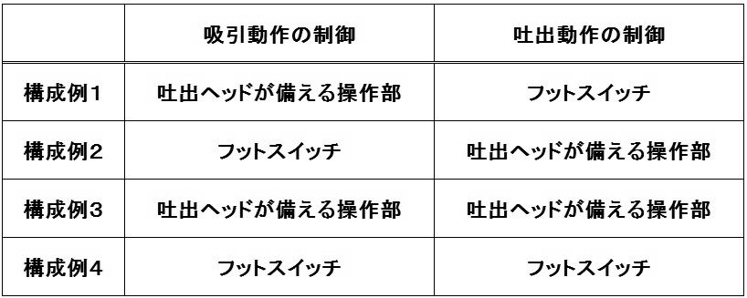
- the controller 20 includes a discharge operation unit that performs ON / OFF control of the discharge operation of the liquid material.
- the discharge operation unit is configured by the foot switch 24 that is electrically connected to the controller 20 via the signal cable. The operator can turn on / off the discharge operation of the liquid material by operating the foot switch 24 with his / her foot. Unlike the present embodiment, it may be configured such that pressurized air having a strength corresponding to the depression amount of the foot switch 24 is supplied to the ejection head 10 to adjust the ejection amount.
- a button, a knob, or the like that functions as a discharge operation unit may be provided in the main body of the controller 20 or the discharge head 10.
- the mechanism described in Patent Document 2 may be employed in the discharge operation unit.
- a method of using the liquid material ejection device 1 according to the first embodiment will be described with reference to FIG. 3 as an example of an operation of attaching a stone (attachment member) S to a workpiece W in a desired pattern.
- the stones S are arranged in a desired pattern on the surface of the workpiece W.
- STEP 2 As shown in FIG. 3 (a), the operator closes the opening 17a of the negative pressure operating portion 17 with a finger so as to generate a suction force at the suction port 15a of the pickup member 15, and the stone to be pasted.
- Pick up S. STEP 3
- FIG. 3 As shown in FIG.
- the pick-up operation of the mounting member S, the application operation of the adhesive L, and the mounting of the mounting member S can be performed without changing the discharge head 10 to another device. Can be carried out. That is, as in the prior art, it is not necessary to use different devices for the pick-up operation and placement operation of the mounting member S and the application operation of the adhesive L. Further, since the distance between the pickup member 15 and the tip end portion of the nozzle 11 is larger than the distance between the pickup member 15 and the base portion of the nozzle 11, the pick-up operation of the mounting member S without being obstructed by the nozzle 11. It is possible to perform the mounting work.
- the attachment member S can be attached after the pattern of the attachment member S is actually arranged and confirmed on the workpiece W, the workability of the operator can be improved.
- the pick-up work device and the application work device are changed twice, the work procedure as in the present invention is performed. Was difficult.
- FIG. 4A is a configuration diagram of the ejection head 10 according to the second embodiment
- FIG. 4B is a configuration diagram of the ejection head 10 according to the third embodiment.
- the second embodiment is different from the first embodiment in that a pickup member 19 having a bent tube 19b is connected to the suction tube 16.
- the third embodiment is different from the second embodiment in that the holder 13 is provided with a suction tube insertion hole so that the body portion 19a of the pickup member 19 and the nozzle 11 are parallel to each other. To do.
- differences will be mainly described, and the same components as those in the first embodiment will be denoted by the same reference numerals in the drawings, and description thereof will be omitted.
- the pickup member 19 of the second embodiment includes a trunk portion 19a and a bent tube 19b extending from the trunk portion 19a.
- the second embodiment is configured such that the distance of the tip portion is wider than the distance between the pickup member 19 and the root portion of the nozzle 11.
- the pickup member 19 of the third embodiment is the same as that of the second embodiment, and only the holder 13 is different.
- the body portion 19a of the pickup member 19 and the nozzle 11 are arranged in parallel.
- the tip of the bent tube 19b is arranged in a direction away from the nozzle 11, the pickup member 19 Compared with the distance of the base part of the nozzle 11, it is comprised so that the distance of a front-end
- the pickup member 19 is arranged so that the suction port 19c is open to the side (front side or depth side in FIG. 4). May be. That is, as shown in FIG. 5, the suction port 19c of the pickup member 19 is disposed at a position (for example, positions a to d in FIG. 5) that is deviated from a straight line R passing through the center of the nozzle 11 and the pickup member 19.
- the pickup member 19 may be arranged as described above.
- the pick-up operation of the attachment member S, the application operation and the attachment of the adhesive L can be performed without changing the ejection head 10 to another device. It becomes possible to carry out the placing work of the member S. Further, as in the first embodiment, the nozzle 11 is not obstructed during the pick-up operation and placement operation of the mounting member S, and the workability can be improved.
Landscapes
- Engineering & Computer Science (AREA)
- Mechanical Engineering (AREA)
- Coating Apparatus (AREA)
- Gripping Jigs, Holding Jigs, And Positioning Jigs (AREA)
Abstract
Description
上記液体材料吐出ヘッドにおいて、前記ピックアップ部材が、先端部に負圧力を発生させて対象物を保持することを特徴としてもよい。
上記液体材料吐出ヘッドにおいて、前記負圧力を調整する負圧操作部を備えることを特徴としてもよい。
上記液体材料吐出ヘッドにおいて、前記液体貯留部および前記ピックアップ部材を着脱自在に保持するホルダーを備えることを特徴としてもよい。
上記液体材料吐出ヘッドにおいて、前記ピックアップ部材の中心軸線と前記ノズルの中心軸線とが、前記ピックアップ部材および前記ノズルの先端に向かって広がるように構成されていることを特徴としてもよい。
上記液体材料吐出ヘッドにおいて、前記液体貯留部に印加する加圧エアのON/OFFを制御する吐出操作部を備えることを特徴としてもよい。
上記液体材料吐出装置において、前記吸引管が、逆流防止機構を備えることを特徴としてもよい。
上記液体材料吐出装置において、前記コントローラから前記加圧管に供給する加圧エアのON/OFFを制御する吐出操作部を備えることを特徴としてもよく、さらに、前記吐出操作部が、前記コントローラと電気的に接続されたフットスイッチであることを特徴としてもよい。
第2の観点に係る本発明の部材取付方法は、上記液体材料吐出装置を用いた部材取付方法であって、前記ノズルからワーク表面に液体材料を塗布し、前記ピックアップ部材で取付部材を保持し、ワーク表面に塗布された液体材料の上に載置することを特徴とする。
以下では図面を参照しながら、実施形態例に係る液体材料吐出装置を説明する。
図1に示すように、第1実施形態例に係る液体材料吐出装置1は、吐出ヘッド10と、コントローラ20と、エアコンプレッサー30とを備えて構成される。この液体材料吐出装置1はハンディ型であり、例えば、ペンダント等のアクセサリーにストーン等のデコレーション用部材(取付部材S)を接着するための接着剤を塗布するために用いられる。
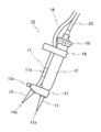
図2に示すように、吐出ヘッド10は、ノズル11と、シリンジ12と、ホルダー13,14と、ピックアップ部材15と、吸引管16と、キャップ部材18とを備えて構成される。
ノズル11は、樹脂または金属製であり、先端部に吐出口11aが設けられている。ノズル11は、吐出口11aの径が異なる複数のノズルの中から、用途に合致するものを選択して採用する。吐出口11aの径は、例えば0.2~2mmである。
シリンジ12は、樹脂または金属製の液体貯留部であり、下端(先端)にノズル11を着脱自在に装着するための連結部を有している。シリンジ12は、容量が異なる複数のシリンジの中から、用途に合致するものを選択して採用する。シリンジ12には、例えばエポキシ接着剤や紫外線硬化樹脂が充填される。シリンジ12の上端(後端)にはつば部が設けられており、つば部にキャップ部材18を装着することができる。
ホルダー14は、シリンジ12が挿通されるシリンジ挿通孔と、吸引管16が挿通される吸引管挿通孔が設けられており、シリンジ12のつば部の近傍を支持する。ホルダー14には、スタンド40のフック部41に係合される貫通孔が設けられている。
本実施形態例では、ホルダー13とホルダー14とを別部材により構成したが、ホルダー13とホルダー14とを一つの部材により構成してもよい。
ノズル11とピックアップ部材15とは、ノズル11の中心軸とピックアップ部材15の中心軸との距離が先端に向かうほど拡がるように配置されている。別の言い方をすれば、ピックアップ部材15とノズル11の根元部分の距離と比べピックアップ部材15とノズル11の先端部分の距離が広がるように、ピックアップ部材15が配置されている。このような構成とすることにより、取付部材Sのピックアップ作業時および載置作業時にノズル11が邪魔しないので、作業性を高めることが可能となっている。
なお、第1実施形態例に係るノズル11およびピックアップ部材15は、樹脂製かつディスポーザブルである。
本実施形態例とは異なり、負圧操作部として、ボタン操作により開口を開閉して負圧を開放する機構を採用し、吸引管16またはホルダー13に配置するようにしてもよい。また、ホルダー14を設けず、キャップ部材18に吸引管挿通孔を設け、キャップ部材18により吸引管16を支持するようにしてもよい。
コントローラ20は、エアコンプレッサー30と連通する加圧エア受入口(不図示)を備えている。加圧エア受入口には、エアコンプレッサー30から加圧エアが供給され、コントローラ20内の圧力調整用レギュレータを介して加圧エア供給口22に所望の加圧力を発生させる。加圧エア供給口22に発生させる加圧力は、加圧調整つまみ26により調整可能である。
なお、フットスイッチ24とは別に、吐出操作部として機能するボタンやつまみ等をコントローラ20の本体或いは吐出ヘッド10に設けるようにしてもよい。例えば特許文献2に記載の機構を吐出操作部に採用してもよい。
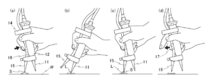
第1実施形態例に係る液体材料吐出装置1の使用方法を、図3を参照しながら、ワークWにストーン(取付部材)Sを所望のパターンで貼り付ける作業の例で説明する。
(STEP1)ワークWの表面に、所望のパターンでストーンSを配置する。
(STEP2)図3(a)に示すように、作業者は、負圧操作部17の開口17aを指で塞ぐことでピックアップ部材15の吸引口15aに吸引力を生じさせ、貼り付け対象のストーンSを拾い上げる。
(STEP3)図3(b)に示すように、ストーンSをピックアップ部材15で保持したまま、拾い上げられたストーンSがあった位置にノズル11の吐出口11aを移動し、フットスイッチ24を操作して接着剤Lを塗布する。ここで、吐出口11aの移動は、手首を傾けることにより簡単に実現することができる。
(STEP4)図3(c)に示すように、作業者は、ピックアップしたストーンSを塗布された接着剤Lの上に載置する。ここで、ストーンSの移動は、手首を傾けることにより簡単に実現することができる。ピックアップ部材15の先端(吸引口15a)でストーンSを押下して、確実に貼り付けが行われるようにしてもよい。
(STEP5)図3(d)に示すように、作業者は、負圧操作部17の開口17aを開放することでピックアップ部材15の吸引力を消失させ、ストーンSの保持を開放する。
また、ピックアップ部材15とノズル11の根元部分の距離と比べピックアップ部材15とノズル11の先端部分の距離が広がるように構成されているので、ノズル11に邪魔されることなく取付部材Sのピックアップ作業および載置作業を行うことが可能である。
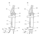
図4(a)は第2実施形態例に係る吐出ヘッド10の構成図、(b)は第3実施形態例に係る吐出ヘッド10の構成図である。第2実施形態例は、屈曲管19bを有するピックアップ部材19が吸引管16に連結されている点で第1実施形態例と相違する。第3実施形態例は、ホルダー13が、ピックアップ部材19の胴部19aとノズル11が平行となる配置関係となるように吸引管挿通孔が設けられている点で、第2実施形態例と相違する。以下では相違点を中心に説明し、第1実施形態例と共通の構成については図中で同一の符号を付し、説明を省略する。
第3実施形態例のピックアップ部材19は、第2実施形態例と同じで、ホルダー13のみが相違する。第3実施形態例では、ピックアップ部材19の胴部19aとノズル11が平行となる配置関係にあるが、屈曲管19bの先端がノズル11から遠ざかる方向に配置されているので、やはりピックアップ部材19とノズル11の根元部分の距離と比べ先端部分の距離が広がるように構成されている。
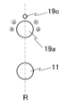
なお、ピックアップ部材19とノズル11の根元部分の距離と比べ先端部分の距離が広がるのであれば、吸引口19cが側方(図4の手前または奥行き側)に開口するようにピックアップ部材19を配置してもよい。すなわち、図5に示すように、ピックアップ部材19の吸引口19cが、ノズル11およびピックアップ部材19の中心を通る直線Rからずれた位置(例えば、図5のa~dの位置)に配置されるようにピックアップ部材19を配置してもよい。
また、第1実施形態例と同様、取付部材Sのピックアップ作業および載置作業時時にノズル11が邪魔することがなく、作業性を高めることが可能とされている。
10 吐出ヘッド
11 ノズル
12 シリンジ(液体貯留部)
13 (下部)ホルダー
14 (上部)ホルダー
15 ピックアップ部材
16 吸引管
17 負圧操作部
18 キャップ部材
19 ピックアップ部材
20 コントローラ
21 負圧エア供給口
22 加圧エア供給口
23 加圧管
24 フットスイッチ
25 負圧調整つまみ
26 加圧調整つまみ
30 エアコンプレッサー
40 スタンド
Claims (13)
- ノズルおよび液体貯留部を備えるハンディ型の液体材料吐出ヘッドにおいて、
前記ノズルと並んで配置された、対象物を保持するピックアップ部材を備えることを特徴とする液体材料吐出ヘッド。 - 前記ピックアップ部材が、先端部に負圧力を発生させて対象物を保持することを特徴とする請求項1に記載の液体材料吐出ヘッド。
- 前記負圧力を調整する負圧操作部を備えることを特徴とする請求項2に記載の液体材料吐出ヘッド。
- 前記液体貯留部および前記ピックアップ部材を着脱自在に保持するホルダーを備えることを特徴とする請求項1ないし3のいずれかに記載の液体材料吐出ヘッド。
- 前記ピックアップ部材が、前記ピックアップ部材および前記ノズルの根元間の距離と比べ先端間の距離が広がるように構成されていることを特徴とする請求項1ないし4のいずれかに記載の液体材料吐出ヘッド。
- 前記ピックアップ部材の中心軸線と前記ノズルの中心軸線とが、前記ピックアップ部材および前記ノズルの先端に向かって広がるように構成されていることを特徴とする請求項1ないし5のいずれかに記載の液体材料吐出ヘッド。
- 前記液体貯留部に印加する加圧エアのON/OFFを制御する吐出操作部を備えることを特徴とする請求項1ないし6のいずれかに記載の液体材料吐出ヘッド。
- 請求項2または3に記載の液体材料吐出ヘッドと、
前記液体貯留部に加圧エアを供給する加圧管と、
前記ピックアップ部材に負圧エアを供給する吸引管と、
加圧管に加圧エアを供給し、吸引管に負圧エアを供給するコントローラと、を備える液体材料吐出装置。 - 前記吸引管が、逆流防止機構を備えることを特徴とする請求項8に記載の液体材料吐出装置。
- 前記コントローラから前記加圧管に供給する加圧エアのON/OFFを制御する吐出操作部を備えることを特徴とする請求項8または9に記載の液体材料吐出装置。
- 前記吐出操作部が、前記コントローラと電気的に接続されたフットスイッチであることを特徴とする請求項10に記載の液体材料吐出装置。
- 請求項8ないし11のいずれかに記載の液体材料吐出装置を用いた部材取付方法であって、
前記ピックアップ部材で取付部材を保持し、
前記ピックアップ部材で取付部材を保持したまま前記ノズルからワーク表面に液体材料を塗布し、
ワーク表面に塗布された液体材料の上に前記ピックアップ部材が保持する取付部材を載置する部材取付方法。 - 請求項8ないし11のいずれかに記載の液体材料吐出装置を用いた部材取付方法であって、
前記ノズルからワーク表面に液体材料を塗布し、
前記ピックアップ部材で取付部材を保持し、ワーク表面に塗布された液体材料の上に載置する部材取付方法。
Priority Applications (3)
| Application Number | Priority Date | Filing Date | Title |
|---|---|---|---|
| CN201980016969.9A CN111801169A (zh) | 2018-03-03 | 2019-02-28 | 具备拾起构件的吐出头及液体材料吐出装置 |
| KR1020207025885A KR102611161B1 (ko) | 2018-03-03 | 2019-02-28 | 픽업 부재를 구비하는 토출 헤드 및 액체 재료 토출 장치 |
| EP19763164.1A EP3763445B1 (en) | 2018-03-03 | 2019-02-28 | Discharge head with pickup member, and liquid-material discharge device |
Applications Claiming Priority (2)
| Application Number | Priority Date | Filing Date | Title |
|---|---|---|---|
| JP2018038115A JP7002127B2 (ja) | 2018-03-03 | 2018-03-03 | ピックアップ部材を備える吐出ヘッドおよび液体材料吐出装置 |
| JP2018-038115 | 2018-03-03 |
Publications (1)
| Publication Number | Publication Date |
|---|---|
| WO2019172090A1 true WO2019172090A1 (ja) | 2019-09-12 |
Family
ID=67846112
Family Applications (1)
| Application Number | Title | Priority Date | Filing Date |
|---|---|---|---|
| PCT/JP2019/007927 Ceased WO2019172090A1 (ja) | 2018-03-03 | 2019-02-28 | ピックアップ部材を備える吐出ヘッドおよび液体材料吐出装置 |
Country Status (6)
| Country | Link |
|---|---|
| EP (1) | EP3763445B1 (ja) |
| JP (1) | JP7002127B2 (ja) |
| KR (1) | KR102611161B1 (ja) |
| CN (1) | CN111801169A (ja) |
| TW (1) | TWI794426B (ja) |
| WO (1) | WO2019172090A1 (ja) |
Cited By (1)
| Publication number | Priority date | Publication date | Assignee | Title |
|---|---|---|---|---|
| CN113134802A (zh) * | 2020-01-17 | 2021-07-20 | 鸿富锦精密电子(成都)有限公司 | 拧取治具及采用该拧取治具的点胶机构 |
Citations (6)
| Publication number | Priority date | Publication date | Assignee | Title |
|---|---|---|---|---|
| JPS6441171U (ja) * | 1987-09-07 | 1989-03-13 | ||
| JPH07237149A (ja) * | 1994-02-28 | 1995-09-12 | Sekisui Chem Co Ltd | 自動釘打機および自動釘打機による釘打ち方法 |
| JP2003080142A (ja) | 2001-09-06 | 2003-03-18 | Musashi Eng Co Ltd | 液体吐出制御用手動スイッチ装置および液体吐出システム |
| JP2003182293A (ja) | 2001-12-25 | 2003-07-03 | Makiko Tami | 工芸品及び工芸品の作成方法 |
| JP2015017151A (ja) * | 2013-07-09 | 2015-01-29 | アムテック株式会社 | 洗浄剤組成物 |
| JP2017154058A (ja) * | 2016-02-29 | 2017-09-07 | 株式会社吉野工業所 | 塗布具 |
Family Cites Families (9)
| Publication number | Priority date | Publication date | Assignee | Title |
|---|---|---|---|---|
| JP3080258B2 (ja) * | 1992-02-27 | 2000-08-21 | スズキ株式会社 | ワーク搬送用治具 |
| JP2002505169A (ja) * | 1998-03-06 | 2002-02-19 | バクスター・インターナショナル・インコーポレイテッド | 組織シーラントアプリケーターのための乱流混合ヘッドおよびそれのためのスプレーヘッド |
| JP2002086748A (ja) * | 2000-09-13 | 2002-03-26 | Ricoh Co Ltd | サブタンクとインク供給装置及びインクジェット記録装置 |
| CN201832766U (zh) * | 2010-10-09 | 2011-05-18 | 罗世椿 | 手动止回柱塞点胶阀 |
| TWM431838U (en) * | 2012-03-02 | 2012-06-21 | Yu-Hong Lin | Glass repairing device |
| US9688458B1 (en) * | 2013-05-31 | 2017-06-27 | Hasbro, Inc. | Folding portable craft gun with storage for plunger rod |
| KR101381362B1 (ko) * | 2013-09-30 | 2014-04-04 | 구광석 | 진공을 이용한 제품 운반장치 |
| CN105578377A (zh) * | 2016-03-03 | 2016-05-11 | 东莞市纳声电子设备科技有限公司 | 一种微型扬声器双磁路磁性组装自动化设备及其生产工艺 |
| CN206789531U (zh) * | 2017-05-22 | 2017-12-22 | 无锡芯坤电子科技有限公司 | 一种新型芯片真空吸笔 |
-
2018
- 2018-03-03 JP JP2018038115A patent/JP7002127B2/ja active Active
-
2019
- 2019-02-28 CN CN201980016969.9A patent/CN111801169A/zh active Pending
- 2019-02-28 KR KR1020207025885A patent/KR102611161B1/ko active Active
- 2019-02-28 EP EP19763164.1A patent/EP3763445B1/en active Active
- 2019-02-28 WO PCT/JP2019/007927 patent/WO2019172090A1/ja not_active Ceased
- 2019-03-04 TW TW108107089A patent/TWI794426B/zh active
Patent Citations (6)
| Publication number | Priority date | Publication date | Assignee | Title |
|---|---|---|---|---|
| JPS6441171U (ja) * | 1987-09-07 | 1989-03-13 | ||
| JPH07237149A (ja) * | 1994-02-28 | 1995-09-12 | Sekisui Chem Co Ltd | 自動釘打機および自動釘打機による釘打ち方法 |
| JP2003080142A (ja) | 2001-09-06 | 2003-03-18 | Musashi Eng Co Ltd | 液体吐出制御用手動スイッチ装置および液体吐出システム |
| JP2003182293A (ja) | 2001-12-25 | 2003-07-03 | Makiko Tami | 工芸品及び工芸品の作成方法 |
| JP2015017151A (ja) * | 2013-07-09 | 2015-01-29 | アムテック株式会社 | 洗浄剤組成物 |
| JP2017154058A (ja) * | 2016-02-29 | 2017-09-07 | 株式会社吉野工業所 | 塗布具 |
Non-Patent Citations (1)
| Title |
|---|
| See also references of EP3763445A4 |
Cited By (1)
| Publication number | Priority date | Publication date | Assignee | Title |
|---|---|---|---|---|
| CN113134802A (zh) * | 2020-01-17 | 2021-07-20 | 鸿富锦精密电子(成都)有限公司 | 拧取治具及采用该拧取治具的点胶机构 |
Also Published As
| Publication number | Publication date |
|---|---|
| KR102611161B1 (ko) | 2023-12-06 |
| TW201938274A (zh) | 2019-10-01 |
| KR20200124690A (ko) | 2020-11-03 |
| JP2019150772A (ja) | 2019-09-12 |
| CN111801169A (zh) | 2020-10-20 |
| TWI794426B (zh) | 2023-03-01 |
| EP3763445A1 (en) | 2021-01-13 |
| EP3763445B1 (en) | 2025-04-02 |
| JP7002127B2 (ja) | 2022-01-20 |
| EP3763445A4 (en) | 2021-12-01 |
Similar Documents
| Publication | Publication Date | Title |
|---|---|---|
| EP1825827A3 (en) | Water jet unit and handheld device for cleaning gums and teeth | |
| US4035919A (en) | Direct bonding bracket positioning and mounting tool | |
| MY139264A (en) | Insertion tool for ocular implant and method for using same | |
| US6820768B2 (en) | Elongate hand held glue gun | |
| US5356292A (en) | Dental sandblasting confiner | |
| WO2019172090A1 (ja) | ピックアップ部材を備える吐出ヘッドおよび液体材料吐出装置 | |
| MXPA03004664A (es) | Guia personalizada para colocar brackets ortodonticos y metodos de fabricacion y uso de los mismos. | |
| JPH01110359A (ja) | 歯科用化粧張り器具 | |
| US20120061488A1 (en) | Hands-Free Directable Low-Pressure Air Source and Method for Cosmetology Use | |
| TW200612883A (en) | Counter pressure device for ophthalmic drug delivery | |
| NL9400968A (nl) | Inrichting voor het aanbrengen van een tandheelkundig hulpmiddel op ten minste één tand van ten minste één rij tanden. | |
| HK40030465A (en) | Discharge head with pickup member, and liquid-material discharge device | |
| KR101666066B1 (ko) | 밴드타입 글루 속눈썹 연장 작업 보조 장치 | |
| EP3310245B1 (en) | New dental suction-mirror tool | |
| KR102167656B1 (ko) | 치과기공용 조각도 세트 | |
| EP2349072B1 (en) | Dental restoration conditioning apparatus and method | |
| ES2699834T3 (es) | Soporte de tuerca para instrumento de perforación corporal | |
| US20050282103A1 (en) | Air injector having dental mirror mount | |
| WO2004069023A3 (en) | Vacuum holder for juxtaposing body tissues | |
| JPH08266956A (ja) | 超軽量構造ハンドスプレーガン | |
| JP3239678U (ja) | 人の皮膚に描画を施すための交換ユニット | |
| JP3234467U (ja) | 蝋受け皿 | |
| JP2019150772A5 (ja) | ||
| CN217091121U (zh) | 一种可防止夹持物位移的泪道镊子 | |
| KR200352837Y1 (ko) | 다이아몬드 스킨 필링기 |
Legal Events
| Date | Code | Title | Description |
|---|---|---|---|
| 121 | Ep: the epo has been informed by wipo that ep was designated in this application |
Ref document number: 19763164 Country of ref document: EP Kind code of ref document: A1 |
|
| NENP | Non-entry into the national phase |
Ref country code: DE |
|
| ENP | Entry into the national phase |
Ref document number: 20207025885 Country of ref document: KR Kind code of ref document: A |
|
| ENP | Entry into the national phase |
Ref document number: 2019763164 Country of ref document: EP Effective date: 20201005 |
|
| WWG | Wipo information: grant in national office |
Ref document number: 2019763164 Country of ref document: EP |