WO2019172189A1 - 内視鏡用アプリケータ装置 - Google Patents
内視鏡用アプリケータ装置 Download PDFInfo
- Publication number
- WO2019172189A1 WO2019172189A1 PCT/JP2019/008428 JP2019008428W WO2019172189A1 WO 2019172189 A1 WO2019172189 A1 WO 2019172189A1 JP 2019008428 W JP2019008428 W JP 2019008428W WO 2019172189 A1 WO2019172189 A1 WO 2019172189A1
- Authority
- WO
- WIPO (PCT)
- Prior art keywords
- applicator
- light
- endoscope
- light emitting
- body cavity
- Prior art date
- Legal status (The legal status is an assumption and is not a legal conclusion. Google has not performed a legal analysis and makes no representation as to the accuracy of the status listed.)
- Ceased
Links
Images




Classifications
-
- A—HUMAN NECESSITIES
- A61—MEDICAL OR VETERINARY SCIENCE; HYGIENE
- A61B—DIAGNOSIS; SURGERY; IDENTIFICATION
- A61B1/00—Instruments for performing medical examinations of the interior of cavities or tubes of the body by visual or photographical inspection, e.g. endoscopes; Illuminating arrangements therefor
- A61B1/00064—Constructional details of the endoscope body
- A61B1/00071—Insertion part of the endoscope body
- A61B1/0008—Insertion part of the endoscope body characterised by distal tip features
- A61B1/00089—Hoods
-
- A—HUMAN NECESSITIES
- A61—MEDICAL OR VETERINARY SCIENCE; HYGIENE
- A61B—DIAGNOSIS; SURGERY; IDENTIFICATION
- A61B1/00—Instruments for performing medical examinations of the interior of cavities or tubes of the body by visual or photographical inspection, e.g. endoscopes; Illuminating arrangements therefor
- A61B1/00002—Operational features of endoscopes
- A61B1/00004—Operational features of endoscopes characterised by electronic signal processing
- A61B1/00009—Operational features of endoscopes characterised by electronic signal processing of image signals during a use of endoscope
-
- A—HUMAN NECESSITIES
- A61—MEDICAL OR VETERINARY SCIENCE; HYGIENE
- A61B—DIAGNOSIS; SURGERY; IDENTIFICATION
- A61B1/00—Instruments for performing medical examinations of the interior of cavities or tubes of the body by visual or photographical inspection, e.g. endoscopes; Illuminating arrangements therefor
- A61B1/00002—Operational features of endoscopes
- A61B1/00043—Operational features of endoscopes provided with output arrangements
- A61B1/00045—Display arrangement
-
- A—HUMAN NECESSITIES
- A61—MEDICAL OR VETERINARY SCIENCE; HYGIENE
- A61B—DIAGNOSIS; SURGERY; IDENTIFICATION
- A61B1/00—Instruments for performing medical examinations of the interior of cavities or tubes of the body by visual or photographical inspection, e.g. endoscopes; Illuminating arrangements therefor
- A61B1/00064—Constructional details of the endoscope body
- A61B1/00071—Insertion part of the endoscope body
- A61B1/0008—Insertion part of the endoscope body characterised by distal tip features
- A61B1/00101—Insertion part of the endoscope body characterised by distal tip features the distal tip features being detachable
-
- A—HUMAN NECESSITIES
- A61—MEDICAL OR VETERINARY SCIENCE; HYGIENE
- A61B—DIAGNOSIS; SURGERY; IDENTIFICATION
- A61B1/00—Instruments for performing medical examinations of the interior of cavities or tubes of the body by visual or photographical inspection, e.g. endoscopes; Illuminating arrangements therefor
- A61B1/012—Instruments for performing medical examinations of the interior of cavities or tubes of the body by visual or photographical inspection, e.g. endoscopes; Illuminating arrangements therefor characterised by internal passages or accessories therefor
- A61B1/018—Instruments for performing medical examinations of the interior of cavities or tubes of the body by visual or photographical inspection, e.g. endoscopes; Illuminating arrangements therefor characterised by internal passages or accessories therefor for receiving instruments
-
- A—HUMAN NECESSITIES
- A61—MEDICAL OR VETERINARY SCIENCE; HYGIENE
- A61B—DIAGNOSIS; SURGERY; IDENTIFICATION
- A61B1/00—Instruments for performing medical examinations of the interior of cavities or tubes of the body by visual or photographical inspection, e.g. endoscopes; Illuminating arrangements therefor
- A61B1/04—Instruments for performing medical examinations of the interior of cavities or tubes of the body by visual or photographical inspection, e.g. endoscopes; Illuminating arrangements therefor combined with photographic or television appliances
- A61B1/043—Instruments for performing medical examinations of the interior of cavities or tubes of the body by visual or photographical inspection, e.g. endoscopes; Illuminating arrangements therefor combined with photographic or television appliances for fluorescence imaging
-
- A—HUMAN NECESSITIES
- A61—MEDICAL OR VETERINARY SCIENCE; HYGIENE
- A61B—DIAGNOSIS; SURGERY; IDENTIFICATION
- A61B1/00—Instruments for performing medical examinations of the interior of cavities or tubes of the body by visual or photographical inspection, e.g. endoscopes; Illuminating arrangements therefor
- A61B1/06—Instruments for performing medical examinations of the interior of cavities or tubes of the body by visual or photographical inspection, e.g. endoscopes; Illuminating arrangements therefor with illuminating arrangements
- A61B1/0607—Instruments for performing medical examinations of the interior of cavities or tubes of the body by visual or photographical inspection, e.g. endoscopes; Illuminating arrangements therefor with illuminating arrangements for annular illumination
-
- A—HUMAN NECESSITIES
- A61—MEDICAL OR VETERINARY SCIENCE; HYGIENE
- A61B—DIAGNOSIS; SURGERY; IDENTIFICATION
- A61B1/00—Instruments for performing medical examinations of the interior of cavities or tubes of the body by visual or photographical inspection, e.g. endoscopes; Illuminating arrangements therefor
- A61B1/06—Instruments for performing medical examinations of the interior of cavities or tubes of the body by visual or photographical inspection, e.g. endoscopes; Illuminating arrangements therefor with illuminating arrangements
- A61B1/0646—Instruments for performing medical examinations of the interior of cavities or tubes of the body by visual or photographical inspection, e.g. endoscopes; Illuminating arrangements therefor with illuminating arrangements with illumination filters
-
- A—HUMAN NECESSITIES
- A61—MEDICAL OR VETERINARY SCIENCE; HYGIENE
- A61B—DIAGNOSIS; SURGERY; IDENTIFICATION
- A61B1/00—Instruments for performing medical examinations of the interior of cavities or tubes of the body by visual or photographical inspection, e.g. endoscopes; Illuminating arrangements therefor
- A61B1/06—Instruments for performing medical examinations of the interior of cavities or tubes of the body by visual or photographical inspection, e.g. endoscopes; Illuminating arrangements therefor with illuminating arrangements
- A61B1/0661—Endoscope light sources
- A61B1/0676—Endoscope light sources at distal tip of an endoscope
-
- A—HUMAN NECESSITIES
- A61—MEDICAL OR VETERINARY SCIENCE; HYGIENE
- A61B—DIAGNOSIS; SURGERY; IDENTIFICATION
- A61B1/00—Instruments for performing medical examinations of the interior of cavities or tubes of the body by visual or photographical inspection, e.g. endoscopes; Illuminating arrangements therefor
- A61B1/06—Instruments for performing medical examinations of the interior of cavities or tubes of the body by visual or photographical inspection, e.g. endoscopes; Illuminating arrangements therefor with illuminating arrangements
- A61B1/0661—Endoscope light sources
- A61B1/0684—Endoscope light sources using light emitting diodes [LED]
-
- A—HUMAN NECESSITIES
- A61—MEDICAL OR VETERINARY SCIENCE; HYGIENE
- A61N—ELECTROTHERAPY; MAGNETOTHERAPY; RADIATION THERAPY; ULTRASOUND THERAPY
- A61N5/00—Radiation therapy
- A61N5/06—Radiation therapy using light
- A61N5/0601—Apparatus for use inside the body
- A61N5/0603—Apparatus for use inside the body for treatment of body cavities
-
- A—HUMAN NECESSITIES
- A61—MEDICAL OR VETERINARY SCIENCE; HYGIENE
- A61N—ELECTROTHERAPY; MAGNETOTHERAPY; RADIATION THERAPY; ULTRASOUND THERAPY
- A61N5/00—Radiation therapy
- A61N5/06—Radiation therapy using light
- A61N5/0613—Apparatus adapted for a specific treatment
- A61N5/062—Photodynamic therapy, i.e. excitation of an agent
-
- A—HUMAN NECESSITIES
- A61—MEDICAL OR VETERINARY SCIENCE; HYGIENE
- A61N—ELECTROTHERAPY; MAGNETOTHERAPY; RADIATION THERAPY; ULTRASOUND THERAPY
- A61N5/00—Radiation therapy
- A61N5/06—Radiation therapy using light
- A61N2005/0626—Monitoring, verifying, controlling systems and methods
-
- A—HUMAN NECESSITIES
- A61—MEDICAL OR VETERINARY SCIENCE; HYGIENE
- A61N—ELECTROTHERAPY; MAGNETOTHERAPY; RADIATION THERAPY; ULTRASOUND THERAPY
- A61N5/00—Radiation therapy
- A61N5/06—Radiation therapy using light
- A61N2005/063—Radiation therapy using light comprising light transmitting means, e.g. optical fibres
-
- A—HUMAN NECESSITIES
- A61—MEDICAL OR VETERINARY SCIENCE; HYGIENE
- A61N—ELECTROTHERAPY; MAGNETOTHERAPY; RADIATION THERAPY; ULTRASOUND THERAPY
- A61N5/00—Radiation therapy
- A61N5/06—Radiation therapy using light
- A61N2005/065—Light sources therefor
- A61N2005/0651—Diodes
- A61N2005/0652—Arrays of diodes
Definitions
- the present invention relates to an endoscope applicator device, and more particularly to an endoscope applicator device applicable to an endoscope system for performing endoscopic treatment.
- Patent Document 1 discloses a hooded endoscope in which an optical fiber is projected from a forceps opening opened at a distal end portion of an insertion portion of an endoscope, and excitation laser light can be irradiated into a body cavity.
- Patent Document 2 an overtube is attached to a distal end hood of an insertion portion of an endoscope, and an electronic laser that can emit excitation laser light into a body cavity through an optical fiber disposed in the overtube.
- An endoscope is disclosed.
- Patent Document 1 since the forceps port of the endoscope is used for laser light irradiation, the optical fiber occupies the forceps port during that time, and the treatment tool through the forceps port in the endoscope is used. Cannot be used. In addition, since an operation of inserting and removing the optical fiber and the treatment tool into and from the endoscope occurs during laser light irradiation and treatment, the operation related to the use of the endoscope becomes complicated, and the work takes time. Cost.
- Patent Document 2 since it is necessary to attach both the tip hood and the overtube to the endoscope, the configuration of the endoscope becomes complicated and the operation becomes complicated.
- This invention is made
- An applicator device for an endoscope is an applicator device for an endoscope including an applicator that can be attached to and detached from an insertion portion of an endoscope that is inserted into a body cavity.
- the light emitting element which irradiates the excitation light for exciting and acting the photosensitive substance administered to the affected part of the biological tissue of this is provided.
- the light emitting element mentioned above which concerns on this aspect is multiply arranged along the circumferential direction of an applicator.
- the applicator described above according to this aspect includes a flow path for administering a photosensitive substance to a living tissue in a body cavity.
- the endoscope according to this aspect includes an illumination unit that illuminates the body cavity with illumination light, a light receiving unit that receives light from inside the body cavity, and a forceps port through which the treatment tool inserted through the insertion unit enters and exits. At the tip of the part.
- the above-described applicator according to this aspect includes an optical filter that reduces or blocks at least the excitation light by covering the light receiving unit. Further, the above-described applicator according to this aspect includes a filter adjustment unit that performs adjustment of a reduction amount of excitation light using an optical filter, or switching between the presence and absence of excitation light shielding.
- an endoscope system including the above-described endoscope according to this aspect includes a light source device that generates illumination light and guides the illumination light to an illuminating unit, and an image that is captured based on light received from the light receiving unit. And a monitor device that is electrically connected to the processor device and displays an observation image generated by the processor device.
- the endoscopic applicator device supplies power to the light emitting element and is connected to the processor device.
- the power supply device further includes an electrically connected power supply device, and control means for attenuating or blocking an output signal related to excitation light from the processor device to the monitor device when the light emitting element is powered from the power supply device.
- the applicator mentioned above which concerns on this aspect is a front-end
- the above-described photosensitive substance according to this aspect is a light-emitting probe, and the light-emitting element emits excitation light for exciting the light-emitting probe administered to the affected part of the biological tissue in the body cavity to emit light. To do.
- the supply start means starts supplying the luminescent probe and the irradiation start means starts irradiating excitation light, and the presence or absence of a residual diseased part in the living tissue is determined based on the result of luminescence observation of the luminescent probe by light reception from the light receiving part. Determination means.
- the above-described light emitting probe according to this embodiment is a fluorescent probe.
- the above-described light emitting element according to this aspect irradiates excitation light for exciting a photosensitive substance accumulated in an affected part of a living tissue in a body cavity and imparting an injury caused by a photochemical reaction to the affected part.
- the above-described light emitting element according to this aspect is a light emitting diode.
- endoscopic treatment can be performed smoothly.
- FIG. 1 is a schematic view of an endoscope system to which an endoscope applicator device according to an embodiment of the present invention is applied. It is a front view which shows the front-end
- FIG. 5 is a cross-sectional view taken along line AA in FIG. 4.
- FIG. 1 is a schematic view of an endoscope system 2 to which an endoscope applicator device 1 (hereinafter, also simply referred to as an applicator device 1) according to the present embodiment is applied.
- the endoscope system 2 includes an endoscope 4, a light source device 6 that is electrically and optically connected to the endoscope 4, a processor device 8 that is electrically connected to the endoscope 4, and a processor device. 8 and a monitor device 10 electrically connected by a cable 14, and an air / water supply tank 12 in which air and water supplied to the endoscope 4 are stored.
- the endoscope 4 extends from the operation unit 18, a flexible insertion unit 16 that is inserted into the body cavity of the subject, an operation unit 18 that is coupled to a proximal end portion of the insertion unit 16, and the operation unit 18.
- the universal cord 20 includes a cord (not shown) that electrically connects the operation unit 18 to the light source device 6 and the processor device 8.
- the air / water supply tube 22 is provided to send air or water from the air / water supply tank 12 toward the operation unit 18, and a part of the air / water supply tube 22 is built in the universal cord 20.
- FIG. 2 shows a front view of the distal end portion 24 in the insertion portion 16 of the endoscope 4.
- two illumination portions 26 that illuminate the inside of the body cavity with illumination light
- a light receiving portion 28 that receives light from inside the body cavity
- a forceps port 32 through which a treatment tool 30 such as forceps inserted through the insertion portion 16 enters and exits.
- an air / water supply port 34 for supplying air / water into the body cavity.
- An air / water supply channel for supplying air and water from 12 is provided.
- the illumination unit 26 irradiates the illumination light generated by the light source device 6 into the body cavity from the distal end portion 24 through an optical fiber (not shown) inserted through the operation unit 18 and the insertion unit 16.
- the light receiving unit 28 includes an objective lens, an image sensor, and the like (not shown), and acquires information on a captured image to be observed by receiving light from the body cavity.
- the light source device 6 includes a light source (not shown) such as a xenon lamp or a halogen lamp, and generates illumination light by the light source based on the operation of the operation unit 18 or the like. This illumination light is, for example, white light, and is guided to each illumination unit 26 of the distal end portion 24 through the universal cord 20, the operation unit 18, and the insertion unit 16 in this order.
- the light source device 6 may be another light source.
- the processor device 8 processes the information of the captured image acquired by the light receiving unit 28 based on the operation of the operation unit 18 to generate an observation image, and transmits the observation image to the monitor device 10 via the cable 14.
- the monitor device 10 displays an observation image generated by the processor device. Note that the monitor device 10 may be provided with an input unit (not shown) that allows input of observation image display settings and the like.
- the operation unit 18 includes an angle knob 36 for bending the distal end portion 24 of the insertion unit 16 in a three-dimensional manner, and various types of buttons, such as an illumination button 38a, an air / water supply button 38b, and an imaging button 38c.
- buttons such as an illumination button 38a, an air / water supply button 38b, and an imaging button 38c.
- an operation button 38 and an insertion port 40 of the treatment instrument 30 By operating the illumination button 38a, the illumination light generated by the light source device 6 can be irradiated into the body cavity from each illumination unit 26 through the universal cord 20, the operation unit 18, and the insertion unit 16 in this order.
- the air or water in the air / water supply tank 12 is passed through the air / water supply tube 34, the universal cord 20, the operation unit 18 and the insertion unit 16 in this order from the air / water supply port 34 into the body cavity. Can be injected.
- the imaging button 38c By operating the imaging button 38c, the information of the captured image acquired by the light receiving unit 28 can be transmitted to the processor device 8 through the insertion unit 16, the operation unit 18, and the universal code 20 in this order.
- the displayed observation image can be enlarged or reduced. Further, by operating the treatment tool 30 protruding from the insertion port 40, it is possible to treat the affected part in the body cavity.
- the operation unit 18 controls the illumination unit 26 and the light receiving unit 28, operates the treatment tool 30 inserted / extracted at the forceps port 32, and supplies / feeds water from the air / water supply port 34.
- Various operations, control and operations can be performed collectively.
- the endoscope 4 and the endoscope system 2 described so far are not special and expensive special specifications that have a high-sensitivity CCD camera or the like and can perform fluorescence observation. It is of a normal specification that can be observed and treated in a body cavity, and is relatively inexpensive.
- the applicator device 1 can be separately attached to the endoscope 4 and the endoscope system 2 having the normal specifications described above.
- the applicator device 1 includes an applicator 42 detachably attached to the distal end portion 24 of the endoscope 4, a power supply device 44, a control circuit (control means) 46, and a probe tank 48. And.
- the power supply device 44 is electrically connected to the applicator 42 and the processor device 8 via cables 50 and 52, respectively.
- the power supply device 44 is provided with a power switch 54 that can supply power to the applicator 42 via the cable 50.
- the control circuit 46 is electrically interposed in a cable 52 between the power supply device 44 and the processor device 8.
- the probe tank 48 stores a fluorescent probe (light emitting probe, photosensitive substance) to be supplied to the applicator 42, and is connected to the applicator 42 via a probe tube bundle 56. Further, the probe tank 48 is provided with a supply switch 58 for starting to supply the fluorescent probe to the applicator 42 via the probe tube bundle 56.
- a fluorescent probe light emitting probe, photosensitive substance
- the fluorescent probe of the present embodiment is a fluorescent substance that reacts specifically with a predetermined enzyme that is excessively expressed on the affected surface of a living tissue, for example, the surface of a cancer cell membrane, and significantly increases fluorescence, although the initial state is non-fluorescent It is.
- This fluorescent probe emits green fluorescence by irradiating excitation light with a predetermined excitation wavelength. Furthermore, this fluorescent probe has excellent cell membrane permeability.
- the applicator 42 is connected with an adjustment wire 60 of an optical filter 68 described later.
- the cable 50, the probe tube bundle 56, and the adjustment wire 60 are collectively connected to the end face 42b of the applicator 42 by a single universal cord 62 formed by consolidating them, as shown in FIG. Is done.
- FIG. 3 is a perspective view showing a state before the applicator 42 is attached to the distal end portion 24 of the endoscope 4.
- FIG. 4 is a perspective view showing a state after the applicator 42 is attached to the distal end portion 24 of the endoscope 4.
- the applicator 42 has, for example, a cylindrical shape and is formed of a flexible resin that can be easily attached to and detached from the distal end portion 24.
- it is preferably made of a transparent resin, for example, a silicone resin.
- the applicator 42 is also used as a so-called tip hood, and is attached to the tip portion 24 to prevent damage to the living tissue due to contact of the tip portion 24 in the body cavity during endoscopic diagnosis. Is possible.
- the applicator 42 also plays a role of ensuring an appropriate distance between the distal end portion 24 and the living tissue to be observed, appropriate illumination by each illumination unit 26 in the body cavity, and appropriate imaging by the light receiving unit 28. Is possible.
- a large number of LED chips (light emitting elements, light emitting diodes) 64 are provided along the circumferential direction on the distal end surface 42a of the applicator 42 located on the distal end portion 24 side of the endoscope 4.
- a large number of channels 66 are opened along the circumferential direction of the tip surface 42a on the outer peripheral side of each LED chip 64 on the tip surface 42a.
- Each channel 66 is formed so as to penetrate the outer peripheral portion 42c of the applicator 42 from the tip surface 42a to the end surface 42b opposite to the tip surface 42a in the cylinder height direction of the applicator 42.
- Respective probe tubes (not shown) constituting the probe tube bundle 56 arranged inside the universal cord 62 are connected to the openings of the flow paths 66 in the end face 42b.
- the fluorescent probe is administered from the probe tank 48 through the probe tube bundle 56 to the living tissue in the body cavity from the opening of each flow channel 66.
- the opening of each flow channel 66 is narrowed like a nozzle, so that the fluorescent probe is uniformly sprayed toward the living tissue.
- the LED chip 64 is a minimum one that can irradiate high-intensity light, and irradiates excitation light for exciting the fluorescent probe to cause fluorescence.
- the excitation light emitted from the LED chip 64 is, for example, blue light having a predetermined excitation wavelength (for example, about 488 nm or more).
- a predetermined excitation wavelength for example, about 488 nm or more.
- the fluorescent probe reacts with the affected area, it is excited by the above-described excitation light, and generates green fluorescence with extremely high fluorescence intensity (about 350 times before the reaction) at a predetermined excitation wavelength (for example, about 525 nm). This green fluorescence is suitable for identifying an affected area because it can be easily distinguished from a living tissue or bleeding during treatment in fluorescence observation.
- the applicator 42 of this embodiment includes an optical filter 68.
- the optical filter 68 is an excitation light cut filter, and is formed in a range that covers the light receiving unit 28 from the distal end surface 42 a of the applicator 42 toward the center in the cylinder radial direction of the applicator 42.
- the optical filter 68 includes an optical element 70, a cover portion 72 that houses the optical element 70, and the above-described adjustment wire 60 (see FIG. 1) partially incorporated in the universal cord 62.
- the adjustment wire 60 is connected to the optical element 70.
- the optical element 70 is formed of, for example, a film-like glass material whose surface is laminated and coated, has flexibility, and does not transmit the excitation light having the above-described predetermined excitation wavelength, or has a performance difficult to transmit. For this reason, the optical element 70 attenuates or blocks the excitation light received by the light receiving unit 28, whereby the fluorescence generated by the fluorescent probe can be received more clearly by the light receiving unit 28, and high-precision fluorescence observation It can be performed.
- the optical filter 68 is preferably a so-called long pass filter.
- FIG. 5 is a cross-sectional view taken along the line AA in FIG.
- the treatment tool 30 is not shown in a cross section, and a part of the configuration is not shown for the sake of explanation or ease of understanding.
- the cover portion 72 of the optical filter 68 is integrally formed with the applicator 42 using, for example, the same resin as that of the applicator 42.
- the optical element 70 is movably accommodated along the height direction.
- the adjustment wire 60 has one end connected to the optical element 70 and the other end inserted through the outer peripheral portion of the applicator 42 and protruding from the end surface 42b of the applicator 42 via the universal cord 62.
- the adjustment wire 60 is operated by inserting and removing from the applicator 42 outside the applicator 42.
- the optical filter 68 is caused to function when the optical element 70 is advanced to a position covering the light receiving unit 28, while the optical filter 68 is not allowed to function when the optical element 70 is retracted to a position where the light receiving unit 28 is exposed. Thereby, in the optical filter 68, adjustment of the light reduction amount of excitation light or switching of the presence or absence of shielding of excitation light is performed (filter adjustment means).
- the control circuit 46 performs control to attenuate or block the output signal of the excitation light from the processor device 8 to the monitor device 10 when power supply to each LED chip 64 is started from the power supply device 44. Specifically, the information of the captured image acquired by the light receiving unit 28 is transmitted to the processor device 8 via the universal code 20. Since the cable 14 connects the processor device 8 and the monitor device 10 with so-called RGB terminals, the information of the captured image is analog data of R (red), G (green), and B (blue) in the processor device 8. The signal is decomposed and transmitted to the monitor device 10.
- control circuit 46 When the control circuit 46 receives a signal indicating that the power switch 54 is turned on via the cable 52, the control circuit 46 outputs a signal of excitation light that is blue light output from the processor device 8 to the monitor device 10, that is, from the B terminal of the processor device 8. Attenuate or block output signal. In this way, the control circuit 46 connected to the power supply device 44 is connected to the processor device 8 of the endoscope system 2 by the cable 52, so that the excitation light signal control system 74 is provided to the existing endoscope system 2. Is possible.
- the affected part 80 such as cancer cells existing in the living tissue 78 in the body cavity 76 is excised by the treatment tool 30 extending from the forceps port 32, and FIG. It is assumed that after the retraction in the arrow direction, the remaining affected part 84 still exists inside the excision surface 82 of the biological tissue 78 after excision.
- the supply switch 58 of the probe tank 48 is turned on (supply start means).
- the fluorescent probe is supplied from the probe tank 48 to the respective flow paths 66 through the probe tube bundle 56, and the fluorescent probes 86 (indicated by broken line arrows) are opened from the openings of the respective flow paths 66 to the excision surface 82 of the biological tissue 78. Sprayed evenly. Since the fluorescent probe 86 has excellent cell membrane permeability, it penetrates from the excision surface 82 of the biological tissue 78 into the remaining affected area 84 and selectively reacts with the remaining affected area 84.
- the power switch 54 of the power supply device 44 is turned on (irradiation start means).
- power is supplied from the power supply device 44 to each LED chip 64 via the cable 50, and excitation light 88 (indicated by a one-dot chain line arrow) is emitted from each LED chip 64.
- the fluorescent probe 86 that has reacted with the remaining affected part 84 is excited by the excitation light 88 to generate fluorescence 90 (indicated by a two-dot chain line arrow).
- a captured image obtained as a result of receiving the fluorescence 90 by the light receiving unit 28 is processed into an observation image by the processor device 8 and transmitted to the monitor 10. By observing this observation image with fluorescence, the presence or absence of the remaining affected part 84 can be easily determined (determination means).
- the applicator device 1 is configured as a device in which only functions specialized for fluorescence observation are integrated, and the forceps port 32 is restricted by uses other than the use of the treatment instrument 30. There is no. Specifically, in the fluorescence observation and the subsequent treatment, it is not necessary to attach / detach the treatment tool 30 from the endoscope 4 or attach / detach the insertion portion 16 of the endoscope 4 from the body cavity. Thus, since the applicator device 1 does not hinder the basic functions of the endoscope system 2 and the endoscope 4, endoscopic treatment when performing fluorescence observation can be performed smoothly.
- an affected part is treated by submucosal dissection (ESD method) using the endoscope 4
- ESD method submucosal dissection
- a resected section is pathologically determined, cancer cell invasion is determined, and cancer cell residue is determined.
- ESD method submucosal dissection
- treatment, fluorescence observation, next treatment policy determination, and re-treatment can all be performed quickly during one endoscopic operation. Therefore, endoscopic treatment when performing fluorescence observation can be performed more smoothly.
- the applicator 42 provided with each LED chip 64 is detachably provided at the distal end portion 24 of the insertion portion 16 of the endoscope 4, thereby irradiating excitation light from each LED chip 64 of the applicator 42. Therefore, it is not necessary to project an optical fiber for irradiating the excitation laser beam from the forceps port 32, an overtube or the like for disposing the optical fiber is unnecessary, and an expensive laser beam is used. An irradiation device is also unnecessary.
- the fluorescent probe in the fluorescence observation, it is possible to excite the fluorescent probe with a simple structure and inexpensively to make it fluorescent.
- the brightness of the LED chip 64 has been improved, and the fluorescent probe of the present embodiment can obtain extremely high fluorescence intensity even with low-power excitation light, so that the applicator 42 for the endoscope 4 can be used.
- the LED chip 64 There is a history of applying the LED chip 64 as a light source of excitation light.
- the fluorescence generated in the affected area can be excited uniformly by high illuminance, so that a clearer observation image can be obtained.
- the forceps port 32 need not be used to administer the fluorescent probe.
- the fluorescent probe can be uniformly sprayed on the affected part by opening a large number of the flow paths 66 along the circumferential direction of the applicator 42, the presence or absence of the affected part can be determined more efficiently.
- optical filter 68 is provided in the applicator 42, a clear observation image that effectively eliminates the influence of the excitation light even if the processor device 8 is not equipped with sophisticated and expensive image processing software. Can be generated and displayed on the monitor 10.
- the optical element 70 is made movable by the adjustment wire 60, it is possible to easily adjust the light reduction amount of the excitation light by the optical filter 68 or switch the presence / absence of shielding of the excitation light. By performing such filter adjustment, it is possible to obtain a clear observation image in which the influence of the excitation light is more effectively eliminated according to the usage state of the applicator device 1.
- the applicator device 1 since the applicator device 1 includes the power supply device 44 and the control circuit 46, the excitation light signal control system 74 independent of the endoscope system 2 can be provided.
- the excitation light signal control system 74 complements the function of the optical filter 68 and is a system specialized for fluorescence observation. Therefore, even if the processor device 8 is not equipped with sophisticated and expensive image processing software, it is possible to display a clear observation image that effectively eliminates the influence of the excitation light on the monitor device 10.
- the LED chip 64 and the flow channel 66 are not limited to the distal end surface 42 a of the applicator 42, and may be arranged and opened on the outer peripheral portion 42 c of the applicator 42.
- the excitation light can be irradiated over a wider range in the body cavity by each LED chip 64, and the fluorescent probe can be sprayed uniformly over a wider range in the body cavity from each channel 66.
- the LED chips 64 and the flow paths 66 are arranged and opened so as to have different annular arrangements along the circumferential direction of the outer peripheral portion 42c.
- the outer peripheral portion 42c may be formed in a step shape, and the LED chips 64 and the flow paths 66 may be arranged and opened so as to have different annular arrays along the circumferential direction.
- each LED chip 64 it is also possible to dispose each LED chip 64 by mounting each LED chip 64 on a sheet-like flexible substrate (not shown) and attaching the flexible substrate to the applicator 42. Further, the numbers of the LED chips 64 and the channels 66 are not particularly limited, and at least one of the LED chips 64 and the channels 66 may be formed on the applicator 42.
- filter adjustment means other than the mechanism using the adjustment wire 60 of the above-described embodiment may be used as long as the adjustment of the light reduction amount of the excitation light or the switching of whether or not the excitation light is blocked.
- the power switch 54 and the supply switch 58 described in the above embodiment may be arranged in the operation unit 18 of the endoscope 4 so as to be operable together with the operation of the operation unit 18. Thereby, the operativity of the applicator apparatus 1 can further be improved.
- the excitation light signal control system 74 complements the function of the optical filter 68 described above. Therefore, the excitation light signal control system 74 is not necessarily provided as long as the excitation light can be sufficiently reduced or blocked by the optical filter 68 alone. Further, instead of providing the optical filter 68, it is possible to provide only the excitation light signal control system 74. Further, the excitation light signal control system 74 may be constructed by interposing the control circuit 46 in the cable 14 connecting the processor device 8 and the monitor device 10.
- the control circuit 46 is unnecessary, and the electrical connection between the power supply device 44 and the processor device 8 is also unnecessary. Therefore, when the excitation light signal control system 74 is not provided, a simpler power supply means to each LED chip 64, for example, a small battery that can supply power to each LED chip 64 by charging, is used instead of the power supply device 44. 42 may be incorporated. Thereby, the applicator device 1 having more excellent portability can be realized.
- the applicator 42 is also used as a cylindrical tip hood.
- the shape of the applicator 42 is not limited to this, as long as at least the LED chip 64, preferably the flow channel 66 is formed, and the function of the applicator 42 can be realized without impeding the function of the endoscope 4.
- the attachment is not limited to the above, and may be an attachment attached to the insertion portion 16 for use.
- the fluorescent probe is not limited to the one described in the above embodiment, and the applicator device 1 can use a wide range of luminescent probes including phosphorescent probes other than fluorescent probes. In this case, light emission observation including phosphorescence as well as fluorescence can be easily performed.
- the applicator 42 can be used for PDT (photodynamic therapy).
- PDT is a treatment method in which a photosensitive substance having a tumor affinity is administered to a living body, and then the affected part is irradiated with excitation light to selectively damage only the affected part such as cancer cells to be destroyed.
- each LED chip 64 irradiates the excitation light for exciting the photosensitive substance accumulated in the affected part of the living tissue in the body cavity and imparting the injury to the affected part by the photochemical reaction.
- a drug containing a photosensitive substance is injected into a blood vessel and administered to a living body.
- a light emitting diode other than the LED chip 64 such as an organic EL, may be provided in the applicator 42 as a light emitting element.
Landscapes
- Health & Medical Sciences (AREA)
- Life Sciences & Earth Sciences (AREA)
- Surgery (AREA)
- Engineering & Computer Science (AREA)
- Biomedical Technology (AREA)
- Animal Behavior & Ethology (AREA)
- General Health & Medical Sciences (AREA)
- Pathology (AREA)
- Radiology & Medical Imaging (AREA)
- Nuclear Medicine, Radiotherapy & Molecular Imaging (AREA)
- Veterinary Medicine (AREA)
- Public Health (AREA)
- Optics & Photonics (AREA)
- Biophysics (AREA)
- Physics & Mathematics (AREA)
- Heart & Thoracic Surgery (AREA)
- Molecular Biology (AREA)
- Medical Informatics (AREA)
- Microelectronics & Electronic Packaging (AREA)
- Signal Processing (AREA)
- Endoscopes (AREA)
Abstract
内視鏡用アプリケータ装置(1)は、体腔内に挿入される内視鏡(4)の挿入部(16)に着脱可能なアプリケータ(42)を含み、アプリケータ(42)は、体腔内の生体組織の患部に投与した光感受性物質を励起して作用させるための励起光を照射する発光素子(64)を備える。
Description
本発明は、内視鏡用アプリケータ装置に関し、特に内視鏡治療を行う内視鏡システムに適用可能な内視鏡用アプリケータ装置に関する。
特許文献1には、内視鏡の挿入部の先端部に開口された鉗子口から光ファイバを突出させ、励起用レーザ光を体腔内に照射可能とするフード付き内視鏡が開示されている。
また、特許文献2には、内視鏡の挿入部の先端フードにオーバーチューブを装着し、オーバーチューブに配設された光ファイバを介して励起用レーザ光を体腔内に照射可能とする電子内視鏡が開示されている。
また、特許文献2には、内視鏡の挿入部の先端フードにオーバーチューブを装着し、オーバーチューブに配設された光ファイバを介して励起用レーザ光を体腔内に照射可能とする電子内視鏡が開示されている。
しかしながら、特許文献1においては、内視鏡の鉗子口をレーザ光照射のために利用しているため、その間は光ファイバが鉗子口を占有し、内視鏡において鉗子口を介した処置具の使用ができない。また、レーザ光照射のときと処置時とにおいて、内視鏡に光ファイバと処置具とを抜き差しして切り換える作業が発生するため、内視鏡の使用に係る操作が煩雑になり、作業に時間を要する。
また、特許文献2においては、内視鏡に、先端フードとオーバーチューブとの双方を装着する必要があるため、内視鏡の構成が複雑となるとともに、作業が煩雑となる。
本発明は、このような課題に鑑みてなされたもので、内視鏡治療を円滑に行うことができる内視鏡用アプリケータ装置を提供することを目的とする。
本発明は、このような課題に鑑みてなされたもので、内視鏡治療を円滑に行うことができる内視鏡用アプリケータ装置を提供することを目的とする。
本発明は以下の態様として実現することができる。
本態様に係る内視鏡用アプリケータ装置は、体腔内に挿入される内視鏡の挿入部に着脱可能なアプリケータを含む内視鏡用アプリケータ装置であって、アプリケータは、体腔内の生体組織の患部に投与した光感受性物質を励起して作用させるための励起光を照射する発光素子を備える。
本態様に係る内視鏡用アプリケータ装置は、体腔内に挿入される内視鏡の挿入部に着脱可能なアプリケータを含む内視鏡用アプリケータ装置であって、アプリケータは、体腔内の生体組織の患部に投与した光感受性物質を励起して作用させるための励起光を照射する発光素子を備える。
また、本態様に係る前述した発光素子は、アプリケータの周方向に沿って複数配置される。
また、本態様に係る前述したアプリケータは、光感受性物質を体腔内の生体組織に投与する流路を備える。
また、本態様に係る前述したアプリケータは、光感受性物質を体腔内の生体組織に投与する流路を備える。
また、本態様に係る前述した流路は、アプリケータの周方向に沿って複数開口される。
また、本態様に係る前述した内視鏡は、体腔内を照明光により照光する照光部と、体腔内から受光する受光部と、挿入部に挿通された処置具が入出する鉗子口とを挿入部の先端部に有する。
また、本態様に係る前述した内視鏡は、体腔内を照明光により照光する照光部と、体腔内から受光する受光部と、挿入部に挿通された処置具が入出する鉗子口とを挿入部の先端部に有する。
また、本態様に係る前述したアプリケータは、受光部を覆うことにより少なくとも励起光を減光又は遮光する光学フィルタを備える。
また、本態様に係る前述したアプリケータは、光学フィルタによる励起光の減光量の調整、又は励起光の遮光の有無の切り換えを行うフィルタ調整手段を有する。
また、本態様に係る前述したアプリケータは、光学フィルタによる励起光の減光量の調整、又は励起光の遮光の有無の切り換えを行うフィルタ調整手段を有する。
また、本態様に係る前述した内視鏡を含む内視鏡システムは、照明光を生成して照光部に導光する光源装置と、受光部からの受光に基づく撮像画像を処理して観察画像を生成するプロセッサ装置と、プロセッサ装置と電気的に接続され、プロセッサ装置で生成した観察画像を表示するモニタ装置とを備え、内視鏡用アプリケータ装置は、発光素子に給電するとともにプロセッサ装置に電気的に接続される電源装置と、電源装置から発光素子に給電したとき、プロセッサ装置からモニタ装置への励起光に関する出力信号を減衰又は遮断する制御手段とをさらに備える。
また、本態様に係る前述したアプリケータは、挿入部の先端部に装着される先端フードである。
また、本態様に係る前述した光感受性物質は、発光プローブであって、発光素子は、アプリケータにより体腔内の生体組織の患部に投与した発光プローブを励起して発光させるための励起光を照射する。
また、本態様に係る前述した光感受性物質は、発光プローブであって、発光素子は、アプリケータにより体腔内の生体組織の患部に投与した発光プローブを励起して発光させるための励起光を照射する。
また、本態様に係る前述した流路を介して発光プローブを供給開始する供給開始手段と、発光素子から励起光を照射開始する照射開始手段と、処置具により生体組織における患部を処置した後、供給開始手段による発光プローブの供給開始、及び照射開始手段による励起光の照射開始を行い、受光部からの受光による発光プローブの発光観察の結果に基づいて、生体組織における残留患部の有無を判定する判定手段とを備える。
また、本態様に係る前述した発光プローブは、蛍光プローブである。
また、本態様に係る前述した発光素子は、体腔内の生体組織の患部に蓄積させた光感受性物質を励起して患部に光化学反応による傷害を付与するための励起光を照射する。
また、本態様に係る前述した発光素子は、発光ダイオードである。
また、本態様に係る前述した発光素子は、体腔内の生体組織の患部に蓄積させた光感受性物質を励起して患部に光化学反応による傷害を付与するための励起光を照射する。
また、本態様に係る前述した発光素子は、発光ダイオードである。
本発明の前述した内視鏡用アプリケータ装置の態様によれば、内視鏡治療を円滑に行うことができる。
以下、図面に基づき本発明の一実施形態に係る内視鏡用アプリケータ装置について説明する。
図1は、本実施形態の内視鏡用アプリケータ装置1(以下、単にアプリケータ装置1ともいう)が適用される内視鏡システム2の概略図を示す。内視鏡システム2は、内視鏡4と、内視鏡4と電気的及び光学的に接続される光源装置6と、内視鏡4と電気的に接続されるプロセッサ装置8と、プロセッサ装置8とケーブル14で電気的に接続されるモニタ装置10と、内視鏡4に供給する空気や水が貯留される送気送水タンク12とを備える。
図1は、本実施形態の内視鏡用アプリケータ装置1(以下、単にアプリケータ装置1ともいう)が適用される内視鏡システム2の概略図を示す。内視鏡システム2は、内視鏡4と、内視鏡4と電気的及び光学的に接続される光源装置6と、内視鏡4と電気的に接続されるプロセッサ装置8と、プロセッサ装置8とケーブル14で電気的に接続されるモニタ装置10と、内視鏡4に供給する空気や水が貯留される送気送水タンク12とを備える。
内視鏡4は、被検者の体腔内に挿入される可撓性を有した挿入部16と、挿入部16の基端部分に結合された操作部18と、操作部18から延設されるユニバーサルコード20及び送気送水チューブ22とを備える。ユニバーサルコード20には、操作部18と光源装置6及びプロセッサ装置8とをそれぞれ電気的に接続する図示しないコードが内蔵されている。送気送水チューブ22は、送気送水タンク12から操作部18に向けて空気や水を送るために設けられ、ユニバーサルコード20には、送気送水チューブ22の一部は内蔵されている。
図2は、内視鏡4の挿入部16における先端部24の正面図を示す。先端部24には、体腔内を照明光により照光する2つの照光部26と、体腔内から受光する受光部28と、挿入部16に挿通された鉗子等の処置具30が入出する鉗子口32と、体腔内に送気送水するための送気送水口34とが形成されている。
図1に示す挿入部16及び操作部18の内部には、何れも図示しないが、鉗子口32に向けて処置具30が挿入される鉗子チャンネル、送気送水口34に向けて送気送水タンク12から空気や水を流す送気送水チャンネルが設けられている。照光部26は、光源装置6で生成した照明光を操作部18及び挿入部16に挿通される図示しない光ファイバを介して先端部24から体腔内に照明光を照射する。
受光部28は、図示しない対物レンズや撮像素子等を備え、体腔内から受光することにより観察対象の撮像画像の情報を取得する。光源装置6は、例えばキセノンランプやハロゲンランプ等の図示しない光源を備え、操作部18の操作等に基づき、光源により照明光を生成する。この照明光は、例えば白色光であって、ユニバーサルコード20、操作部18、挿入部16を順に介して先端部24の各照光部26に導光される。なお、光源装置6はその他の光源であっても良い。
プロセッサ装置8は、操作部18の操作等に基づき、受光部28により取得された撮像画像の情報を処理して観察画像を生成し、ケーブル14を介してモニタ装置10に伝送する。モニタ装置10は、プロセッサ装置で生成した観察画像を表示する。なお、モニタ装置10に、観察画像の表示設定等の入力が可能な図示しない入力部を設けても良い。
図1に示すように、操作部18には、挿入部16の先端部24を三次元的に湾曲させるためのアングルノブ36と、照光ボタン38a、送気送水ボタン38b、撮像ボタン38c等の各種の操作ボタン38と、処置具30の挿入口40とが設けられている。照光ボタン38aを操作することにより、光源装置6で生成した照明光をユニバーサルコード20、操作部18、挿入部16を順に介して各照光部26から体腔内に照射可能である。
送気送水ボタン38bを操作することにより、送気送水タンク12の空気や水を送気送水チューブ22、ユニバーサルコード20、操作部18、挿入部16を順に介して送気送水口34から体腔内に噴射可能である。撮像ボタン38cを操作することにより、受光部28で取得した撮像画像の情報を挿入部16、操作部18、ユニバーサルコード20を順に介してプロセッサ装置8に伝送可能であり、また、モニタ装置10に表示された観察画像の拡大縮小可能である。また、挿入口40から突出した処置具30を操作することにより体腔内の患部の処置が可能となる。
このように、操作部18では、照光部26及び受光部28に係る制御、鉗子口32にて入出される処置具30の操作、送気送水口34からの送気送水等の先端部24における各種の操作及び制御や操作を一括して行うことができる。なお、これまで説明した内視鏡4及び内視鏡システム2は、高感度CCDカメラ等を有して蛍光観察を行うことができるような特殊で高価な専用仕様のものではなく、一般的な体腔内観察及び治療が可能な通常仕様のものであって、比較的安価なものである。
ここで、本実施形態のアプリケータ装置1は、前述した通常仕様の内視鏡4及び内視鏡システム2に別途後から装着して使用することができる。図1に示すように、アプリケータ装置1は、内視鏡4の先端部24に着脱可能に装着されるアプリケータ42と、電源装置44と、制御回路(制御手段)46と、プローブタンク48とを備えている。
電源装置44は、アプリケータ42及びプロセッサ装置8にそれぞれケーブル50、52を介して電気的に接続される。また、電源装置44には、ケーブル50を介してアプリケータ42側に給電可能な電源スイッチ54が設けられている。制御回路46は、電源装置44とプロセッサ装置8との間のケーブル52において電気的に介在される。
プローブタンク48は、アプリケータ42に供給する蛍光プローブ(発光プローブ、光感受性物質)が貯留され、アプリケータ42にプローブチューブ束56を介して接続されている。また、プローブタンク48には、蛍光プローブをプローブチューブ束56を介してアプリケータ42側に供給開始する供給スイッチ58が設けられている。
本実施形態の蛍光プローブは、初期状態は無蛍光であるものの、生体組織の患部、例えば癌細胞の膜表面に過剰に発現する所定の酵素と特異に反応し、蛍光が大幅に増大する蛍光物質である。この蛍光プローブは、所定の励起波長の励起光を照射することにより、緑色の蛍光を発生する。さらに、この蛍光プローブは、優れた細胞膜透過性を有している。
また、アプリケータ42には、後述する光学フィルタ68の調整ワイヤ60が接続されている。好ましくは、ケーブル50、プローブチューブ束56、及び調整ワイヤ60は、図1に示すように、これらを内部に集約して形成した1つのユニバーサルコード62によってアプリケータ42の端面42bに一括して接続される。
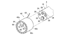
図3は、内視鏡4の先端部24にアプリケータ42を装着する前の状態の斜視図を示す。また、図4は、内視鏡4の先端部24にアプリケータ42を装着した後の状態の斜視図を示す。アプリケータ42は、例えば、筒状を呈し、先端部24への着脱が容易な柔軟性がある樹脂から形成されている。また、内視鏡4の通常使用時やアプリケータ装置1による蛍光観察時における光学的な影響を極力排除するために、好ましくは透明樹脂から形成され、例えばシリコーン樹脂等から形成されている。
図4に示すように、アプリケータ42は、先端部24に装着した状態において、少なくとも各照光部26、鉗子口32、及び送気送水口34が体腔内に露出可能である。このため、アプリケータ42を先端部24に装着した状態においても、鉗子口32から処置具30の入出が可能であり、内視鏡4のその他の機能も制約を受けることはない。
また、本実施形態のアプリケータ42は、いわゆる先端フードとしても兼用され、先端部24に装着することにより内視鏡診断時に体腔内における先端部24の接触によって生体組織が損傷等することを阻止可能である。また、アプリケータ42は、先端部24と観察対象である生体組織との適切な距離を確保する役割をも担い、体腔内における各照光部26による適切な照光、及び受光部28による適切な撮像を可能とする。
ここで、内視鏡4の先端部24側に位置するアプリケータ42の先端面42aには、その周方向に沿って多数のLEDチップ(発光素子、発光ダイオード)64が設けられている。また、先端面42aにおける各LEDチップ64の外周側には、先端面42aの周方向に沿って多数の流路66が開口されている。
各流路66は、先端面42aから、アプリケータ42の筒高さ方向における先端面42aと反対側の端面42bに至るまでアプリケータ42の外周部42cを貫通して形成されている。端面42bにおける各流路66の開口には、ユニバーサルコード62の内部に配置されたプローブチューブ束56を構成する図示しない各プローブチューブがそれぞれ接続される。
プローブタンク48の供給スイッチ58をオンにすることにより、蛍光プローブは、プローブタンク48からプローブチューブ束56を介して各流路66の開口から体腔内の生体組織に投与される。好ましくは、各流路66の開口はノズル状に狭められており、これにより蛍光プローブは生体組織に向けて満遍なく噴霧される。
LEDチップ64は、高輝度光を照射可能な極小のものであって、蛍光プローブを励起して蛍光させるための励起光を照射する。LEDチップ64から照射される励起光は、例えば、所定の励起波長(例えば約488nm以上)を有する青色光である。蛍光プローブは、患部と反応すると、前述した励起光により励起され、所定の励起波長(例えば約525nm)においては蛍光強度が極度に大きな(反応前の350倍程度)の緑色の蛍光を発生する。この緑色蛍光は、蛍光観察において生体組織や処置の際の出血等と判別が容易であるため、患部の特定に好適である。
さらに、本実施形態のアプリケータ42は、光学フィルタ68を備えている。光学フィルタ68は、励起光カットフィルタであって、図4に示すように、アプリケータ42の先端面42aからアプリケータ42の筒径方向中心に向けて受光部28を覆う範囲に形成されている。光学フィルタ68は、光学素子70、光学素子70を収納するカバー部72、及び、ユニバーサルコード62に一部が内蔵された前述の調整ワイヤ60(図1参照)を備える。調整ワイヤ60は光学素子70に接続されている。
光学素子70は、例えば、表面をラミネートコーティングしたフィルム状の硝子材から形成されて可撓性を有し、前述した所定の励起波長を有する励起光を透過しない、或いは透過し難く性能を有する。このため、光学素子70が受光部28で受光する励起光を減光又は遮光し、これにより、蛍光プローブが発生する蛍光をより鮮明に受光部28で受光することができ、高精度な蛍光観察を行うことができる。なお、一般に、蛍光波長は励起波長よりも長いため、光学フィルタ68はいわゆるロングパスフィルタであるのが好ましい。
図5は、図4のA-A矢視断面図である。なお、図5においては、処置具30は断面で示しておらず、また、説明上或いは分かり易さの関係上、一部の構成は図示していない。光学フィルタ68のカバー部72は、例えば、アプリケータ42と同様の樹脂でアプリケータ42と一体成形され、光学素子70の外周部を部分的に保持しながら、アプリケータ42の筒径方向及び筒高さ方向に沿って光学素子70を移動可能に収容している。
調整ワイヤ60は、一端が光学素子70に接続され、他端がアプリケータ42の外周部を挿通されてアプリケータ42の端面42bからユニバーサルコード62を経て突出している。調整ワイヤ60をアプリケータ42の外部においてアプリケータ42に対し抜き差しして操作する。
光学素子70が受光部28を覆う位置に前進されたときには光学フィルタ68を機能させ、一方、光学素子70が受光部28を露出させる位置に退行されたときには光学フィルタ68の機能をさせない。これにより、光学フィルタ68において、励起光の減光量の調整、又は励起光の遮光の有無の切り換えが行われる(フィルタ調整手段)。
制御回路46は、各LEDチップ64に電源装置44から給電が開始されると、プロセッサ装置8からモニタ装置10への励起光の出力信号を減衰又は遮断する制御を行う。具体的には、受光部28で取得した撮像画像の情報は、プロセッサ装置8にユニバーサルコード20を介して伝送される。ケーブル14はプロセッサ装置8及びモニタ装置10をいわゆるRGB端子で接続しているため、撮像画像の情報は、プロセッサ装置8においてR(赤)、G(緑)、B(青)の3色のアナログ信号に分解され、モニタ装置10に伝送される。
制御回路46は、ケーブル52を介して電源スイッチ54がオンの信号を受けると、プロセッサ装置8からモニタ装置10に出力される青色光である励起光の信号、すなわちプロセッサ装置8のB端子からの出力信号を減衰又は遮断する。このように、内視鏡システム2のプロセッサ装置8に、電源装置44に接続した制御回路46をケーブル52で接続することにより、既存の内視鏡システム2にいわば励起光信号制御システム74を提供することが可能である。
以下、図5を参照して、内視鏡システム2へのアプリケータ装置1の適用例について説明する。先ず、内視鏡システム2を操作部18において操作することにより、体腔76内の生体組織78に存在していた癌細胞等の患部80を鉗子口32から延びる処置具30によって切除し、図5の矢印方向に退避させた後、切除後の生体組織78の切除面82の内側に未だ残留患部84が存在していた場合を想定する。
このような前提のもと、次に、内視鏡システム2に予め装備したアプリケータ装置1において、プローブタンク48の供給スイッチ58をオンにする(供給開始手段)。これにより、プローブタンク48からプローブチューブ束56を介して各流路66に蛍光プローブが供給され、生体組織78の切除面82に各流路66の開口から蛍光プローブ86(破線矢印で示す)が万遍なく噴霧される。蛍光プローブ86は、優れた細胞膜透過性を有するため、生体組織78の切除面82から残留患部84に浸透し、残留患部84と選択的に反応する。
次に、電源装置44の電源スイッチ54をオンにする(照射開始手段)。これにより、電源装置44からケーブル50を介して各LEDチップ64に給電され、各LEDチップ64から励起光88(一点鎖線矢印で示す)が照射される。残留患部84と反応した蛍光プローブ86は、励起光88により励起されて蛍光90(二点鎖線矢印で示す)を発生する。この蛍光90を受光部28で受光した結果得られた撮像画像がプロセッサ装置8で観察画像に処理されてモニタ10に伝送される。この観察画像を蛍光観察することにより残留患部84の有無を容易に判定することができる(判定手段)。
以上のように、本実施形態のアプリケータ装置1は、蛍光観察に特化した機能のみを集約した装置として構成しており、鉗子口32が処置具30の使用以外の用途で制約を受けることはない。具体的には、蛍光観察及びその後の処置において、内視鏡4からの処置具30の着脱や、体腔内からの内視鏡4の挿入部16の着脱は不要である。このように、アプリケータ装置1が内視鏡システム2及び内視鏡4の基本機能を阻害しないことにより、蛍光観察を行う際の内視鏡治療を円滑に行うことができる。
また、例えば、内視鏡4による粘膜下層剥離術(ESD法)により患部を処置した場合、従来は、切除切片を病理判断し、癌細胞の浸潤判定を行い、癌細胞の残留が判定されたときには、別の日に改めて内視鏡手術を行う必要があった。しかし、アプリケータ装置1を内視鏡システム2に適用することにより、一度の内視鏡手術中に、処置、蛍光観察、次の治療方針決定、再処置をすべて迅速に行うことができる。従って、蛍光観察を行う際の内視鏡治療をさらに円滑に行うことができる。
より詳しくは、各LEDチップ64を設けたアプリケータ42を内視鏡4の挿入部16の先端部24に着脱可能に設けたことにより、アプリケータ42の各LEDチップ64から励起光を照射することができるため、励起用レーザ光を照射するための光ファイバを鉗子口32から突出させなくとも良いし、光ファイバを配設するためのオーバーチューブ等は不要であり、また、高価なレーザ光照射装置も不要である。
従って、蛍光観察において、簡単な構成で且つ安価に蛍光プローブを励起して蛍光させることが可能である。なお、昨今、LEDチップ64の輝度は向上し、さらに本実施形態の蛍光プローブは、低出力の励起光でも極度に大きな蛍光強度を得ることができるため、内視鏡4用のアプリケータ42に励起光の光源としてLEDチップ64を適用した経緯がある。
また、LEDチップ64をアプリケータ42の周方向に沿って多数配置することにより、患部において発生する蛍光を高照度により満遍なく励起させることができるため、より鮮明な観察画像を得ることができる。
また、アプリケータ42に蛍光プローブを投与するための流路66を設けたことにより、蛍光プローブを投与するために鉗子口32を使用しなくとも良い。また、例えば、処置後に蛍光観察を行いたい場合に、治療用のスコープに加え、蛍光プローブを供給するためのチューブを体腔内に挿入するような方法を採用しなくとも良いため、患者の負担を大幅に低減することもできる。
また、流路66をアプリケータ42の周方向に沿って多数開口することにより、患部に蛍光プローブを満遍なく噴霧することができるため、より効率的に患部の有無を判定することができる。
また、アプリケータ42に光学フィルタ68を設けたことにより、プロセッサ装置8に高度な且つ高価な画像処理のソフトウエアが搭載されていなくとも、励起光による影響を効果的に排除した鮮明な観察画像を生成し、モニタ10に表示することができる。
また、調整ワイヤ60により光学素子70を可動式にしたことにより、光学フィルタ68による励起光の減光量の調整、又は励起光の遮光の有無の切り換えを容易に行うことができる。このようなフィルタ調整を行うことにより、アプリケータ装置1の使用状況に応じて、励起光による影響をより効果的に排除した鮮明な観察画像を得ることができる。
また、アプリケータ装置1は、電源装置44及び制御回路46を備えているため、内視鏡システム2とは独立した励起光信号制御システム74を提供することができる。この励起光信号制御システム74は、光学フィルタ68の機能を補完するものであるとともに、蛍光観察に特化したシステムである。従って、プロセッサ装置8に高度な且つ高価な画像処理のソフトウエアが搭載されていなくとも、モニタ装置10に励起光による影響を効果的に排除した鮮明な観察画像を表示することができる。
以上で本発明の一実施形態についての説明を終えるが、本発明は上記実施形態に限定されるものではなく、本発明の趣旨を逸脱しない範囲で種々の変更ができるものである。
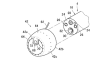
例えば、図6に示すように、LEDチップ64及び流路66は、アプリケータ42の先端面42aに限らず、アプリケータ42の外周部42cに配置、開口しても良い。これにより、各LEDチップ64によって励起光を体腔内のより広範囲に亘って照射することができ、また、各流路66から蛍光プローブを体腔内のより広範囲に亘って満遍なく噴霧することができる。
例えば、図6に示すように、LEDチップ64及び流路66は、アプリケータ42の先端面42aに限らず、アプリケータ42の外周部42cに配置、開口しても良い。これにより、各LEDチップ64によって励起光を体腔内のより広範囲に亘って照射することができ、また、各流路66から蛍光プローブを体腔内のより広範囲に亘って満遍なく噴霧することができる。
この場合には、図6に示すように、各LEDチップ64及び各流路66を外周部42cの周方向に沿ってそれぞれ別の環状配列となるように配置、開口するのが好ましい。これにより、各LEDチップ64による励起光の照射、及び各流路66からの蛍光プローブの噴霧を互いに干渉しないで行うことができる。また、外周部42cを段差状に形成して各LEDチップ64及び各流路66を周方向に沿ってそれぞれ別の環状配列となるように配置、開口しても良い。
また、各LEDチップ64を図示しないシート状のフレキシブル基板上に実装し、このフレキシブル基板をアプリケータ42に貼り付けることにより各LEDチップ64を配置することも可能である。また、LEDチップ64及び流路66の数は、特に限定されるものではなく、それぞれ少なくとも1つがアプリケータ42に形成されれば良い。
また、励起光の減光量の調整、又は励起光の遮光の有無の切り換えが可能であれば、上記実施形態の調整ワイヤ60を用いた機構以外のフィルタ調整手段を用いても良い。
また、上記実施形態で説明した電源スイッチ54及び供給スイッチ58は、内視鏡4の操作部18に配置して操作部18の操作とともに操作可能に構成しても良い。これにより、アプリケータ装置1の操作性をさらに向上することができる。
また、上記実施形態で説明した電源スイッチ54及び供給スイッチ58は、内視鏡4の操作部18に配置して操作部18の操作とともに操作可能に構成しても良い。これにより、アプリケータ装置1の操作性をさらに向上することができる。
また、励起光信号制御システム74は、前述した光学フィルタ68の機能を補完するものである。従って、光学フィルタ68のみで励起光を十分に減光又は遮光可能であれば、励起光信号制御システム74は必ずしも設けなくとも良い。また、光学フィルタ68を設けない代わりに励起光信号制御システム74のみを設けることも可能である。また、プロセッサ装置8とモニタ装置10とを接続するケーブル14に制御回路46を介在させて励起光信号制御システム74を構築しても良い。
また、励起光信号制御システム74を設けない場合には、制御回路46は不要であり、電源装置44とプロセッサ装置8との電気的な接続も不要である。従って、励起光信号制御システム74を設けない場合には、電源装置44の代わりに各LEDチップ64へのさらなる簡素な給電手段、例えば充電により各LEDチップ64に給電可能な小型バッテリ等をアプリケータ42に内蔵しても良い。これにより、より携帯性に優れたアプリケータ装置1を実現することができる。
また、上記実施形態では、アプリケータ42は筒状を呈した先端フードとして兼用されている。しかし、これに限らず、少なくともLEDチップ64、好ましくはさらに流路66が形成され、内視鏡4の機能を阻害しないでアプリケータ42の機能を実現可能であれば、このアプリケータ42の形状に限定されるものではなく、挿入部16に取り付けて使用するアタッチメント等であっても良い。
また、蛍光プローブは、上記実施形態で説明したものに限定されるものではなく、また、アプリケータ装置1には蛍光プローブ以外の燐光プローブを含む広い範囲に亘る発光プローブを使用可能である。この場合に、蛍光に限らず燐光を含む発光観察を簡便に行うことができる。
また、図7に示すように、各LEDチップ64のみを配置し、各流路66を有さないアプリケータ42を形成しても良い。この場合には、アプリケータ42をPDT(光線力学治療)に用いることができる。PDTとは、腫瘍親和性を有する光感受性物質を生体に投与した後、患部に励起光を照射し、癌細胞等の患部のみに選択的に傷害を付与して破壊する治療法である。
この場合には、各LEDチップ64は、体腔内の生体組織の患部に蓄積させた光感受性物質を励起して患部に光化学反応による傷害を付与するための励起光を照射する。PDTでは、各流路66から蛍光プローブを含む発光プローブを体腔内に噴霧する代わりに、光感受性物質を含む薬剤を血管に注射等して生体に投与する。
また、LEDチップ64以外の発光ダイオード、例えば有機EL等を発光素子としてアプリケータ42に設けても良い。
1 内視鏡用アプリケータ装置
2 内視鏡システム
4 内視鏡
6 光源装置
8 プロセッサ装置
10 モニタ装置
16 挿入部
24 先端部
26 照光部
28 受光部
30 処置具
32 鉗子口
42 アプリケータ
44 電源装置
46 制御回路(制御手段)
54 電源スイッチ(照射開始手段)
58 供給スイッチ(供給開始手段)
60 調整ワイヤ(フィルタ調整手段)
64 LEDチップ(発光素子、発光ダイオード)
66 流路
68 光学フィルタ
2 内視鏡システム
4 内視鏡
6 光源装置
8 プロセッサ装置
10 モニタ装置
16 挿入部
24 先端部
26 照光部
28 受光部
30 処置具
32 鉗子口
42 アプリケータ
44 電源装置
46 制御回路(制御手段)
54 電源スイッチ(照射開始手段)
58 供給スイッチ(供給開始手段)
60 調整ワイヤ(フィルタ調整手段)
64 LEDチップ(発光素子、発光ダイオード)
66 流路
68 光学フィルタ
Claims (14)
- 体腔内に挿入される内視鏡の挿入部に着脱可能なアプリケータを含む内視鏡用アプリケータ装置であって、
前記アプリケータは、前記体腔内の生体組織の患部に投与した光感受性物質を励起して作用させるための励起光を照射する発光素子を備える、内視鏡用アプリケータ装置。 - 前記発光素子は、前記アプリケータの周方向に沿って複数配置される、請求項1に記載の内視鏡用アプリケータ装置。
- 前記アプリケータは、前記光感受性物質を前記体腔内の前記生体組織に投与する流路を備える、請求項1又は2に記載の内視鏡用アプリケータ装置。
- 前記流路は、前記アプリケータの周方向に沿って複数開口される、請求項3に記載の内視鏡用アプリケータ装置。
- 前記内視鏡は、
前記体腔内を照明光により照光する照光部と、
前記体腔内から受光する受光部と、
前記挿入部に挿通された処置具が入出する鉗子口と
を前記挿入部の先端部に有する、請求項3又は4に記載の内視鏡用アプリケータ装置。 - 前記アプリケータは、前記受光部を覆うことにより少なくとも前記励起光を減光又は遮光する光学フィルタを備える、請求項5に記載の内視鏡用アプリケータ装置。
- 前記アプリケータは、前記光学フィルタによる前記励起光の減光量の調整、又は前記励起光の遮光の有無の切り換えを行うフィルタ調整手段を有する、請求項6に記載の内視鏡用アプリケータ装置。
- 前記内視鏡を含む内視鏡システムは、
前記照明光を生成して前記照光部に導光する光源装置と、
前記受光部からの受光に基づく撮像画像を処理して観察画像を生成するプロセッサ装置と、
前記プロセッサ装置と電気的に接続され、前記プロセッサ装置で生成した前記観察画像を表示するモニタ装置と
を備え、
前記内視鏡用アプリケータ装置は、
前記発光素子に給電するとともに前記プロセッサ装置に電気的に接続される電源装置と、
前記電源装置から前記発光素子に給電したとき、前記プロセッサ装置から前記モニタ装置への前記励起光に関する出力信号を減衰又は遮断する制御手段と
をさらに備える、請求項5から7の何れか一項に記載の内視鏡用アプリケータ装置。 - 前記アプリケータは、前記挿入部の先端部に装着される先端フードである、請求項1から8の何れか一項に記載の内視鏡用アプリケータ装置。
- 前記光感受性物質は発光プローブであって、
前記発光素子は、前記アプリケータにより前記体腔内の生体組織の患部に投与した前記発光プローブを励起して発光させるための励起光を照射する、請求項1から9の何れか一項に記載の内視鏡用アプリケータ装置。 - 前記流路を介して前記光感受性物質を供給開始する供給開始手段と、
前記発光素子から前記励起光を照射開始する照射開始手段と、
前記処置具により前記生体組織における患部を処置した後、前記供給開始手段による前記発光プローブの供給開始、及び前記照射開始手段による前記励起光の照射開始を行い、前記受光部からの受光による前記発光プローブの発光観察の結果に基づいて、前記生体組織における残留患部の有無を判定する判定手段と
を備える、請求項10に記載の内視鏡用アプリケータ装置。 - 前記発光プローブは、蛍光プローブである、請求項10又は11に記載の内視鏡用アプリケータ装置。
- 前記発光素子は、前記体腔内の生体組織の患部に蓄積させた前記光感受性物質を励起して前記患部に光化学反応による傷害を付与するための励起光を照射する、請求項1から9の何れか一項に記載の内視鏡用アプリケータ装置。
- 前記発光素子は、発光ダイオードである、請求項1から13の何れか一項に記載の内視鏡用アプリケータ装置。
Priority Applications (3)
| Application Number | Priority Date | Filing Date | Title |
|---|---|---|---|
| CN201980007624.7A CN111565618A (zh) | 2018-03-05 | 2019-03-04 | 内窥镜用涂敷器装置 |
| US16/763,323 US20200330785A1 (en) | 2018-03-05 | 2019-03-04 | Applicator Device for Endoscope |
| EP19763774.7A EP3701850A4 (en) | 2018-03-05 | 2019-03-04 | APPLICATOR FOR ENDOSCOPE |
Applications Claiming Priority (2)
| Application Number | Priority Date | Filing Date | Title |
|---|---|---|---|
| JP2018038766A JP2019150388A (ja) | 2018-03-05 | 2018-03-05 | 内視鏡用アプリケータ装置 |
| JP2018-038766 | 2018-03-05 |
Publications (1)
| Publication Number | Publication Date |
|---|---|
| WO2019172189A1 true WO2019172189A1 (ja) | 2019-09-12 |
Family
ID=67846036
Family Applications (1)
| Application Number | Title | Priority Date | Filing Date |
|---|---|---|---|
| PCT/JP2019/008428 Ceased WO2019172189A1 (ja) | 2018-03-05 | 2019-03-04 | 内視鏡用アプリケータ装置 |
Country Status (5)
| Country | Link |
|---|---|
| US (1) | US20200330785A1 (ja) |
| EP (1) | EP3701850A4 (ja) |
| JP (1) | JP2019150388A (ja) |
| CN (1) | CN111565618A (ja) |
| WO (1) | WO2019172189A1 (ja) |
Cited By (1)
| Publication number | Priority date | Publication date | Assignee | Title |
|---|---|---|---|---|
| CN114173893A (zh) * | 2020-06-23 | 2022-03-11 | 阿莫斯制药株式会社 | 用于治疗癌症的局部靶向用光动力治疗装置及其控制方法 |
Families Citing this family (4)
| Publication number | Priority date | Publication date | Assignee | Title |
|---|---|---|---|---|
| US20230338744A1 (en) * | 2020-06-09 | 2023-10-26 | University Of Cincinnati | Implantable device for organ operation modulation |
| KR102567070B1 (ko) * | 2021-04-22 | 2023-08-16 | 재단법인 아산사회복지재단 | Led 내시경 캡을 이용한 저준위 레이저 치료기 |
| US12337190B2 (en) * | 2022-10-06 | 2025-06-24 | Olympus Medical Systems Corp. | Endoscope system and phototherapy method having a correction operation when an observation mode is set to a thermal suppression mode |
| KR20250054902A (ko) * | 2023-10-16 | 2025-04-24 | 재단법인 아산사회복지재단 | 췌장 종양 진단 장치 |
Citations (5)
| Publication number | Priority date | Publication date | Assignee | Title |
|---|---|---|---|---|
| JP2003190091A (ja) * | 2001-12-26 | 2003-07-08 | Pentax Corp | 蛍光観察用照明プローブ、電子内視鏡システム及び電子内視鏡 |
| JP2003220021A (ja) * | 2002-01-31 | 2003-08-05 | Pentax Corp | 副送水機能を有する内視鏡 |
| JP2011104333A (ja) * | 2009-10-23 | 2011-06-02 | Fujifilm Corp | 内視鏡装置及びこれに用いる内視鏡用先端フード |
| JP2012050511A (ja) | 2010-08-31 | 2012-03-15 | Fujifilm Corp | 内視鏡用フード及びフード付き内視鏡 |
| JP2012081048A (ja) | 2010-10-12 | 2012-04-26 | Fujifilm Corp | 電子内視鏡システム、電子内視鏡、及び励起光照射方法 |
Family Cites Families (8)
| Publication number | Priority date | Publication date | Assignee | Title |
|---|---|---|---|---|
| US20080021274A1 (en) * | 2005-01-05 | 2008-01-24 | Avantis Medical Systems, Inc. | Endoscopic medical device with locking mechanism and method |
| JP4987257B2 (ja) * | 2005-06-29 | 2012-07-25 | オリンパス株式会社 | 内視鏡 |
| JP2007020759A (ja) * | 2005-07-14 | 2007-02-01 | Pentax Corp | 内視鏡先端フード |
| US8314835B2 (en) * | 2009-01-23 | 2012-11-20 | Olympus Corporation | Endoscope adapter including light emitting diode, and adapter type endoscope |
| JP2012050512A (ja) * | 2010-08-31 | 2012-03-15 | Fujifilm Corp | 内視鏡用フード及びフード付き内視鏡 |
| JP2012050513A (ja) * | 2010-08-31 | 2012-03-15 | Fujifilm Corp | 内視鏡用フード |
| JP5496852B2 (ja) * | 2010-10-26 | 2014-05-21 | 富士フイルム株式会社 | 電子内視鏡システム、電子内視鏡システムのプロセッサ装置、及び電子内視鏡システムの作動方法 |
| WO2015009932A1 (en) * | 2013-07-19 | 2015-01-22 | The General Hospital Corporation | Imaging apparatus and method which utilizes multidirectional field of view endoscopy |
-
2018
- 2018-03-05 JP JP2018038766A patent/JP2019150388A/ja active Pending
-
2019
- 2019-03-04 CN CN201980007624.7A patent/CN111565618A/zh active Pending
- 2019-03-04 EP EP19763774.7A patent/EP3701850A4/en not_active Withdrawn
- 2019-03-04 US US16/763,323 patent/US20200330785A1/en not_active Abandoned
- 2019-03-04 WO PCT/JP2019/008428 patent/WO2019172189A1/ja not_active Ceased
Patent Citations (5)
| Publication number | Priority date | Publication date | Assignee | Title |
|---|---|---|---|---|
| JP2003190091A (ja) * | 2001-12-26 | 2003-07-08 | Pentax Corp | 蛍光観察用照明プローブ、電子内視鏡システム及び電子内視鏡 |
| JP2003220021A (ja) * | 2002-01-31 | 2003-08-05 | Pentax Corp | 副送水機能を有する内視鏡 |
| JP2011104333A (ja) * | 2009-10-23 | 2011-06-02 | Fujifilm Corp | 内視鏡装置及びこれに用いる内視鏡用先端フード |
| JP2012050511A (ja) | 2010-08-31 | 2012-03-15 | Fujifilm Corp | 内視鏡用フード及びフード付き内視鏡 |
| JP2012081048A (ja) | 2010-10-12 | 2012-04-26 | Fujifilm Corp | 電子内視鏡システム、電子内視鏡、及び励起光照射方法 |
Non-Patent Citations (1)
| Title |
|---|
| See also references of EP3701850A4 |
Cited By (1)
| Publication number | Priority date | Publication date | Assignee | Title |
|---|---|---|---|---|
| CN114173893A (zh) * | 2020-06-23 | 2022-03-11 | 阿莫斯制药株式会社 | 用于治疗癌症的局部靶向用光动力治疗装置及其控制方法 |
Also Published As
| Publication number | Publication date |
|---|---|
| JP2019150388A (ja) | 2019-09-12 |
| EP3701850A1 (en) | 2020-09-02 |
| EP3701850A4 (en) | 2021-08-25 |
| CN111565618A (zh) | 2020-08-21 |
| US20200330785A1 (en) | 2020-10-22 |
Similar Documents
| Publication | Publication Date | Title |
|---|---|---|
| WO2019172189A1 (ja) | 内視鏡用アプリケータ装置 | |
| JP5526000B2 (ja) | 内視鏡及び内視鏡用光源装置 | |
| JP5325725B2 (ja) | 内視鏡装置 | |
| JP5468845B2 (ja) | 医療機器 | |
| JP2026063115A (ja) | 内視鏡用光源装置 | |
| US6962565B2 (en) | Excitation light illuminating probe, video endoscope system, and video endoscope for fluorescence observation | |
| JP7328432B2 (ja) | 医療用制御装置、医療用観察システム、制御装置及び観察システム | |
| US20100268091A1 (en) | Fluorescence imaging apparatus and endoscope apparatus | |
| US20230000330A1 (en) | Medical observation system, medical imaging device and imaging method | |
| JP5394675B2 (ja) | 内視鏡システム | |
| WO2021181484A1 (ja) | 医療用画像処理装置、医療用撮像装置、医療用観察システム、画像処理方法およびプログラム | |
| US10448817B2 (en) | Endoscopic device incorporating diode laser for PDD, PDT, and AF applications | |
| JP7505120B2 (ja) | 光治療装置、光治療装置の作動方法および光治療プログラム | |
| JP2016021978A (ja) | Pdt用内視鏡システム | |
| JP2023172891A (ja) | 内視鏡システム | |
| JP2016214376A (ja) | 内視鏡用光線力学的治療装置 | |
| JP7565437B2 (ja) | 光治療装置、光治療装置の作動方法および光治療プログラム | |
| JP7430845B2 (ja) | 光治療装置、光治療方法および光治療プログラム | |
| CN223944788U (zh) | 一种诊疗一体化pdt器械 | |
| JP2012050511A (ja) | 内視鏡用フード及びフード付き内視鏡 | |
| WO2023248306A1 (ja) | 画像処理装置、光治療システム、画像処理方法、画像処理プログラムおよび光治療方法 | |
| WO2023059614A1 (en) | Body cavity light based treatment devices | |
| JP2024055740A (ja) | 内視鏡システム | |
| JP2005312830A (ja) | 内視鏡撮像システム |
Legal Events
| Date | Code | Title | Description |
|---|---|---|---|
| 121 | Ep: the epo has been informed by wipo that ep was designated in this application |
Ref document number: 19763774 Country of ref document: EP Kind code of ref document: A1 |
|
| ENP | Entry into the national phase |
Ref document number: 2019763774 Country of ref document: EP Effective date: 20200529 |
|
| NENP | Non-entry into the national phase |
Ref country code: DE |