WO2019172413A1 - Grue - Google Patents
Grue Download PDFInfo
- Publication number
- WO2019172413A1 WO2019172413A1 PCT/JP2019/009292 JP2019009292W WO2019172413A1 WO 2019172413 A1 WO2019172413 A1 WO 2019172413A1 JP 2019009292 W JP2019009292 W JP 2019009292W WO 2019172413 A1 WO2019172413 A1 WO 2019172413A1
- Authority
- WO
- WIPO (PCT)
- Prior art keywords
- camera
- hook
- image
- crane
- display device
- Prior art date
- Legal status (The legal status is an assumption and is not a legal conclusion. Google has not performed a legal analysis and makes no representation as to the accuracy of the status listed.)
- Ceased
Links
Images







Classifications
-
- B—PERFORMING OPERATIONS; TRANSPORTING
- B66—HOISTING; LIFTING; HAULING
- B66C—CRANES; LOAD-ENGAGING ELEMENTS OR DEVICES FOR CRANES, CAPSTANS, WINCHES, OR TACKLES
- B66C13/00—Other constructional features or details
Definitions
- the present invention relates to a crane. More specifically, the present invention relates to a crane that has improved safety and improved work efficiency.
- the crane is mainly composed of a vehicle and a crane device.
- the vehicle includes a plurality of wheels and is configured to be able to travel.
- the crane device includes a wire rope, a winch, and a hook in addition to the boom, and is configured to be able to carry a load.
- a camera In a crane with a boom, A camera, A display device for displaying an image taken by the camera; A control device connected to the camera and the display device for processing information, The control device is It is preferable to follow a subject in an image captured by the camera, cut out a portion including the subject, and display it on the display device.
- a wire rope hanging from the boom A hook that moves up and down by feeding and unwinding the wire rope, The subject as the hook or the luggage suspended on the hook, When the subject is the hook, Follow the hook in the image captured by the camera, and display the location including the hook on the display device, When the subject is the luggage, The package follows the package in an image taken by the camera, and a location including the package is displayed on the display device.
- the zoom magnification of the camera is changed, and the size of the subject is changed and displayed on the display device.
- the zoom magnification of the camera is lowered, and when the distance from the camera to the subject goes away, the camera zoom magnification is increased and displayed on the display device It is.
- the boom A wire rope hanging from the boom;
- a camera A display device for displaying an image taken by the camera;
- a control device connected to the camera and the display device for processing information, The control device is The movement direction of the hook is grasped, and a partial region including the movement direction of the hook is cut out from an image taken by the camera and displayed on the display device.
- the camera is attached to the boom or the hook, A partial area including the moving direction of the hook is cut out from an image taken by the camera and displayed on the display device.
- the crane of the present invention includes a camera, a display device that displays an image captured by the camera, and a control device that is connected to the camera and the display device and processes information. Then, the control device follows the subject in the image captured by the camera, cuts out a portion including the subject, and displays it on the display device. According to such a crane, since the portion including the subject is cut out and displayed, the subject and the situation around the subject can be confirmed. Accordingly, it is possible to improve safety and work efficiency.
- the crane according to the present invention includes a wire rope that hangs down from the boom, and a hook that moves up and down as the wire rope is pulled in and out.
- the camera follows the hook in the image taken by the camera, displays the location including the hook on the display device, and the subject is the baggage.
- the package in the image captured by the camera is followed, and the location including the package is displayed on the display device.
- the zoom magnification of the camera is changed and the size of the subject is changed and displayed on the display device.
- the size of the subject can be changed to a size that can be easily seen by the operator and displayed on the display device, so that the situation of the subject and the surrounding of the subject can be easily understood.
- the zoom magnification of the camera when the distance from the camera to the subject approaches, the zoom magnification of the camera is reduced, and when the distance from the camera to the subject increases, the camera zoom magnification is increased and displayed on the display device. According to such a crane, the size of the subject in the image does not change so much, so that the situation between the subject and the subject can be easily understood.
- the crane of the present invention includes a camera, a display device that displays an image captured by the camera, and a control device that is connected to the camera and the display device and processes information. And a control apparatus grasps
- the camera is attached to the boom or hook, and a partial area including the moving direction of the hook is cut out from the image captured by the camera and displayed on the display device. According to such a crane, the situation of the movement direction of the hook can be confirmed from the image of the boom viewpoint or the hook viewpoint.
- the figure which shows a crane The figure which shows a camera system.
- the figure which shows the image cut out from the image of a camera. The figure which shows the condition which is carrying the load on the rooftop of a building.
- the figure which shows the control aspect of automatic mode The figure which shows the condition where the distance from a camera to a baggage is approaching.
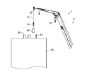
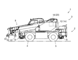
- the crane 1 is mainly composed of a vehicle 2 and a crane device 3.
- the vehicle 2 includes a pair of left and right front wheels 4 and a rear wheel 5.
- the vehicle 2 includes an outrigger 6 that is grounded and stabilized when carrying the cargo W.
- the vehicle 2 includes an engine, a transmission, and an actuator for driving them.
- the crane device 3 is freely turnable by a turning hydraulic motor 7 (see arrow A).
- the crane apparatus 3 includes a boom 8 so as to protrude forward from the rear part.
- the boom 8 can be raised and lowered by a boom raising and lowering hydraulic cylinder 9 (see arrow B).
- the boom 8 can be expanded and contracted by a telescopic hydraulic cylinder 10 (see arrow C).
- the boom 8 has a jib 15 at its tip.
- the jib 15 can be raised and lowered by a jib raising and lowering hydraulic cylinder 16 (see arrow E).
- the jib 15 is a part of the boom 8.
- a main wire rope 11 is stretched over the boom 8.
- a main winch 12 around which a main wire rope 11 is wound is disposed in the vicinity of the base end side of the boom 8, and a main hook 13 is suspended by the main wire rope 11 at the distal end portion of the boom 8.
- the main winch 12 is configured integrally with the hydraulic motor 14 and enables the main wire rope 11 to be wound and unwound. Therefore, the main hook 13 can be moved up and down by the hydraulic motor 14 (see arrow D).
- a sub-wire rope 17 is bridged over the boom 8 and the jib 15.
- a sub winch 18 around which a sub wire rope 17 is wound is disposed in the vicinity of the base end side of the boom 8, and a sub hook 19 is suspended from the jib 15 by a sub wire rope 17.
- the sub winch 18 is configured integrally with the hydraulic motor 20 and enables the sub wire rope 17 to be wound and unwound. Therefore, the subhook 19 can be raised and lowered by the hydraulic motor 20 (see arrow F).
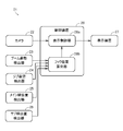
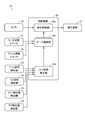
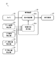
- the camera system 21 includes a camera 22, a boom posture detector 23, a jib posture detector 24, a main feed amount detector 25, a sub feed amount detector 26, a display device 27, and a control device 28.
- the camera 22 photographs the subject and its surroundings.
- the camera 22 is a so-called wide-angle camera, and is attached to the tip portion of the boom 8 (see FIG. 1).
- the number of cameras 22 may be plural.
- one camera is attached to each foot pin 33 (see FIG. 1) attached to both side surfaces of the tip portion of the boom 8.
- the foot pin 33 is used for attaching the jib 15 and protrudes left and right from the side surface of the boom 8.
- the boom posture detector 23 detects the posture of the boom 8.
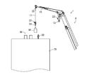
- the posture of the boom 8 is represented by a undulation angle G (see FIG. 1) with respect to the horizontal plane of the boom 8, and an extension length H (see FIG. 1) from the proximal end portion to the distal end portion of the boom 8.
- the jib posture detector 24 detects the posture of the jib 15.
- the posture of the jib 15 is represented by the undulation angle I (see FIG. 1) with respect to the horizontal plane of the jib 15.
- the jib 15 can be expanded and contracted, it is represented by an expansion / contraction length J (see FIG. 1) from the proximal end portion to the distal end portion of the jib 15 in addition to the undulation angle I (see FIG. 1).
- the main feed amount detector 25 detects the feed amount of the main wire rope 11.
- the feeding amount of the main wire rope 11 is the length of the main wire rope 11 fed from the main winch 12.
- the sub-feed amount detector 26 detects the feed amount of the sub-wire rope 17.
- the feeding amount of the sub wire rope 17 is the length of the sub wire rope 17 fed from the sub winch 18.
- the display device 27 displays an image taken by the camera 22. An image display mode will be described later.
- the control device 28 is connected to the camera 22 and the display device 27 to process information.
- the control device 28 includes a display control unit 28a and a hook position calculation unit 28b.
- the control device 28 stores various programs and data.
- the display control unit 28a cuts out a predetermined portion from the image taken by the camera 22 and enlarges or reduces it.
- the display control unit 28a is connected to the camera 22, the display device 27, and the hook position calculation unit 28b.
- the hook position calculation unit 28b calculates the positions of the main hook 13 and the sub hook 19 from the image captured by the camera 22.
- the hook position calculation unit 28b is connected to the boom posture detector 23, the jib posture detector 24, the main feed amount detector 25, the sub feed amount detector 26, and the display control unit 28a.
- the camera system 21 can cut out a portion including the subject from the image captured by the camera 22 and display it on the display device 27 in an enlarged or reduced manner. In this way, the camera system 21 can display almost the same image on the display device 27 without requiring pan-tilt operation by the operator. In addition, the camera system 21 can display a substantially similar image on the display device 27 without requiring the operator to perform a zoom operation. Note that such processing is electrically performed based on software, and thus is much faster than the conventional mechanical operation.
- the display mode of the image will be described with reference to FIGS.
- a description will be given assuming a situation where the luggage W is being transported to the roof of the building 29.
- the subject is described as the sub-hook 19, but it is obvious that the subject can be used as the main hook 13.
- the description will be made assuming that there is one camera, it is obvious that even if there are a plurality of cameras, it can be realized by photographing a subject with any one of the plurality of cameras and using an image obtained by photographing the subject. is there.
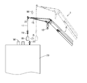
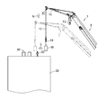
- the crane 1 moves the jib 15 up and down to carry the load W.
- a plurality of loads W have already been transported on the roof of the building 29, and an operator 30 stands near these loads W.
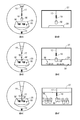
- 4A to 4C show images taken by the camera 22 in descending order of the undulation angle I of the jib 15.
- 4D shows an image obtained by cutting out and enlarging a portion including the sub hook 19 in FIG. 4A.
- FIG. 4E shows an enlarged image of a portion including the sub hook 19 in FIG. 4B.
- 4F shows an image obtained by cutting out and enlarging a portion including the sub hook 19 in FIG. 4C.
- the control device 28 can display an image taken by the camera 22 on the display device 27 (see FIGS. 4A to 4C). Note that the image taken by the camera 22 is distorted at the outer edge portion. Therefore, it is preferable to display a flat image without distortion by correcting the distortion. Further, by including the jib 15 in the image, the collision between the jib 15 and the building 29 may be monitored.
- control device 28 can cut out a portion including the sub hook 19 from the image taken by the camera 22 and display the enlarged portion on the display device 27 (see FIGS. 4D to 4F). For this reason, the operator can check the situation around the subhook 19 and the subhook 19. As a result, it is possible to confirm the load W suspended on the sub-hook 19 and the situation around the load W. In addition, since the operator can see the sub hook 19 or the luggage W from diagonally above, it is possible to check the height from the roof of the building 29 to the sub hook 19 or the luggage W.
- the crane 1 includes the camera 22, the display device 27 that displays an image captured by the camera 22, and the control device 28 that is connected to the camera 22 and the display device 27 and processes information. ing. Then, the control device 28 follows the subject (for example, the subhook 19) in the image captured by the camera 22, cuts out a portion including the subject (19), and displays it on the display device 27. According to this crane 1, since the location including the subject (19) is cut out and displayed, it is possible to check the situation around the subject (19) and the subject (19). Accordingly, it is possible to improve safety and work efficiency.
- the crane 1 includes a wire rope (main wire rope 11 and sub-wire rope 17) hanging from the boom 8 and a hook (main hook 13) that moves up and down as the wire rope (11 and 17) is retracted and extended.
- a sub-hook 19 When the subject is the hook (13, 19) or the luggage W suspended on the hook (13, 19) and the subject is the hook (13, 19), the hook (13, 19) in the image captured by the camera 22 is used. ), The location including the hook (13, 19) is displayed on the display device 27, and the subject is the luggage W, the location where the camera 22 follows the luggage W and includes the luggage W Is displayed on the display device 27.
- the control device 28 grasps the position of the luggage W by image recognition or the like.
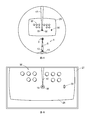
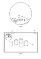
- a plurality of locations may be cut out from the image captured by the camera 22 and enlarged and displayed on the display device 27 (see FIG. 5). That is, in addition to the location including the subject (for example, the sub hook 19), the location including the worker 30 or the location including the obstacle may be cut out and enlarged and displayed on the display device 27. In order to realize such a display mode, it is necessary to grasp the presence of the worker 30 and the presence of an obstacle by image recognition or the like.
- the crane 1 when the crane 1 is remotely operated, it is preferable to display the operation direction of the remote operation and the movement direction of the operation target in agreement. That is, when the operation tool is operated to the right, it is preferable to display so that the main hook 13 or the sub hook 19 on the image is also moved to the right. Similarly, when the operation tool is operated to the left, it is preferable to display so that the main hook 13 or the sub hook 19 on the image is also moved to the left.
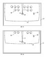
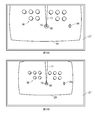
- FIG. 7A shows an image taken by the camera 22.
- FIG. 7B shows an enlarged image of a portion including the sub hook 19 in FIG. 7A.
- the control device 28 can cut out a portion including the sub hook 19 in the vertical direction of the tip portion of the jib 15 from the image taken by the camera 22 and display the enlarged portion on the display device 27. For this reason, the operator can check the situation around the subhook 19 and the subhook 19. As a result, it is possible to confirm the load W suspended on the sub-hook 19 and the situation around the load W.
- a portion including the boom 8 and the jib 15 may be cut out from the image captured by the camera 22 and displayed on the display device 27 (see FIG. 8). This is because by including the boom 8 and the jib 15 in the image, the collision between the boom 8 and the jib 15 and the building 29 can be monitored.
- the crane 1 according to the second embodiment will be described. Below, it demonstrates focusing on the part which is different with respect to the crane 1 which concerns on 1st embodiment.
- the jib 15 is assumed to be a part constituting the boom 8.
- the camera system 21 includes a mode switch 31 and a zoom adjustment switch 32. Further, the control device 28 has a zoom control unit 28c.
- the mode changeover switch 31 switches the operation mode of the camera 22.
- the zoom adjustment switch 32 is for adjusting the zoom magnification of the camera 22.
- the zoom control unit 28 c controls the zoom magnification of the camera 22.
- the display control unit 28a cuts out a predetermined portion from the image captured by the camera 22, and enlarges or reduces the cut-out image so that the image cut out with the adjusted or controlled zoom magnification is displayed on the display device 27. .
- the zoom control unit 28c is connected to the mode switch 31, the zoom adjustment switch 32, the display control unit 28a, and the hook position calculation unit 28b.
- the mode changeover switch 31 has selected “automatic mode” will be described with reference to FIG.
- the subject is described as the sub-hook 19, it is obvious that the subject can be used as the main hook 13.
- the description will be made assuming that there is one camera, it is obvious that even if there are a plurality of cameras, it can be realized by photographing a subject with any one of the plurality of cameras and using an image obtained by photographing the subject. is there.
- step S11 the control device 28 determines whether or not the mode switch 31 has selected the “automatic mode”. If it is determined that the mode is “automatic mode”, the process proceeds to step S12. If it is determined that the mode is not “automatic mode”, the process is kept waiting.
- step S12 the control device 28 grasps the change in the posture of the boom 8 and the change in the posture of the jib 15. That is, the control device 28 has the hoisting angle G (see FIG. 1) and the telescopic length H (see FIG. 1) of the boom 8, the hoisting angle I (see FIG. 1) and the telescopic length J (see FIG. 1) of the jib 15. To grasp the changes. At the same time, the control device 28 also grasps the change in the feed amount of the sub wire rope 17.
- step S ⁇ b> 13 the control device 28 determines whether or not the position of the camera 22 is lowered with respect to the sub hook 19 based on the change in the posture of the boom 8, the change in the posture of the jib 15, and the change in the feed amount of the sub wire rope 17. Judging. If it is determined that the position of the camera 22 has been lowered, the process proceeds to step S14. If it is determined that the position of the camera 22 is not lowered, the process proceeds to step S15. Note that when the position of the camera 22 is lowered, the distance from the camera 22 to the sub hook 19 is reduced (see arrow M in FIG. 11).
- step S14 the control device 28 lowers the zoom magnification of the camera 22 so that the size of the subhook 19 in the image does not change. This is because when the distance from the camera 22 to the sub hook 19 approaches, the sub hook 19 appears larger.
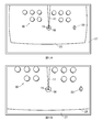
- FIG. 12A shows an image that is enlarged at a zoom magnification before the position including the sub hook 19 is cut out from the image before the position of the camera 22 is lowered and is lowered.
- FIG. 12B shows an image enlarged at a zoom magnification after the portion including the sub hook 19 is cut out from the image after the position of the camera 22 is lowered and lowered.
- step S15 the control device 28 determines whether or not the position of the camera 22 is raised with respect to the sub hook 19 based on the change in the posture of the boom 8, the change in the posture of the jib 15, and the change in the feed amount of the sub wire rope 17. Judging. If it is determined that the position of the camera 22 has been raised, the process proceeds to step S16. If it is determined that the position of the camera 22 is not raised, the control mode is terminated. When the position of the camera 22 is increased, the distance from the camera 22 to the sub hook 19 is increased (see arrow N in FIG. 13).
- step S16 the control device 28 increases the zoom magnification of the camera 22 so that the size of the subhook 19 in the image does not change. This is because if the distance from the camera 22 to the sub-hook 19 is increased, the sub-hook 19 appears smaller.
- FIG. 14A shows an image that is enlarged at a zoom magnification before the position including the sub hook 19 is cut out from the image before the position of the camera 22 is raised and is increased.
- FIG. 14B shows an image that is enlarged at a zoom magnification after the portion including the sub hook 19 is cut out from the image after the position of the camera 22 is raised and is increased.
- step S21 the control device 28 determines whether or not the mode changeover switch 31 has selected the “manual mode”. If it is determined that the mode is the “manual mode”, the process proceeds to step S22. If it is determined that the mode is not the “manual mode”, it is kept waiting.
- step S22 the control device 28 determines whether or not the zoom adjustment switch 32 has been operated to one side (in the direction of decreasing the zoom magnification). If it is determined that the zoom adjustment switch 32 has been operated to one side, the process proceeds to step S23. If it is determined that the zoom adjustment switch 32 has not been operated to one side, the process proceeds to step S24.
- step S23 the control device 28 lowers the zoom magnification of the camera 22 so that the sub hook 19 in the image becomes smaller.
- FIG. 16A shows an image that has been cut out from the image before the zoom magnification is lowered, including the sub-hook 19 and enlarged at the zoom magnification before the zoom magnification is lowered.
- FIG. 16B shows an image enlarged at the zoom magnification after cutting out the portion including the sub hook 19 from the image after reducing the zoom magnification.
- step S24 the control device 28 determines whether or not the zoom adjustment switch 32 has been operated to the other side (direction to increase the zoom magnification). If it is determined that the zoom adjustment switch 32 has been operated to the other side, the process proceeds to step S25. When it is determined that the zoom adjustment switch 32 has not been operated to the other side, this control mode is terminated.
- step S25 the control device 28 increases the zoom magnification of the camera 22 so that the sub hook 19 in the image becomes large.
- FIG. 17A shows an image that is cut out from the image before the zoom magnification is increased, including the sub hook 19 and enlarged at the zoom magnification before the zoom magnification is increased.
- FIG. 17B shows an image enlarged by zooming after the portion including the sub hook 19 is cut out from the image after increasing the zoom magnification.
- the crane 1 changes the zoom magnification of the camera 22, changes the size of the subject (for example, the sub hook 19), and displays it on the display device 27.
- the size of the subject (19) can be changed to a size that can be easily seen by the operator and displayed on the display device 27, so that the situation around the subject (19) and the subject (19) can be easily understood.
- the crane 1 further includes a camera 22, a display device 27 that displays an image captured by the camera 22, and a control device 28 that is connected to the camera 22 and the display device 27 and processes information. . Then, the control device 28 reduces the zoom magnification of the camera 22 when the distance from the camera 22 to the subject (for example, the sub hook 19) approaches, and zooms the camera 22 when the distance from the camera 22 to the subject (19) increases. The magnification is increased and displayed on the display device 27. According to the crane 1, since the size of the subject (19) in the image does not change much, the situation around the subject (19) and the subject (19) can be easily understood. Accordingly, it is possible to improve safety and work efficiency.
- the crane 1 includes a wire rope (main wire rope 11 and sub-wire rope 17) hanging from the boom 8 and a hook (main hook 13) that moves up and down as the wire rope (11 and 17) is retracted and extended.
- a sub-hook 19 Then, regardless of the distance from the camera 22 to the hook (13, 19), the size of the hook (13, 19) is displayed on the display device 27 so as to be constant. Or it displays on the display device 27 so that the size of the package W is constant regardless of the distance from the camera 22 to the package W.
- the control device 28 grasps the position of the luggage W by image recognition or the like.
- the crane 1 is provided with a mode switch 31.
- the mode switch 31 can select at least “automatic mode” and “manual mode”. By doing so, the operator can arbitrarily change the display mode of the image.
- the crane 1 includes a zoom adjustment switch 32.
- the zoom adjustment switch 32 can adjust the zoom magnification when the mode change-over switch 31 selects “manual mode”. By doing so, the operator can arbitrarily change the size of the subject (for example, the sub hook 19) in the image.
- the crane 1 according to the third embodiment will be described. Below, it demonstrates focusing on the part which is different with respect to the crane 1 which concerns on 1st embodiment.
- the jib 15 is assumed to be a part constituting the boom 8.
- the camera 22 is attached to the tip of the jib 15.
- the camera system 21 includes a second camera 22 and a third camera 22.
- the control device 28 has a moving direction calculation unit 28d.
- the second camera 22 is attached to the hook block of the main hook 13.
- the third camera 22 is attached to the hook block of the sub hook 19.
- the moving direction calculation unit 28d calculates the moving direction of the main hook 13 and the sub hook 19 (see arrows P in FIGS. 20A and 20B, FIGS. 21A and 21B).
- the movement direction calculation unit 28d is connected to the boom posture detector 23, the jib posture detector 24, the main feed amount detector 25, the sub feed amount detector 26, and the display control unit 28a.
- an image display mode will be described with reference to FIGS.
- the description will be made on the assumption that the luggage W is being transported to the roof of the building 29.
- the subject is described as the sub-hook 19, but it is obvious that the subject can be used as the main hook 13.
- the first camera 22, the second camera 22, and the third camera 22 are each described as one, but even if each camera is a plurality of cameras, the subject is photographed by any one of the plurality of cameras.
- the image can be obtained by using an image in which the subject is photographed.
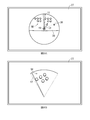
- FIG. 20A shows an image cut out in a circle around the subhook 19 from the image taken by the first camera 22.
- FIG. 20B shows an image obtained by cutting out and enlarging a partial region including the moving direction of the sub-hook 19 in FIG. 20A.
- the control device 28 can cut out a partial region including the moving direction of the sub hook 19 from the image captured by the first camera 22 and display the partial region on the display device 27 in an enlarged manner. For this reason, the operator can confirm the state of the moving direction of the sub hook 19 from the image of the boom viewpoint (the viewpoint looking down from the boom 8).
- FIG. 21A shows an image taken by the third camera 22.
- FIG. 21B shows an image obtained by cutting out and enlarging a partial region including the moving direction of the sub hook 19 in FIG. 21A.
- the control device 28 can cut out a partial region including the moving direction of the sub hook 19 from the image captured by the third camera 22 and display the partial region on the display device 27 in an enlarged manner. For this reason, the operator can confirm the state of the movement direction of the sub hook 19 from the image of the hook viewpoint (the viewpoint viewed from the sub hook 19). In addition, you may display together the image cut out circularly centering on the subhook 19 from the image image
- the crane 1 includes the camera 22, the display device 27 that displays an image captured by the camera 22, and the control device 28 that is connected to the camera 22 and the display device 27 and processes information. ing.
- the control apparatus 28 grasps
- the crane 1 has a camera 22 attached to the boom 8 or hook (main hook 13 / subhook 19), and a part including the moving direction of the hook (13/19) from the image taken by the camera 22.
- the area is cut out and displayed on the display device 27.
- the state of the movement direction of the hooks (13, 19) can be confirmed from the image of the boom viewpoint (viewpoint looking down from the boom 8) or the hook viewpoint (viewpoint viewed from the main hook 13 or the sub hook 19).
- the camera 22 when the camera 22 is attached to the tip portion of the boom 8, the camera 22 can be used for photographing road conditions when the crane 1 is in the traveling posture (see FIG. 22). For this reason, the operator can confirm safety by looking at the image taken by the camera 22. If one camera is attached to each foot pin 33, a wider range of road conditions can be photographed. At this time, the operator can confirm the safety by looking at an image of a wider range of road conditions.
- the present invention can be used for a crane. Specifically, it can be used for cranes that have improved safety and improved work efficiency.
Landscapes
- Engineering & Computer Science (AREA)
- Mechanical Engineering (AREA)
- Control And Safety Of Cranes (AREA)
Abstract
L'invention vise à fournir une grue offrant une sécurité améliorée et une efficacité de travail améliorée. L'invention concerne une grue (1) comprenant une flèche (8), ladite grue comprenant une caméra (22), un dispositif d'affichage (27) destiné à afficher une image photographiée par la caméra (22) et un dispositif de commande (28) relié à la caméra (22) et au dispositif d'affichage (27), ledit dispositif de commande (28) étant destiné à exécuter un processus d'information. Le dispositif de commande (28) : suit un sujet photographique (par exemple, un sous-crochet (19)) dans l'image photographiée par la caméra (22) ; rogne une partie comportant le sujet photographique (le sous-crochet (19)) ; et affiche ladite partie rognée sur le dispositif d'affichage (27).
Applications Claiming Priority (2)
| Application Number | Priority Date | Filing Date | Title |
|---|---|---|---|
| JP2018-043253 | 2018-03-09 | ||
| JP2018043253A JP2019156533A (ja) | 2018-03-09 | 2018-03-09 | クレーン |
Publications (1)
| Publication Number | Publication Date |
|---|---|
| WO2019172413A1 true WO2019172413A1 (fr) | 2019-09-12 |
Family
ID=67847108
Family Applications (1)
| Application Number | Title | Priority Date | Filing Date |
|---|---|---|---|
| PCT/JP2019/009292 Ceased WO2019172413A1 (fr) | 2018-03-09 | 2019-03-08 | Grue |
Country Status (2)
| Country | Link |
|---|---|
| JP (1) | JP2019156533A (fr) |
| WO (1) | WO2019172413A1 (fr) |
Families Citing this family (4)
| Publication number | Priority date | Publication date | Assignee | Title |
|---|---|---|---|---|
| JP7501098B2 (ja) * | 2020-05-21 | 2024-06-18 | 株式会社タダノ | ブームカメラシステムおよびブームカメラシステムを備える移動式クレーン |
| JP7639431B2 (ja) | 2021-03-19 | 2025-03-05 | コベルコ建機株式会社 | 遠隔操作支援サーバおよび遠隔操作支援システム |
| JP2023152333A (ja) | 2022-04-04 | 2023-10-17 | 日鉄テックスエンジ株式会社 | 天井クレーン監視システム |
| EP4703314A1 (fr) | 2023-04-28 | 2026-03-04 | Gogoh Co. Ltd. | Système de pont roulant |
Citations (8)
| Publication number | Priority date | Publication date | Assignee | Title |
|---|---|---|---|---|
| JPH07309577A (ja) * | 1994-05-17 | 1995-11-28 | Ohbayashi Corp | クレーン用テレビモニタ装置 |
| JPH0853290A (ja) * | 1994-08-10 | 1996-02-27 | Tadano Ltd | クレーンの吊荷監視装置 |
| JP2001002369A (ja) * | 1999-06-25 | 2001-01-09 | Kobelco Contstruction Machinery Ltd | クレーンの吊荷監視装置 |
| JP2013142037A (ja) * | 2012-01-12 | 2013-07-22 | Tadano Ltd | 作業車用の吊荷監視カメラ装置 |
| JP2013159480A (ja) * | 2012-02-08 | 2013-08-19 | Sumitomo Heavy Ind Ltd | 視覚補助装置 |
| JP2013193825A (ja) * | 2012-03-19 | 2013-09-30 | Tadano Ltd | クレーン作業監視装置 |
| CN103359642A (zh) * | 2013-07-29 | 2013-10-23 | 中联重科股份有限公司 | 一种塔机作业监控系统、方法和塔机 |
| WO2017141320A1 (fr) * | 2016-02-15 | 2017-08-24 | 株式会社大島造船所 | Dispositif de détermination, système de détermination, programme, et support d'enregistrement pour prendre en charge le fonctionnement de grue |
-
2018
- 2018-03-09 JP JP2018043253A patent/JP2019156533A/ja active Pending
-
2019
- 2019-03-08 WO PCT/JP2019/009292 patent/WO2019172413A1/fr not_active Ceased
Patent Citations (8)
| Publication number | Priority date | Publication date | Assignee | Title |
|---|---|---|---|---|
| JPH07309577A (ja) * | 1994-05-17 | 1995-11-28 | Ohbayashi Corp | クレーン用テレビモニタ装置 |
| JPH0853290A (ja) * | 1994-08-10 | 1996-02-27 | Tadano Ltd | クレーンの吊荷監視装置 |
| JP2001002369A (ja) * | 1999-06-25 | 2001-01-09 | Kobelco Contstruction Machinery Ltd | クレーンの吊荷監視装置 |
| JP2013142037A (ja) * | 2012-01-12 | 2013-07-22 | Tadano Ltd | 作業車用の吊荷監視カメラ装置 |
| JP2013159480A (ja) * | 2012-02-08 | 2013-08-19 | Sumitomo Heavy Ind Ltd | 視覚補助装置 |
| JP2013193825A (ja) * | 2012-03-19 | 2013-09-30 | Tadano Ltd | クレーン作業監視装置 |
| CN103359642A (zh) * | 2013-07-29 | 2013-10-23 | 中联重科股份有限公司 | 一种塔机作业监控系统、方法和塔机 |
| WO2017141320A1 (fr) * | 2016-02-15 | 2017-08-24 | 株式会社大島造船所 | Dispositif de détermination, système de détermination, programme, et support d'enregistrement pour prendre en charge le fonctionnement de grue |
Also Published As
| Publication number | Publication date |
|---|---|
| JP2019156533A (ja) | 2019-09-19 |
Similar Documents
| Publication | Publication Date | Title |
|---|---|---|
| WO2019172413A1 (fr) | Grue | |
| JP5876679B2 (ja) | 性能線表示装置 | |
| JP5462008B2 (ja) | 画像表示システム | |
| JP7106929B2 (ja) | 作業車両 | |
| JP2013142037A (ja) | 作業車用の吊荷監視カメラ装置 | |
| JP6589468B2 (ja) | 移動式クレーンの周囲表示装置 | |
| JP7114950B2 (ja) | 遠隔操作端末及び作業車両 | |
| EP3831766B1 (fr) | Grue | |
| JP3402771B2 (ja) | クレーンの吊荷監視装置 | |
| JP2018042205A (ja) | 画像表示システム | |
| WO2019163875A1 (fr) | Dispositif de caméra, système de surveillance de charge suspendue et machine de travail | |
| JP2019142679A (ja) | 吊荷監視装置 | |
| JP3226637U (ja) | 遠隔作業支援システム | |
| JP7006442B2 (ja) | クレーン | |
| CN111819147B (zh) | 作业车辆 | |
| US20100193458A1 (en) | Controller for an Adjustable Jib Extension of a Mobile Crane | |
| JP2018087059A (ja) | 作業車両 | |
| JP6772765B2 (ja) | 画像表示装置 | |
| US12187584B2 (en) | Image system and work vehicle provided with image system | |
| JP7668658B2 (ja) | クレーンの監視装置及びクレーン | |
| JPWO2019163875A1 (ja) | カメラ装置、吊荷監視システム、及び、作業機 | |
| JP2018095362A (ja) | クレーン | |
| WO2024262357A1 (fr) | Dispositif de grue | |
| JP2019151467A (ja) | フック位置制御装置 | |
| WO2024262519A1 (fr) | Dispositif de grue |
Legal Events
| Date | Code | Title | Description |
|---|---|---|---|
| 121 | Ep: the epo has been informed by wipo that ep was designated in this application |
Ref document number: 19763922 Country of ref document: EP Kind code of ref document: A1 |
|
| NENP | Non-entry into the national phase |
Ref country code: DE |
|
| 122 | Ep: pct application non-entry in european phase |
Ref document number: 19763922 Country of ref document: EP Kind code of ref document: A1 |