WO2019172444A1 - Ruban de fibre optique et câble à fibres optiques - Google Patents
Ruban de fibre optique et câble à fibres optiques Download PDFInfo
- Publication number
- WO2019172444A1 WO2019172444A1 PCT/JP2019/009482 JP2019009482W WO2019172444A1 WO 2019172444 A1 WO2019172444 A1 WO 2019172444A1 JP 2019009482 W JP2019009482 W JP 2019009482W WO 2019172444 A1 WO2019172444 A1 WO 2019172444A1
- Authority
- WO
- WIPO (PCT)
- Prior art keywords
- optical fiber
- intermittent connection
- core wire
- colored
- fiber ribbon
- Prior art date
- Legal status (The legal status is an assumption and is not a legal conclusion. Google has not performed a legal analysis and makes no representation as to the accuracy of the status listed.)
- Ceased
Links
Images




Classifications
-
- G—PHYSICS
- G02—OPTICS
- G02B—OPTICAL ELEMENTS, SYSTEMS OR APPARATUS
- G02B6/00—Light guides; Structural details of arrangements comprising light guides and other optical elements, e.g. couplings
- G02B6/44—Mechanical structures for providing tensile strength and external protection for fibres, e.g. optical transmission cables
- G02B6/4479—Manufacturing methods of optical cables
- G02B6/4482—Code or colour marking
-
- G—PHYSICS
- G02—OPTICS
- G02B—OPTICAL ELEMENTS, SYSTEMS OR APPARATUS
- G02B6/00—Light guides; Structural details of arrangements comprising light guides and other optical elements, e.g. couplings
- G02B6/44—Mechanical structures for providing tensile strength and external protection for fibres, e.g. optical transmission cables
- G02B6/4401—Optical cables
- G02B6/4403—Optical cables with ribbon structure
-
- G—PHYSICS
- G02—OPTICS
- G02B—OPTICAL ELEMENTS, SYSTEMS OR APPARATUS
- G02B6/00—Light guides; Structural details of arrangements comprising light guides and other optical elements, e.g. couplings
- G02B6/44—Mechanical structures for providing tensile strength and external protection for fibres, e.g. optical transmission cables
- G02B6/4401—Optical cables
- G02B6/4405—Optical cables with longitudinally spaced waveguide clamping
-
- G—PHYSICS
- G02—OPTICS
- G02B—OPTICAL ELEMENTS, SYSTEMS OR APPARATUS
- G02B6/00—Light guides; Structural details of arrangements comprising light guides and other optical elements, e.g. couplings
- G02B6/44—Mechanical structures for providing tensile strength and external protection for fibres, e.g. optical transmission cables
- G02B6/4401—Optical cables
- G02B6/4429—Means specially adapted for strengthening or protecting the cables
- G02B6/443—Protective covering
-
- G—PHYSICS
- G02—OPTICS
- G02B—OPTICAL ELEMENTS, SYSTEMS OR APPARATUS
- G02B6/00—Light guides; Structural details of arrangements comprising light guides and other optical elements, e.g. couplings
- G02B6/44—Mechanical structures for providing tensile strength and external protection for fibres, e.g. optical transmission cables
- G02B6/4479—Manufacturing methods of optical cables
- G02B6/448—Ribbon cables
Definitions
- the present invention relates to an optical fiber ribbon and an optical fiber cable. More specifically, the optical fiber ribbon and the optical fiber ribbon are formed by intermittently adhering and connecting adjacent optical fiber colored cores to each other in the longitudinal direction and the tape width direction by an intermittent connection portion. Relates to optical fiber cables.
- optical fiber cables are also required to have a smaller diameter and higher density.
- optical fiber ribbons have been proposed in order to realize a reduction in the diameter and density of the optical fiber cable.
- the adjacent optical fibers are intermittently connected in the longitudinal direction to obtain a tape width.
- optical fiber ribbon that is alternately arranged so that connecting portions adjacent in the direction do not overlap (see, for example, Patent Document 1).
- the optical fiber tape core wire is made of an ultraviolet curable resin or the like, in which a plurality of optical fiber core wires (optical fiber colored core wires) obtained by applying a protective coating to the optical fiber with an ultraviolet curable resin or the like are arranged in a planar shape. It is connected and integrated at the connecting portion.
- Japanese Patent No. 5117519 JP 2001-264604 A Japanese Patent No. 5149230 Japanese Patent No. 6169060
- an operation of applying a resin between the optical fiber colored core wires and the optical fiber colored core wires Must be synchronized. Therefore, in order to manufacture an optical fiber ribbon with a high linear velocity (for example, a linear velocity of 200 m / min or more as the linear velocity of an optical fiber colored core), the viscosity at the time of applying a resin, The ease of resin wear is greatly affected.
- the present invention has been made in view of the above-described problems, and is an intermittently connected optical fiber tape core formed by adhering and connecting adjacent optical fiber colored cores with an intermittently connected portion at a high speed.
- An object of the present invention is to provide an optical fiber ribbon and an optical fiber cable that can be manufactured.
- an optical fiber ribbon according to the present invention has at least two coating layers covering the optical fiber formed around the optical fiber, and the outermost layer of the coating layers is colored.
- the optical fiber colored cores configured in parallel are arranged in parallel, and the adjacent optical fiber colored cores are optical fiber tape cores connected in the length direction by intermittent connection parts, and the intermittent connection parts
- it is characterized by containing a polyol having a weight average molecular weight of 2500 to 4000 and containing cellulose nanofibers in an amount of 0.01 to 10.0% by mass with respect to the whole intermittently connected portion.
- the optical fiber ribbon according to the present invention is characterized in that, in the above-described present invention, the intermittent connection portion contains 4 to 30% by mass of the polyol with respect to the entire intermittent connection portion.
- the optical fiber ribbon according to the present invention is characterized in that, in the above-described present invention, the cellulose nanofiber is contained in an amount of 0.1 to 5.0% by mass with respect to the entire intermittent connection portion.
- the material forming the intermittent connection portion has a viscosity at a shear rate of 10 1 1 / s obtained from dynamic viscoelasticity at 25 ° C. of 2. 0 to 8.2 Pa ⁇ s.
- the optical fiber ribbon according to the present invention is the optical fiber tape according to the present invention, wherein the cellulose nanofiber is selected from the group consisting of a chemical defibrating method, a mechanical defibrating method, and a water collision defibrating method. It is characterized by being defibrated by.
- the optical fiber ribbon according to the present invention is characterized in that, in the above-described present invention, the cellulose nanofiber is made from kraft pulp as a fiber raw material.
- the optical fiber ribbon according to the present invention is characterized in that an adhesive strength between the optical fiber colored core and the intermittent connection portion is 0.1 N or more.
- An optical fiber cable according to the present invention includes the above-described optical fiber tape core wire of the present invention.
- the optical fiber tape core of the present invention is not limited to cellulose nanofibers. It is set as the structure contained in the range. With this configuration, scattering of the material can be suppressed by centrifugal force generated with rotation of an application roll or the like that applies the material during manufacturing, and the amount of application to the optical fiber colored core can be stabilized. And it becomes an optical fiber cable provided with the optical fiber tape core wire and the said optical fiber colored core wire which can maintain suppression of this scattering etc. also at high-speed manufacture.
- the optical fiber ribbon 2 according to the present invention, at least two coating layers that cover the optical fiber 10 are formed around the optical fiber 10, and the outermost layer of the coating layers is colored.
- the colored core wires 1 are arranged in parallel, and the adjacent optical fiber colored core wires 1 are intermittently connected in the length direction by the intermittent connecting portion 3.
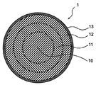
- FIG. 1 is a cross-sectional view showing an example of the structure of the optical fiber colored core wire 1.
- FIG. 2 is a cross-sectional view showing another example of the structure of the optical fiber colored core wire 1.
- 1 and 2 1 is an optical fiber colored core wire, 10 is an optical fiber, 11 is a primary coating layer, 12 is a secondary coating layer, 12a is a colored secondary coating layer (FIG. 2 only), 13 is Colored layers (FIG. 1 only) are shown respectively.
- a primary coating layer 11 (primary layer) around an optical fiber 10 such as a glass optical fiber
- a secondary coating layer 12 (secondary layer) around the primary coating layer 11, and a secondary coating layer.
- a colored layer 13 colored around 12 is formed in this order, and constitutes the optical fiber colored core wire 1.
- the colored layer 13 is the outermost layer of the optical fiber colored core wire 1.
- a primary coating layer 11 and a secondary coating layer 12a colored around the primary coating layer 11 are formed around the optical fiber 10 in this order.
- the colored secondary coating layer 12 a is the outermost layer of the optical fiber colored core wire 1.
- the colored layer 13 that is the outermost layer of the optical fiber colored core wire 1 and the colored secondary coating layer 12a may be combined to form the colored layer 13 or the like.
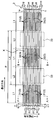
- FIG. 3 is a front view showing an aspect of the optical fiber ribbon 2.
- 4 and 5 are diagrams showing the connection state of the optical fiber ribbon 2 (FIG. 4 is a cross-sectional view taken along the line AA in FIG. 3 including the intermittent connection portion 31, and FIG. Is a cross-sectional view taken along the line BB of FIG. 3 to 5 show an optical fiber ribbon 2 composed of 12 optical fiber colored cores 1 for convenience.
- the intermittently connected optical fiber tape core 2 is an optical fiber colored core wire 1 arranged in parallel. It is also called intermittent connection in the length direction.
- the connecting portion intermittent connecting portion 3
- the optical fiber colored core wires 1 can be connected and integrated.
- a pair of optical fiber colored cores t1 composed of the optical fiber colored core 1a and the optical fiber colored core 1b is lengthened by the intermittent connecting portion 31. (See FIG. 3).
- adjacent intermittent connection portions 31 can be provided at equal intervals, and the lengths of the intermittent connection portions 31 can also be made equal.
- optical fiber colored core wire pair t3 consisting of optical fiber colored core wire 1c and optical fiber colored core wire 1d
- optical fiber colored core wire pair t5 consisting of optical fiber colored core wire 1e and optical fiber colored core wire 1f
- An optical fiber colored core pair t7 composed of an optical fiber colored core 1g and an optical fiber colored core 1h
- an optical fiber colored core t9 composed of an optical fiber colored core 1i and an optical fiber colored core 1j
- an optical fiber colored core is the same applies to the optical fiber colored core pair t11 including the line 1k and the optical fiber colored core 1l.
- intermittent coupling portions 31 are provided so that the arrangement in the tape width direction is the same (see FIG. 3). ). Therefore, the non-connected portion (single-core portion where the intermittently connected portion 3 is not formed) of the six pairs of optical fiber colored core wires t1, t3, t5, t7, t9, and t11 is shown in FIG.
- the portion surrounded by the dotted line.) 33 is also a common position when viewed from the tape width direction.
- the optical fiber colored core wire pair t2 composed of the optical fiber colored core wire 1b and the optical fiber colored core wire 1c is intermittently connected in the length direction by the intermittent connecting portion 32.
- the adjacent intermittent connection parts 32 can be provided at equal intervals, and the lengths of the intermittent connection parts 32 can also be made equal.
- optical fiber colored core wire pair t6 consisting of optical fiber colored core wire 1d and optical fiber colored core wire 1e
- optical fiber colored core wire pair t6 consisting of optical fiber colored core wire 1f and optical fiber colored core wire 1g
- optical fiber colored core wire t8 composed of the optical fiber colored core wire 1h and the optical fiber colored core wire 1i
- optical fiber colored core wire pair t10 composed of the optical fiber colored core wire 1j and the optical fiber colored core wire 1k.
- intermittent coupling portions 32 are provided so that the arrangement in the tape width direction is the same. Therefore, the unconnected portions 33 of the five pairs of optical fiber colored cores t2, t4, t6, t8, and t10 are also in a common position when viewed from the tape width direction.
- the intermittently connected optical fiber ribbon 2 is not separated from the intermittently connected portions 31 and 32 in the length direction and the tape width direction with respect to the adjacent two (two) optical fiber colored cores 1.
- the connecting portions 33 are formed so as to be alternately arranged with a predetermined length, and the adjacent optical fiber colored core wires 1 are intermittently connected in the length direction by the intermittent connecting portion 3 (for example, FIG. 3).
- An optical fiber colored core wire t1 composed of the optical fiber colored core wire 1a and the optical fiber colored core wire 1b, an optical fiber colored core wire pair t2 composed of the optical fiber colored core wire 1b and the optical fiber colored core wire 1c, etc. reference.).
- intermittent pairs of optical fiber colored core pairs t1 to t11 composed of two adjacent cores (two) formed with intermittent coupling portions 31 and 32 are formed. Both sides (outside) in the tape width direction of the portion where the connecting portion 3 is formed are not connected (for example, from the optical fiber colored core 1c and the optical fiber colored core 1d shown in FIG. 4).
- the optical fiber colored core pair t3 is formed with an intermittent coupling portion 31 that couples the two optical fiber colored core wires 1c and 1d, while a portion in which the intermittent coupling portion 3 is formed in the tape width direction. Both sides (outside) are not connected.
- the length L1 of the intermittent connection portions 31 and 32 in the optical fiber ribbon 2 is preferably about 5 to 35 mm, and the length of the non-connection portion 33 is The length L2 is preferably about 5 to 15 mm.
- the pitch P in the optical fiber ribbon 2 indicates the length of the intermittent connection part 31 to the intermittent connection part 31 (or the intermittent connection part 32 to the intermittent connection part 32) adjacent in the length direction.
- the portion 31 to the intermittently connected portion 31) is preferably 100 mm or less, and generally preferably 20 to 90 mm, but is not particularly limited to this range.
- the non-connecting portion refers to a single core portion (single core portion) where the intermittent connecting portion 3 is not formed.
- X shown in FIG. 3 is also a non-connecting portion (non-connecting portion X having a length LX).
- LX of the pair of optical fiber colored core wires is LX.
- the thickness is preferably 15 to 55 mm, but is not particularly limited to this range.
- the intermittently connecting portion 3 shown in FIG. 3 and the like can be formed by curing the following components, for example.
- the component constituting the intermittent connection portion 3 includes a polyol having a weight average molecular weight (M w ) of 2500 to 4000.
- the polyol having such a weight average molecular weight (hereinafter sometimes simply referred to as “molecular weight”) can exist without reacting with the network of the ultraviolet curable resin constituting the intermittent connection portion 3.
- the intermittent connection part 3 is that the polyol is swollen in the dense network structure of the ultraviolet curable resin, and plays a role of a plasticizer for the ultraviolet curable resin.
- the Young's modulus of the intermittent connection part 3 moderate, flexibility and elongation can be provided to the intermittent connection part 3 also under low temperature conditions. Further, the polyol can bleed on the surface of the intermittent connection portion 3 to suppress friction between the optical fiber units 21.
- the weight average molecular weight of the polyol is in the above-described range, it is considered that the molecular weight of the colored layer 13 of the optical fiber colored core wire 1 is larger, so that the colored layer 13 does not pass through the mesh and does not move.
- the molecular weight of the polyol is as large as 2500 to 4000, it is possible to control the Young's modulus of the intermittent connection portion 3 by increasing the polyol content. As described above, the presence of the polyol in the intermittent connection portion 3 can impart flexibility and elongation to the intermittent connection portion 3 even under a low temperature condition, and the polyol bleeds on the surface of the intermittent connection portion 3. The friction between the optical fiber units 21 can be suppressed.
- polyol examples include polypropylene glycol, polyethylene glycol, and polytetramethylene glycol.
- those having no branched structure such as polyethylene glycol and polytetramethylene glycol are crystallized at low temperatures. There is a case where bending due to crystals occurs at the interface between the colored layer 13 and the intermittent coupling portion 3 and causes an increase in loss.
- polypropylene glycol having a branched structure does not crystallize even at a low temperature of ⁇ 60 ° C., and the above-described effects of the polyol can be reliably obtained. Therefore, it is preferable to use polypropylene glycol as the polyol.
- Polypropylene glycol is produced by addition polymerization of polypropylene oxide (PO) to polyfunctional alcohol using an alkali catalyst, but ethylene oxide (EO) may be added and used to enhance the reaction, but ethylene oxide is added. Then, since hydrophilicity becomes high, it is preferable to use only polypropylene oxide (PO) as an additional substance.
- PO polypropylene oxide
- EO ethylene oxide
- the weight average molecular weight of the polyol contained in the intermittent connection part 3 is 2500 to 4000.
- the weight average molecular weight of the polyol is smaller than 2500, the polyol may migrate through the colored layer 13 in contact with the intermittent connection portion 3.
- it when it is set as the optical fiber cable 4, it may transfer to the buffer layer and coating layer (sheath) of the optical fiber cable which touches the intermittent connection part 3. Due to such a migration of polyol, the above-described effects may not be achieved.
- the viscosity increases when mixed with the ultraviolet curable resin, so that the coating amount when applying the intermittent connection part 3 at the time of manufacture is lowered, resulting in poor adhesion.
- the viscosity can be lowered by increasing the heating temperature or the like.
- the heating temperature is increased, the amount of resin at the time of application tends to increase, and the thickness of the intermittent connection portion 3 increases. It may be a factor.
- stringing may occur between the intermittently connected portion and the roll portion, which may be a factor that contaminates the surroundings.
- the content of the polyol contained in the intermittent connection part 3 is preferably 4 to 30% by mass with respect to the entire intermittent connection part 3 (the whole components constituting the intermittent connection part 3).
- the content of polyol relative to the entire intermittent connection portion 3 is less than 4% by mass, the flexibility and elongation when unitized are insufficient, and the risk of cracking of the intermittent connection portion 3 is increased when ironing is applied. There is.
- the content exceeds 30% by mass, the viscosity decreases, which may cause application failure or cause scattering from the roll.
- the polyol content is preferably 4 to 30% by mass with respect to the entire intermittently connected portion 3.
- UV curable resin that coats the optical fiber and components generally used as an additive component thereof can be used.
- oligomers, dilutions, and the like can be used.
- Monomers, photoinitiators, silane coupling agents, sensitizers, pigments, fillers, and other various additives can be used.
- the oligomer for example, polyether urethane acrylate, epoxy acrylate, polyester acrylate, silicone acrylate and the like can be used. These may be used alone or in combination of two or more.
- the Young's modulus and the glass transition temperature (Tg) of the intermittently connected portion 3 as a whole can be adjusted by the skeleton structure and molecular weight of the oligomer, and the type and added amount of the diluted monomer described later. As will be described later, the Young's modulus can be adjusted by reducing the molecular weight of the oligomer or increasing the functional group of the monomer.
- polyether-type urethane acrylate as an oligomer
- a polyol such as polypropylene glycol, polyethylene glycol, or polytetramethylene glycol
- a polypropylene glycol having a branched structure can be used.
- Hydroxy compound having an unsaturated double bond that is reactive to ultraviolet rays via an aromatic diisocyanate at the hydroxyl groups at both ends as a skeletal component preferably using such polypropylene glycol as an intermediate block It is preferable to use an oligomer in which is bound.
- polypropylene glycol as a polyol and using an oligomer having polypropylene glycol as an intermediate block as an oligomer, crystallization at a low temperature of ⁇ 60 ° C. does not cause crystallization, so that crystallization at a low temperature can be efficiently prevented.
- the oligomer to be used those having a weight average molecular weight of 500 to 2000 are preferred, and those having a weight average molecular weight of 1000 to 2000 are particularly preferred.
- aromatic diisocyanates such as tolylene diisocyanate (TDI) and isophorone diisocyanate (IPDI) can be used.
- TDI tolylene diisocyanate
- IPDI isophorone diisocyanate
- a hydroxy type compound such as hydroxyethyl acrylate (HEA) etc. can be used, for example.
- a dilution monomer can be blended mainly for viscosity adjustment within a range that does not interfere with the purpose and effect of addition of cellulose nanofiber described later.
- a dilution monomer a monofunctional monomer, a bifunctional monomer, a polyfunctional monomer, etc. can be used, for example.
- dilutable monomers for example, PO-modified nonylphenol acrylate, isobornyl acrylate, 2-ethylhexyl acrylate, isononyl acrylate, isodecyl acrylate, polyethylene glycol acrylate, N-vinyl pyrrolidone, N-vinyl Examples include caprolactam and lauryl acrylate.
- Bifunctional and polyfunctional monomers include 1,6-hexanediol diacrylate, bisphenol A epoxy acrylate, tripropylene glycol diacrylate, tricyclodecane dimethylol diacrylate, EO-modified bisphenol A diacrylate, and hexanediol diacrylate.
- An acrylate etc. are mentioned. One of these may be used alone, or two or more thereof may be used in combination. Note that the monofunctional monomer has a greater effect of lowering the Young's modulus than the bifunctional monomer and the polyfunctional monomer. This is because the monofunctional monomer has a greater effect of reducing the crosslinking points in the molecular structure than the bifunctional monomer and the polyfunctional monomer.
- the photoinitiator is radicalized by absorbing ultraviolet rays, and can continuously polymerize the unsaturated double bond of the reactive oligomer and reactive monomer.
- the photoinitiator include alkylphenone photopolymerization initiators and acylphosphine oxide photopolymerization initiators such as 1-hydroxy-cyclohexyl-phenyl-ketone and 2-hydroxy-2-methyl-1-phenyl-propane- 1-one, 2,4,6-trimethylbenzoyl-diphenyl-phosphine oxide, bis (2,4,6-trimethylbenzoyl) -phenylphosphine oxide, and the like can be used. These may be used individually by 1 type, or can be used in combination of 2 or more type.
- triplet sensitizers such as thioxanthones and benzophenones are suitable, and in particular, thioxanthone has a long effect in the triplet state and can be used in combination.
- cellulose nanofibers are added as constituent components.
- Cellulose nanofibers are fine fibrous cellulose (cellulose fine fibers), have mechanical properties comparable to steel, etc., and have a nanostructure with a diameter in the range of several nanometers to several hundred nanometers. It is attracting attention as an additive to materials.
- Such a cellulose nanofiber has an effect of making the viscosity relatively high in a low shear rate region by adding to the material constituting the intermittent connection part 3 (referring to an ultraviolet curable resin composition). Furthermore, there is an effect of reducing the inclination with respect to the temperature dependence.
- Cellulose nanofibers added to and dispersed in the material (ultraviolet curable resin composition) constituting the intermittent connection portion 3 can be obtained, for example, by dispersing cellulose fibers that are aggregates of cellulose fine fibers that are microfibrils. .
- cellulose nanofibers are bundled into multiple bundles to take a higher order structure, and the strong cohesion between microfibrils is weakened by treatment such as high-pressure dispersion, and is dispersed and refined to nano-sized fibers It is.
- Cellulose nanofibers in the state of cellulose fibers that are aggregates, are bound together by hydrogen bonds, and in order to take out the fine fibers (cellulose nanofibers), the microfibrils are separated by breaking the hydrogen bonds. (Defibration) needs to be done.
- a method of fibrillating cellulose nanofibers (cellulose fine fibers) for separating (defibrating) such microfibrils for example, mechanical defibrating methods with intense physical force, phosphate esterification methods
- the fiber can be defibrated by a chemical defibrating method such as a TEMPO oxidation method (TEMPO catalytic oxidation method), a water collision method such as a water jet method, an underwater counter collision method (ACC method), or the like.
- TEMPO catalytic oxidation method TEMPO catalytic oxidation method
- ACC method underwater counter collision method
- cellulose nanofibers obtained as a mechanical defibrating method for example, fiber raw materials (pulp, cellulose powder, etc., hereinafter may be simply referred to as “pulp etc.”) are homogenizers (high pressure homogenizer, high pressure homogenizer).
- homogenizers high pressure homogenizer, high pressure homogenizer.
- Cellulose nanofibers obtained by microfibrillation with a pulverization device fiber raw materials (pulp, etc.), cellulose nanofibers, fiber raw materials (pulp, etc.) obtained by microfibrillation with a stone mill type friction machine (grinder, grinding machine, etc.)
- a refiner conical refiner, disc refiner, etc.
- the size (number average major axis diameter) of cellulose nanofibers obtained by pulverizing cellulose fiber materials as described above to nanosize by using a homogenizer, a grinder, or a stone mill type pulverizer is approximately 0. 0.005 ⁇ m to 10 ⁇ m is preferable, 0.007 ⁇ m to 1 ⁇ m is more preferable, and 0.010 ⁇ m to 0.1 ⁇ m is more preferable.
- plant-derived fibrous cellulose is preferable, and fine plant-derived fibrous cellulose (powdered pulp) is particularly preferable.
- Pulp which is a raw material for fibers, is also a raw material for paper, and is mainly composed of a temporary canal extracted from plants. From a chemical point of view, the main component is a polysaccharide and the main component is cellulose.
- the plant-derived fibrous cellulose is not particularly limited.
- wood, bamboo, hemp, jute, kenaf, crop residue for example, straw such as wheat and rice, corn, stems such as cotton, Sugarcane, etc.
- cloth, recycled pulp and those derived from plants such as waste paper, but wood or wood-derived ones are preferred, and kraft pulp is particularly preferred.
- Kraft pulp is a general term for pulp obtained by removing lignin / hemicellulose from wood or plant raw materials by chemical treatment such as caustic soda, and taking out nearly pure cellulose.
- the fiber raw material of a cellulose nanofiber may be used individually by 1 type, and can be used in combination of 2 or more type.
- the content of the cellulose nanofiber is set to 0.01 to 10.0% by mass with respect to the entire intermittent connection portion 3 (the entire components constituting the intermittent connection portion 3).
- the content of the cellulose nanofiber is smaller than 0.01% by mass, the above effect may not be stably imparted.
- the content exceeds 10.0% by mass the curing behavior of the ultraviolet curable resin, etc. May have an adverse effect on the various characteristics of the material, and the scattering of the material during production may not be suppressed.
- the content of the cellulose nanofiber is 0.01 to 10.0% by mass with respect to the entire intermittent connection portion 3, and more preferably 0.1 to 5.0% by mass. Furthermore, 0.1 to 2.0% by mass is particularly preferable.
- cellulose nanofibers may be hydrophobic or hydrophilic, it is preferable to use hydrophobic cellulose nanofibers.
- hydrophobic cellulose nanofibers when added to the ultraviolet curable resin composition constituting the intermittent connection portion 3, the mixing property becomes good and the material is evenly dispersed.
- the viscosity at a shear rate of 10 1 1 / s determined from dynamic viscoelasticity at 25 ° C. which is generally considered to be a low shear rate region, is preferably in the range of 2.0 to 8.2 Pa ⁇ s. If the viscosity is within the range, scattering of the material at the time of production can be suppressed, and the amount of application to the optical fiber colored core can be stabilized. Further, such scattering and the like can be stably maintained even at high speed manufacturing.
- the viscosity of the material which comprises the above-mentioned intermittent connection part 3 can be measured using the commercially available viscosity measuring apparatus (rheometer), for example, using rheometer MCR301 (made by Anton Paar) etc. it can.
- the adhesive strength between the optical fiber colored core wire 1 and the intermittent connection portion 3 is preferably 0.1 N or more. As long as the adhesive strength is within a range, the above-described effects are efficiently exhibited, and the optical fiber colored core wire 1 and the intermittent connection portion 3 are appropriately bonded (adhered).
- the adhesive strength is more preferably 0.1 to 0.25N, and particularly preferably 0.1 to 0.23N. As long as the adhesive strength is within the range, the optical fiber colored core wire 1 and the intermittent connection portion 3 are appropriately bonded (contacted), and the separation (working) property of the optical fiber colored core wire 1 can be maintained. .
- the amount of resin applied to the intermittent connection portion 3 is controlled by the resin pressure at the time of manufacture (the same as the application pressure; the same shall apply hereinafter), and adhesion is performed as the resin amount of the intermittent connection portion 3 decreases (adhesion surface becomes smaller).
- the strength is reduced, if the resin is applied so as to be higher than the colored optical fiber 1, the optical fiber adjacent to the optical fiber 2 is folded when the optical fiber ribbon 2 is folded and densified into a cable. There may be a problem that the tape core wire 2 hits to cause macrobending (increase in transmission loss) or the intermittent connection portion 3 is broken.
- the adhesive strength is excessively high, separation (working) property cannot be ensured, so that the resin constituting the intermittent connection portion 3 is applied to the extent that the height between the two optical fiber colored cores 1 is not exceeded. This is preferable because macrobending can be suppressed.
- Bond strength and separability (working) are often influenced by the length of the interface (length of the bonded portion) where one optical fiber colored core wire 1 and the intermittently connected portion 3 are in contact.
- the length of the bonded portion is appropriately determined depending on the material constituting the intermittent connecting portion 3, the shape of the intermittent connecting portion 3, and the like, but is preferably about 5 to 35 mm, and the length of the bonded portion is within such a range. As a result, both good adhesive strength and separation (working) properties are secured.
- the type or the like of the material is appropriately selected by using the materials described above or later as the intermittent connection portion 3. Then, it is carried out by adjusting the resin pressure of the resin, the length of the bonded portion, the ultraviolet curing conditions such as the irradiation amount, and the like.
- the adhesive strength between the optical fiber colored core wire 1 and the intermittent connection portion can be measured, for example, as follows.
- the two optical fiber colored cores 1 formed with the intermittent connection part 3 are taken out, and the optical fiber colored cores 1 are fixed to the upper part of the tensile tester, and ⁇ 0 is placed between the two optical fiber colored cores 1.
- the resin material (ultraviolet curable resin composition) constituting the intermittent connection portion 3 includes the following additives, for example, light stabilizers such as antioxidants, ultraviolet absorbers, hindered amine light stabilizers, Deterioration inhibitors such as thermal polymerization inhibitors, silane coupling agents, leveling agents, hydrogen absorbers, chain transfer agents, silicones, lubricants, etc. may be added as necessary within the range that does not interfere with the purpose and effect of the present invention. it can.
- light stabilizers such as antioxidants, ultraviolet absorbers, hindered amine light stabilizers
- Deterioration inhibitors such as thermal polymerization inhibitors, silane coupling agents, leveling agents, hydrogen absorbers, chain transfer agents, silicones, lubricants, etc. may be added as necessary within the range that does not interfere with the purpose and effect of the present invention. it can.
- the intermittent connection part 3 may be colored.
- the pigment that is added when coloring the intermittent connection portion 3 include organic pigments such as phthalocyanine, quinacridone, dioxan, and Bensui imidazolone, and inorganic pigments such as carbon black and titanium oxide.
- the content of the colorant may be appropriately determined depending on the material constituting the intermittent connection part 3, the content of the pigment contained in the colorant, the type of other components such as an ultraviolet curable resin, and the like.
- the content is preferably 0.5 to 3.0% by mass, particularly preferably 1.5 to 2.5% by mass with respect to the whole.
- adhesion confirmation of the intermittent connection part 3 and the optical fiber tape core 2 can be performed continuously in a production line. .
- the material include the ultraviolet curable resin and its additives listed as the components constituting the intermittent connection part 3 described above, for example, oligomer, dilution monomer, photoinitiator, silane coupling agent, sensitizer, pigment (and Components such as the above-mentioned various additives such as a coloring material obtained by mixing a pigment and an ultraviolet curable resin, a lubricant, and the like can be preferably used.
- the oligomer for example, as the primary coating layer 11 and the secondary coating layer 12, aromatic isocyanate and hydroxyethyl acrylate are added to a polyol using polypropylene glycol, which is the same as that constituting the intermittent connection portion 3 described above. It is preferable to use the above oligomer, and the Young's modulus can be adjusted by changing the molecular weight of the polyol (polypropylene glycol) in the intermediate block.
- the weight average molecular weight of the oligomer used is preferably 1000 to 4000 when used as the primary coating layer 11, and 500 to 2000 when used as the secondary coating layer 12. It is preferable to use 500 to 2000 when used as the colored layer 13, and 500 to 2000 when used as the colored secondary coating layer 12a. Is preferred.
- the primary coating layer 11 and the secondary coating layer 12 are not crystallized even at a low temperature of ⁇ 60 ° C. by using polypropylene glycol as a polyol and an oligomer having polypropylene glycol as an intermediate block as an oligomer. Therefore, crystallization at low temperatures can be efficiently prevented.
- aromatic isocyanate for example, aromatic diisocyanates such as tolylene diisocyanate (TDI) and isophorone diisocyanate (IPDI) can be used.
- TDI tolylene diisocyanate
- IPDI isophorone diisocyanate
- HOA hydroxyethyl acrylate
- a dilution monomer can be blended mainly for viscosity adjustment.
- a monofunctional monomer for example, PO-modified nonylphenol acrylate, isobornyl acrylate, 2-ethylhexyl acrylate, isononyl acrylate, isodecyl acrylate, polyethylene glycol acrylate, N-vinyl pyrrolidone, N-vinyl Examples include caprolactam.
- bifunctional monomer and polyfunctional monomer examples include 1,6-hexanediol diacrylate, bisphenol A epoxy acrylate, tripropylene glycol diacrylate, tricyclodecane dimethylol diacrylate, and the like. One of these may be used alone, or two or more thereof may be used in combination.
- the monofunctional monomer has a greater effect of lowering the Young's modulus than the bifunctional monomer and the polyfunctional monomer. This is because the monofunctional monomer has a greater effect of reducing the crosslinking points in the molecular structure than the bifunctional monomer and the polyfunctional monomer.
- the photoinitiator absorbs ultraviolet rays, the photoinitiator is radicalized, and the unsaturated double bond of the reactive oligomer and the reactive monomer can be continuously polymerized.
- the photoinitiator for example, an alkylphenone photopolymerization initiator or an acyl phosphine oxide photopolymerization initiator can be used. These may be used individually by 1 type, or can be used in combination of 2 or more type.
- the oligomer which comprises the colored layer 13 the oligomer which added the aromatic isocyanate and hydroxyethyl acrylate to the polyol which uses polypropylene glycol similarly to the above-mentioned primary coating layer 11 and the secondary coating layer 12 is used. It is preferable that the Young's modulus can be adjusted by changing the molecular weight of the polyol (polypropylene glycol) in the intermediate block, or by using a bifunctional monomer or a polyfunctional monomer.
- urethane acrylate or hydroxypivalic acid neopentyl glycol acrylic acid adduct can be used as the resin constituting the colored layer 13, and in addition, bisphenol A epoxy acrylate or the like can be added to make the resin strong. Can raise the sex.
- the colored secondary coating layer 12a also serves as the colored layer 13
- the colored secondary coating layer 12a may be used as these components.
- the oligomer it is preferable to use an oligomer obtained by adding aromatic isocyanate and hydroxyethyl acrylate to a polyol using polypropylene glycol, and changing the molecular weight of the middle block polyol (polypropylene glycol)
- the Young's modulus can be adjusted by using a bifunctional monomer or a polyfunctional monomer.
- a bifunctional monomer or a polyfunctional monomer for example, by adding bisphenol A epoxy acrylate or the like as an oligomer, toughness can be increased, and further, urethane acrylate or hydroxypivalate neopentyl glycol acrylic acid adduct can be used.
- a both-end-type acrylic-modified silicone, one-end-type acrylic-modified silicone, a side-chain-end acrylic-modified silicone, or the like can be used.
- the photoinitiator include 2-methyl-1- (4-methylthiophenyl) -2-morpholinopropan-1-one, 2-benzyl-2-dimethylamino-1- (4-morpholinophenyl)- Butanone-1,2,4-diethylthioxanthone, 2,4,6-trimethylbenzoyl-diphenyl-phosphine oxide, 1-hydroxy-cyclohexyl-phenyl-ketone and the like can be used.
- each layer in the optical fiber colored core wire 1 is generally 80 ⁇ m to 125 ⁇ m and the outer diameter of the primary coating layer 11 in order to maintain the characteristics as an optical fiber (see below). Is preferably 120 ⁇ m to 200 ⁇ m, the outer diameter of the secondary coating layer 12 is 160 ⁇ m to 242 ⁇ m, and the outer diameter of the colored layer 13 is preferably 173 ⁇ m to 255 ⁇ m. As shown in FIG. 2, when the secondary coating layer 12 also serves as the colored layer 13, the colored secondary coating layer 12a preferably has an outer diameter in the range of 160 ⁇ m to 255 ⁇ m. .
- (V) Manufacturing method of optical fiber ribbon 2 An example of the manufacturing method of the optical fiber ribbon 2 according to the present invention will be described.
- the glass optical fiber 10 will be described as an example of the optical fiber 10
- an optical fiber made of quartz glass (glass optical fiber 10) coated with the primary coating layer 11 and the secondary coating layer 12 will be described as an optical fiber. It is called a strand.
- the optical fiber colored core wire 1 In order to manufacture the optical fiber colored core wire 1, for example, first, a preform mainly composed of quartz glass is heated and melted in a drawing furnace to obtain a quartz glass optical fiber (glass optical fiber 10). Next, a component containing a liquid ultraviolet curable resin is applied to the glass optical fiber 10 using a coating die, and then ultraviolet rays are applied to the component containing the ultraviolet curable resin applied by the ultraviolet irradiation device (UV irradiation device). Irradiate to cure such components. In this way, an optical fiber strand in which the glass optical fiber 10 is coated with the primary coating layer 11 and the secondary coating layer 12 is manufactured. Immediately after drawing, the outer periphery of the glass optical fiber 10 is immediately coated with a component containing an ultraviolet curable resin to form the primary coating layer 11 and the secondary coating layer 12, thereby preventing a reduction in strength of the obtained optical fiber. Can do.
- UV irradiation device ultraviolet irradiation device
- the optical fiber colored core wire 1 is manufactured by covering the outer periphery of the obtained optical fiber with the colored layer 13.
- the secondary coating layer 12 may be colored to form the optical fiber colored core wire 1 as the secondary coating layer 12a in which the outermost layer is colored.
- the optical fiber colored cores 1 obtained are arranged in a desired number, the material constituting the intermittent connection part 3 is applied in a predetermined pattern, and cured under predetermined conditions to form the intermittent connection part 3.
- the optical fiber ribbon 2 can be obtained.
- the optical fiber ribbon 2 can be manufactured, for example, by aligning a plurality of optical fiber colored cores 1 in parallel and by intermittently applying the constituent material of the intermittent connection portion 3 to a part of the outer periphery. It can be carried out using a production apparatus provided with a coating roll 6 (see FIG. 6 and the like to be described later). For example, it can be carried out using a production apparatus and a production method disclosed in Japanese Patent No. 6169060. it can.
- a plurality of optical fiber colored cores 1 are brought into contact with the respective application rolls, and the constituent material of the intermittent connection portion 3 is intermittently applied to the side surfaces of the optical fiber colored cores 1, while the alignment means By aligning the side surfaces of the optical fiber colored core wire 1 coated with the material constituting the intermittent connection portion 3 on the side surfaces so as to contact each other, and curing the above-described constituent materials by ultraviolet irradiation or the like, the intermittent connection portion 3 What is necessary is just to connect the optical fiber colored core wires 1 intermittently and to obtain the optical fiber tape core wire 2.
- FIG. 6 is a view showing an example of the application roll 6.
- the application roll 6 shown in FIG. 6 employs a configuration in which the application roll 6 is sandwiched between a pair of V-groove rolls 7 in which V-grooves 71 are formed. 1 will come into contact.
- FIG. 7 is a perspective view showing another example of the application roll 6, and FIG. 8 is an enlarged view of the application hole 61 formed in the application roll 6 of FIG.
- the coating roll 6 shown in FIG. 7 is provided with the coating hole 61 shown in FIG. 8, and the coating hole 61 is not a single continuous long hole, but a plurality of small holes 62 arranged in a line. Composed. That is, the coating hole 61 is formed by continuously arranging a plurality of small holes 62 with a predetermined width and a predetermined length.
- the coating hole 61 having such a configuration By using the coating hole 61 having such a configuration, the extrusion amount of the material (ultraviolet curable resin) R constituting the intermittent connection portion is stabilized. Since each small hole 62 is independent in the application hole 61, a substantially constant material R is extruded from each small hole 62. Therefore, since a substantially constant amount of material R can be pushed out to the coating hole 61 (the range where the small holes 62 are formed), the amount of the material R applied to the optical fiber colored core wire 1 is stabilized. .
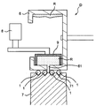
- FIG. 9 is a cross-sectional view showing the device D in the vicinity of the coating roll 6.
- the apparatus D shown in FIG. 9 employs a configuration in which the die 9 is pressed with a predetermined load in the vicinity of the coating roll 6 in the extrusion direction of the material R, and air is used as a member for holding the die 9.
- a cylinder 8 is provided.
- the die 9 is pressed by the air cylinder 8 with a constant load toward the application side of the material R to the optical fiber colored core wire 1 that is in contact with the V groove 71 of the V groove roll 7.
- the material R is applied from the application hole 61.
- an elastic member such as a spring may be provided.
- the optical fiber ribbon 2 according to the present invention described above contains a polyol having a weight average molecular weight of 2500 to 4000 with respect to the material (ultraviolet curable resin composition) constituting the intermittent connection portion 3, It is set as the structure containing a cellulose nanofiber in the specific range.
- the scattering of the material can be suppressed by the centrifugal force generated with the rotation of the coating roll 6 or the like that applies the material at the time of manufacture, and the coating amount on the optical fiber colored core wire 1 can be stabilized. And it becomes the optical fiber tape core wire 2 which can maintain suppression of this scattering etc. even in the manufacture which made the linear velocity high.
- optical fiber cable 4 provided with the optical fiber ribbon 2 according to the present invention enjoys the effect of the optical fiber ribbon 2 described above. That is, the scattering of the material by the coating roll 6 etc. at the time of manufacture of the intermittent connection part 3 can be suppressed, the coating amount to the optical fiber colored core wire 1 can be stabilized, and the line speed can be increased to suppress such scattering.
- An optical fiber cable 4 having an optical fiber ribbon 2 that can be maintained even during manufacture is provided.
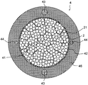
- FIG. 10 is a diagram illustrating an aspect of the optical fiber cable 4.
- a predetermined number (25 in FIG. 10) of optical fiber units 21 obtained by twisting or bundling a predetermined number (8 in FIG. 10) of optical fiber tape cores 2 having a predetermined number of cores are twisted or bundled.
- the cable core 41 is configured.
- a buffer layer 42 made of, for example, a non-woven presser tape or the like is formed around the cable core 41.
- two steel wires (tension members) 43 and two tear strings 44 are formed around the buffer layer 42.
- a covering layer (sheath) 46 made of a thermoplastic resin or the like is formed.
- FIG. 11 is a diagram showing another aspect of the optical fiber cable 4.
- the optical fiber cable 4 in FIG. 11 has a predetermined number of optical fiber units 21 formed by twisting or bundling a predetermined number of optical fiber ribbons 2 (not shown in FIG. 11) with a predetermined number of cores.
- the loose tube 5 is incorporated in a twisted or bundled state, and the optical fiber unit 21 and the loose tube 5 incorporating the optical fiber unit 21 are arranged around a steel wire (tension member) 43 in a predetermined number. (8 in FIG. 11) Twist together.
- a buffer layer 42 made of, for example, a non-woven presser tape or the like is formed around the periphery, and a predetermined number (15 in FIG. 11) of optical fiber units 21 and loose tubes 5 containing the optical fiber units 21 are further provided around the buffer layer 42. ) Arrange and twist.
- a buffer layer 42 made of, for example, a non-woven presser tape and a coating layer (sheath) 46 made of a thermoplastic resin are formed around the periphery.
- FIGS. 10 and 11 For convenience, the hatching of the optical fiber ribbon 2 in FIG. 10 and the optical fiber unit 21 in FIG. 11 is omitted in FIGS. 10 and 11. Moreover, about the code
- the optical fiber cable 4 may be an optical fiber cable such as a center tube type, a loose tube type, or a slot type, and is not particularly limited as long as the optical fiber cable accommodates the optical fiber ribbon 2.
- the coating layer 46 can be, for example, 2.0 to 3.0 mm, but is not particularly limited to this range.
- the configuration of the 12 fibers shown in FIGS. 3 to 5 has been described as an example of the optical fiber ribbon 2, but the number of cores in the optical fiber ribbon 2 (optical fiber coloring) is described.
- the number of cores 1) can be arbitrarily determined in addition to 12 cores, such as 4 cores, 8 cores, and 24 cores.
- the cross-sectional shape of the intermittent connection part 3 although the 2 sides which contact
- the structure shown in FIGS. 10 and 11 has been described as an example of the optical fiber cable 4 including the optical fiber ribbon 2, but the structure of the optical fiber cable 4 is described above.
- the type and thickness of the coating layer 46, the number and size of the optical fiber colored core wire 1 and the optical fiber tape core wire 2, the number and size of the optical fiber units 21, and the optical fiber The number of optical fiber ribbons 2 in the unit 21, the type, number and size of steel wires (tension members) 43, the type and thickness of the buffer layer 42, and the number of layers can be freely selected. .
- the outer diameter, cross-sectional shape, etc. of the optical fiber cable 4 can be freely selected.
- the specific structure, shape, and the like in the implementation of the present invention may be other structures as long as the object of the present invention can be achieved.
- optical fiber colored core wires shown in FIGS. 1 and 2 were provided by the methods shown in (1) and (2) below, as shown in FIGS.
- An optical fiber ribbon having the configuration shown in FIG. 5 was manufactured.
- the molecular weight refers to “weight average molecular weight”.
- the following component was used about the primary coating layer, the secondary coating layer, the colored layer, and the intermittent connection part.
- optical fiber colored core Around an optical fiber made of quartz glass and having an outer diameter of 125 ⁇ m, the outer diameter of the primary coating layer (primary layer) is 195 ⁇ m and the outer diameter of the secondary coating layer (secondary layer) is 242 ⁇ m. The layer was coated into an optical fiber. The obtained optical fiber is coated with a colored layer (the component that becomes the colored layer is component a) around the secondary coating layer in a separate process. An optical fiber colored core wire having a diameter of 255 ⁇ m was obtained.
- optical fiber colored core Around a glass optical fiber made of quartz glass having an outer diameter of 125 ⁇ m, which is an optical fiber, an outer diameter of the primary coating layer (primary layer) is 185 ⁇ m, and a colored secondary coating layer (with a colored secondary coating layer and The component is component b.) The outer diameter was 255 ⁇ m and each layer was coated to obtain an optical fiber colored core wire having an outer diameter of 255 ⁇ m having the configuration shown in FIG.
- the primary coating layer and the secondary coating layer are made of an oligomer using polypropylene glycol as an ultraviolet curable resin (polypropylene glycol as an intermediate block, and skeleton component having hydroxyethyl acrylate as a skeleton component via tolylene diisocyanate. Oligomer)), dilutable monomer, photoinitiator, and additives were mixed and used in appropriate amounts.
- Component a optical fiber colored core wire as shown in FIG. 1:
- the UV curable resin constituting component a (colorant component a) to be a colored layer uses urethane acrylate or bisphenol A epoxy acrylate as an oligomer, and a Young's modulus by adding a bifunctional monomer or a polyfunctional monomer as a monomer. Adjusted. Moreover, 3 mass% of both terminal type acrylic modified silicone was contained with respect to the whole colored layer.
- Photoinitiators are 2-methyl-1- (4-methylthiophenyl) -2-morpholinopropan-1-one (Irgacure 907), 2,4,6-trimethylbenzoyl-diphenyl-phosphine oxide (lucillin TPO), 2,4-Diethylthioxanthone (Kayacure DETX-S) was added.
- the oxygen concentration in the production was adjusted to 3 to 5%, and the ultraviolet irradiation amount was 80 mJ / cm 2 or less.
- Component b optical fiber colored core wire as shown in FIG. 2:
- the ultraviolet curable resin constituting component b (coloring material component b) to be a colored secondary coating layer (colored layer) is obtained by adding aromatic isocyanate and hydroxyethyl acrylate to a polyol using polypropylene glycol as an oligomer.
- the Young's modulus was adjusted by changing the molecular weight of the middle block polyol (polypropylene glycol) or by using a bifunctional monomer or a polyfunctional monomer.
- the material (ultraviolet curable resin composition) constituting the intermittent connection portion as the following material, 600 m / min as follows: (The speed at which the colored optical fiber is advanced; the same shall apply hereinafter) and a predetermined pattern (length of intermittently connected portion: 30 mm, length of non-connected portion: 10 mm, pitch length) was applied while adjusting the resin pressure (application pressure) to be 80 mm) and cured to form intermittently connected portions (and non-connected portions), thereby forming an optical fiber ribbon.
- the viscosity of the material constituting the intermittent connection portion was confirmed by the following method, and the presence or absence of material scattering in the application of the material constituting the intermittent connection portion was confirmed. . Furthermore, the adhesive strength between the optical fiber colored core wire and the intermittent connection portion was also measured.
- Base material used as a component of intermittent connection Oligomer as an ultraviolet curable resin (an oligomer in which a polypropylene glycol having a weight average molecular weight of 2000 is used as an intermediate block and hydroxyethyl acrylate is bonded to hydroxyl groups at both ends as a skeleton component via tolylene diisocyanate). Isobornyl acrylate and PO-modified nonylphenol acrylate were used as monofunctional monomers, and tricyclodecane dimethylol diacrylate and 1,6-hexanediol diacrylate were used as bifunctional monomers.
- photoinitiators 1-hydroxy-cyclohexyl-phenyl-ketone, 2,4,6-trimethylbenzoyl-diphenyl-phosphine oxide was used. Further, a suitable amount of hindered amine light stabilizer and silicone (weight average molecular weight: about 10,000) as light stabilizers were mixed as additives. A material composed of these components is used as a base material, and a polyol (cellulose curable resin composition) that constitutes an intermittently connected portion by adding the following polyols and cellulose nanofibers at a predetermined content (note that In Comparative Example 1, no cellulose nanofiber was added.)
- Example 1 Polypropylene glycol having a weight average molecular weight of 3000 as a polyol (PP3000: manufactured by Sanyo Chemical Industries, Ltd.) is used as the base material, and an ultraviolet curable resin composition (a material constituting the intermittent connection portion). In some cases.) 23 mass% of the total was added. Further, cellulose powder (KC Flock W-200: manufactured by Nippon Paper Chemicals Co., Ltd., powdered cellulose having an average particle diameter of about 32 ⁇ m) is defibrated with a homogenizer, and the size (number average major axis diameter) is 0.007 to 1 ⁇ m. (7 to 1000 nm) was used as cellulose nanofiber (hereinafter the same as in Examples 2 to 5 and Comparative Example 2), and the cellulose nanofiber was 0.01% by mass relative to the entire composition. Added.
- cellulose powder KC Flock W-200: manufactured by Nippon Paper Chemicals Co., Ltd., powdered cellulose having an average particle diameter of about 32
- Example 2 Polypropylene glycol having a weight average molecular weight of 3000 (PP3000: manufactured by Sanyo Chemical Industries, Ltd.) as a polyol was added to the base material in an amount of 23% by mass based on the entire composition. Moreover, 0.1 mass% of cellulose nanofiber was added with respect to the whole composition.
- PP3000 weight average molecular weight of 3000
- Example 3 Polypropylene glycol having a weight average molecular weight of 3000 (PP3000: manufactured by Sanyo Chemical Industries, Ltd.) as a polyol was added to the base material in an amount of 23% by mass based on the entire composition. Moreover, 1.0 mass% of cellulose nanofiber was added with respect to the whole composition.
- PP3000 weight average molecular weight of 3000
- Example 4 Polypropylene glycol having a weight average molecular weight of 3000 (PP3000: manufactured by Sanyo Chemical Industries, Ltd.) as a polyol was added to the base material in an amount of 23% by mass based on the entire composition. Moreover, the cellulose nanofiber was added 5.0 mass% with respect to the whole composition.
- PP3000 weight average molecular weight of 3000
- cellulose nanofiber was added 5.0 mass% with respect to the whole composition.
- Example 5 Polypropylene glycol having a weight average molecular weight of 3000 (PP3000: manufactured by Sanyo Chemical Industries, Ltd.) as a polyol was added to the base material in an amount of 23% by mass based on the entire composition. Moreover, 10.0 mass% of cellulose nanofibers were added with respect to the whole composition.
- PP3000 weight average molecular weight of 3000
- the viscosity was measured using a rheometer (MCR301: Anton Paar). The viscosity at a shear rate of 10 1 1 / s (viscosity 25 ° C. 10 ⁇ 1 1 / s) determined from dynamic viscoelasticity at 25 ⁇ parallel plate, gap 0.5 mm, 25 ° C. was determined.
- Table 1 shows the evaluation results. Examples 1 to 5 in which the intermittent connection part contains a polyol having a weight average molecular weight of 2500 to 4000 and the cellulose nanofiber is 0.01 to 10.0% by mass with respect to the entire intermittent connection part.
- material scattering confirmation even when the material scattering confirmation was performed at a linear speed of 600 m / min, it could be determined that the coating amount was stable, and the overall judgment was “ ⁇ ”.
- the material constituting the intermittent connection portion results of viscosity measured in (ultraviolet curable resin composition applied), the viscosity of the shear rate 10 1 1 / s to both determined from a dynamic viscoelasticity at 25 ° C. 2 It was within the range of 0.0 to 8.2 Pa ⁇ s.
- Comparative Example 1 that does not contain cellulose nanofibers in the entire intermittent connection part
- Comparative Example 2 that contains cellulose nanofibers in excess of 10.0% by mass with respect to the entire intermittent connection part
- the measurement results of the adhesive strength are also shown in Table 1.
- Examples 1 to 5 as a result of measuring the adhesive strength of the material constituting the intermittently connected portion of the optical fiber colored core wire (the UV curable resin composition to be applied), production of a high linear velocity (600 m / min) was performed. However, a high adhesive strength of 0.1 N or more was obtained.
- Comparative Example 1 shows a result of low adhesive strength (lower than 0.1N), and Comparative Example 2 does not follow the linear velocity, so that a satisfactory optical fiber ribbon cannot be produced, and adhesive strength is obtained.
- Comparative Example 1 shows a result of low adhesive strength (lower than 0.1N)
- Comparative Example 2 does not follow the linear velocity, so that a satisfactory optical fiber ribbon cannot be produced, and adhesive strength is obtained.
- adhesive strength is obtained.
- optical fiber cable 18 (or 36) optical fiber units in which 8 pieces of 12 optical fiber ribbons were twisted were twisted to form a cable core, and a nonwoven fabric holding tape was wound around it as a buffer layer. Furthermore, a coating layer was formed on the outer periphery of the buffer layer together with FRP of ⁇ 4 mm, two steel wires, and two tear strings. Regarding cable formation, a thermoplastic resin was coated as a coating layer (sheath) to form a cable.
- the optical fiber ribbon of the present invention could be cabled in the same manner as a conventional optical fiber ribbon and could be suitably used as an optical fiber cable.
- the present invention can be effectively used as a means for providing an optical fiber ribbon and an optical fiber cable that can prevent scattering of the material constituting the intermittent connection portion during manufacturing, and has high industrial applicability.
- Optical fiber colored core wire 10 ...
- Optical fiber (glass optical fiber) 11 Primary coating layer (primary layer) 12 ; Secondary coating layer (secondary layer) 12a: Colored secondary coating layer 13: Colored layer 2:
- Optical fiber tape core wire 21 Optical fiber unit 3: Intermittent connection part 31, 32: Intermittent connection part 33, X: Non-connection Part (single core) 4 ...
Landscapes
- Physics & Mathematics (AREA)
- General Physics & Mathematics (AREA)
- Optics & Photonics (AREA)
- Engineering & Computer Science (AREA)
- Manufacturing & Machinery (AREA)
- Optical Fibers, Optical Fiber Cores, And Optical Fiber Bundles (AREA)
Abstract
Priority Applications (4)
| Application Number | Priority Date | Filing Date | Title |
|---|---|---|---|
| CN201980017959.7A CN111868592A (zh) | 2018-03-08 | 2019-03-08 | 光纤带芯线和光纤线缆 |
| JP2020504069A JPWO2019172444A1 (ja) | 2018-03-08 | 2019-03-08 | 光ファイバテープ心線及び光ファイバケーブル |
| EP19764993.2A EP3764142A4 (fr) | 2018-03-08 | 2019-03-08 | Ruban de fibre optique et câble à fibres optiques |
| US17/014,892 US20200400904A1 (en) | 2018-03-08 | 2020-09-08 | Optical fiber ribbon and optical fiber cable |
Applications Claiming Priority (2)
| Application Number | Priority Date | Filing Date | Title |
|---|---|---|---|
| JP2018-041423 | 2018-03-08 | ||
| JP2018041423 | 2018-03-08 |
Related Child Applications (1)
| Application Number | Title | Priority Date | Filing Date |
|---|---|---|---|
| US17/014,892 Continuation US20200400904A1 (en) | 2018-03-08 | 2020-09-08 | Optical fiber ribbon and optical fiber cable |
Publications (1)
| Publication Number | Publication Date |
|---|---|
| WO2019172444A1 true WO2019172444A1 (fr) | 2019-09-12 |
Family
ID=67846719
Family Applications (1)
| Application Number | Title | Priority Date | Filing Date |
|---|---|---|---|
| PCT/JP2019/009482 Ceased WO2019172444A1 (fr) | 2018-03-08 | 2019-03-08 | Ruban de fibre optique et câble à fibres optiques |
Country Status (5)
| Country | Link |
|---|---|
| US (1) | US20200400904A1 (fr) |
| EP (1) | EP3764142A4 (fr) |
| JP (1) | JPWO2019172444A1 (fr) |
| CN (1) | CN111868592A (fr) |
| WO (1) | WO2019172444A1 (fr) |
Cited By (3)
| Publication number | Priority date | Publication date | Assignee | Title |
|---|---|---|---|---|
| JPWO2022065485A1 (fr) * | 2020-09-28 | 2022-03-31 | ||
| JP2022108476A (ja) * | 2021-01-13 | 2022-07-26 | 古河電気工業株式会社 | 光ファイバテープ心線及び光ファイバケーブル |
| JP2023017384A (ja) * | 2021-07-26 | 2023-02-07 | 古河電気工業株式会社 | 間欠接着型光ファイバテープ心線、光ファイバケーブル、間欠接着型光ファイバテープ心線の製造方法 |
Families Citing this family (4)
| Publication number | Priority date | Publication date | Assignee | Title |
|---|---|---|---|---|
| US11442238B2 (en) * | 2020-12-22 | 2022-09-13 | Prysmian S.P.A. | Optical-fiber ribbon with spaced optical-fiber units |
| CN112876099B (zh) * | 2021-02-01 | 2024-02-20 | 山东鹰联光电科技股份有限公司 | 一种集中式光纤着色v形集线模具及其着色工艺 |
| CN114199460B (zh) * | 2021-12-13 | 2024-09-24 | 武汉理工大学 | 基于光栅阵列传感技术的覆土油罐泄漏监测方法及系统 |
| CN114217397B (zh) * | 2021-12-20 | 2023-03-21 | 长飞光纤光缆股份有限公司 | 光纤带的成型方法及专用于实施该成型方法的点胶设备 |
Citations (15)
| Publication number | Priority date | Publication date | Assignee | Title |
|---|---|---|---|---|
| JPS5117519B1 (fr) | 1975-02-28 | 1976-06-02 | ||
| JPS5149230B2 (fr) | 1971-09-27 | 1976-12-25 | ||
| JP2001264604A (ja) | 2000-03-21 | 2001-09-26 | Fujikura Ltd | 光ファイバテープ心線の製造装置 |
| WO2011126038A1 (fr) * | 2010-04-06 | 2011-10-13 | ユニチカ株式会社 | Composition de résine polyamide et procédé de production d'une composition de résine polyamide |
| JP2014142631A (ja) * | 2012-12-28 | 2014-08-07 | Daicel Corp | 高分子光ファイバーの製造方法及び該方法により製造された高分子光ファイバー |
| JP2015000934A (ja) * | 2013-06-14 | 2015-01-05 | 花王株式会社 | 樹脂組成物及びその製造方法 |
| JP2016133606A (ja) * | 2015-01-19 | 2016-07-25 | 古河電気工業株式会社 | 光ファイバテープ心線、光ファイバテープ心線の分割方法 |
| US20160245990A1 (en) * | 2015-02-20 | 2016-08-25 | Elwha Llc | Biodegradable optical fibers and methods of use thereof |
| WO2017094560A1 (fr) * | 2015-12-01 | 2017-06-08 | 古河電気工業株式会社 | Fil central de ruban de fibre optique et câble à fibres optiques |
| JP6169060B2 (ja) | 2014-10-16 | 2017-07-26 | 古河電気工業株式会社 | 光ファイバテープ心線の製造方法、光ファイバテープ心線の製造装置 |
| JP2017156558A (ja) * | 2016-03-02 | 2017-09-07 | 古河電気工業株式会社 | 光ファイバケーブルの製造方法、光ファイバテープ心線の製造方法 |
| JP6211160B1 (ja) * | 2016-09-30 | 2017-10-11 | 大王製紙株式会社 | 水解性シート |
| JP2017204931A (ja) * | 2016-05-11 | 2017-11-16 | 住友電装株式会社 | 電線束用外装シート、電線束用保護筒体およびワイヤハーネス |
| WO2018012643A1 (fr) * | 2016-07-15 | 2018-01-18 | スターライト工業株式会社 | Composition de résine et procédé pour sa production |
| JP2018098064A (ja) * | 2016-12-14 | 2018-06-21 | 住友電気工業株式会社 | 絶縁電線 |
Family Cites Families (2)
| Publication number | Priority date | Publication date | Assignee | Title |
|---|---|---|---|---|
| TW420757B (en) * | 1996-11-18 | 2001-02-01 | Sumitomo Electric Industries | Divided type optical fiber tape core wires |
| US10989888B2 (en) * | 2016-02-02 | 2021-04-27 | Ofs Fitel, Llc | Flexible ribbon structure and method for making |
-
2019
- 2019-03-08 WO PCT/JP2019/009482 patent/WO2019172444A1/fr not_active Ceased
- 2019-03-08 CN CN201980017959.7A patent/CN111868592A/zh active Pending
- 2019-03-08 JP JP2020504069A patent/JPWO2019172444A1/ja active Pending
- 2019-03-08 EP EP19764993.2A patent/EP3764142A4/fr not_active Withdrawn
-
2020
- 2020-09-08 US US17/014,892 patent/US20200400904A1/en not_active Abandoned
Patent Citations (15)
| Publication number | Priority date | Publication date | Assignee | Title |
|---|---|---|---|---|
| JPS5149230B2 (fr) | 1971-09-27 | 1976-12-25 | ||
| JPS5117519B1 (fr) | 1975-02-28 | 1976-06-02 | ||
| JP2001264604A (ja) | 2000-03-21 | 2001-09-26 | Fujikura Ltd | 光ファイバテープ心線の製造装置 |
| WO2011126038A1 (fr) * | 2010-04-06 | 2011-10-13 | ユニチカ株式会社 | Composition de résine polyamide et procédé de production d'une composition de résine polyamide |
| JP2014142631A (ja) * | 2012-12-28 | 2014-08-07 | Daicel Corp | 高分子光ファイバーの製造方法及び該方法により製造された高分子光ファイバー |
| JP2015000934A (ja) * | 2013-06-14 | 2015-01-05 | 花王株式会社 | 樹脂組成物及びその製造方法 |
| JP6169060B2 (ja) | 2014-10-16 | 2017-07-26 | 古河電気工業株式会社 | 光ファイバテープ心線の製造方法、光ファイバテープ心線の製造装置 |
| JP2016133606A (ja) * | 2015-01-19 | 2016-07-25 | 古河電気工業株式会社 | 光ファイバテープ心線、光ファイバテープ心線の分割方法 |
| US20160245990A1 (en) * | 2015-02-20 | 2016-08-25 | Elwha Llc | Biodegradable optical fibers and methods of use thereof |
| WO2017094560A1 (fr) * | 2015-12-01 | 2017-06-08 | 古河電気工業株式会社 | Fil central de ruban de fibre optique et câble à fibres optiques |
| JP2017156558A (ja) * | 2016-03-02 | 2017-09-07 | 古河電気工業株式会社 | 光ファイバケーブルの製造方法、光ファイバテープ心線の製造方法 |
| JP2017204931A (ja) * | 2016-05-11 | 2017-11-16 | 住友電装株式会社 | 電線束用外装シート、電線束用保護筒体およびワイヤハーネス |
| WO2018012643A1 (fr) * | 2016-07-15 | 2018-01-18 | スターライト工業株式会社 | Composition de résine et procédé pour sa production |
| JP6211160B1 (ja) * | 2016-09-30 | 2017-10-11 | 大王製紙株式会社 | 水解性シート |
| JP2018098064A (ja) * | 2016-12-14 | 2018-06-21 | 住友電気工業株式会社 | 絶縁電線 |
Non-Patent Citations (2)
| Title |
|---|
| "Research and development of highly functional green members for automobiles by cellulose nanofiber reinforcement", FY 1990-FY 2004 ACHIEVEMENT REPORT, 22 February 2013 (2013-02-22), JP, pages 1 - 84, XP009523566 * |
| See also references of EP3764142A4 |
Cited By (6)
| Publication number | Priority date | Publication date | Assignee | Title |
|---|---|---|---|---|
| JPWO2022065485A1 (fr) * | 2020-09-28 | 2022-03-31 | ||
| WO2022065485A1 (fr) * | 2020-09-28 | 2022-03-31 | 住友電気工業株式会社 | Câble à fibres optiques et câble avec connecteur |
| JP2022108476A (ja) * | 2021-01-13 | 2022-07-26 | 古河電気工業株式会社 | 光ファイバテープ心線及び光ファイバケーブル |
| JP7335903B2 (ja) | 2021-01-13 | 2023-08-30 | 古河電気工業株式会社 | 光ファイバテープ心線及び光ファイバケーブル |
| JP2023017384A (ja) * | 2021-07-26 | 2023-02-07 | 古河電気工業株式会社 | 間欠接着型光ファイバテープ心線、光ファイバケーブル、間欠接着型光ファイバテープ心線の製造方法 |
| JP7704606B2 (ja) | 2021-07-26 | 2025-07-08 | 古河電気工業株式会社 | 間欠接着型光ファイバテープ心線、光ファイバケーブル、間欠接着型光ファイバテープ心線の製造方法 |
Also Published As
| Publication number | Publication date |
|---|---|
| US20200400904A1 (en) | 2020-12-24 |
| EP3764142A4 (fr) | 2021-11-17 |
| JPWO2019172444A1 (ja) | 2021-03-11 |
| CN111868592A (zh) | 2020-10-30 |
| EP3764142A1 (fr) | 2021-01-13 |
Similar Documents
| Publication | Publication Date | Title |
|---|---|---|
| WO2019172444A1 (fr) | Ruban de fibre optique et câble à fibres optiques | |
| JP7288429B2 (ja) | 光ファイバテープ心線及び光ファイバケーブル | |
| JP6490805B2 (ja) | 光ファイバテープ心線及び光ファイバケーブル | |
| US9488774B2 (en) | Primary optical fiber coating composition containing non-radiation curable component | |
| US9678247B2 (en) | Primary optical fiber coating composition containing non-radiation curable component | |
| JP2014219550A (ja) | 光ファイバ心線 | |
| JP2005503593A (ja) | 感圧接着剤の特性を持つ光ファイバコーティング | |
| DE3239818A1 (de) | Beschichtete optische faser und verfahren zu deren herstellung | |
| CN114845968B (zh) | 树脂组合物、光纤以及光纤的制造方法 | |
| JP6046021B2 (ja) | オーバーコート心線及び当該オーバーコート心線を備えた光ファイバケーブル | |
| US4909597A (en) | Flexible optical waveguide containing a thermoplastic aliphatic segmented polyurethane core | |
| TW202233708A (zh) | 樹脂組合物、樹脂組合物之製造方法、光纖、光纖之製造方法、光纖帶、及光纖纜 | |
| JP5787927B2 (ja) | オーバーコート心線及び当該オーバーコート心線を備えた光ファイバケーブル | |
| JP7335903B2 (ja) | 光ファイバテープ心線及び光ファイバケーブル | |
| RU2320590C2 (ru) | Оптическое волокно с отвержденным полимерным покрытием | |
| CN117046221B (zh) | 一种可降解复合纤维制备滤芯的方法 | |
| DE10333941A1 (de) | Schlichte zur Behandlung von Glasfasern sowie mit diesen Schlichten ausgerüstete Glasfasern | |
| JP5871435B2 (ja) | オーバーコート心線及び当該オーバーコート心線を備えた光ファイバケーブル | |
| CN120936583A (zh) | 树脂组合物、光纤、光纤的制造方法、光纤带、及光纤线缆 |
Legal Events
| Date | Code | Title | Description |
|---|---|---|---|
| 121 | Ep: the epo has been informed by wipo that ep was designated in this application |
Ref document number: 19764993 Country of ref document: EP Kind code of ref document: A1 |
|
| ENP | Entry into the national phase |
Ref document number: 2020504069 Country of ref document: JP Kind code of ref document: A |
|
| NENP | Non-entry into the national phase |
Ref country code: DE |
|
| WWE | Wipo information: entry into national phase |
Ref document number: 2019764993 Country of ref document: EP |
|
| ENP | Entry into the national phase |
Ref document number: 2019764993 Country of ref document: EP Effective date: 20201008 |