WO2019176126A1 - 検査チップおよび検査装置 - Google Patents
検査チップおよび検査装置 Download PDFInfo
- Publication number
- WO2019176126A1 WO2019176126A1 PCT/JP2018/020224 JP2018020224W WO2019176126A1 WO 2019176126 A1 WO2019176126 A1 WO 2019176126A1 JP 2018020224 W JP2018020224 W JP 2018020224W WO 2019176126 A1 WO2019176126 A1 WO 2019176126A1
- Authority
- WO
- WIPO (PCT)
- Prior art keywords
- microneedle
- inspection
- inspection chip
- blood
- main body
- Prior art date
- Legal status (The legal status is an assumption and is not a legal conclusion. Google has not performed a legal analysis and makes no representation as to the accuracy of the status listed.)
- Ceased
Links
Images



Classifications
-
- A—HUMAN NECESSITIES
- A61—MEDICAL OR VETERINARY SCIENCE; HYGIENE
- A61B—DIAGNOSIS; SURGERY; IDENTIFICATION
- A61B5/00—Measuring for diagnostic purposes; Identification of persons
- A61B5/15—Devices for taking samples of blood
- A61B5/150007—Details
- A61B5/150015—Source of blood
- A61B5/150022—Source of blood for capillary blood or interstitial fluid
-
- A—HUMAN NECESSITIES
- A61—MEDICAL OR VETERINARY SCIENCE; HYGIENE
- A61B—DIAGNOSIS; SURGERY; IDENTIFICATION
- A61B5/00—Measuring for diagnostic purposes; Identification of persons
- A61B5/145—Measuring characteristics of blood in vivo, e.g. gas concentration or pH-value ; Measuring characteristics of body fluids or tissues, e.g. interstitial fluid or cerebral tissue
- A61B5/14532—Measuring characteristics of blood in vivo, e.g. gas concentration or pH-value ; Measuring characteristics of body fluids or tissues, e.g. interstitial fluid or cerebral tissue for measuring glucose, e.g. by tissue impedance measurement
-
- A—HUMAN NECESSITIES
- A61—MEDICAL OR VETERINARY SCIENCE; HYGIENE
- A61B—DIAGNOSIS; SURGERY; IDENTIFICATION
- A61B5/00—Measuring for diagnostic purposes; Identification of persons
- A61B5/15—Devices for taking samples of blood
- A61B5/150007—Details
- A61B5/150206—Construction or design features not otherwise provided for; manufacturing or production; packages; sterilisation of piercing element, piercing device or sampling device
- A61B5/150274—Manufacture or production processes or steps for blood sampling devices
- A61B5/150282—Manufacture or production processes or steps for blood sampling devices for piercing elements, e.g. blade, lancet, canula, needle
-
- A—HUMAN NECESSITIES
- A61—MEDICAL OR VETERINARY SCIENCE; HYGIENE
- A61B—DIAGNOSIS; SURGERY; IDENTIFICATION
- A61B5/00—Measuring for diagnostic purposes; Identification of persons
- A61B5/15—Devices for taking samples of blood
- A61B5/150007—Details
- A61B5/150358—Strips for collecting blood, e.g. absorbent
-
- A—HUMAN NECESSITIES
- A61—MEDICAL OR VETERINARY SCIENCE; HYGIENE
- A61B—DIAGNOSIS; SURGERY; IDENTIFICATION
- A61B5/00—Measuring for diagnostic purposes; Identification of persons
- A61B5/15—Devices for taking samples of blood
- A61B5/150007—Details
- A61B5/150374—Details of piercing elements or protective means for preventing accidental injuries by such piercing elements
- A61B5/150381—Design of piercing elements
- A61B5/150412—Pointed piercing elements, e.g. needles, lancets for piercing the skin
- A61B5/150419—Pointed piercing elements, e.g. needles, lancets for piercing the skin comprising means for capillary action
-
- A—HUMAN NECESSITIES
- A61—MEDICAL OR VETERINARY SCIENCE; HYGIENE
- A61B—DIAGNOSIS; SURGERY; IDENTIFICATION
- A61B5/00—Measuring for diagnostic purposes; Identification of persons
- A61B5/15—Devices for taking samples of blood
- A61B5/150969—Low-profile devices which resemble patches or plasters, e.g. also allowing collection of blood samples for testing
-
- A—HUMAN NECESSITIES
- A61—MEDICAL OR VETERINARY SCIENCE; HYGIENE
- A61B—DIAGNOSIS; SURGERY; IDENTIFICATION
- A61B5/00—Measuring for diagnostic purposes; Identification of persons
- A61B5/15—Devices for taking samples of blood
- A61B5/150977—Arrays of piercing elements for simultaneous piercing
- A61B5/150984—Microneedles or microblades
-
- A—HUMAN NECESSITIES
- A61—MEDICAL OR VETERINARY SCIENCE; HYGIENE
- A61B—DIAGNOSIS; SURGERY; IDENTIFICATION
- A61B5/00—Measuring for diagnostic purposes; Identification of persons
- A61B5/15—Devices for taking samples of blood
- A61B5/155—Devices specially adapted for continuous or multiple sampling, e.g. at predetermined intervals
-
- A—HUMAN NECESSITIES
- A61—MEDICAL OR VETERINARY SCIENCE; HYGIENE
- A61B—DIAGNOSIS; SURGERY; IDENTIFICATION
- A61B5/00—Measuring for diagnostic purposes; Identification of persons
- A61B5/68—Arrangements of detecting, measuring or recording means, e.g. sensors, in relation to patient
- A61B5/6846—Arrangements of detecting, measuring or recording means, e.g. sensors, in relation to patient specially adapted to be brought in contact with an internal body part, i.e. invasive
- A61B5/6847—Arrangements of detecting, measuring or recording means, e.g. sensors, in relation to patient specially adapted to be brought in contact with an internal body part, i.e. invasive mounted on an invasive device
- A61B5/685—Microneedles
-
- A—HUMAN NECESSITIES
- A61—MEDICAL OR VETERINARY SCIENCE; HYGIENE
- A61B—DIAGNOSIS; SURGERY; IDENTIFICATION
- A61B2562/00—Details of sensors; Constructional details of sensor housings or probes; Accessories for sensors
- A61B2562/02—Details of sensors specially adapted for in-vivo measurements
-
- A—HUMAN NECESSITIES
- A61—MEDICAL OR VETERINARY SCIENCE; HYGIENE
- A61B—DIAGNOSIS; SURGERY; IDENTIFICATION
- A61B5/00—Measuring for diagnostic purposes; Identification of persons
- A61B5/15—Devices for taking samples of blood
- A61B5/157—Devices characterised by integrated means for measuring characteristics of blood
-
- A—HUMAN NECESSITIES
- A61—MEDICAL OR VETERINARY SCIENCE; HYGIENE
- A61M—DEVICES FOR INTRODUCING MEDIA INTO, OR ONTO, THE BODY; DEVICES FOR TRANSDUCING BODY MEDIA OR FOR TAKING MEDIA FROM THE BODY; DEVICES FOR PRODUCING OR ENDING SLEEP OR STUPOR
- A61M37/00—Other apparatus for introducing media into the body; Percutany, i.e. introducing medicines into the body by diffusion through the skin
- A61M37/0015—Other apparatus for introducing media into the body; Percutany, i.e. introducing medicines into the body by diffusion through the skin by using microneedles
- A61M2037/0053—Methods for producing microneedles
-
- A—HUMAN NECESSITIES
- A61—MEDICAL OR VETERINARY SCIENCE; HYGIENE
- A61M—DEVICES FOR INTRODUCING MEDIA INTO, OR ONTO, THE BODY; DEVICES FOR TRANSDUCING BODY MEDIA OR FOR TAKING MEDIA FROM THE BODY; DEVICES FOR PRODUCING OR ENDING SLEEP OR STUPOR
- A61M37/00—Other apparatus for introducing media into the body; Percutany, i.e. introducing medicines into the body by diffusion through the skin
- A61M37/0015—Other apparatus for introducing media into the body; Percutany, i.e. introducing medicines into the body by diffusion through the skin by using microneedles
- A61M2037/0061—Methods for using microneedles
-
- A—HUMAN NECESSITIES
- A61—MEDICAL OR VETERINARY SCIENCE; HYGIENE
- A61M—DEVICES FOR INTRODUCING MEDIA INTO, OR ONTO, THE BODY; DEVICES FOR TRANSDUCING BODY MEDIA OR FOR TAKING MEDIA FROM THE BODY; DEVICES FOR PRODUCING OR ENDING SLEEP OR STUPOR
- A61M37/00—Other apparatus for introducing media into the body; Percutany, i.e. introducing medicines into the body by diffusion through the skin
- A61M37/0015—Other apparatus for introducing media into the body; Percutany, i.e. introducing medicines into the body by diffusion through the skin by using microneedles
Definitions
- the present invention relates to an inspection chip, and more particularly, to an inspection chip including a microneedle and an inspection device including the inspection chip.
- Self-blood glucose measuring devices that are currently on the market measure blood sugar by damaging a capillary such as a finger with a needle and bringing blood oozing from the wound into contact with a sensor. Since this self-blood glucose measuring device is painful at the time of measurement, the burden is great for diabetic patients who measure frequently.
- Microneedle for blood collection is known as a minimally invasive voter without pain.
- a microneedle for blood collection is a hollow needle having a length of about 1 mm, an outer diameter of 100 to 300 ⁇ m, and an inner diameter of 60 to 100 ⁇ m.
- a metal such as nickel or a photoresist has been proposed.
- Patent Document 1 describes a blood monitoring system including a microneedle for blood collection.
- the microneedle for blood collection is difficult to manufacture due to its structure and dimensions. Furthermore, if the strength is not sufficient, it may break in the body and remain in the skin. In addition, in order to more accurately grasp the medical condition of a diabetic patient, it is important to continuously monitor blood glucose.
- the blood monitoring system described in Patent Document 1 has a structure that sucks blood continuously. Because it is not, this request cannot be met.
- various mechanisms such as a pump and a power source for driving the pump are required, the apparatus becomes large, and the manufacturing cost increases. To do.
- An object of this invention is to provide the test
- Another object of the present invention is to provide a test apparatus capable of continuously monitoring a substance in blood with minimal invasiveness.
- a first aspect of the present invention is provided at a position overlapping with an inflow hole, a base plate having a microchannel connected to the inflow hole, a reaction chamber connected to the microchannel, and a biodegradable A test chip comprising a porous microneedle formed of a material, a sensor disposed in a reaction chamber, a capillary pump section provided on the base plate and connected to the reaction chamber. It is.
- the second aspect of the present invention is an inspection apparatus provided with the inspection chip of the present invention.
- blood can be continuously acquired with minimal invasiveness, and various tests and monitoring can be performed.
- FIG. 3 is a cross-sectional view taken along line II in FIG. 2. It is sectional drawing which shows typically the microneedle of the test
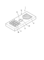
- FIG. 1 is a perspective view showing an inspection chip 1 of the present embodiment.
- the inspection chip 1 includes a base plate 10 having a micro flow channel, and a plurality of microneedles 20 and sensors 19 formed on the base plate 10.
- FIG. 2 is a schematic view in plan view of the base plate 10 before the microneedles 20 are formed.
- a plurality of inflow holes 11 are opened in a region on one end side of the base plate 10.
- a capillary pump portion 16 is formed in the region on the other end side of the base plate 10.
- a single intermediate flow path 17 is formed between the inflow hole 11 and the capillary pump unit 16.
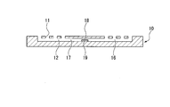
- 3 is a cross-sectional view taken along the line II of FIG.
- a plurality of microchannels 12 are formed in the middle portion of the base plate 10 in the thickness direction. The microchannel 12 communicates with each inflow hole 11.
- the micro flow channel 12 gradually merges as it approaches the capillary pump unit 16 and finally becomes a single flow channel and is connected to the intermediate flow channel 17.
- the capillary pump unit 16 is composed of a large number of small-diameter channels that gradually branch from the intermediate channel 17. As a shape which branches gradually, a shape like a tournament table can be illustrated, for example.
- the width and depth of the small-diameter channel may be appropriately set within a range in which capillary action occurs, and can be, for example, about 2 to 5 ⁇ m.
- the upper part of the capillary pump part 16 may be open or covered with a cover or the like, but at least the terminal part is released to the atmosphere so that the fluid can flow in.
- the microchannel 12 and the capillary pump unit 16 of the base plate 10 can be formed by combining photolithography, reactive ion etching, dry etching using xenon difluoride (XeF 2 ), and the like. From the viewpoint of applying these techniques, the base plate 10 is preferably made of a silicon wafer.
- the intermediate flow path 17 is widened at the intermediate portion and serves as a reaction chamber 18.
- a sensor 19 is installed in the reaction chamber 18.
- the sensor 19 is in a position where it can come into contact with the fluid flowing through the intermediate flow path 17.
- the specific content of the sensor 19 is appropriately determined according to the item to be measured. For example, in the case of blood glucose level measurement, an electrode portion of an electrochemical or optical glucose sensor using glucose oxidase or glucose dehydrogenase can be used.
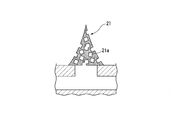
- FIG. 4 is a cross-sectional view of the microneedle 20.
- the microneedle 20 includes a porous main body 21 and a coating 22 that covers the tip of the main body 21.
- the main body 21 is formed of a biodegradable material, and has a large number of holes 21a on the surface and inside.
- the biodegradable material include polylactic acid (PLA), polyglycolic acid (PGA), poly (lactide-co-glycolide) copolymer (PLGA), and the like.
- the microneedle 20 has a substantially conical shape or a substantially pyramid shape, and the diameter or maximum dimension of the base is, for example, about 50 ⁇ m to 200 ⁇ m.
- the height of the microneedle 20 defines the depth of penetration into the skin. In the present embodiment, considering that it reaches the dermis and does not stimulate pain, the thickness is set to 300 ⁇ m or more and 1 mm or less.
- the plurality of holes 21 a formed in the main body 21 are partially in communication with each other inside the main body 21. As a result, a communication path communicating from the side surface to the bottom surface of the main body 21 is formed in the main body 21.
- the size of the hole 21a can be set as appropriate in consideration of the configuration of the fluid to be collected. For example, when the fluid contains solid matter and the solid matter interferes with the measurement performed by the sensor 19, the size of the hole 21a is made smaller than the solid matter, and the solid matter is contained in the base plate 10. Can be configured not to enter.
- the size of the hole 21a can be set to about 30 ⁇ m to 60 ⁇ m in consideration of the size of blood cell components, for example.
- the coating 22 covers the tip portion of the main body 21 and constitutes the sharp tip of the microneedle 20.
- the material of the coating 22 include a material having a high affinity for a living body and having a certain hardness in a dry state, for example, hyaluronic acid.
- a manufacturing procedure of the microneedle 20 will be described.
- the water-soluble particles and the material of the main body 21 are mixed without dissolving the water-soluble particles to adjust the viscous material.
- the size of the water-soluble particles is the same as the size of the holes 21 a formed in the main body 21.
- the amount of water-soluble particles is determined based on the porosity set in the main body 21.
- Sodium chloride is comparatively easy to control the magnitude
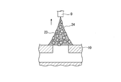
- the adjusted viscous material is filled into a dispenser or the like, and as shown in FIG. 5, the tip of the dispenser D is brought close to the base plate 10 to gently discharge the viscous material.
- a droplet of the viscous material 24 including the water-soluble particles 23 is disposed on the base plate 10.
- the droplet is arranged so as to overlap with the inflow hole 11 on the base plate 10.
- the dispenser D is slowly pulled up and away from the base plate 10
- a part of the droplet follows the dispenser D and is lifted upward.
- the droplet is deformed into a needle-like shape with a sharp top.
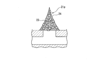
- the prototype 21p is immersed in water to dissolve the water-soluble particles 23.
- the portions where the water-soluble particles 23 exist become holes 21 a, and the main body 21 is completed.
- some of the main bodies 21 are deficient in the tip portion due to dissolution and removal of the water-soluble particles 23 located at the tip portion of the prototype 21p.
- Such a main body 21 cannot be inserted into the skin as it is and does not function as a needle.
- the coating material adheres so as to cover the tip of the main body 21, resulting in a needle-like outer shape. Even when the tip of the main body 21 is missing, the missing material is supplemented with a coating material, and the tip shape is almost the same as when the tip is not missing.
- the attached coating material is dried, as shown in FIG. 9, a coating 22 covering the tip of the main body 21 is formed, and the microneedle 20 is completed.
- the microneedle 20 When the tip of the microneedle 20 is pressed against the user's skin, the microneedle is pierced into the skin from the tip and the whole enters the skin. Since the solidified coating 22 is present at the tip of the microneedle 20, the microneedle 20 has a hardness sufficient to penetrate into the skin. Due to the length of the main body 21, the main body of the microneedle 20 reaches the dermis and does not stimulate pain. As a result, a state in which blood can be collected from the microneedle 20 is established without causing the user to feel pain.
- the air holes 21a of the main body 21 are exposed in the skin and blood can enter.
- the blood that has entered from the air holes 21 a flows through the communication holes in the main body 21 by capillary action, and enters the inflow holes 11 from the bottom opening of the main body 21.
- the blood further flows through the microchannel 12 to the intermediate channel 17, enters the reaction chamber 18, and contacts the sensor 19. Therefore, the sensor 19 can perform a measurement reaction on the blood that has entered, and can acquire an electrical signal obtained as a result.
- the blood that has reached the reaction chamber 18 further flows into the capillary pump unit 16 from the intermediate channel 17 and gradually fills the narrow channel of the capillary pump unit 16. Since the inflow of blood continues until the capillary pump part 16 is completely filled, the sensor 19 can continuously measure until the capillary pump part 16 is filled with blood.
- test chip 1 of the present embodiment it is possible to easily perform a continuous blood test by the patient himself, which has been difficult in the past, without causing the patient to feel any pain.
- the microneedle 20 is formed of a biodegradable material, even if it breaks in the skin due to a user's operation or the like, the microneedle 20 is decomposed and absorbed as it is and does not cause adverse events such as inflammation. . Therefore, the load on the living body is small and extremely safe.
- the inspection chip 1 In the test chip 1, blood is continuously collected by capillary action generated in the capillary pump unit 16, so that blood can be collected continuously without a mechanical pump or its drive source.
- the inspection chip 1 can be configured to be small and easy to handle, and can be manufactured at low cost.
- the time that can be continuously measured by the sensor 19 can be freely adjusted by changing the volume of the capillary pump unit 16, that is, the area of the capillary pump unit 16 in a plan view of the base plate 10. Therefore, it is possible to deal with various forms of continuous measurement according to the target inspection item.
- the microneedle manufacturing method of the present embodiment after forming the prototype 21p of the main body 21 with the biodegradable viscous material 24 containing the water-soluble particles 23, the water-soluble particles 23 are dissolved and removed. Hole 21a is formed. Therefore, by appropriately setting the size of the water-soluble particles to be used, the size and porosity of the pores in the main body 21 to be formed can be controlled with extremely high accuracy. According to the inventor's study using porcine blood, if there are about 15 microneedles 20 with a pore size of 30 to 60 ⁇ m and a porosity of 60 to 80%, it is possible to obtain a sufficient amount of blood necessary for continuous blood glucose measurement I know it. According to the manufacturing method of the present embodiment, a microneedle satisfying such a condition can be reliably and easily manufactured.
- the microneedle 20 is provided with the coating 22 at the tip portion, it is not necessary to consider the size of the hole in order to ensure that the tip portion of the main body is sharp. Therefore, the tip can be sharpened by the coating 22 and the function as a needle can be ensured while setting the optimum pore size and porosity according to the use conditions without restriction. That is, it is possible to achieve both a favorable pore condition and good penetration into the skin at a high level.
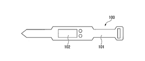
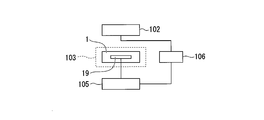
- FIG. 10 is a diagram illustrating an example of an inspection apparatus 100 to which the inspection chip 1 is applied.
- the inspection apparatus 100 includes a wristband 101 and a display screen 102 provided on the wristband 101.
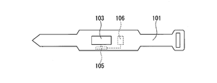
- FIG. 11 is a view showing the back side of the inspection apparatus 100.
- a cavity 103 for fitting the inspection chip 1 is formed on the back side of the wristband 101.
- the microneedle 20 is pressed against the skin with a constant pressure and pierces the skin. After the skin has been pierced and blood sampling has started, the wristband 101 holds the microneedle 20 to prevent it from coming out of the skin, so that blood can be stably acquired.
- FIG. 12 is a block diagram of the inspection apparatus 100.
- the inspection apparatus 100 includes a communication unit 105 capable of wireless communication, and a power source 106 that supplies power to the display screen 102 and the communication unit 105.
- a terminal connected to the sensor 19 is formed on the periphery of the inspection chip 1.
- the sensor 19 and the communication unit 105 are electrically connected by fitting the inspection chip 1 into the cavity 103, and the electrical signal acquired by the sensor 19 is transmitted to an external terminal such as a computer or a mobile phone. Can do.
- a configuration may be adopted in which a removable storage medium is provided instead of the communication unit 105 and the electrical signal acquired by the sensor 19 is stored in the storage medium.
- a configuration in which both a storage medium and a communication unit are provided, and an electrical signal is stored in the storage medium when there is no nearby external terminal capable of communication may be employed. In this case, the storage medium may not be removable.
- the user After the measurement, the user removes the inspection chip 1 from the inspection apparatus 100 and discards it. By inserting a new inspection chip 1 into the cavity 103, it is possible to easily perform repeated inspection.
- a wristwatch type inspection device attached to the wrist is illustrated, but the form of the inspection device is not limited to this, and any shape or attachment is possible as long as the microneedle 20 can be held with a constant pressure against the skin.
- the site is not particularly limited. For example, a clip-like configuration that is used by being sandwiched between earlobes, a patch-like configuration that includes an adhesive portion and is used by being attached to the skin of the abdomen or chest can be exemplified.
- the microneedle in the present invention may be formed by a method other than the method described above. For example, even if the mold is removed after filling the mold in which the shape of the main body is transferred with a biodegradable material mixed with water-soluble particles and joining the base plate 10 at room temperature without pressure, the microneedle is placed on the inflow hole. Can be formed.
- the coating mode can be variously changed. If the coating is made of a material that dissolves quickly in the skin, the coating may cover the entire side of the body. When the coating covers only the tip of the main body, the coating may be made of a biodegradable material and may not necessarily dissolve quickly within the skin. Furthermore, the coating may not be provided as long as the tip of the main body to be formed is in a sharp state due to the relationship between the dimensions of the holes and the main body. That is, the coating is not essential in the microneedle according to the present invention.
- a plurality of sets of intermediate flow paths and reaction chambers may be provided, and different sensors may be arranged for each. If it does in this way, the inspection of a plurality of items can be performed continuously with one inspection chip.
- the acquisition target of the test chip of the present invention is not limited to blood, and various body fluids that can be acquired subcutaneously can be acquired.
- various body fluids that can be acquired subcutaneously can be acquired.
- interstitial fluid and lymph fluid can be obtained, it is possible to deal with a very wide range of examinations by selecting an appropriate sensor and placing it in the reaction chamber.
- the present invention can be applied to an inspection chip and an inspection apparatus.
Landscapes
- Health & Medical Sciences (AREA)
- Life Sciences & Earth Sciences (AREA)
- Engineering & Computer Science (AREA)
- Physics & Mathematics (AREA)
- General Health & Medical Sciences (AREA)
- Biomedical Technology (AREA)
- Heart & Thoracic Surgery (AREA)
- Medical Informatics (AREA)
- Animal Behavior & Ethology (AREA)
- Public Health (AREA)
- Veterinary Medicine (AREA)
- Pathology (AREA)
- Molecular Biology (AREA)
- Surgery (AREA)
- Biophysics (AREA)
- Hematology (AREA)
- Manufacturing & Machinery (AREA)
- Emergency Medicine (AREA)
- Optics & Photonics (AREA)
- Dermatology (AREA)
- Measurement Of The Respiration, Hearing Ability, Form, And Blood Characteristics Of Living Organisms (AREA)
- Media Introduction/Drainage Providing Device (AREA)
- Sampling And Sample Adjustment (AREA)
- Automatic Analysis And Handling Materials Therefor (AREA)
- Anesthesiology (AREA)
Abstract
Description
本願は、2018年3月16日に米国に出願された仮出願62/643,761に基づき優先権を主張し、その内容をここに援用する。
また、糖尿病患者の病状をより的確に把握するためには、持続的に血糖をモニタリングすることが重要であるが、特許文献1に記載の血液監視システムは、持続的に血液を吸引する構造になっていないため、この要望には応えられない。特許文献1に記載の血液監視システムを用いて持続的血糖モニタリングを行おうとすると、ポンプや、ポンプを駆動するための電源などの様々な機構が必要になり、装置が大型化し、製造コストも上昇する。
本発明は、低侵襲で血液を持続的に取得し、検査できる検査チップを提供することを目的とする。
本発明の他の目的は、低侵襲で血中の物質を持続的にモニタリングできる検査装置を提供することである。
図1は、本実施形態の検査チップ1を示す斜視図である。検査チップ1は、マイクロ流路を有するベースプレート10と、ベースプレート10上に形成された複数のマイクロニードル20およびセンサ19とを備えている。
図3は、図2のI-I線における断面図である。ベースプレート10の厚さ方向中間部には、複数のマイクロ流路12が形成されている。マイクロ流路12は、各流入孔11と連通している。マイクロ流路12は、毛細管ポンプ部16に近づくにつれて徐々に合流し、最終的に一本の流路になって中間流路17に接続している。
毛細管ポンプ部16の上部は、開放されていてもカバー等で覆われてもいずれでも構わないが、流体が流入できるよう、少なくとも終端部は大気に解放される。
センサ19の具体的内容は、測定する項目に応じて適宜決定される。例えば、血糖値測定の場合は、グルコース酸化酵素やグルコース脱水素酵素を用いた、電気化学式または光学式のグルコースセンサの電極部分を使用できる。
本体21は、生分解性材料で形成され、表面および内部に多数の空孔21aを有する。生分解性材料としては、例えば、ポリ乳酸(PLA)、ポリグリコール酸(PGA)、ポリ(ラクチド-co-グリコリド)共重合体(PLGA)などを例示できる。
空孔21aの形状には特に制限はない。空孔21aの大きさは、採取する流体の構成等を考慮して、適宜設定できる。例えば、流体が固形物を含んでおり、その固形物がセンサ19で行われる測定の妨げになる場合は、空孔21aの大きさを当該固形物よりも小さくして、ベースプレート10内に固形物が進入しない構成にすることができる。
検査チップ1が血糖測定用である場合、空孔21aの大きさは、例えば、血球成分の大きさを考慮して、30μm~60μm程度とすることができる。
まず、水溶性粒子と本体21の材料とを水溶性粒子を溶解させずに混合し、粘性材料を調整する。水溶性粒子の大きさは、本体21に形成する空孔21aのサイズと同様とする。水溶性粒子の量は、本体21に設定する空隙率に基づいて決定する。水溶性粒子に特に制限はないが、塩化ナトリウムは、比較的粒子の大きさをコントロールしやすく、好適である。
続いて、ディスペンサDをゆっくり引き上げてベースプレート10から遠ざけると、液滴の一部がディスペンサDに追従して上方に引き上げられる。その結果、液滴は、上方がとがった針状の形状に変形する。ディスペンサDをさらに引き上げて液滴から切り離した後、粘性材料24を乾燥させて固化すると、図7に示すように、水溶性粒子23を含んだ本体21の原型21pが形成される。
付着したコーティング材料を乾燥すると、図9に示すように、本体21の先端部を覆うコーティング22が形成され、マイクロニードル20が完成する。
マイクロニードル20の先端を使用者の皮膚に押し当てると、マイクロニードルは、先端から皮膚に刺さり、全体が皮内に進入する。マイクロニードル20の先端には固化したコーティング22が存在するため、皮膚に刺入するのに充分な硬度を有する。本体21の長さにより、マイクロニードル20の本体は、真皮に到達し、かつ痛覚を刺激しない。その結果、マイクロニードル20から血液を採取可能な状態が、使用者に痛みを感じさせることなく確立される。
空孔21aから進入した血液は、毛細管現象により本体21内の連通孔を流れ、本体21の底面開口から流入孔11に進入する。血液は、さらにマイクロ流路12を通って中間流路17に流れ、反応室18内に入ってセンサ19と接触する。したがって、センサ19により、進入した血液に対し測定のための反応を行い、その結果得られた電気信号を取得することができる。
さらに、センサ19で持続的に測定可能な時間は、毛細管ポンプ部16の容積、すなわちベースプレート10の平面視における毛細管ポンプ部16の面積を変更することにより、自由に調節できる。したがって、目的とする検査項目に応じて、様々な態様の持続的測定に対応することができる。
ブタ血液を使った発明者の検討では、空孔寸法30~60μm、空隙率60~80%のマイクロニードル20が15本程度あれば、持続的血糖測定に必要十分な量の血液を取得できることが分かっている。本実施形態の製造方法によれば、このような条件を満たすマイクロニードルを、確実かつ簡便に製造することができる。
図10は、検査チップ1が適用される検査装置100の一例を示す図である。検査装置100は、リストバンド101と、リストバンド101上に設けられた表示画面102とを備えている。
他の態様として、通信部105に代えて取り外し可能な記憶媒体を備え、センサ19の取得した電気信号が記憶媒体に記憶される構成であってもよい。記憶媒体と通信部の両方を備え、通信可能な外部端末が近くにない場合に電気信号を記憶媒体に保存する構成であってもよい。この場合、記憶媒体は取り外し可能でなくてもよい。
上記では、手首に装着する腕時計型の検査装置を例示したが、検査装置の形態はこれには限られず、皮膚に対して一定の圧力でマイクロニードル20を保持できる構成であれば、形状や装着部位は特に限定されない。例えば、耳朶に挟んで使用するクリップ状の構成や、粘着部を備え、腹部や胸部の皮膚に貼り付けて使用するパッチ状の構成などが例示できる。
10 ベースプレート
11 流入孔
12 マイクロ流路
16 毛細管ポンプ部
18 反応室
19 センサ
20 マイクロニードル
21 本体
21a 空孔
22 コーティング
100 検査装置
Claims (6)
- 流入孔と、前記流入孔と接続したマイクロ流路と、前記マイクロ流路と接続された反応室とを有するベースプレートと、
前記流入孔と重なる位置に設けられ、生分解性材料で形成された多孔質のマイクロニードルと、
前記反応室に配置されたセンサと、
細径流路を有し、前記反応室と接続して前記ベースプレートに設けられた毛細管ポンプ部と、
を備える、
検査チップ。 - 前記マイクロニードルは、
前記生分解性材料で形成され、複数の空孔を有する本体と、
前記本体の少なくとも先端部を被覆して皮膚に刺入可能な先端部を形成するコーティングと、を有する、
請求項1に記載の検査チップ。 - 前記コーティングは、皮膚内で溶解する材料で形成されている、
請求項2に記載の検査チップ。 - 前記本体は、前記空孔の寸法が30μm~60μmであり、かつ空隙率が60%~80%である、
請求項2に記載の検査チップ。 - 前記生分解性材料は、ポリ乳酸、ポリグリコール酸、ポリ(ラクチド-co-グリコリド)共重合体の少なくとも一つを含む、
請求項1に記載の検査チップ - 請求項1から5のいずれか一項に記載の検査チップを備える検査装置。
Priority Applications (5)
| Application Number | Priority Date | Filing Date | Title |
|---|---|---|---|
| CN201880091114.8A CN111836582A (zh) | 2018-03-16 | 2018-05-25 | 检测芯片以及检测装置 |
| KR1020207027592A KR102693998B1 (ko) | 2018-03-16 | 2018-05-25 | 검사 칩 및 검사장치 |
| JP2020506108A JP7129720B2 (ja) | 2018-03-16 | 2018-05-25 | 検査チップおよび検査装置 |
| EP18909688.6A EP3766422A4 (en) | 2018-03-16 | 2018-05-25 | Inspection chip and inspection device |
| US17/020,226 US20200405235A1 (en) | 2018-03-16 | 2020-09-14 | Inspection chip and inspection device |
Applications Claiming Priority (2)
| Application Number | Priority Date | Filing Date | Title |
|---|---|---|---|
| US201862643761P | 2018-03-16 | 2018-03-16 | |
| US62/643,761 | 2018-03-16 |
Related Child Applications (1)
| Application Number | Title | Priority Date | Filing Date |
|---|---|---|---|
| US17/020,226 Continuation US20200405235A1 (en) | 2018-03-16 | 2020-09-14 | Inspection chip and inspection device |
Publications (1)
| Publication Number | Publication Date |
|---|---|
| WO2019176126A1 true WO2019176126A1 (ja) | 2019-09-19 |
Family
ID=67906559
Family Applications (2)
| Application Number | Title | Priority Date | Filing Date |
|---|---|---|---|
| PCT/JP2018/020224 Ceased WO2019176126A1 (ja) | 2018-03-16 | 2018-05-25 | 検査チップおよび検査装置 |
| PCT/JP2018/035899 Ceased WO2019176146A1 (ja) | 2018-03-16 | 2018-09-27 | マイクロニードルパッチ及びマイクロニードルパッチの製造方法 |
Family Applications After (1)
| Application Number | Title | Priority Date | Filing Date |
|---|---|---|---|
| PCT/JP2018/035899 Ceased WO2019176146A1 (ja) | 2018-03-16 | 2018-09-27 | マイクロニードルパッチ及びマイクロニードルパッチの製造方法 |
Country Status (6)
| Country | Link |
|---|---|
| US (1) | US20200405235A1 (ja) |
| EP (1) | EP3766422A4 (ja) |
| JP (2) | JP7129720B2 (ja) |
| KR (1) | KR102693998B1 (ja) |
| CN (1) | CN111836582A (ja) |
| WO (2) | WO2019176126A1 (ja) |
Cited By (9)
| Publication number | Priority date | Publication date | Assignee | Title |
|---|---|---|---|---|
| JP2022014362A (ja) * | 2020-07-06 | 2022-01-19 | 国立大学法人東北大学 | マイクロニードル、マイクロニードルアレイ、パッチ、方法 |
| WO2022118859A1 (ja) * | 2020-12-01 | 2022-06-09 | 三井化学株式会社 | マイクロニードルアレイ、マイクロニードルアレイアセンブリ、及び検査チップ |
| JP7141625B1 (ja) | 2021-09-17 | 2022-09-26 | リンテック株式会社 | マイクロニードルパッチ及びマイクロニードル構造体 |
| JPWO2022211058A1 (ja) * | 2021-03-31 | 2022-10-06 | ||
| JPWO2022211059A1 (ja) * | 2021-03-31 | 2022-10-06 | ||
| JPWO2023021665A1 (ja) * | 2021-08-19 | 2023-02-23 | ||
| WO2023048214A1 (ja) * | 2021-09-24 | 2023-03-30 | 三洋化成工業株式会社 | サンプリングシート、検査用シート及び試料採取方法 |
| WO2023190911A1 (ja) * | 2022-03-31 | 2023-10-05 | リンテック株式会社 | マイクロニードル構造体及びマイクロニードル構造体の製造方法 |
| WO2025070573A1 (ja) * | 2023-09-26 | 2025-04-03 | Toppanホールディングス株式会社 | 検査デバイスおよび検査方法 |
Families Citing this family (5)
| Publication number | Priority date | Publication date | Assignee | Title |
|---|---|---|---|---|
| KR102222519B1 (ko) * | 2019-12-31 | 2021-03-04 | 주식회사 이노테라피 | 자기실링이 가능한 안구의 누공억제용 주사바늘 및 그 제조방법 |
| DE102021130954A1 (de) * | 2021-11-25 | 2023-05-25 | Lts Lohmann Therapie-Systeme Ag. | Orales Micronadel Patch |
| KR102761831B1 (ko) * | 2022-04-29 | 2025-02-04 | 서울과학기술대학교 산학협력단 | 마이크로니들 모듈 및 이를 포함하는 마이크로니들 장치 |
| TR2022010005A2 (tr) * | 2022-06-16 | 2022-07-21 | Univ Yildiz Teknik | Transdermal i̇laç salimi i̇çi̇n di̇nami̇k işik i̇şleme yöntemi̇ i̇le mi̇kroi̇ğne üreti̇mi̇ |
| KR102724667B1 (ko) * | 2023-12-14 | 2024-10-31 | 바오밥헬스케어 주식회사 | 마이크로니들이 내재된 환자 맞춤형 창상피복재의 제조방법 및 이에 의해 제조된 마이크로 니들 내재형 환자 맞춤형 창상피복재 |
Citations (5)
| Publication number | Priority date | Publication date | Assignee | Title |
|---|---|---|---|---|
| JP2002078698A (ja) | 2000-07-11 | 2002-03-19 | Bayer Corp | マイクロニードルパッチ、それを用いた血液監視システム及び血液中の化学物質の濃度を測定する方法 |
| JP2005503194A (ja) * | 2001-06-13 | 2005-02-03 | アボット・ラボラトリーズ | 低侵襲的薬物供給のためのマイクロニードルおよびマイクロニードルの製造方法 |
| JP2008079919A (ja) * | 2006-09-28 | 2008-04-10 | Toppan Printing Co Ltd | 針状体および針状体の製造方法 |
| JP2013517102A (ja) * | 2010-01-19 | 2013-05-16 | メドトロニック ミニメド インコーポレイテッド | センサと注入セットとの組み合わせ用の挿入デバイス |
| JP2015530900A (ja) * | 2013-05-22 | 2015-10-29 | アイメック・ヴェーゼットウェーImec Vzw | 小型流体分析デバイスおよび製造方法 |
Family Cites Families (19)
| Publication number | Priority date | Publication date | Assignee | Title |
|---|---|---|---|---|
| EP1345646A2 (en) * | 2000-12-14 | 2003-09-24 | Georgia Tech Research Corporation | Microneedle devices and production thereof |
| US6837988B2 (en) * | 2001-06-12 | 2005-01-04 | Lifescan, Inc. | Biological fluid sampling and analyte measurement devices and methods |
| US8048017B2 (en) | 2005-05-18 | 2011-11-01 | Bai Xu | High-aspect-ratio microdevices and methods for transdermal delivery and sampling of active substances |
| KR20080076434A (ko) * | 2007-02-16 | 2008-08-20 | 박정철 | 생체정보 측정 장치 및 그 제조방법 |
| KR20090059971A (ko) * | 2007-12-07 | 2009-06-11 | 인싸이토 주식회사 | 중공형 마이크로 니들 |
| CN101612092A (zh) | 2009-07-17 | 2009-12-30 | 孙雁群 | 一种粘贴式皮肤针治疗、给药装置 |
| KR101174786B1 (ko) * | 2010-04-07 | 2012-08-17 | 한국메카투라주식회사 | 피부미용 수분민감성 미세바늘패치 및 그 제조방법 |
| US20130158482A1 (en) * | 2010-07-26 | 2013-06-20 | Seventh Sense Biosystems, Inc. | Rapid delivery and/or receiving of fluids |
| BR112013010102A2 (pt) * | 2010-10-25 | 2016-09-06 | Medrx Co Ltd | microagulha, arranjo de microagulhas, dispositivo de microagulhas, e, método para administrar um agente medicinal |
| US20120245445A1 (en) * | 2011-03-21 | 2012-09-27 | Michael Darryl Black | Glucose Monitoring System |
| WO2014152717A2 (en) * | 2013-03-14 | 2014-09-25 | Sano Intelligence, Inc. | On-body microsensor for biomonitoring |
| SG11201600331YA (en) * | 2013-07-16 | 2016-02-26 | 3M Innovative Properties Co | Hollow microneedle with bevel opening |
| JP2015100659A (ja) * | 2013-11-28 | 2015-06-04 | 日本写真印刷株式会社 | マイクロニードルシートの製造方法 |
| JP2015157072A (ja) | 2014-01-27 | 2015-09-03 | コスメディ製薬株式会社 | 3dプリンターによるマイクロニードルの製造 |
| KR101549086B1 (ko) * | 2014-11-10 | 2015-09-02 | 주식회사 스몰랩 | 마이크로 니들 및 마이크로 니들 패치 |
| JP6724792B2 (ja) * | 2015-01-13 | 2020-07-15 | 凸版印刷株式会社 | 経皮投与デバイス |
| KR102426531B1 (ko) * | 2015-03-06 | 2022-07-29 | 삼성전자주식회사 | 생체 정보 측정 장치 및 이의 제작 방법 |
| WO2016195119A1 (ja) * | 2015-06-05 | 2016-12-08 | 国立大学法人東北大学 | マイクロニードル及びマイクロアレイ並びにその製造方法 |
| CN204890943U (zh) * | 2015-08-07 | 2015-12-23 | 北京化工大学 | 一种多段式微针阵列 |
-
2018
- 2018-05-25 CN CN201880091114.8A patent/CN111836582A/zh active Pending
- 2018-05-25 EP EP18909688.6A patent/EP3766422A4/en active Pending
- 2018-05-25 JP JP2020506108A patent/JP7129720B2/ja active Active
- 2018-05-25 WO PCT/JP2018/020224 patent/WO2019176126A1/ja not_active Ceased
- 2018-05-25 KR KR1020207027592A patent/KR102693998B1/ko active Active
- 2018-09-27 JP JP2020506118A patent/JP7141646B2/ja active Active
- 2018-09-27 WO PCT/JP2018/035899 patent/WO2019176146A1/ja not_active Ceased
-
2020
- 2020-09-14 US US17/020,226 patent/US20200405235A1/en active Pending
Patent Citations (5)
| Publication number | Priority date | Publication date | Assignee | Title |
|---|---|---|---|---|
| JP2002078698A (ja) | 2000-07-11 | 2002-03-19 | Bayer Corp | マイクロニードルパッチ、それを用いた血液監視システム及び血液中の化学物質の濃度を測定する方法 |
| JP2005503194A (ja) * | 2001-06-13 | 2005-02-03 | アボット・ラボラトリーズ | 低侵襲的薬物供給のためのマイクロニードルおよびマイクロニードルの製造方法 |
| JP2008079919A (ja) * | 2006-09-28 | 2008-04-10 | Toppan Printing Co Ltd | 針状体および針状体の製造方法 |
| JP2013517102A (ja) * | 2010-01-19 | 2013-05-16 | メドトロニック ミニメド インコーポレイテッド | センサと注入セットとの組み合わせ用の挿入デバイス |
| JP2015530900A (ja) * | 2013-05-22 | 2015-10-29 | アイメック・ヴェーゼットウェーImec Vzw | 小型流体分析デバイスおよび製造方法 |
Non-Patent Citations (1)
| Title |
|---|
| See also references of EP3766422A4 |
Cited By (20)
| Publication number | Priority date | Publication date | Assignee | Title |
|---|---|---|---|---|
| JP2022014362A (ja) * | 2020-07-06 | 2022-01-19 | 国立大学法人東北大学 | マイクロニードル、マイクロニードルアレイ、パッチ、方法 |
| JP7606202B2 (ja) | 2020-07-06 | 2024-12-25 | 国立大学法人東北大学 | マイクロニードル、マイクロニードルアレイ、パッチ、方法 |
| WO2022118859A1 (ja) * | 2020-12-01 | 2022-06-09 | 三井化学株式会社 | マイクロニードルアレイ、マイクロニードルアレイアセンブリ、及び検査チップ |
| KR20230163360A (ko) | 2021-03-31 | 2023-11-30 | 린텍 가부시키가이샤 | 마이크로 니들 구조체의 제조 방법 및 마이크로 니들구조체 |
| JPWO2022211059A1 (ja) * | 2021-03-31 | 2022-10-06 | ||
| WO2022211058A1 (ja) * | 2021-03-31 | 2022-10-06 | リンテック株式会社 | マイクロニードル構造体の製造方法およびマイクロニードル構造体 |
| WO2022211059A1 (ja) * | 2021-03-31 | 2022-10-06 | リンテック株式会社 | マイクロニードル構造体及びその製造方法 |
| JPWO2022211058A1 (ja) * | 2021-03-31 | 2022-10-06 | ||
| CN117083099A (zh) * | 2021-03-31 | 2023-11-17 | 琳得科株式会社 | 微针结构体及其制造方法 |
| JPWO2023021665A1 (ja) * | 2021-08-19 | 2023-02-23 | ||
| WO2023021665A1 (ja) * | 2021-08-19 | 2023-02-23 | 国立大学法人 東京大学 | 多孔質マイクロニードルを備えるパッチ型体液採取及び検査システム、及び当該マイクロニードルを製造する方法 |
| JP7681865B2 (ja) | 2021-08-19 | 2025-05-23 | 国立大学法人 東京大学 | 多孔質マイクロニードルを備えるパッチ型体液採取及び検査システム、及び当該マイクロニードルを製造する方法 |
| JP2023044484A (ja) * | 2021-09-17 | 2023-03-30 | リンテック株式会社 | マイクロニードルパッチ及びマイクロニードル構造体 |
| JPWO2023042525A1 (ja) * | 2021-09-17 | 2023-03-23 | ||
| DE112022004458T5 (de) | 2021-09-17 | 2024-08-22 | Lintec Corporation | Mikronadelpflaster |
| JP7141625B1 (ja) | 2021-09-17 | 2022-09-26 | リンテック株式会社 | マイクロニードルパッチ及びマイクロニードル構造体 |
| WO2023042525A1 (ja) * | 2021-09-17 | 2023-03-23 | リンテック株式会社 | マイクロニードルパッチ |
| WO2023048214A1 (ja) * | 2021-09-24 | 2023-03-30 | 三洋化成工業株式会社 | サンプリングシート、検査用シート及び試料採取方法 |
| WO2023190911A1 (ja) * | 2022-03-31 | 2023-10-05 | リンテック株式会社 | マイクロニードル構造体及びマイクロニードル構造体の製造方法 |
| WO2025070573A1 (ja) * | 2023-09-26 | 2025-04-03 | Toppanホールディングス株式会社 | 検査デバイスおよび検査方法 |
Also Published As
| Publication number | Publication date |
|---|---|
| JP7129720B2 (ja) | 2022-09-02 |
| JPWO2019176146A1 (ja) | 2021-02-25 |
| JP7141646B2 (ja) | 2022-09-26 |
| CN111836582A (zh) | 2020-10-27 |
| KR102693998B1 (ko) | 2024-08-12 |
| US20200405235A1 (en) | 2020-12-31 |
| JPWO2019176126A1 (ja) | 2021-03-11 |
| EP3766422A4 (en) | 2022-03-30 |
| KR20200132889A (ko) | 2020-11-25 |
| EP3766422A1 (en) | 2021-01-20 |
| WO2019176146A1 (ja) | 2019-09-19 |
Similar Documents
| Publication | Publication Date | Title |
|---|---|---|
| JP7129720B2 (ja) | 検査チップおよび検査装置 | |
| US12076518B2 (en) | Rapid delivery and/or receiving of fluids | |
| US20230320661A1 (en) | Rapid delivery and/or withdrawal of fluids | |
| US20210369150A1 (en) | Relatively small devices applied to the skin, modular systems, and methods of use thereof | |
| US7344499B1 (en) | Microneedle device for extraction and sensing of bodily fluids | |
| Chua et al. | Effect of microneedles shape on skin penetration and minimally invasive continuous glucose monitoring in vivo | |
| EP2493537B1 (en) | Systems and methods for treating, sanitizing, and/or shielding the skin or devices applied to the skin | |
| CN101938936B (zh) | 快速血液挤压和采样 | |
| EP2493536B1 (en) | Relatively small devices applied to the skin, modular systems, and methods of use thereof | |
| US20120245445A1 (en) | Glucose Monitoring System | |
| US20120271125A1 (en) | Devices and methods for delivery and/or withdrawal of fluids and preservation of withdrawn fluids | |
| US20110251562A1 (en) | Rapid delivery and/or withdrawal of fluids | |
| US20040138541A1 (en) | Single use analyte sensor | |
| US20110172508A1 (en) | Sampling device interfaces | |
| WO2011163347A2 (en) | Sampling devices and methods involving relatively little pain | |
| JP2007527289A (ja) | 体液サンプリング装置 | |
| WO2000074763A2 (en) | Devices and methods for enhanced microneedle penetration of biological barriers | |
| Yu et al. | An interstitial fluid transdermal extraction system for continuous glucose monitoring | |
| CA2591237A1 (en) | Apparatus and method for continuous real-time trace biomolecular sampling, analysis and delivery | |
| WO2014108087A1 (zh) | 动态连续测定体液中分析物的便携式监测系统 | |
| MXPA06010039A (en) | Body fluid sampling device | |
| WO2014108081A1 (zh) | 微型体液采样器 |
Legal Events
| Date | Code | Title | Description |
|---|---|---|---|
| 121 | Ep: the epo has been informed by wipo that ep was designated in this application |
Ref document number: 18909688 Country of ref document: EP Kind code of ref document: A1 |
|
| ENP | Entry into the national phase |
Ref document number: 2020506108 Country of ref document: JP Kind code of ref document: A |
|
| NENP | Non-entry into the national phase |
Ref country code: DE |
|
| ENP | Entry into the national phase |
Ref document number: 20207027592 Country of ref document: KR Kind code of ref document: A |
|
| WWE | Wipo information: entry into national phase |
Ref document number: 2018909688 Country of ref document: EP |