WO2019176207A1 - Dispositif et procédé de codage d'image mobile, dispositif et procédé de décodage, et système de codage/décodage - Google Patents
Dispositif et procédé de codage d'image mobile, dispositif et procédé de décodage, et système de codage/décodage Download PDFInfo
- Publication number
- WO2019176207A1 WO2019176207A1 PCT/JP2018/046411 JP2018046411W WO2019176207A1 WO 2019176207 A1 WO2019176207 A1 WO 2019176207A1 JP 2018046411 W JP2018046411 W JP 2018046411W WO 2019176207 A1 WO2019176207 A1 WO 2019176207A1
- Authority
- WO
- WIPO (PCT)
- Prior art keywords
- block
- scanning
- aspect ratio
- encoding
- outputting
- Prior art date
- Legal status (The legal status is an assumption and is not a legal conclusion. Google has not performed a legal analysis and makes no representation as to the accuracy of the status listed.)
- Ceased
Links
Images








Classifications
-
- H—ELECTRICITY
- H04—ELECTRIC COMMUNICATION TECHNIQUE
- H04N—PICTORIAL COMMUNICATION, e.g. TELEVISION
- H04N19/00—Methods or arrangements for coding, decoding, compressing or decompressing digital video signals
- H04N19/10—Methods or arrangements for coding, decoding, compressing or decompressing digital video signals using adaptive coding
- H04N19/102—Methods or arrangements for coding, decoding, compressing or decompressing digital video signals using adaptive coding characterised by the element, parameter or selection affected or controlled by the adaptive coding
- H04N19/129—Scanning of coding units, e.g. zig-zag scan of transform coefficients or flexible macroblock ordering [FMO]
-
- H—ELECTRICITY
- H04—ELECTRIC COMMUNICATION TECHNIQUE
- H04N—PICTORIAL COMMUNICATION, e.g. TELEVISION
- H04N19/00—Methods or arrangements for coding, decoding, compressing or decompressing digital video signals
- H04N19/10—Methods or arrangements for coding, decoding, compressing or decompressing digital video signals using adaptive coding
- H04N19/134—Methods or arrangements for coding, decoding, compressing or decompressing digital video signals using adaptive coding characterised by the element, parameter or criterion affecting or controlling the adaptive coding
- H04N19/136—Incoming video signal characteristics or properties
-
- H—ELECTRICITY
- H04—ELECTRIC COMMUNICATION TECHNIQUE
- H04N—PICTORIAL COMMUNICATION, e.g. TELEVISION
- H04N19/00—Methods or arrangements for coding, decoding, compressing or decompressing digital video signals
- H04N19/10—Methods or arrangements for coding, decoding, compressing or decompressing digital video signals using adaptive coding
- H04N19/169—Methods or arrangements for coding, decoding, compressing or decompressing digital video signals using adaptive coding characterised by the coding unit, i.e. the structural portion or semantic portion of the video signal being the object or the subject of the adaptive coding
- H04N19/17—Methods or arrangements for coding, decoding, compressing or decompressing digital video signals using adaptive coding characterised by the coding unit, i.e. the structural portion or semantic portion of the video signal being the object or the subject of the adaptive coding the unit being an image region, e.g. an object
- H04N19/176—Methods or arrangements for coding, decoding, compressing or decompressing digital video signals using adaptive coding characterised by the coding unit, i.e. the structural portion or semantic portion of the video signal being the object or the subject of the adaptive coding the unit being an image region, e.g. an object the region being a block, e.g. a macroblock
-
- H—ELECTRICITY
- H04—ELECTRIC COMMUNICATION TECHNIQUE
- H04N—PICTORIAL COMMUNICATION, e.g. TELEVISION
- H04N19/00—Methods or arrangements for coding, decoding, compressing or decompressing digital video signals
- H04N19/90—Methods or arrangements for coding, decoding, compressing or decompressing digital video signals using coding techniques not provided for in groups H04N19/10-H04N19/85, e.g. fractals
- H04N19/96—Tree coding, e.g. quad-tree coding
Definitions
- the present invention relates to a moving image encoding apparatus and method, decoding apparatus and method, and encoding / decoding system, and more particularly, scanning and decoding for rearranging an array of transform coefficients from two dimensions to one dimension during encoding.
- Encoding apparatus and method, decoding apparatus and method, and encoding capable of realizing high-efficiency encoding and decoding by switching a reverse scanning method for rearranging from one dimension to two dimensions depending on the aspect ratio of the block / Decoding system.
- Patent Documents 1 and 2 propose a mode-dependent scanning method that adaptively selects a scanning order of transform coefficients based on a block size and an intra prediction mode. Specifically, in Patent Documents 1 and 2, when entropy encoding orthogonal transform coefficients of a prediction residual signal block, non-zero transform coefficients are used so that the amount of information of transform coefficients is smaller than that before encoding. The transform coefficients are rearranged in accordance with the occurrence probability of the transform block or for each block size and intra prediction mode of the transform block.
- the transform coefficient scanning method of the prediction residual signal block is the block size of the transform block used when orthogonal transform is performed with the intra prediction mode used when the block is predicted. Specified based on. However, since this method was devised for square blocks, an efficient scanning order is not always specified for non-square blocks.
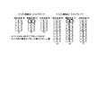
- FIG. 19 shows that when the block size is large and the aspect ratio is large, the order in the one-dimensional arrangement is separated between adjacent sub-blocks depending on the scanning method.
- a sub-block means a 4 ⁇ 4 pixel block.
- HEVC a plurality of scanning methods different for each sub-block are specified as one scanning method, and the scanning method is a scanning of the block itself. It is also used recursively as a method.
- the maximum value of the scanning difference between adjacent sub-blocks is “3” in the oblique scanning [FIG. In FIG. (C)], it is “1”, whereas in vertical scanning [(b)], it is always “4”.
- the scanning order is selected based on the intra prediction mode, the scanning order of adjacent sub-blocks may be very far away.
- the scanning method based on the prediction mode and the block size is not necessarily the optimum scanning method.
- An object of the present invention is to solve the above-described technical problem and to enable a highly efficient encoding and decoding to be realized by enabling an optimum scanning method to be specified even for a non-square block. And a method, a decoding apparatus and method, and an encoding / decoding system.
- the present invention performs entropy coding by arranging transform coefficients arranged two-dimensionally for each block in a one-dimensional manner by forward scanning.
- the present invention reconstructs sub-blocks by reconfiguring the entropy-decoded one-dimensional array of transform coefficients in two dimensions by reverse scanning, and repeats this for each sub-block.
- a means for determining the shape including the aspect ratio of the block, a plurality of reverse scanning execution means having different reverse scanning directions, and one inverse based on the result of the determination Means for selecting a scanning execution means, and the conversion coefficients arranged one-dimensionally by the selected reverse scanning execution means are rearranged into a two-dimensional arrangement.
- the aspect ratio of the block is adopted as a parameter for specifying the scanning method for rearranging the conversion coefficient of the two-dimensional array to the one-dimensional array at the time of coding, conversion not only for the square but also for the non-square block
- a scanning method suitable for the coefficient distribution can be specified not from the flag but from the aspect ratio of the block, and as a result, the code amount can be reduced.
- the scanning method suitable not only for the square but also for the transform coefficient distribution unique to the non-square block is not a flag but a block. As a result, the amount of code can be reduced.
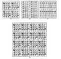
- FIG. 13a It is the block diagram which showed the structure of the encoding apparatus to which this invention is applied. It is the figure which showed the example of the scanning system for rearranging the conversion factor of the subblock arranged in two dimensions to one dimension. It is the figure which showed the example by which the scanning which made object a subblock is repeated recursively within a block. It is a functional block diagram of a forward scanning unit (13a). It is the flowchart which showed the 1st selection procedure of the forward scanning system in a forward scanning unit (13a). It is the figure which showed the relationship between the forward scanning system selected by a 1st selection procedure, the size of an encoding block, and an aspect ratio.
- FIG. 1 is a block diagram showing a configuration of a main part of an encoding apparatus to which the present invention is applied.
- a frame image is divided into encoded blocks serving as encoding units and inputted.
- Note that a device that encodes a moving image has an intra prediction (intraframe prediction) function and an inter prediction (interframe prediction) function, but the inter prediction function is not shown in the description of the present invention and is not shown. .
- Such an encoding apparatus may be configured by mounting an application (program) for realizing each function described later on a general-purpose computer, or a dedicated machine in which a part of the application is implemented in hardware or ROM. Alternatively, it may be configured as a single-function machine.
- the CPU 1 controls the entire apparatus including the encoding unit 6.
- the ROM 2 stores a basic program and various basic devices in a nonvolatile manner.
- the RAM 3 provides a work area for the CPU 1.
- the input / output unit 4 manages data input / output with an external device or an operator.
- the disk medium 5 stores input images and encoded data.
- the subtractor 10 calculates a difference (prediction residual signal) between the input image signal and the prediction signal output from the intra prediction prediction unit 16 for each block.
- the blocks are divided according to a quadtree structure or a quadtree binary structure.
- the prediction residual signal is input to the conversion unit 11.
- the transform unit 11 transforms the prediction residual signal from the time domain to the frequency domain and outputs a transform coefficient.
- the quantization unit 12 quantizes the transform coefficient according to a separately provided quantization parameter and outputs the level value.
- the forward scanning unit 13 a scans and rearranges the level values arranged two-dimensionally in the block, based on the block size and the prediction mode of the block received from the prediction unit 16. Specify the scanning method.
- the level values quantized and arranged two-dimensionally are rearranged one-dimensionally by the specified scanning method to form syntax elements.
- the syntax element is output after entropy coding.
- the n ⁇ m pixel conversion block is divided into 4 ⁇ 4 pixel sub-blocks, and is scanned diagonally (D: diagonal) in units of sub-blocks. ], Horizontal scanning (H: horizontal) [FIG. (B)] or vertical scanning (V: vertical) [(c)].
- the size of the sub-block is 4 ⁇ 4 pixels, and three scanning methods are listed as diagonal scanning, horizontal scanning, and vertical scanning, but the sub-block size, aspect ratio, or The scanning method candidates are not limited to these.
- the scanning method specified in the sub-block scanning method (the scanning method of the level value in the sub-block) is used recursively for the block scanning method (the scanning method of the sub-block itself).
- the block scanning method and the sub-block scanning method are not limited to the same method, and the block scanning method and the sub-block scanning method are specified independently (independently of each other). Also good.
- FIGS. 3A, 3B, and 3C show application examples of oblique scanning, horizontal scanning, and vertical scanning to an 8 ⁇ 8 pixel conversion block, respectively, and FIG. An example of applying oblique scanning to a pixel conversion block is shown.
- the inverse transform / inverse quantization unit 14 performs processing reverse to that of the transform unit 11 and the quantization unit 12, and generates a transform coefficient by dequantizing the level value output from the quantization unit 12.
- a prediction residual signal is generated by inverse orthogonal transform of the transform coefficient.
- the adder 15 adds the prediction residual signal output from the inverse quantization / inverse transform unit 14 and the prediction signal output from the prediction unit 16 to generate a reconstructed pixel signal.
- the reconstructed pixel signal is stored in the image memory 17 and then sent to the prediction unit 16.
- the prediction unit 16 outputs the result of intra prediction to the subtracter 10.
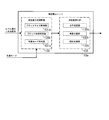
- FIG. 4 is a functional block diagram showing a configuration of a main part of the forward scanning unit 13a mounted on the entropy encoding unit 13.
- the forward scanning method selection unit 131 includes a block size determination unit 131a that determines the size of the conversion block, a block shape determination unit 131b that determines the aspect ratio of the conversion block, and a prediction mode determination 131c that determines the prediction mode received from the prediction unit 16.
- the scanning method for forward scanning each block is specified as one of oblique scanning, horizontal scanning, and vertical scanning.
- the forward scanning execution unit 132 includes a horizontal scanning unit 132a that scans two-dimensionally arranged level values in the horizontal direction (H scanning), a vertical scanning unit 132b that scans in the vertical direction (V scanning), and an oblique scanning (D And an oblique scanning unit 132c that performs scanning.
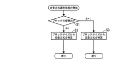
- FIG. 5 is a flowchart showing a first specific procedure of the forward scanning method in the forward scanning unit 13a
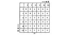
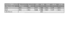
- FIG. 6 shows the forward scanning method specified by the first specific procedure, the block size and the aspect ratio.
- FIG. 6 (a) shows an example of the relationship between the block size and the scanning method when the horizontal scanning (H) is selected in step S2. If the block size is less than 16 ⁇ 16, the horizontal scanning ( If the block size is 16 ⁇ 16 or more, it is specified for oblique scanning (D). In this case, in step S3, the oblique scanning (D) is specified for all block sizes.
- FIG. 6B shows an example of the relationship between the block size and the scanning method when the vertical scanning (V) is selected in step S2, and if the block size is less than 16 ⁇ 16, the vertical scanning ( V), and if the block size is 16 ⁇ 16 or more, it is specified for oblique scanning (D). In this case, in step S3, the oblique scanning (D) is specified for all block sizes.
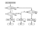
- FIG. 7 is a flowchart showing a second selection procedure of the forward scanning method in the forward scanning unit 13a.
- FIG. 8 shows the relationship between the forward scanning method selected in this embodiment, the block size and the aspect ratio.
- step S12 the block size is referred to, and if it is 4 ⁇ 4 or 8 ⁇ 8, the process proceeds to step S13, and the prediction mode-dependent (M) scanning method is selected.
- the block size is 16 ⁇ 16 or more, the process proceeds to step S14, and the diagonal scan (D) is selected.
- step S11 determines that the aspect ratio R of the block is other than 1, the process proceeds to step S15.
- step S15 the block size is referred to, and if it is 4 ⁇ 4 or 8 ⁇ 8, the process proceeds to step S16, and the prediction mode-dependent (M) scanning method is selected.
- the block size is 16 ⁇ 16 or larger, the process proceeds to step S17, and the oblique scanning (D) is selected.
- the block aspect ratio R is other than 1
- the prediction mode-dependent (M) scanning method is selected, and 16 If it is ⁇ 16 or more, the oblique scanning method (D) is selected.
- FIG. 9 shows a prediction mode-dependent scanning employed in H.265
- HEVC In H.265
- the present embodiment only describes the use of a specific means similar to H.265
- the size is not limited to the same value as H.265
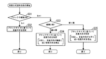
- FIG. 11 is a flowchart showing a third specific procedure of the forward scanning method in the forward scanning unit 13a.
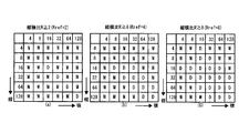
- FIG. 12 shows the relationship between the forward scanning method specified in the present embodiment, the block size, and the aspect ratio.
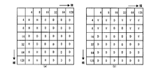
- the scanning method is determined based on the block size. In this embodiment, when the block size is 4 ⁇ 4 or 8 ⁇ 8, the horizontal scanning (H) [FIG. 12 (a)] or the vertical scanning method (V) [FIG. 12 (b)] is determined.
- the process proceeds to step S33 and the aspect ratio of the block is compared. If vertical ⁇ horizontal, the process proceeds to step S34, and the scanning method is determined based on the block size.
- the scanning method is specified as a scanning method other than the scanning method in which the scanning direction is relatively close to vertical. That is, the use of a scanning method in which the scanning direction is nearly vertical is prohibited.
- the process proceeds to step S35, and the scanning method is determined based on the block size.
- the scanning direction is specified as a scanning method other than the scanning method close to horizontal. That is, the use of a scanning method in which the scanning direction is almost horizontal is prohibited. Such restrictions on the scanning method are effective in avoiding the problem that the scanning order of the sub-blocks near the DC component in the block having a large aspect ratio is very different depending on the specified scanning method.
- the scanning order of the sub-blocks near the DC component is very far away.
- the scanning order of sub-blocks near the DC component is very far away.
- the vertical block size is compared with the horizontal block size.
- vertical scanning is performed.
- the use of (V) is prohibited, and when horizontal ⁇ vertical, the use of horizontal scanning (H) is prohibited, and a scanning method other than the prohibited scanning is specified.
- FIG. 13 is a flowchart showing a fourth specific procedure of the forward scanning method in the forward scanning unit 13a.
- FIG. 14 shows the relationship between the forward scanning method selected in this embodiment, the block size, and the aspect ratio R.
- step S42 the block size is referred to, and if it is 4 ⁇ 4 or 8 ⁇ 8, the process proceeds to step S43, and the scanning method (M) depending on the prediction mode adopted by the prediction unit 16 is specified.
- the scanning method (M) depending on the prediction mode adopted by the prediction unit 16 is specified.
- step S44 the process proceeds to step S44 and is specified as diagonal scanning (D).
- step S41 the aspect ratio R of the block is referred to, and if R ⁇ 1, the process proceeds to step S45, where it is determined whether or not the aspect ratio R of the block is equal to or greater than a predetermined threshold value Rref. If R ⁇ Rref, the process proceeds to step S46, and scanning (M) depending on the prediction mode is specified. On the other hand, if R ⁇ Rref, the process proceeds to step S47 to specify the oblique scanning (D).
- the aspect ratio R ⁇ 4 specifies the prediction mode-dependent scanning method (M), and otherwise, the oblique scanning (D ).
- FIG. 15 is a flowchart showing a fifth specific procedure of the forward scanning method in the forward scanning unit 13a.
- FIG. 16 shows the relationship between the forward scanning method selected in this embodiment, the block size and the aspect ratio.
- the block size is referred to, and if it is 4 ⁇ 4 or 8 ⁇ 8, the process proceeds to step S53, and the scanning method (M) depending on the prediction mode adopted by the prediction unit 16 is specified.
- the process proceeds to step S54 and is specified as the oblique scan (D).
- step S51 the aspect ratio of the block is referred to, and if R ⁇ 1, it proceeds to step S55 and the short side length S of the block is compared with a predetermined threshold value Sref. If the short side length S is equal to or greater than the threshold value Sref, the process proceeds to step S56, and the scanning mode (M) depending on the prediction mode is specified. If the short side length S is less than the threshold value Sref, the process proceeds to step S54 and is specified as oblique scanning (D).
- Sref 8
- the oblique scanning is performed regardless of the aspect ratio.
- D is specifically selected, and when S is “8” or more, it is specified as prediction mode-dependent scanning (M).
- S prediction mode-dependent scanning
- M prediction mode-dependent scanning
- the application range of the prediction mode dependent scanning (M) can be adjusted by the short side block length S and the predetermined threshold value Sref.
- FIG. 17 is a block diagram showing a configuration of a main part of a decoding apparatus to which the present invention is applied, and the same reference numerals as those described above represent the same or equivalent parts.
- the decoding apparatus according to the present invention acquires encoded data including a level value from the encoding apparatus 6 and decodes it to generate a decoded image.
- Such a decoding device may be configured by mounting an application (program) for realizing each function described later on a general-purpose computer, or a dedicated machine in which a part of the application is implemented in hardware or ROM. You may comprise as a single-function machine. Moreover, you may comprise integrally with the said encoding apparatus.
- the entropy decoding unit 23 includes an inverse scanning unit 23 a, and the syntax element obtained by entropy decoding the encoded bitstream is converted by the inverse scanning unit 23 a into a block size as a decoding unit, The level value of the two-dimensional array is converted by reverse scanning in the order according to the aspect ratio and the prediction mode.
- the inverse quantization unit 22 inversely quantizes the two-dimensionally arranged level values based on a separately provided inverse quantization parameter to restore a transform coefficient.
- the inverse transform unit 21 performs the inverse transform on the transform coefficient, thereby transforming the transform coefficient from the frequency domain to the time domain and restoring the prediction error signal.
- the prediction unit 24 calculates a prediction residual signal by applying a predetermined prediction mode to the restored and two-dimensionally arranged level values based on separately provided decoding parameters.
- the adder 20 adds the output of the inverse transformer 21 and the output of the predictor 24 to generate a decoded image signal. This decoded image signal is stored in the image memory 25 and used for intra prediction.
- FIG. 18 is a functional block diagram showing the configuration of the main part of the reverse scanning unit 23a implemented in the entropy decoding unit 23.
- the reverse scanning method selection unit 231 is based on the encoded data based on the encoded data, the block size determining unit 231a for determining the size of the block to be reconfigured, the block shape determining unit 231b for determining the vertical and horizontal size of the transform block, and the prediction mode employed at the time of encoding. And a prediction mode discrimination 231c for discriminating, and in accordance with each discrimination result, a reverse scanning method for rearranging sub-blocks by rearranging the quantized transform coefficients of the one-dimensional array into a two-dimensional array is performed by oblique scanning, horizontal Specify either scan or vertical scan.
- the reverse scanning execution unit 232 performs a horizontal scanning unit 232a that performs reverse horizontal scanning for rearranging the conversion coefficients arranged from the two-dimensional array to the one-dimensional array by the horizontal scanning (H), and the vertical scanning ( V) a vertical scanning unit 232b that performs reverse vertical scanning for rearranging the transform coefficients arranged in the one-dimensional array to the original two-dimensional array, and the transform coefficients arranged in the one-dimensional array by the oblique scanning (D) An oblique scanning unit 232c that performs reverse oblique scanning (ID scanning) for rearranging the two-dimensional array.
- a horizontal scanning unit 232a that performs reverse horizontal scanning for rearranging the conversion coefficients arranged from the two-dimensional array to the one-dimensional array by the horizontal scanning (H), and the vertical scanning ( V) a vertical scanning unit 232b that performs reverse vertical scanning for rearranging the transform coefficients arranged in the one-dimensional array to the original two-dimensional array, and the transform coefficients arranged in the one-
- the specific procedure of the reverse scanning method by the reverse scanning unit 23a is the same as the selection procedure of the scanning method at the time of encoding. Taking the first selection procedure described with reference to FIGS. When the aspect ratio R ⁇ 1 of the reconstructed block, diagonal scanning (D) or other is similarly selected based on the block size.
- the relative selection is performed based on the comparison result of the vertical and horizontal block lengths.
- the scanning direction is specified other than the scanning method close to vertical or the scanning method close to horizontal.
- the prediction mode dependence (M) is determined based on the aspect ratio.
- diagonal scan (D) is specified similarly.
- the prediction mode depends on the short side block length ( M) or diagonal scan (D) is specified as well.
- the present invention has been described by taking the application to an encoding device and a decoding device as examples.
- the present invention is not limited to this, and each of the encoding device and the decoding device is described.
- the present invention can be similarly applied to an encoding / decoding system having a function.
- Prediction 131 a forward scanning method selection unit, 131a, 231a, a block size determination unit, 131b, 231b, a block shape determination unit, 131c, 231c, a prediction mode determination, 132, a forward scanning execution unit, 132a, 232a, ... H (IH ) Scanning unit, 132b, 232b ... V (IV) scanning unit, 132c, 232c ... D (ID) scanning unit, 231 ... Reverse scanning method selection unit, 232 ... Reverse scanning execution unit
Landscapes
- Engineering & Computer Science (AREA)
- Multimedia (AREA)
- Signal Processing (AREA)
- Compression Or Coding Systems Of Tv Signals (AREA)
Abstract
Selon la présente invention, à l'étape S11, il est fait référence à un rapport d'aspect R d'un bloc, et lorsque R = 1, le processus passe à l'étape S12. À l'étape S12, lorsqu'une taille de bloc est déterminée comme 4x4 ou 8x8, le processus passe à l'étape S13 et un mode de balayage dépendant du mode de prédiction (M) est spécifié. Lorsque la taille du bloc est de 16x16 ou plus, le processus passe à l'étape S14 et un mode de balayage oblique (D) est spécifié. À l'étape S11, lorsque le rapport d'aspect R n'est pas 1, le processus passe à l'étape S15. À l'étape S15, lorsque la taille de bloc est déterminée comme 4x4 ou 8x8, le processus passe à l'étape S16, et le mode de balayage dépendant du mode de prédiction (M) est spécifié. Lorsque la taille du bloc est de 16x16 ou plus, le processus passe à l'étape S17 et le mode de balayage oblique (D) est spécifié.
Applications Claiming Priority (2)
| Application Number | Priority Date | Filing Date | Title |
|---|---|---|---|
| JP2018-049549 | 2018-03-16 | ||
| JP2018049549A JP6982525B2 (ja) | 2018-03-16 | 2018-03-16 | 動画像の符号化装置および方法、復号装置および方法ならびに符号化復号システム |
Publications (1)
| Publication Number | Publication Date |
|---|---|
| WO2019176207A1 true WO2019176207A1 (fr) | 2019-09-19 |
Family
ID=67906667
Family Applications (1)
| Application Number | Title | Priority Date | Filing Date |
|---|---|---|---|
| PCT/JP2018/046411 Ceased WO2019176207A1 (fr) | 2018-03-16 | 2018-12-17 | Dispositif et procédé de codage d'image mobile, dispositif et procédé de décodage, et système de codage/décodage |
Country Status (2)
| Country | Link |
|---|---|
| JP (1) | JP6982525B2 (fr) |
| WO (1) | WO2019176207A1 (fr) |
Citations (4)
| Publication number | Priority date | Publication date | Assignee | Title |
|---|---|---|---|---|
| JP2013192118A (ja) * | 2012-03-14 | 2013-09-26 | Sharp Corp | 算術復号装置、画像復号装置、算術符号化装置、および画像符号化装置 |
| JP2014158076A (ja) * | 2013-02-14 | 2014-08-28 | Kddi Corp | 走査順生成装置、動画像符号化装置、動画像復号装置、走査順生成方法、およびプログラム |
| WO2017195667A1 (fr) * | 2016-05-13 | 2017-11-16 | ソニー株式会社 | Dispositif et procédé de traitement d'image |
| JP2018042263A (ja) * | 2012-04-26 | 2018-03-15 | ソニー株式会社 | データ符号化及び復号化 |
Family Cites Families (1)
| Publication number | Priority date | Publication date | Assignee | Title |
|---|---|---|---|---|
| US9392301B2 (en) * | 2011-07-01 | 2016-07-12 | Qualcomm Incorporated | Context adaptive entropy coding for non-square blocks in video coding |
-
2018
- 2018-03-16 JP JP2018049549A patent/JP6982525B2/ja active Active
- 2018-12-17 WO PCT/JP2018/046411 patent/WO2019176207A1/fr not_active Ceased
Patent Citations (4)
| Publication number | Priority date | Publication date | Assignee | Title |
|---|---|---|---|---|
| JP2013192118A (ja) * | 2012-03-14 | 2013-09-26 | Sharp Corp | 算術復号装置、画像復号装置、算術符号化装置、および画像符号化装置 |
| JP2018042263A (ja) * | 2012-04-26 | 2018-03-15 | ソニー株式会社 | データ符号化及び復号化 |
| JP2014158076A (ja) * | 2013-02-14 | 2014-08-28 | Kddi Corp | 走査順生成装置、動画像符号化装置、動画像復号装置、走査順生成方法、およびプログラム |
| WO2017195667A1 (fr) * | 2016-05-13 | 2017-11-16 | ソニー株式会社 | Dispositif et procédé de traitement d'image |
Non-Patent Citations (5)
| Title |
|---|
| JIANLE CHEN ET AL.: "Algorithm Description of Joint Exploration Test Model 7 (JEM 7", JVET-G1001-VL, 21 July 2017 (2017-07-21), Retrieved from the Internet <URL:http://phenix.it-sudparis.eu/jvet/doc_end_user/documents/7_Torino/wg11/JVET-G1001-v1.zip> * |
| KEI KAWAMURA ET AL.: "Description of SDR video coding technology proposal by KDDI", JVET-J0016, 12 April 2018 (2018-04-12), pages i - iii, 1-22, Retrieved from the Internet <URL:http://phenix.it-sudparis.eu/jvet/doc_end_user/documents/10_San_Diego/wg11/JVET-J0016-v4.zip> * |
| WEI-YING KUNG ET AL.: "Entropy Coding for Non Square Blocks", JCTVC-H0511-R2, 2 February 2012 (2012-02-02), pages 1 - 4, Retrieved from the Internet <URL:http://phenix.it-sudparis.eu/jct/doc_end_user/documents/8_San_Jose/wg11/JCTVC-H0511-v3.zip> * |
| XIN ZHAO ET AL.: "Extended Mode-Dependent Coefficient Scanning", JCTVC-F124, 16 July 2011 (2011-07-16), pages 1 - 9, Retrieved from the Internet <URL:http://phenix.it-sudparis.eu/jct/doc_end_user/documents/6_Torino/wgll/JCTVC-F124-v2.zip> * |
| YOSHITAKA KIDANI: "CE7: Block size dependent coefficient scanning (CE7. 4.1", JVET-K0398-VL, 4 July 2018 (2018-07-04), pages 1 - 5, Retrieved from the Internet <URL:http://phenix.it-sudparis.eu/jvet/doc_end_user/documents/11_Ljubljana/wgll/JVET-K0398-v1.zip> * |
Also Published As
| Publication number | Publication date |
|---|---|
| JP2019161595A (ja) | 2019-09-19 |
| JP6982525B2 (ja) | 2021-12-17 |
Similar Documents
| Publication | Publication Date | Title |
|---|---|---|
| KR102820911B1 (ko) | 영상 정보 부호화 방법 및 복호화 방법 | |
| KR102583640B1 (ko) | 영상 부호화 방법 및 컴퓨터로 읽을 수 있는 기록 매체 | |
| JP6047614B2 (ja) | 映像復号化装置 | |
| JP5611498B1 (ja) | 映像復号化方法及び装置 | |
| JP2022087158A (ja) | イントラ予測方法とそれを利用した符号化器及び復号化器 | |
| JP5846676B2 (ja) | イントラ予測モード復号化方法及び装置 | |
| JP5989838B2 (ja) | 映像復号化装置 | |
| KR102333153B1 (ko) | 영상 정보 부호화 방법 및 복호화 방법 | |
| JP2014534748A (ja) | イントラ予測モードを誘導する方法及び装置 | |
| JPWO2012035746A1 (ja) | 映像符号化装置および映像復号装置 | |
| WO2019176207A1 (fr) | Dispositif et procédé de codage d'image mobile, dispositif et procédé de décodage, et système de codage/décodage | |
| KR20180000886A (ko) | 비디오 신호 처리 방법 및 장치 |
Legal Events
| Date | Code | Title | Description |
|---|---|---|---|
| 121 | Ep: the epo has been informed by wipo that ep was designated in this application |
Ref document number: 18909972 Country of ref document: EP Kind code of ref document: A1 |
|
| NENP | Non-entry into the national phase |
Ref country code: DE |
|
| 122 | Ep: pct application non-entry in european phase |
Ref document number: 18909972 Country of ref document: EP Kind code of ref document: A1 |