WO2019176208A1 - 建設機械 - Google Patents
建設機械 Download PDFInfo
- Publication number
- WO2019176208A1 WO2019176208A1 PCT/JP2018/046416 JP2018046416W WO2019176208A1 WO 2019176208 A1 WO2019176208 A1 WO 2019176208A1 JP 2018046416 W JP2018046416 W JP 2018046416W WO 2019176208 A1 WO2019176208 A1 WO 2019176208A1
- Authority
- WO
- WIPO (PCT)
- Prior art keywords
- point
- monitor
- work tool
- information
- image
- Prior art date
- Legal status (The legal status is an assumption and is not a legal conclusion. Google has not performed a legal analysis and makes no representation as to the accuracy of the status listed.)
- Ceased
Links
Images











Classifications
-
- E—FIXED CONSTRUCTIONS
- E02—HYDRAULIC ENGINEERING; FOUNDATIONS; SOIL SHIFTING
- E02F—DREDGING; SOIL-SHIFTING
- E02F9/00—Component parts of dredgers or soil-shifting machines, not restricted to one of the kinds covered by groups E02F3/00 - E02F7/00
- E02F9/26—Indicating devices
-
- E—FIXED CONSTRUCTIONS
- E02—HYDRAULIC ENGINEERING; FOUNDATIONS; SOIL SHIFTING
- E02F—DREDGING; SOIL-SHIFTING
- E02F3/00—Dredgers; Soil-shifting machines
- E02F3/04—Dredgers; Soil-shifting machines mechanically-driven
- E02F3/96—Dredgers; Soil-shifting machines mechanically-driven with arrangements for alternate or simultaneous use of different digging elements
- E02F3/963—Arrangements on backhoes for alternate use of different tools
-
- E—FIXED CONSTRUCTIONS
- E02—HYDRAULIC ENGINEERING; FOUNDATIONS; SOIL SHIFTING
- E02F—DREDGING; SOIL-SHIFTING
- E02F3/00—Dredgers; Soil-shifting machines
- E02F3/04—Dredgers; Soil-shifting machines mechanically-driven
- E02F3/28—Dredgers; Soil-shifting machines mechanically-driven with digging tools mounted on a dipper- or bucket-arm, i.e. there is either one arm or a pair of arms, e.g. dippers, buckets
- E02F3/36—Component parts
- E02F3/40—Dippers; Buckets ; Grab devices, e.g. manufacturing processes for buckets, form, geometry or material of buckets
-
- E—FIXED CONSTRUCTIONS
- E02—HYDRAULIC ENGINEERING; FOUNDATIONS; SOIL SHIFTING
- E02F—DREDGING; SOIL-SHIFTING
- E02F3/00—Dredgers; Soil-shifting machines
- E02F3/04—Dredgers; Soil-shifting machines mechanically-driven
- E02F3/96—Dredgers; Soil-shifting machines mechanically-driven with arrangements for alternate or simultaneous use of different digging elements
- E02F3/965—Dredgers; Soil-shifting machines mechanically-driven with arrangements for alternate or simultaneous use of different digging elements of metal-cutting or concrete-crushing implements
-
- E—FIXED CONSTRUCTIONS
- E02—HYDRAULIC ENGINEERING; FOUNDATIONS; SOIL SHIFTING
- E02F—DREDGING; SOIL-SHIFTING
- E02F3/00—Dredgers; Soil-shifting machines
- E02F3/04—Dredgers; Soil-shifting machines mechanically-driven
- E02F3/96—Dredgers; Soil-shifting machines mechanically-driven with arrangements for alternate or simultaneous use of different digging elements
- E02F3/966—Dredgers; Soil-shifting machines mechanically-driven with arrangements for alternate or simultaneous use of different digging elements of hammer-type tools
-
- E—FIXED CONSTRUCTIONS
- E02—HYDRAULIC ENGINEERING; FOUNDATIONS; SOIL SHIFTING
- E02F—DREDGING; SOIL-SHIFTING
- E02F9/00—Component parts of dredgers or soil-shifting machines, not restricted to one of the kinds covered by groups E02F3/00 - E02F7/00
- E02F9/26—Indicating devices
- E02F9/264—Sensors and their calibration for indicating the position of the work tool
Definitions
- the present invention relates to a construction machine such as a hydraulic excavator.
- a construction machine such as a hydraulic excavator performs construction such as excavation of a ground or the like to be worked by an operator operating an operation lever to drive a working machine including a bucket.
- Construction by construction machines is performed based on design drawings.
- design drawings In order to perform construction according to the design drawing, it is necessary to accurately grasp the positional relationship between the construction target surface and the work tool, but it is difficult for the operator to visually perform this.
- the technique which displays the positional relationship of the construction object surface seen from the side surface of the working machine and a work tool is proposed (for example, patent document 1).
- Patent Document 1 discloses a display system for a work machine having a work machine to which a bucket is attached, and drawing information for drawing an image in which the bucket is viewed from the side using information on the shape and dimensions of the bucket.
- the information includes the distance between the blade edge of the bucket and the bucket pin that attaches the bucket to the working machine, the angle between the straight line that connects the blade edge and the bucket pin, and the straight line that indicates the bottom surface of the bucket in a side view of the bucket ,
- the position of the cutting edge, the position of the bucket pin, and the front from the portion connecting the bucket to the working machine to the cutting edge Comprising at least one location outside of the bucket, the working machine of the display system is disclosed (paragraphs [0006]).
- work breakers for construction machinery include hydraulic breakers and rippers used for crushing work (work tools having a sharp tip shape) and small pieces used for dismantling work. Machines, grapples, etc. (work tools that have movable parts and perform crushing and gripping).
- the work machine display system described in Patent Document 1 does not support work tools other than buckets, it is not suitable for construction machines that are used for other than excavation work.
- the present invention has been made in view of the above problems, and an object of the present invention is to provide a construction machine that can display various work tools including a bucket on a display device without a sense of incongruity.
- the present invention is based on a working machine having a work tool rotatably attached via a first connection pin and a second connection pin, and drawing information and dimension information of the work tool.
- a display controller for creating a drawing graphic representing the side surface of the work tool and creating a target surface graphic representing the target surface based on the target surface information, and a display device for displaying the drawing graphic and the target surface graphic.
- the dimensional information of the work tool includes the first connection point located on the central axis of the first connection pin, the second connection point located on the central axis of the second connection pin, and the operation.
- Image information of a first drawing figure representing at least a part of the work implement including the robot, and the display controller calculates the posture of the work implement, and obtains the posture information of the work implement and the dimension information of the work implement.
- the first connection point in the first drawing figure Based on the coordinate values of the first connection point, the second connection point, and the first monitor point in the coordinate system on the image of the display device, the first connection point in the first drawing figure, A triangle whose vertex is the second connection point and the first monitor point is a triangle whose vertex is the first connection point, the second connection point, and the first monitor point in the coordinate system on the image of the display device.
- the first drawing figure is deformed so as to be congruent with the first drawing figure, and the first connected point in the first transformation drawing figure is created.
- the positions of the second connection point and the first monitor point coincide with the positions of the first connection point, the second connection point, and the first monitor point in the coordinate system on the image of the display device, respectively.
- the first deformed drawing figure is arranged on the screen of the display device.
- a triangle having apexes of the first connection point, the second connection point, and the first monitor point in the first drawing figure representing at least a part of the work tool is an image of the display device.
- a first modified drawing graphic is created so as to be congruent with a triangle having the first connection point, the second connection point, and the first monitor point as vertices in the upper coordinate system.
- the respective positions of the connection point, the second connection point, and the first monitor point coincide with the positions of the first connection point, the second connection point, and the first monitor point in the coordinate system on the image of the display device, respectively.
- the first deformed drawing figure is arranged on the screen of the display device.
- various work tools including buckets can be displayed on the display device without a sense of incongruity.
- FIG. 1 is a side view of a hydraulic excavator as an example of a construction machine according to an embodiment of the present invention. It is a block diagram which shows the structure of the vehicle body control system and display system which were mounted in the hydraulic shovel shown in FIG. It is a block diagram which shows the structure of the calculating part of the display controller shown in FIG. It is a flowchart which shows an example of the drawing calculation process of the display controller which concerns on 1st Example of this invention. It is a figure which shows the outline of the method of arrange
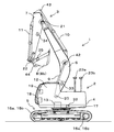
- FIG. 1 is a side view of a hydraulic excavator according to an embodiment of the present invention.
- the excavator 1 includes a lower traveling body 5, an upper turning body 4, and a work implement 3.
- the upper swing body 4 and the lower traveling body 5 constitute a vehicle body 2.
- the lower traveling body 5 has crawler belts 15a and 15b on both sides.
- the crawler belts 15a and 15b are driven by the travel motors 16a and 16b rotating by hydraulic pressure, and the excavator 1 travels.
- the upper turning body 4 is connected to the lower traveling body 5 via a turning wheel 17 so as to be rotatable, and is driven by being rotated hydraulically by a turning motor 13.
- the upper swing body 4 has a hydraulic control device 14 (shown in FIG. 2) that includes an operator cab 12, a swing motor 13, an engine (not shown), a hydraulic pump, a hydraulic control valve, and the like.
- a vehicle body operation device 18 and a display device 19 described later are installed in the cab 12.
- a vehicle body inclination angle sensor 32 that detects the inclination of the vehicle body is attached to the upper swing body 4.
- Antennas 23 a and 23 b are attached to the upper part of the upper swing body 4.
- the antennas 23a and 23b are used for receiving a signal from an artificial satellite (not shown) and detecting the current position of the excavator 1 on the earth.
- the work machine 3 includes a boom 6, an arm 7, a work tool 8 (a bucket 8 b in the example illustrated in FIG. 1), a first cylinder 9, a second cylinder 10, and a third cylinder 11.
- the boom 6 is rotatably attached to the upper swing body 4 via a first link pin 20.
- the arm 7 is rotatably attached to the tip end portion of the boom 6 via a second link pin 21.
- the work tool 8 is rotatably attached to the distal end portion of the arm 7 via a third link pin (first connection pin) 22.
- the first cylinder 9 is rotatably attached to the boom 6 via a first cylinder pin 42
- the second cylinder 10 is rotatably attached to the arm 7 via a second cylinder pin 43
- the third cylinder 11 is rotatably attached to the work tool 8 via a third cylinder pin (second connecting pin) 44.
- the first cylinder 9 drives the boom 6,
- the second cylinder 10 drives the arm 7,
- the third cylinder 11 drives the work tool 8 by expanding and contracting by hydraulic pressure.
- the boom 6, the arm 7, and the work tool 8 are attached with first to third rotation angle sensors 33-35 that detect the respective postures.
- FIG. 2 is a block diagram showing the configuration of the vehicle body control system 24 and the display system 25 mounted on the excavator 1.
- the vehicle body control system 24 includes a first cylinder 9, a second cylinder 10, a third cylinder 11, a turning motor 13, travel motors 16a and 16b, a hydraulic control device 14, a vehicle body.
- An operating device 18 and a vehicle body controller 26 are included.
- the hydraulic control device 14 distributes and supplies the hydraulic oil discharged from the hydraulic pump to a plurality of hydraulic actuators including the first cylinder 9, the second cylinder 10, the third cylinder 11, the turning motor 13, and the traveling motors 16a and 16b. Drive these.
- the vehicle body operation device 18 includes an operation member 27 and an operation amount detection unit 28.
- the operation member 27 is a member (for example, work) for an operator who enters the cab 12 to instruct the driving of the first cylinder 9, the second cylinder 10, the third cylinder 11, the turning motor 13, and the traveling motors 16a and 16b. Lever).
- the operation amount detector 28 detects the operation amount of the operation member 27 and sends a detection signal to the vehicle body controller 26.
- the vehicle body controller 26 includes an input / output unit 29 such as an A / D converter, a D / A converter and a digital input / output device, and an arithmetic unit 30 such as a CPU.
- an input / output unit 29 such as an A / D converter, a D / A converter and a digital input / output device
- an arithmetic unit 30 such as a CPU.
- the input / output unit 29 of the vehicle body controller 26 sends signals input from the vehicle body operating device 18 and the hydraulic control device 14 to the calculation unit 30 and sends the calculation results of the calculation unit 30 to the hydraulic control device 14.
- the calculation unit 30 of the vehicle body controller 26 calculates a command value to the hydraulic control device 14 based on the operation amount sent by the operation amount detection unit 28 and the state amount of the hydraulic control device 14.
- the display system 25 includes a vehicle body tilt angle sensor 32, a first to third rotation angle sensor 33-35, a correction information receiver 36, antennas 23a and 23b, a display device 19, and a display controller 31.
- the vehicle body inclination angle sensor 32 is, for example, an inertial measurement device (IMU), and is generally a sensor that combines an angular velocity sensor and an acceleration sensor.
- the vehicle body inclination angle sensor 32 is attached to the upper swing body 4 and has a horizontal direction in the operation plane of the work implement 3. This is used to detect the angle between the front and rear direction of the upper swing body 4 and the vertical (gravity) direction in the left-right direction when the left-right direction is perpendicular to the operation plane of the work implement 3.
- the 1-3 rotation angle sensor 33-35 is, for example, an IMU, and is attached to the boom 6, the arm 7, and the work tool 8, respectively, and the boom 6, the arm 7, and the work tool around the 1-3 link pin 20-22. 8 is detected, and the angle of the boom 6 with respect to the upper swing body 4, the angle of the arm 7 with respect to the boom 6, and the angle of the work tool 8 with respect to the arm 7 are output.
- the correction information receiver 36 is, for example, a wireless communication device, and receives correction information that is transmitted by radio from a correction information transmitter (not shown) outside the excavator 1 and used for calculation of the global position. .
- the display device 19 includes an operation unit 37 and a display unit 38.
- the operation unit 37 of the display device 19 is, for example, a switch, which is operated by an operator to switch display information, coordinate information of a target surface stored in a storage unit 41 of the display controller 31 described later, the type of the work tool 8, Add or change drawing information settings such as dimensions.
- the display unit 38 of the display device 19 is, for example, a liquid crystal display or a speaker, and displays drawing information calculated by the calculation unit 40 of the display controller 31 so that the worker can confirm the work content.
- the display device 19 may be one in which the operation unit 37 and the display unit 38 are integrated, such as a touch panel.
- the display controller 31 includes an input / output unit 39 such as an A / D converter, a D / A converter, and a digital input / output device, a calculation unit 40 such as a CPU, and a storage unit 41 such as a ROM and a RAM.
- an input / output unit 39 such as an A / D converter, a D / A converter, and a digital input / output device
- a calculation unit 40 such as a CPU
- a storage unit 41 such as a ROM and a RAM.
- the input / output unit 39 of the display controller 31 is input from the angle signal input from the vehicle body inclination angle sensor 32 and the first to third rotation angle sensor 33-35, the detection signals of the antennas 23a and 23b, and the operation unit 37 of the display device 19.
- the operation signal thus sent is sent to the calculation unit 40, and the calculation result of the calculation unit 40 is sent to the display unit 38 of the display device 19.
- the input / output unit 39 of the display controller 31 further includes an external connection terminal (for example, a USB terminal) that can be connected to an external storage device (for example, a USB (Universal Serial Bus) memory) 90, and is stored in the external storage device 90. It is possible to save target surface information and work tool drawing information edited by other electronic devices in the storage unit 41.
- an external connection terminal for example, a USB terminal
- an external storage device for example, a USB (Universal Serial Bus) memory
- the display controller 31 includes the storage unit 41 that stores drawing information and dimension information of the work tool 8 and the input / output unit 39 that can be connected to the external storage device 90.
- the drawing information and dimensional information of the work tool 8 stored in 90 can be stored in the storage unit 41 via the input / output unit 39.
- FIG. 3 is a block diagram illustrating a configuration of the calculation unit 40 of the display controller 31.
- the calculation unit 40 of the display controller 31 includes a global position calculation unit 40a, a posture calculation unit 40b, a work tool position calculation unit 40c, and a drawing calculation unit 40d.
- the storage unit 41 of the display controller 31 stores vehicle body dimension parameters, angle conversion parameters, target surface information, and work tool drawing information.
- vehicle body dimension parameters include, for example, the dimensions of the boom 6, the arm 7, and the work tool 8, and the relative position (such as a three-dimensional vector) between the antennas 23 a and 23 b and the first link pin 20.
- target surface information includes the coordinates of the cross section in at least one plane that the hydraulic excavator 1 is to work on.
- the work tool drawing information includes image information of a drawing figure of the work tool 8 and coordinate values on the image associated with the drawing figure.
- the global position calculation unit 40a is an RTK-GNSS (RealTime Kinetic-Global Navigation Satellite System, GNSS is a global navigation satellite. System) is used to calculate the current position of the antennas 23a and 23b in the global (earth) coordinate system.
- RTK-GNSS RealTime Kinetic-Global Navigation Satellite System
- the posture calculation unit 40b is configured to incline the left and right tilt of the upper swing body 4 based on the detection signal of the vehicle body tilt angle sensor 32, the angle signal of the first to third rotation angle sensors 33-35, and the angle conversion parameter of the storage unit 41.
- An angle ⁇ 3 around the third link pin 22 with respect to is calculated.
- the work tool position calculation unit 40c is based on the angle ⁇ 1- ⁇ 3, which is the calculation result of the posture calculation unit 40b, and the vehicle body dimension parameter of the storage unit 41, and is based on the center of the first link pin 20 as the origin.
- the Z axis passes through the origin and the center of the second and third link pins 21 and 22 and the upward direction of gravity is positive, and the X axis is perpendicular to the Z axis and the extension direction of the work implement 3 is positive.
- a machine operation plane (XZ plane) is defined, and the coordinates of the first monitor point MP1 that is a point of interest on the work in the work tool 8 on the work machine operation plane (XZ plane) and the central axis of the third link pin 22 And the coordinate of the central axis of the third cylinder pin 44 are calculated.
- the work tool position calculation unit 40c further includes a global (earth) coordinate system based on the angles ⁇ 0x and ⁇ 0y which are calculation results of the posture calculation unit 40b, the calculation results of the global position calculation unit 40a, and the vehicle body dimension parameters of the storage unit 41.
- the first monitor point MP1, the center axis coordinate of the third link pin 22, and the center axis coordinate of the third cylinder pin 44 are calculated.
- the drawing calculation unit 40d is information on the type and size of the work tool 8 set by the operation unit 37 of the display device 19, the calculation result of the work tool position calculation unit 40c, the target surface information in the storage unit 41, and the work tool drawing. Based on the information, a guidance image is created and output to the display unit 38.
- a hydraulic excavator 1 according to a first embodiment of the present invention will be described with reference to FIGS.
- the excavator 1 according to this embodiment includes a hydraulic breaker as the work tool 8.
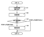
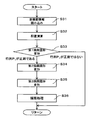
- FIG. 4 is a flowchart illustrating an example of the drawing calculation process of the display controller 31 according to the present embodiment.
- the display controller 31 is configured so that the target surface and the work tool 8 are in a positional relationship according to the flowchart shown in FIG. A side image (guidance image) showing is created.
- step S1 target surface information is read from the storage unit 41, and a target surface graphic 48 (shown in FIG. 5A) is created.
- the target surface information is, for example, polygon data composed of line segments and planes arranged in the global coordinate system.
- the target plane graphic 48 is an intersection line between the work machine operation plane (XZ plane) and the plane constituting the polygon data, and is defined in the local coordinate system of the work machine operation plane (XZ plane).
- the work machine operation plane (XZ plane) is the position of the first to third link pins 20-22 relative to the antennas 23a and 23b obtained by the global position calculation unit 40a and the antennas 23a and 23b included in the vehicle body dimension parameter of the storage unit 41.
- the target surface graphic 48 is sequentially updated when the excavator 1 moves or rotates with respect to the target surface information by a traveling operation or a turning operation.
- step S2 the target surface graphic 48 obtained from step S1 and the work tool position obtained from the work tool position calculation unit 40c are used to place them in the coordinate system on the image.
- the maximum value [pxmax, pymax] in the vertical direction and the horizontal direction is defined by the size of the screen of the display unit 38, and therefore, at least one of the entire work tool 8 and the target surface graphic 48 is formed.
- the scale Ksc and the offset OP1 are determined in order to arrange to include two line segments.
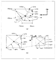
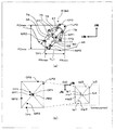
- FIG. 5 shows a drawing figure and a target of the hydraulic breaker 8a based on the positions of the first monitor point MP1, the third link pin 22, the third cylinder pin 44, and the target surface figure 48 on the work machine operation plane (XZ plane).
- positioning the surface figure 48 to the coordinate system on an image is shown.
- a point located at the tip of the hydraulic breaker 8a (a point located on the contour of the hydraulic breaker 8a projected on the work machine operation plane (XZ plane)) is defined as a first monitor point MP1
- a point where the central axis of the third link pin 22 intersects the actuator operating plane (XZ plane) (hereinafter referred to as “third link pin central point” as appropriate) is defined as a point LP3, and the central axis of the third cylinder pin 44 is formed.
- a point that intersects the motivation operation plane (XZ plane) (hereinafter referred to as “third cylinder pin center point” as appropriate) is defined as a point CP3.
- the distances between all the line segments constituting the target surface graphic 48 and the point MP1 are calculated, and the closest line segment of the target surface graphic 48 is the nearest line.
- the first nearest target surface point TP1 included in the nearest neighbor line segment is acquired.
- the offset OP1 is calculated by the following expression so that the center of the acquired maximum and minimum values of the four points is the origin.
- the scale Ksc1 is obtained by dividing the maximum value [pxmax, pymax] of the screen size by the difference between the maximum value and the minimum value of the four points on the work machine operation plane (XZ plane).
- the scale Ksc1 is calculated by the following equation.
- Min in the expression is an operator for selecting the minimum value from the arguments, and “ ⁇ sc1” is a positive real number for displaying four points on the work machine operation plane (XZ plane) on the inner side from the screen end. Is the coefficient.
- the screen coordinate system generally has an x-axis with the upper left corner of the screen as the origin, a positive direction in the right direction, and a y-axis in which the lower direction is positive.
- XZ plane work machine operation plane
- a point MP1, a point LP3, a point CP3, and a point TP1 of the work tool position and the target plane graphic 48 on the work machine operation plane (XZ plane) are converted into a point mp1, a point lp3, Conversion to point cp3 and point tp1, respectively.
- step S3 the work tool type information set by the operation unit 37 of the display device 19 using the three points of points mp1, lp3, and cp3 indicating the position of the work tool in the coordinate system on the image calculated in step S2. Performs a process of deforming the drawing figure included in the work tool drawing information associated with the hydraulic breaker 8a.
- the work tool drawing information associated with the work tool type information being the hydraulic breaker 8a includes the first monitor point MP1, the third link pin center point (first connection point) LP3, and the third cylinder pin center of the hydraulic breaker 8a.
- Image information of the first drawing figure 49 (shown in FIG. 6A) including the point (second connection point) CP3, the first monitor point MP1 in the coordinate system on the first drawing figure 49, and the center of the third link pin It includes a point LP3, a point mp1a indicating the position of the third cylinder pin center point CP3, a point lp3a, and a coordinate value of the point cp3a.
- FIG. 6 shows an example of a method of deforming the first drawing figure 49 representing the hydraulic breaker 8a based on the working tool dimension information of the actually installed hydraulic breaker 8a and the working tool drawing information indicating the hydraulic breaker 8a. Yes.
- a linear mapping is used as a method for deforming the first drawing figure 49.
- the linear map is expressed by the following equation.
- the image deformation matrix A used for the linear mapping that deforms the first drawing figure 49 can be obtained from the work tool size information of the hydraulic breaker 8a and the coordinate information on the image plane.
- a vector v2 [v2x, v2y] connecting lp3a to the point mp1a is assumed.
- Matrices P1 and Q1 respectively created from the vectors u1 and u2 and the vectors v1 and v2 are expressed by the following equations.
- the vectors v1 and u1 and the vectors v2 and u2 are vectors corresponding to the hydraulic breaker 8a actually attached to the hydraulic excavator 1 as the work tool 8 and the hydraulic breaker 8a on the image, respectively. From 6), the method of converting from the matrix P1 to the matrix Q1 using the image deformation matrix A1 is expressed by the following equation.
- the image transformation matrix A1 is expressed by the following equation using the matrix Q1 and the inverse matrix P1 ⁇ 1 of the matrix P1.
- the inverse matrix P1 ⁇ 1 of the matrix P1 exists when the matrix P1 is regular. For example, as a determination when the matrix P1 is not regular, when the determinant of the matrix P1 is 0, step S4 The calculation of the drawing calculation unit 40d is terminated without proceeding to the next step.
- the first drawing figure 49 of the hydraulic breaker 8a is deformed by using the image deformation matrix A obtained by the equation (8).
- a first modified drawing figure 49a (shown in FIG. 6B) is created, and the process proceeds to step S4.
- step S4 the screen of the display unit 38 is obtained from the first deformed drawing figure 49a of the hydraulic breaker 8a obtained in step S3, and the arrangement of the work tool 8 and the target surface figure 48 on the drawing screen obtained from step S2. Create a drawing image.
- the first post-deformation drawing figure 49a of the hydraulic breaker 8a includes three points, a point mp1a, a point lp3a, and a point cp3a (shown in FIG. 6B) included in the image, corresponding work tools included in the drawing image. By aligning with the three points of the position point mp1, the point lp3, and the point cp3 (shown in FIG. 6A), they are arranged in the drawing image.
- the image of the target surface figure 48 passes through the point tp1 and extends a straight line having the same inclination as the nearest segment TL1 to both sides of the point tp1.
- Equation (3) is applied in order from the line segment included in the target surface graphic 48 and adjacent to the nearest line segment TL1, so that the target surface graphic 48 in the coordinate system on the image is within the range that fits on the screen. draw.
- the work machine 3 having the work tool 8 rotatably attached via the first connection pin 22 and the second connection pin 44, and the drawing information and the dimension information of the work tool 8 are used.
- a display controller 31 for creating a drawing graphic representing the side surface of the work tool 8 and for creating a target surface graphic representing the target surface based on the target surface information are provided with a display controller 31 for creating a drawing graphic representing the side surface of the work tool 8 and for creating a target surface graphic representing the target surface based on the target surface information, and a display device 19 for displaying the drawing graphic and the target surface graphic.
- the dimension information of the work tool 8 includes the first connection point LP3 located on the central axis of the first connection pin 22, the second connection point CP3 located on the central axis of the second connection pin 44, And the position information of the first monitor point MP1 located on the contour of the work tool 8 projected onto the operation plane of the work machine 3, and the drawing information of the work tool 8 includes the first connection point LP3, the second connection point CP3, and the like.
- the display controller 31 includes image information of the first drawing figure 49 representing at least a part of the work tool 8 including the first monitor point MP1, the posture calculation unit 40b for calculating the posture of the work implement 3, and the work implement 3 Based on the posture information and the dimensional information of the work tool 8, the work tool position that calculates the coordinate values of the first connection point LP3, the second connection point CP3, and the first monitor point MP1 in the coordinate system on the image of the display device 19.
- the first connecting point LP3 in the coordinate system on the image of the display device 19 is a triangle having the computing unit 40c and the first connecting point LP3, the second connecting point CP3, and the first monitor point MP1 in the first drawing figure 49 as vertices.
- the first drawing figure 49 is deformed so as to be congruent with the triangle having the second connection point CP3 and the first monitor point MP1 as vertices.
- the first post-deformation drawing figure 49a is created, and the positions of the first connection point LP3, the second connection point CP3, and the first monitor point MP1 in the first post-deformation drawing figure 49a are displayed on the image of the display device 19.
- a drawing operation unit that arranges the first deformed drawing figure 49a on the screen of the display device 19 so as to coincide with the positions of the first connection point LP3, the second connection point CP3, and the first monitor point MP1 in the coordinate system. 40d.
- the first connection point lp3a, the second connection point cp3a, and the first monitor point mp1a in the first drawing figure 49 representing the hydraulic breaker 8a are the apexes.
- the first post-deformation drawn figure 49a is congruent with the triangle having the first connection point lp3, the second connection point cp3, and the first monitor point mp1 as vertices in the coordinate system on the image of the display device 19.
- the first connection point lp3a, the second connection point cp3a, and the first monitor point mp1a that are created in the first deformed drawing figure 49a are the first connection point lp3 and the second connection point in the coordinate system on the image of the display device 19. Drawing after the first deformation so as to coincide with cp3 and the first monitor point mp1 Shape 49a is placed on the screen of the display device 19. As a result, the hydraulic breakers 8a having different dimensions and shapes can be displayed on the display device 19 without a sense of incongruity.
- the hydraulic breaker 8a is illustrated as the work tool 8.
- the work breaker 8 is not limited as long as the work tool 8 includes the first monitor point MP1, the third link pin 22, and the third cylinder pin 44. It may be replaced with a single claw ripper.
- a hydraulic excavator 1 according to a second embodiment of the present invention will be described with reference to FIGS.
- the hydraulic excavator 1 according to this embodiment includes a bucket as the work tool 8.
- the bucket 8b as the work tool 8 includes at least one monitor point different from the first monitor point MP1, and the work tool. 8 includes one structural feature point and 8 includes at least two drawing figures used for drawing the work tool 8.
- the work tool position calculation unit 40c (shown in FIG. 3) further includes second and third monitor points that are different from the first monitor point MP1 on the work in the work tool 8.
- MP2 and MP3 and the structural feature points of the work tool 8 (hereinafter referred to as “first feature points”) FP1 are calculated on the work machine operation plane (XZ plane) and the global coordinate system.
- the drawing calculation unit 40d (shown in FIG. 3) is similar to the first embodiment, and information on the type and size of the work tool set by the operation unit 37 of the display device 19 and the calculation of the work tool position calculation unit 40c.
- a guidance image is created based on the result and the target surface information and work implement drawing information in the storage unit 41, and is output to the display unit 38.
- FIG. 7 is a flowchart illustrating an example of the drawing calculation process of the display controller 31 according to the present embodiment.
- the display controller 31 is configured so that the target surface and the work tool 8 are in a positional relationship according to the flowchart shown in FIG. A side image (guidance image) showing is created.
- step S11 the target surface information is read from the storage unit 41 as in step S1 in the first embodiment.
- step S12 the target surface graphic 48 obtained from step S11 and the work tool position obtained from the work tool position calculation unit 40c are used to place them in the coordinate system on the image.
- the maximum value [pxmax, pymax] in the vertical direction and the horizontal direction is defined by the size of the screen of the display unit 38, and therefore, at least one of the entire work tool 8 and the target surface graphic 48 is formed.
- the scale Ksc1 and the offset OP1 are determined in order to arrange to include two line segments.
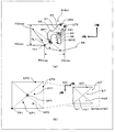
- FIG. 8 shows the first monitor point MP1, the second and third monitor points MP2, MP3, the first feature point FP1, the third link pin center point LP3, and the third cylinder pin center point on the work machine operation plane (XZ plane).
- An outline of a method of arranging the drawing figure of the bucket 8b and the target plane figure 48 in the coordinate system on the image based on the positions of the CP3 and the target plane figure 48 is shown.
- a point located at the tip of the bucket 8b (a point located on the outline of the bucket 8b projected onto the work machine operation plane (XZ plane)) is defined as a first monitor point MP1, and the bucket 8b
- the points (points located on the outline of the bucket 8b projected on the work machine operation plane (XZ plane)) are defined as second and third monitor points MP2 and MP3.
- it is located on the outline of the bucket 8b projected on the joint point (work machine operation plane (XZ plane)) of the member for attaching the bucket 8b to the arm 7 and the third cylinder 11 and the member to be the back plate of the bucket 8b.
- Point is defined as a first feature point FP1.
- the distances between all the line segments constituting the target surface graphic 48 and the point MP1 are calculated, and the closest line segment of the target surface graphic 48 is the nearest line.
- the first nearest target surface point TP1 included in the nearest neighbor line segment is acquired.
- the offset OP1 is calculated by the equation (1) so that the center of the acquired maximum value and minimum value of the seven points is the origin.
- the scale Ksc1 is obtained by dividing the maximum value [pxmax, pymax] of the screen size by the difference between the maximum value and the minimum value of the seven points on the work machine operation plane (XZ plane).
- the scale Ksc1 is calculated by the equation (2).
- a point MP1, a point MP2, a point MP3, a point FP1, a point LP3, a point CP3, and a point TP1 of the work tool position and the target plane figure 48 on the work machine operation plane (XZ plane) (local coordinate system) are expressed by the following equation (3).
- the point mp1, the point mp2, the point mp3, the point fp1, the point lp3, the point cp3, and the point tp1 in the coordinate system on the image are respectively converted.
- step S13 the work tool type information set by the operation unit 37 of the display device 19 using the three points of the point mp1, the point lp3, and the point cp3 indicating the position of the work tool in the coordinate system on the image calculated in step S12.
- the first drawing figure 53 included in the work tool drawing information associated with the bucket 8b is deformed.
- the work tool drawing information associated with the work tool type information being the bucket 8b is the first drawing figure including the first monitor point MP1, the third link pin center point LP3, and the third cylinder pin center point CP3 of the bucket 8b. 53, point mp1a, point lp3a, point cp3a indicating the positions of the first monitor point MP1, the third link pin center point LP3, and the third cylinder pin center point CP3 in the coordinate system on the first drawing figure 53 Coordinate value of
- FIG. 9 shows an example of a method for deforming the first drawing figure 53 of the bucket 8b based on the work tool dimension information of the bucket 8b actually attached and the work tool drawing information indicating the bucket 8b.
- a linear mapping is used as in the first embodiment.
- the linear map is expressed by Expression (4).
- the image deformation matrix A1 used for the linear mapping for converting the first drawing figure 53 can be obtained from the work tool size information of the bucket 8b and the position information at the coordinates of the first drawing figure 53.
- a vector u1 [u1x, u1y] connecting the point lp3 to the point cp3
- a vector u2 [u2x, u2y] connecting the point lp3 to the point mp1
- a vector v1 [v1x, v1y] and a point connecting the point lp3a to the point cp3a
- the image deformation matrix A1 is expressed by equations (5)-(8).
- the inverse matrix P1 ⁇ 1 of the matrix P1 exists when the matrix P1 is regular. For example, as a determination when the matrix P1 is not regular, if the determinant of the matrix P1 is 0, step S14 The calculation of the drawing calculation unit 40d is terminated without proceeding to the next step.
- the first drawing figure 53 of the bucket 8b is deformed by using the image deformation matrix A1 obtained by the equation (8) to obtain the first A deformed drawing figure 53a (shown in FIG. 9B or FIG. 10) is created, and the process proceeds to step S14.
- step S14 the same loop process as the number of monitor points different from the first monitor point MP1 is performed N times.
- N the number of monitor points different from the first monitor point MP1
- the point mp (k), the point mp (k + 1), the point fp1 indicating the position of the work tool in the coordinate system on the image calculated in step S12, that is, the number of loops k 1, mp1, point mp2, and point fp1 are 3 Using the points, a process of deforming the second drawing figure 54 included in the work tool drawing information associated with the work tool type information set by the operation unit 37 of the display device 19 being the bucket 8b is performed.
- the work tool drawing information associated with the work tool type information being the bucket 8b is a second drawing which is a triangle having the first monitor point MP1, the second monitor point MP2, and the first feature point FP1 of the bucket 8b as vertices.
- the triangle exists when all of the three points mp1b, mp2b, and fp1b constituting the triangle do not exist on the same straight line.
- the step is performed. Without proceeding to S15, the calculation of the drawing calculation unit 40d is terminated.
- step S15 When the three points do not exist on the same straight line, the second drawing graphic 54 is deformed so that the triangle connecting the points mp1, mp2, and fp1 and the triangle that is the second drawing graphic 54 are congruent. Thus, a second post-deformation drawing figure 54a (shown in FIG. 10) is created, and the process proceeds to step S15.
- the work tool drawing information associated with the work tool type information being the bucket 8b is a third drawing which is a triangle having the second monitor point MP2, the third monitor point MP3, and the first feature point FP1 of the bucket 8b as vertices.
- the image information of the graphic 55 and the coordinate values of the points mp2c, mp3c, and fp1c indicating the positions of the second monitor point MP2, the third monitor point MP3, and the first feature point FP1 in the coordinate system on the third drawing graphic 55 Including.
- the triangle exists when all of the three points mp2c, mp3c, and fp1c constituting the triangle do not exist on the same straight line.
- the step is performed. Without going to S15, the calculation of the drawing calculation unit 40d is terminated.
- the third drawing figure 55 is deformed so that the triangle connecting the points mp2, mp3, and fp1 and the triangle that is the third drawing figure 55 are congruent.
- the third post-deformation drawing figure 55a (shown in FIG. 10) is created, and the process proceeds to step S17.
- step S18 the first and third post-deformation drawing figures 53a-55a of the bucket 8b obtained in steps S13, S14, and S16, the arrangement of the work tool 8 and the target surface figure 48 on the drawing screen obtained from step S12, and Then, a drawing image is created on the screen of the display unit 38.
- FIG. 10 shows a state in which the first to third modified drawing figures 53a to 55a representing the bucket 8b are arranged in the drawing image.
- the first post-deformation drawing figure 53a of the bucket 8b includes three points, a point mp1a, a point lp3a, and a point cp3a included in the image, and a point mp1, a point lp3, and a point cp3 at the corresponding work tool positions included in the drawing image. By aligning them with the three points, they are arranged in the drawn image.
- the second post-deformation drawing figure 54a of the bucket 8b has three points of points mp1b, mp2b, and fp1b included in the image, and points mp1, mp2, and fp1 of the corresponding work tool positions included in the drawing image. By aligning them with the three points, they are arranged in the drawn image.
- the third post-deformation drawing figure 55a of the bucket 8b includes three points mp2c, mp3c, and fp1c included in the image, and points mp2, mp3, and fp1 of the corresponding work tool positions included in the drawing image. By aligning them with the three points, they are arranged in the drawn image.
- the image of the target surface figure 48 is drawn within the range that fits on the screen, as in the first embodiment.
- the work tool 8 is a bucket
- the first monitor point MP1 is located at the tip of the bucket 8
- the dimensional information of the work tool 8 is the first monitor point MP1 on the back of the bucket 8. It further includes position information of the second monitor point MP2 at the position and the first feature point FP1 at another position on the back of the bucket 8, and the drawing information of the work tool 8 includes the first monitor point MP1, the second monitor It further includes image information of a second drawing figure 54 representing a part of the work tool 8 including the point MP2 and the first feature point FP1, and the work tool position calculation unit 40c is based on the dimensional information of the work tool 8 and stores the second information.
- the coordinate values of the monitor point MP2 and the first feature point FP1 are calculated, and the drawing calculation unit 40d has the first monitor point MP1, the second monitor point MP2, and the first monitor point in the second drawing figure 54.
- the triangles having the vertex FP1 as the vertex are congruent with the triangles having the first monitor point MP1, the second monitor point MP2, and the first feature point FP1 as the vertex in the coordinate system on the image of the display device 19.
- the second drawn graphic 54 is deformed to create a second deformed drawn graphic 54a, and the positions of the first monitor point MP1, the second monitor point MP2, and the first feature point FP1 in the second drawn graphic 54 are displayed on the display device 19.
- the second post-deformation drawing figure 54a is arranged on the screen of the display device 19 so as to coincide with the positions of the first monitor point MP1, the second monitor point MP2 and the first feature point FP1 in the coordinate system on the image. To do.
- the dimensional information of the work tool 8 further includes position information of the second monitor point MP2, the first feature point FP1, and the third monitor point MP3 located on the back surface of the bucket 8, and the drawing information of the work tool 8 Further includes image information of a third drawing figure 55 representing a part of the work tool 8 including the second monitor point MP2, the third monitor point MP3, and the first feature point FP1, and the work tool position calculation unit 40c Based on the dimensional information of the tool 8, the coordinate value of the third monitor point MP3 is calculated, and the drawing calculation unit 40d performs the second monitor point MP2, the third monitor point MP3, and the first feature point FP1 in the third drawing figure 55.
- the third drawing figure 55 is deformed so as to be congruent with the shape to create a third post-deformation drawing figure 55a, and the second monitor point MP2, the third monitor point MP3, and the first monitor point in the third post-deformation drawing figure 55a
- the third post-deformation drawn graphic so that each position of the feature point FP1 matches each position of the second monitor point MP2, the third monitor point MP3, and the first feature point FP1 in the coordinate system on the image of the display device 19.
- 55 a is arranged on the screen of the display device 19.
- the bucket 8b having different dimensions and shapes can be displayed on the display device 19 without a sense of incongruity.
- the bucket 8b is illustrated as the work tool 8.
- the work tool 8 includes a plurality of monitor points, the third link pin 22, and the third cylinder pin 44. It may be replaced with.
- the number of monitor points is three, but the number of monitor points may be two or more, and the number is not limited.
- the second and third drawing figures 54 and 55 are deformed so that the triangles are congruent.
- a linear mapping may be used. .
- the deformation of the second and third drawing figures 54 and 55 is executed so that the triangles are congruent, so that the image of the bucket 8b to be drawn becomes angulated at the monitor point.
- step S18 by using a spline curve that passes through an arbitrary monitor point and a point including the first feature point FP1, the region between the spline curve and the second and third drawing figures 54 and 55 is filled, so that FIG. As shown by the bottom surface 56 (broken line portion) of the bucket 8b shown in FIG.
- a hydraulic excavator 1 according to a third embodiment of the present invention will be described with reference to FIGS.
- the excavator 1 according to the present embodiment includes a crusher as a work tool 8.
- the split crusher 8c as the work tool 8 includes a work tool frame (base part) 57 and a work tool arm (first driven part).
- the work tool frame 57 includes the first monitor point MP1
- the work tool arm 58 includes the second monitor point MP2
- the work tool frame 57 includes the second monitor point MP2.
- the first feature point FP1 is rotated around the first feature point FP1 and two drawing figures of the work tool 8 are included.
- the work tool arm 58 is rotatably connected to the work tool frame 57 via a fourth link pin (third connection pin) 59 and is driven by the fourth cylinder 63. That is, the first feature point FP1 is a point on the central axis of the fourth link pin 59.
- the work tool arm 58 is provided with a fourth rotation angle sensor 64 as a first posture detecting device for detecting the posture.
- the fourth rotation angle sensor 64 is, for example, an IMU, is attached to the work tool arm 58, detects an angle formed with the vertical (gravity) direction of the work tool arm 58 around the fourth link pin 59, and detects the angle with respect to the work tool frame 57. The angle of the work tool arm 58 is output.
- the posture calculation unit 40b (shown in FIG. 3) further includes a work tool for the work tool arm 58 based on the angle signal of the fourth rotation angle sensor 64 and the angle conversion parameter of the storage unit 41. An angle ⁇ 4 around the fourth link pin 59 with respect to the frame 57 is calculated.
- the work tool position calculation unit 40c (shown in FIG. 3) further includes a second monitor point MP2 included in the work tool arm 58 based on the angle ⁇ 4 calculated by the posture calculation unit 40b, and a work The position on the work machine operation plane (XZ plane) of the structural first feature point FP1 included in the tool frame 57 and the position in the global coordinate system are calculated.
- the drawing calculation unit 40d (shown in FIG. 3) is similar to the first embodiment, and information on the type and size of the work tool set by the operation unit 37 of the display device 19 and the calculation of the work tool position calculation unit 40c. A guidance image is created based on the result and the target surface information and work implement drawing information in the storage unit 41.
- FIG. 11 is a flowchart illustrating an example of the drawing calculation process of the display controller 31 according to the present embodiment.
- the display controller 31 A side image (guidance image) indicating the positional relationship between the target surface and the work tool 8 is created according to the flowchart shown in FIG.
- step S21 the target surface information is read from the storage unit 41 in the same manner as in step S1 in the first embodiment.
- step S22 the target surface graphic 48 obtained from step S21 and the work tool position obtained from the work tool position calculation unit 40c are used to place them in the coordinate system on the image.
- the maximum value [pxmax, pymax] in the vertical direction and the horizontal direction is defined by the size of the screen of the display unit 38, and therefore, at least one of the entire work tool 8 and the target surface graphic 48 is formed.
- the scale Ksc1 and the offset OP1 are determined in order to arrange to include two line segments.
- FIG. 12 shows the first monitor point MP1, the second monitor point MP2, the first feature point FP1, the third link pin center point LP3, the third cylinder pin center point CP3, and the target plane on the work machine operation plane (XZ plane).
- An outline of a method of arranging the drawing figure of the crusher 8c and the target plane figure 48 in the coordinate system on the image based on the positions of the figure 48 is shown.
- the first monitor point MP1 is a point located at the tip of the work implement frame 57 (a point located on the contour of the work implement frame 57 projected onto the work implement operation plane (XZ plane)).
- a point located at the tip of the work tool arm 58 (a point located on the contour of the work tool arm 58 projected onto the work machine operation plane (XZ plane)) is set as the second monitor point MP2, and the work tool arm 58 is operated.
- a point where the central axis of the fourth link pin 59 that is rotatably connected to the tool frame 57 intersects with the actuator operating plane (XZ plane) is defined as a first feature point FP1.
- the distances between all the line segments constituting the target surface graphic 48 and the point MP1 are calculated, and the closest line segment of the target surface graphic 48 is the nearest line.
- the first nearest target surface point TP1 included in the nearest neighbor line segment is acquired.
- the offset OP1 is calculated by Expression (1) so that the center of the maximum value and the minimum value of the obtained six points is the origin.
- the scale Ksc1 is obtained by dividing the maximum value [pxmax, pymax] of the screen size by the difference between the maximum value and the minimum value of the six points on the work machine operation plane (XZ plane).
- the scale Ksc1 is calculated by the equation (2).
- a point MP1, a point MP2, a point FP1, a point LP3, a point CP3, and a point TP1 of the work tool position and the target plane figure 48 on the work machine operation plane (XZ plane) (local coordinate system) are represented by an equation (3).
- the points are converted to point mp1, point mp2, point fp1, point lp3, point cp3, and point tp1 in the upper coordinate system.
- step S23 the work tool type information set by the operation unit 37 of the display device 19 using the three points of the point mp1, the point lp3, and the point cp3 indicating the work tool position in the coordinate system on the image calculated in step S22. Performs a process of deforming the first drawing figure 65 included in the work tool drawing information associated with the fact that is a split crusher 8c.
- the work tool drawing information associated with the work tool type information being the crusher 8c includes the first monitor point MP1, the third link pin center point LP3, and the third cylinder pin center point CP3 of the crusher 8c.
- Image information of the first drawing figure 65 including the three points, and the positions of the first monitor point MP1, the third link pin center point LP3, and the third cylinder pin center point CP3 in the coordinate system on the first drawing figure 65.
- the coordinate value of the point mp1a, the point lp3a, and the point cp3a includes the first monitor point MP1, the third link pin center point LP3, and the third cylinder pin center point CP3 of the crusher 8c.
- FIG. 13 shows a part of the crusher 8c (work tool frame 57) based on the work tool size information of the actually installed crusher 8c and the work tool drawing information indicating the crusher 8c. An example of a method for deforming the first drawing figure 65 to be represented is shown.
- a linear mapping is used as in the first embodiment.
- the linear map is expressed by Expression (4).
- the image deformation matrix A1 used for the linear mapping for converting the first drawing figure 65 can be obtained from the work tool size information of the crusher 8c and the position information at the coordinates of the first drawing figure 65.
- a vector u1 [u1x, u1y] connecting the point lp3 to the point cp3
- a vector u2 [u2x, u2y] connecting the point lp3 to the point mp1
- a vector v1 [v1x, v1y] and a point connecting the point lp3a to the point cp3a
- the image deformation matrix A1 is expressed by equations (5)-(8).
- the inverse matrix P1 ⁇ 1 of the matrix P1 exists when the matrix P1 is regular. For example, as a determination when the matrix P1 is not regular, if the determinant of the matrix P1 is 0, step S24 The calculation of the drawing calculation unit 40d is terminated without proceeding to the next step.
- the first drawing figure 65 of the split crusher 8c is transformed using the image transformation matrix A1 obtained by the equation (8).
- the first post-deformation drawing figure 65a (shown in FIG. 13B or FIG. 14) is created, and the process proceeds to step S24.
- step S24 the work tool type information set by the operation unit 37 of the display device 19 is subdivided using the two points mp2 and fp1 indicating the work tool position in the coordinate system on the image calculated in step S22.
- a process of deforming the second drawing figure 66 included in the work tool drawing information associated with the crusher 8c is performed.
- the work tool drawing information associated with the work tool type information being the crusher 8c is the second drawing graphic 66 including the second monitor point MP2 and the first feature point FP1 of the crusher 8c. And the coordinate values of the points mp2b and fp1b indicating the positions of the second monitor point MP2 and the first feature point FP1 in the coordinate system on the second drawing figure 66.
- the deformation process of the second drawing figure 66 is performed by dividing the length of the line connecting point mp2b and point fp1b by the length of the line connecting point mp2 and point fp1, and the quotient has the aspect ratio of the second drawing figure 66.
- a second deformed drawing figure 66a (shown in FIG. 14) is created by reducing or enlarging it to be constant.
- step S25 the first and second post-deformation drawing figures 65a and 66a of the crusher 8c obtained in steps S23 and S24, and the work tool 8 and the target surface figure 48 on the drawing screen obtained from step S22.
- a drawing image is created on the screen of the display unit 38 from the arrangement.
- FIG. 14 shows a state where the first and second post-deformation drawing figures 65a and 66a representing the crusher 8c are arranged in the drawing image.
- the first post-deformation drawing figure 65a of the split crusher 8c includes three points mp1a, lp3a, and cp3a included in the image, and points mp1 and lp3 of the corresponding work tool positions included in the drawing image. By aligning with the three points cp3, they are arranged in the drawn image.
- the second post-deformation drawing figure 66a of the split crusher 8c has two points, mp2b and fp1b included in the image, and two points mp2 and fp1 of the corresponding work tool positions included in the drawing image. By matching with, it is arranged in the drawn image.
- the image of the target surface figure 48 is drawn within the range that fits on the screen, as in the first embodiment.
- the work tool 8 is rotatable via the third connection pin 59 to the base 57 including the first connection point LP3, the second connection point CP3, and the first monitor point MP1.
- the construction machine 1 further includes a first posture detection device 64 that detects the posture of the first driven portion 58, and the dimensional information of the work tool 8 includes the first driven portion 58 attached to the first driven portion 58.
- the first feature point FP1 located on the central axis of the three connecting pins 59 and the second monitor point MP2 located at the tip of the first driven part 58 are further included.
- the work tool position calculation unit 40c further includes image information of the second drawing figure 66 representing the first driven part 58 including the one feature point FP1 and the second monitor point MP2, and the work tool position calculation unit 40c includes the dimension information and the first posture of the work tool 8.
- the coordinate values of the first feature point FP1 and the second monitor point MP2 are calculated based on the attitude of the driven unit 58, and the drawing calculation unit 40d is configured to calculate the first feature point FP1 and the second monitor in the second drawing figure 66.
- the second drawing figure so that the length of the line connecting the point MP2 matches the length of the line connecting the first feature point FP1 and the second monitor point MP2 in the coordinate system on the image of the display device 19.
- the second post-deformation drawing figure 66a is generated to create a second post-deformation drawing figure 66a, and the positions of the first feature point FP1 and the second monitor point MP2 in the second post-deformation drawing figure 66a are the first feature points in the coordinate system on the image.
- the second post-deformation drawing figure 66a is arranged on the screen of the display device 19 so as to coincide with the positions of the FP1 and the second monitor point MP2.
- the hydraulic excavator 1 configured as described above, it is possible to display the work tool 8 (for example, the crusher 8c) having one driven part on the display device 19 without a sense of incongruity. .
- the split crusher 8c is illustrated as the work tool 8, but the base including the third link pin 22, the third cylinder pin 44, and at least one monitor point, and at least the monitor point. It is not limited as long as it includes one driven part that rotates around one point and the work tool 8 that includes the driving part, and may be replaced with a hydraulic cutter having the same structure.
- the first drawing figure 65 that is an image of the base including the third link pin 22, the third cylinder pin 44, and at least one monitor point of the work tool 8, and at least one monitor point are included.
- the second drawing figure 66 which is an image of the driven part that rotates around a certain point, is drawn.
- a driving part such as a hydraulic cylinder may be drawn.
- a hydraulic excavator 1 according to a fourth embodiment of the present invention will be described with reference to FIGS.
- the excavator 1 according to this embodiment includes a large crusher as the work tool 8.
- the large crusher 8d as the work tool 8 has one work tool frame (base part) 67 and a pair of first and second pairs.
- Work tool arms (first and second driven parts) 68 and 69 the work tool frame 67 includes a first monitor point MP 1, and the first and second work tool arms 68 and 69 are second.
- the second monitor point MP2 rotates around the structural first feature point FP1 included in the work tool frame 67, and the third monitor point MP3 moves to the work tool frame.
- the second feature point FP2 on the structure included in 67 and the drawing feature used for drawing the work tool 8 are included.
- the first work tool arm 68 is rotatably connected to the work tool frame 67 via the fourth link pin 75 and is driven by the fourth cylinder 76.
- the second work tool arm 69 is rotatably connected to the work tool frame 67 via a fifth link pin (fourth connection pin) 77 and is driven by a fifth cylinder 78. That is, the first feature point FP1 is a point on the central axis of the fourth link pin 75, and the second feature point FP2 is a point on the central axis of the fifth link pin 77.
- the first and second work tool arms 68 and 69 are provided with fourth and fifth rotation angle sensors 79 and 80 as first and second posture detection devices for detecting their postures.
- the fourth and fifth rotation angle sensors 79 and 80 are, for example, IMUs, which are attached to the first and second work tool arms 68 and 69, respectively, and the first and second around the fourth and fifth link pins 75 and 77, respectively. 2 Detect the angle between the work tool arms 68 and 69 and the vertical (gravity) direction, and output the angle of the first work tool arm 68 with respect to the work tool frame 67 and the angle of the second work tool arm 69 with respect to the work tool frame 67, respectively. To do.
- the posture calculation unit 40b (shown in FIG. 3) is further configured based on the angle signals of the fourth and fifth rotation angle sensors 79 and 80 and the angle conversion parameter of the storage unit 41. Then, angles ⁇ 4 and ⁇ 5 around the fourth and fifth link pins 75 and 77 with respect to the work tool frame 67 of the second work tool arms 68 and 69 are calculated.
- the work tool position calculation unit 40c (shown in FIG. 3) includes first and second work tool arms 68 and 69 based on the angles ⁇ 4 and ⁇ 5 calculated by the posture calculation unit 40b. The positions of the first and second feature points FP1 and FP2 on the work machine operation plane (XZ plane) and the position in the global coordinate system are calculated. To do.
- the drawing calculation unit 40d (shown in FIG. 3) is similar to the first embodiment, and information on the type and size of the work tool set by the operation unit 37 of the display device 19 and the calculation of the work tool position calculation unit 40c. A guidance image is created based on the result and the target surface information and work implement drawing information in the storage unit 41.
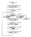
- FIG. 15 is a flowchart illustrating an example of the drawing calculation process of the display controller 31 according to the present embodiment.
- the display controller 31 is configured as shown in FIG.
- a side image (guidance image) indicating the positional relationship between the target surface and the work tool 8 is created according to the flowchart shown in FIG.
- step S31 the target surface information is read from the storage unit 41 as in step S1 in the first embodiment.
- step S32 the target surface graphic 48 obtained from step S31 and the work tool position obtained from the work tool position calculation unit 40c are used to place them in the coordinate system on the image.
- the maximum value [pxmax, pymax] in the vertical direction and the horizontal direction is defined by the size of the screen of the display unit 38, and therefore, at least one of the entire work tool 8 and the target surface graphic 48 is formed.
- the scale Ksc1 and the offset OP1 are determined in order to arrange to include two line segments.
- FIG. 16 shows the first to third monitor points MP1 to MP3, the first and second feature points FP1 and FP2, the third link pin center point LP3, the third cylinder pin center point CP3 on the work machine operation plane (XZ plane) Based on each position of the target surface graphic 48, an outline of a method for arranging the drawing graphic of the large crusher 8d and the target surface graphic 48 in the coordinate system on the image is shown.
- the first monitor point MP1 is a point located at the tip of the work implement frame 67 (a point located on the contour of the work implement frame 67 projected onto the work implement operation plane (XZ plane)). And points located at the tips of the first and second work tool arms 68 and 69 (positioned on the contours of the first and second work tool arms 68 and 69 projected on the work machine operation plane (XZ plane)).
- the central axis of the fourth link pin 75 that pivotally connects the first work tool arm 68 to the work tool frame 67 is the actuator operating plane (XZ plane).
- the first feature point FP1 is a point that intersects with the second work tool arm 69, and the central axis of the fifth link pin 77 that rotatably connects the work tool frame 67 intersects the actuator operating plane (XZ plane).
- the point is set as the second feature point FP2.
- the distances of all the line segments constituting the target surface graphic 48 and the points MP1, MP2, and MP3 are calculated.
- the nearest line segment is set as the nearest neighbor line segment TL1, and the first nearest neighbor target surface point TP1 included in the nearest neighbor line segment is acquired.
- the offset OP1 is calculated by equation (1) so that the center of the acquired maximum and minimum values of the eight points is the origin.
- the scale Ksc1 is obtained by dividing the maximum value [pxmax, pymax] of the screen size by the difference between the maximum value and the minimum value of 8 points on the work machine operation plane (XZ plane).
- the scale Ksc1 is calculated by the equation (2).
- XZ plane work implement operation plane
- step S33 the work tool type information set by the operation unit 37 of the display device 19 using the three points of point mp1, point lp3, and point cp3 indicating the position of the work tool in the coordinate system on the image calculated in step S32. Performs a process of deforming the first drawing figure 81 included in the work tool drawing information associated with the large crusher 8d.
- the work tool drawing information associated with the work tool type information being the large crusher 8d includes the first crusher MP1, the third link pin center point LP3, and the third cylinder pin center point CP3.
- the image information of the first drawing figure 81 representing a part of 8d, and the positions of the first monitor point MP1, the third link pin center point LP3, and the third cylinder pin center point CP3 in the coordinate system on the first drawing figure 81 Point mp1a, the point lp3a, and the coordinate value of the point cp3a.
- FIG. 17 shows a part of the large crusher 8d (work tool frame 67) based on the work tool dimension information of the actually installed crusher 8d and the work tool drawing information indicating the crusher 8d. An example of a method of deforming the first drawing figure 81 to be represented is shown.
- linear mapping is used as in the first embodiment.
- the linear map is expressed by Expression (4).
- the image deformation matrix A1 used for the linear mapping for converting the first drawing figure 81 can be obtained from the work tool size information of the large crusher 8d and the position information at the coordinates of the first drawing figure 81.
- a vector u1 [u1x, u1y] connecting the point lp3 to the point cp3
- a vector u2 [u2x, u2y] connecting the point lp3 to the point mp1
- a vector v1 [v1x, v1y] and a point connecting the point lp3a to the point cp3a
- the image deformation matrix A1 is expressed by equations (5)-(8).
- the inverse matrix P1 ⁇ 1 of the matrix P1 exists when the matrix P1 is regular. For example, as a determination when the matrix P1 is not regular, when the determinant of the matrix P1 is 0, step S34 is performed. The calculation of the drawing calculation unit 40d is terminated without proceeding to the next step.
- the first drawing figure 81 of the large crusher 8d is transformed using the image transformation matrix A1 obtained by the equation (8).
- the first post-deformation drawing figure 81a (shown in FIG. 17B or FIG. 18) is created, and the process proceeds to step S34.
- step S34 the work tool type information set by the operation unit 37 of the display device 19 is roughly divided using the two points of the point mp2 and the point fp1 indicating the position of the work tool in the coordinate system on the image calculated in step S32.
- a process of deforming the second drawing figure 82 included in the work tool drawing information associated with the crusher 8d is performed.
- the work tool drawing information associated with the work tool type information being the crusher 8d is the second drawing figure 82 including the second monitor point MP2 and the first feature point FP1 of the crusher 8d. And the coordinate values of the point mp2b and the point fp1b indicating the positions of the second monitor point MP2 and the first feature point FP1 in the coordinate system on the second drawing figure 82.
- the deformation process of the second drawing figure 82 is performed by dividing the length of the line connecting point mp2b and point fp1b by the length of the line connecting point mp2 and point fp1, and the quotient gives the aspect ratio to the second drawing figure 82. This is done by reducing or enlarging it to be constant.
- step S35 the work tool type information set by the operation unit 37 of the display device 19 is roughly divided using the two points mp3 and fp2 indicating the work tool position in the coordinate system on the image calculated in step S32.
- a process of deforming the third drawing figure 83 included in the work tool drawing information associated with the crusher 8d is performed.
- the work tool drawing information associated with the work tool type information being the large crusher 8d is a third drawing graphic 83 including two points of the third monitor point MP3 and the second feature point FP2 of the large crusher 8d. And the coordinate values of the third monitor point MP3, the point mp3c indicating the position of the second feature point FP2 in the coordinate system on the third drawing figure 83, and the coordinate value of the point fp2c.
- the third drawing figure 83 is deformed by dividing the length of the line connecting the points mp3c and fp2c by the length of the line connecting the points mp3 and fp2, and the quotient gives the aspect ratio to the third drawing figure 83. This is done by reducing or enlarging it to be constant.
- step S36 the first to third modified drawing figures 81a-83a of the large crusher 8d obtained in steps S33, S34, and S35, the work tool 8 on the drawing screen obtained from step S32, and the target surface figure 48 are obtained.
- a drawing image is created on the screen of the display unit 38 from the above arrangement.
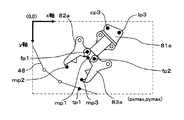
- FIG. 18 shows a state in which the first to third modified drawing figures 81a to 83a representing the large crusher 8d are arranged in the drawing image.
- the first post-deformation drawing figure 81a of the large crusher 8d corresponds to a point mp1a, a point lp3a, and a point cp3a (shown in FIG. 17A) included in the image included in the drawing image.
- a point mp1a a point mp1a
- a point lp3a a point included in the image included in the drawing image.
- a point cp3a shown in FIG. 17A
- the second post-deformation drawing figure 82a of the large crusher 8d includes two points mp2b and fp1b included in the drawing figure, and two points mp2 and fp1 of the corresponding work tool positions included in the drawing image. By matching the points, they are arranged in the drawn image.
- the third post-deformation drawing figure 83a of the large crusher 8d includes two points mp3c and fp2c included in the drawing figure, and two points mp3 and fp2 of the corresponding work tool positions included in the drawing image. By matching the points, they are arranged in the drawn image.
- the image of the target surface figure 48 is drawn within the range that fits on the screen, as in the first embodiment.
- the work tool 8 further includes the second driven portion 69 that is rotatably attached to the base portion 67 via the fourth connecting pin 77, and the construction machine 1 includes the second driven portion 69.
- the second posture detecting device 80 for detecting the posture of the drive unit 69 is further provided, and the dimension information of the work tool 8 includes a second feature point FP2 located on the central axis of the fourth connecting pin 77, and a second driven portion.
- 69 further includes position information of the third monitor point MP3 located at the tip of the 69, and the drawing information of the work tool 8 is a third drawing representing the second driven portion 69 including the second feature point FP2 and the third monitor point MP3.
- the work tool position calculation unit 40 c further includes image information of the figure 83, and the work tool position calculation unit 40 c is based on the dimension information of the work tool 8 and the posture of the second driven unit 69 detected by the second posture detection device 80. And each coordinate value of the third monitor point MP3 is calculated.
- the drawing calculation unit 40d determines that the length of the line segment connecting the second feature point FP2 and the third monitor point MP3 in the drawing figure is the second feature point FP2 and the third monitor point in the coordinate system on the image of the display device 19.
- the third drawing figure 83 is deformed so as to match the length of the line segment connecting with MP3 to create a third deformed drawing figure 83a, and the second feature point FP2 and the third feature point FP2 in the third deformed drawing figure 83a are created.
- the third post-deformation drawing figure 83a is displayed on the screen of the display device 19 so that each position of the monitor point MP3 coincides with each position of the second feature point FP2 and the third monitor point MP3 in the coordinate system on the image. Deploy.
- the work tool 8 (for example, the large crusher 8d) having two driven parts can be displayed on the display device 19 without a sense of incongruity. .
- the crusher 8d is illustrated as the work tool 8, but the base including at least one third monitoring point, the third link pin 22, the third cylinder pin 44, and the monitoring point.
- the base including at least one third monitoring point, the third link pin 22, the third cylinder pin 44, and the monitoring point.
- it is not limited as long as it is two working parts that rotate around one point and a work tool 8 that includes the driving part, and may be replaced by a grapple or the like.
- the third link pin 22, the third cylinder pin 44, and the first drawing figure 81 that is an image of the base including at least one monitor point, and at least one monitor point are included in the working tool 8.
- the second and third drawing figures 82 and 83 which are images of two driven parts that rotate around a certain point, are drawn, but a driving part such as a hydraulic cylinder may be drawn.
- a hydraulic excavator 1 according to a fifth embodiment of the present invention will be described with reference to FIGS.
- the hydraulic excavator 1 according to this embodiment includes a bucket as the work tool 8 as in the second embodiment.
- the setting method of at least one monitor point different from the first monitor point MP1 in the work tool 8 is omitted, but in the present embodiment, at least one different from the first monitor point MP1 is used.
- An easy setting method of monitor points will be described.
- FIG. 19 is a block diagram illustrating a configuration of the calculation unit 40 of the display controller 31 according to the present embodiment.
- the calculation unit 40 of the display controller 31 further includes a monitor point setting calculation unit 40e.
- the monitor point setting calculation unit 40e is information on the size of the work tool set by the operation unit 37 of the display device 19 and the dimensions of the boom 6, the arm 7 and the work tool 8 relating to the first monitor point MP1, for example, the third link pin center. Based on the calculation result of the work tool position calculation unit 40c such as the length Lmp1 from the point LP3 to the first monitor point MP1, information on the dimensions of at least one monitor point different from the first monitor point MP1 is set.
- FIG. 20 is a flowchart illustrating an example of the monitor point setting calculation process of the display controller 31 according to the present embodiment.
- the work tool 8 attached to the excavator 1 has a plurality of monitor points, dimension information of one monitor point (first monitor point MP1) among them is already set, and other monitor points.
- first monitor point MP1 dimension information of one monitor point
- other monitor points other monitor points.
- step S41 upon receiving a signal for starting the monitor point setting calculation process from the operation unit 37, the display unit 38 is caused to touch the fixed mark 86 that does not move even when the work tool 8 touches the first monitor point MP1. indicate.
- step S42 upon receiving a signal indicating that the operator has confirmed that the first monitor point MP1 and the mark 86 are in contact with each other from the operation unit 37, the work tool position calculation unit 40c performs the work implement of the first monitor point MP1.
- the position on the operation plane (XZ plane) is calculated, and the position [Xmp1a, Zmp1a] of the mark 86 that is in contact with the first monitor point MP1 is stored in the storage unit 41.
- a warning is displayed on the display unit 38 so as not to move other than the work implement 3 until the monitor point setting calculation processing is completed so that the positional relationship between the center of the mark and the mark 86 does not change.
- step S43 the setting process of at least one monitor point different from the first monitor point MP1 and the kth monitor point (the initial value of k is 2) is started.
- the set monitor point When receiving a signal indicating that the setting of the monitor point is completed from the operation unit 37, the set monitor point is stored in the storage unit 41, and the process is terminated.
- step S44 the mark 86 is displayed on the display unit 38 so that the point inside the work tool 8 set as the kth monitor point, here the second monitor point MP2, is touched.
- step S45 upon receiving a signal indicating that the operator has confirmed that the second monitor point MP2 and the mark 86 are in contact with each other from the operation unit 37, the work tool position calculation unit 40c is connected to the third link pin center point LP3.
- the position of the first monitor point MP1 on the work machine operation plane (XZ plane) is calculated, and the storage unit stores the position [Xlp3b, Zlp3b] of the third link pin center point LP3 and the position [Xmp1b, Zmp1b] of the first monitor point MP1. 41.
- step S46 the position of the second monitor point MP2 in the work tool 8 is determined from the position of the mark 86 stored in step S42 and the position of the third link pin LP3 and the first monitor point MP1 stored in step S45. Calculate.
- FIG. 21 shows the work tool 8 when the position of the first monitor point MP1 is aligned with the position of the fixed mark 86 and the work tool 8 when the position of the second monitor point MP2 is aligned with the position of the mark 86. Is shown by a solid line.
- monitor point setting calculation unit 40e sets w1 as a vector connecting the third monitor pin MP3 to the first monitor point MP1 from the third link pin center point LP3, and w2 as a vector connecting the second monitor point MP2 from the third link pin center point CP3. 2
- the position of the monitor point MP2 inside the work tool 8 is calculated as the length Lmp2 of the vector w2 and the angle ⁇ mp2 formed by the vectors w1 and w2.
- the length Lmp2 of the vector w2 is expressed by the following formula.
- angle ⁇ mp2 formed by the vectors w1 and w2 is expressed by the following equation using the inner product.
- step S47 a monitor point is further set from the operation unit 37, or a signal indicating that the setting of the monitor point is completed is displayed on the display unit 38, and the input of the operation unit 37 is awaited. Do.
- the monitor point is further set, the numerical value of k is increased by 1.
- the setting process of the third monitor point MP3 is performed in the same manner as the setting process of the second monitor point MP2.
- step S45 upon receiving a signal indicating that the operator has confirmed that the third monitor point MP3 and the mark 86 are in contact with each other from the operation unit 37, the work tool position calculation unit 40c is connected to the third link pin 22 and the first link.
- the position of the monitor point MP1 on the work machine operation plane (XZ plane) is calculated, and the position [Xlp3c, Zlp3c] of the third link pin center point LP3 and the position [Xmp1c, Zmp1c] of the first monitor point MP1 are stored in the storage unit 41.
- step S46 the third monitor is determined from the position of the mark 86 stored in step S42 and the positions of the third link pin center point LP3 and the first monitor point MP1 stored in step S45 in the setting process of the third monitor point MP3.
- the position of the point MP3 inside the work tool 8 is calculated.
- the position of the three monitor points MP3 inside the work tool 8 is calculated as the length Lmp3 of the vector w3 and the angle ⁇ mp3 formed by the vectors w1 and w3.
- the length Lmp3 of the vector w3 is expressed by the following formula.
- angle ⁇ mp3 formed by the vectors w1 and w3 is expressed by the following equation using the inner product.
- step S47 after the setting of the third monitor point MP3 is completed, a signal indicating that the setting of the monitor point is completed is input, and the setting process is terminated.
- the work tool position calculation unit 40c sets the coordinate value of the fixed mark 86 in a state where the position of the first monitor point MP1 in which the dimension information is set is matched with the position of the fixed mark 86.
- the display controller 31 performs the calculation from the first connection point LP3 to the first connection point LP3 in a state where the positions of the unset monitor points MP2 and MP3 for which the dimension information on the work tool 8 is not set are aligned with the fixed mark 86.
- An angle between the first vector w1 connecting the monitor points MP1 and the second vectors w2 and w3 connecting the fixed mark 86 from the first connection point LP3 and the lengths of the second vectors w2 and w3 are calculated, and unset monitor points It further has a monitor point setting calculation unit 40e that is set as dimension information of MP2 and MP3.
- the coordinate value of the fixed mark 86 is set in a state where the position of the first monitor point MP1 in which the dimension information is set is aligned with the fixed mark 86.
- the calculation unit 40c calculates the position on the work machine operation plane (XZ plane), and the monitor point setting calculation process is performed so that the positional relationship between the center of the first link pin 20 and the mark 86 on the display unit 38 does not change. However, if the excavator 1 includes the correction information receiver 36 and the antennas 23a and 23b, the work tool position calculation unit 40c calculates the warning. Since the position in the global coordinate system is used by the monitor point setting calculation unit 40e, the movement of the position of the center of the first link pin 20 that is the origin can be grasped. Setting calculation processing.
- the Example of this invention is not limited to an above-described Example, Various modifications are included.
- the rotation angle of the boom 6, the arm 7 and the work tool 8 is detected by the IMU.
- a linear encoder for measuring the cylinder stroke length is mounted on the first-3 cylinder 9-11.
- the rotation angle of the boom 6, the arm 7 and the work tool 8 may be obtained by link calculation from the length of the cylinder extended and contracted and the vehicle body dimension parameter stored in the storage unit 41.
- SYMBOLS 1 Hydraulic excavator (construction machine), 2 ... Vehicle main body, 3 ... Working machine, 4 ... Upper turning body, 5 ... Lower traveling body, 6 ... Boom, 7 ... Arm, 8 ... Work tool, 8a ... Hydraulic breaker, 8b DESCRIPTION OF SYMBOLS Bucket, 8c ... Split crusher, 8d ... Split crusher, 9 ... 1st cylinder, 10 ... 2nd cylinder, 11 ... 3rd cylinder, 12 ... cab, 13 ... Swing motor, 14 ... Hydraulic control device , 15a ... crawler belt, 15b ... crawler belt, 15c ... display control unit, 16a ... travel motor, 16b ...
- Calculation unit 40a Global position calculation unit 40b ... Posture calculation unit 40c ... Work tool position calculation unit, 40d: Drawing operation unit, 41 ... Storage unit, 42 ... First cylinder pin, 43 ... Second cylinder pin, 44 ... Third cylinder pin (second connecting pin), 48 ... Target surface figure, 49 ... First drawing figure , 49a ... first deformed drawing figure, 53 ... first drawing figure, 53a ... first transformed drawing figure, 54 ... second drawing figure, 54a ... second transformed drawing figure, 55 ... third drawing figure, 55a ... Drawing figure after third transformation, 56 ... Bottom surface 57 ... Work tool frame (base part), 58 ... Work tool arm, 59 ... Fourth link pin (third connection pin), 63 ... Fourth cylinder, 64 ...
- Fourth rotation angle sensor (first posture detection device), 65 ... 1st drawing figure, 65a ... Drawing figure after 1st modification, 66 ... 2nd drawing figure, 66a ... Drawing figure after 2nd transformation, 67 ... Work tool frame (base), 68 ... 1st work tool arm (1st Driven part), 69 ... second working tool arm (second driven part), 75 ... fourth link pin (third connecting pin), 76 ... fourth cylinder, 77 ... fifth link pin (fourth connecting pin) , 78... 5th cylinder, 79... 4th rotation angle sensor (first attitude detection device), 80... 5th rotation angle sensor (second attitude detection device), 81. Post-drawn figure, 82 ... second drawn figure, 82a ...
- External storage device CP3 ... 3rd cylinder pin center point (2nd connection point), FP1 ... 1st feature point, FP2 ... Second feature point, LP3 ... third link pin center point (first connection point), MP1 ... first monitor point, MP2 ... second monitor point (unset monitor point), MP3 ... third monitor point (unset monitor) Point), OP1 ... offset, w1 ... first vector, w2, w3 ... second vector.
Landscapes
- Engineering & Computer Science (AREA)
- Structural Engineering (AREA)
- Mining & Mineral Resources (AREA)
- Civil Engineering (AREA)
- General Engineering & Computer Science (AREA)
- Mechanical Engineering (AREA)
- Component Parts Of Construction Machinery (AREA)
- Operation Control Of Excavators (AREA)
Priority Applications (4)
| Application Number | Priority Date | Filing Date | Title |
|---|---|---|---|
| CN201880054028.XA CN111032971B (zh) | 2018-03-15 | 2018-12-17 | 工程机械 |
| EP18910095.1A EP3767042B1 (de) | 2018-03-15 | 2018-12-17 | Baumaschine |
| US16/644,309 US11505923B2 (en) | 2018-03-15 | 2018-12-17 | Construction machine |
| KR1020207004665A KR102388110B1 (ko) | 2018-03-15 | 2018-12-17 | 건설 기계 |
Applications Claiming Priority (2)
| Application Number | Priority Date | Filing Date | Title |
|---|---|---|---|
| JP2018-048642 | 2018-03-15 | ||
| JP2018048642A JP6854255B2 (ja) | 2018-03-15 | 2018-03-15 | 建設機械 |
Publications (1)
| Publication Number | Publication Date |
|---|---|
| WO2019176208A1 true WO2019176208A1 (ja) | 2019-09-19 |
Family
ID=67907619
Family Applications (1)
| Application Number | Title | Priority Date | Filing Date |
|---|---|---|---|
| PCT/JP2018/046416 Ceased WO2019176208A1 (ja) | 2018-03-15 | 2018-12-17 | 建設機械 |
Country Status (6)
| Country | Link |
|---|---|
| US (1) | US11505923B2 (de) |
| EP (1) | EP3767042B1 (de) |
| JP (1) | JP6854255B2 (de) |
| KR (1) | KR102388110B1 (de) |
| CN (1) | CN111032971B (de) |
| WO (1) | WO2019176208A1 (de) |
Families Citing this family (6)
| Publication number | Priority date | Publication date | Assignee | Title |
|---|---|---|---|---|
| JP6854255B2 (ja) * | 2018-03-15 | 2021-04-07 | 日立建機株式会社 | 建設機械 |
| JP7156561B2 (ja) * | 2020-02-05 | 2022-10-19 | 株式会社タダノ | 性能情報サーバ、作業機表示操作アプリケーション、機種情報の提供方法、機種情報の取得方法、及び機種情報取得システム |
| CN115777037A (zh) * | 2020-05-07 | 2023-03-10 | 现代斗山英维高株式会社 | 挖掘机及其控制方法 |
| CN113821884B (zh) * | 2021-08-31 | 2024-01-26 | 郑州恒达智控科技股份有限公司 | 一种基于液压支架多维姿态监测的数字孪生方法及系统 |
| EP4417757A4 (de) * | 2021-12-03 | 2025-03-26 | Kobelco Construction Machinery Co., Ltd. | Bildanzeigesystem, fernbetriebsunterstützungssystem und bildanzeigeverfahren |
| JP2025037124A (ja) * | 2023-09-05 | 2025-03-17 | コベルコ建機株式会社 | 作業支援システムおよび作業支援方法 |
Citations (4)
| Publication number | Priority date | Publication date | Assignee | Title |
|---|---|---|---|---|
| JP2002140731A (ja) * | 2000-11-01 | 2002-05-17 | Esuroku:Kk | 画像処理装置および方法、画像処理システム、記録媒体 |
| JP2010253049A (ja) * | 2009-04-24 | 2010-11-11 | Toshiba Corp | 放射線治療装置および放射線透視装置 |
| JP2016076444A (ja) * | 2014-10-08 | 2016-05-12 | 化研テック株式会社 | 導電性ペースト及び電磁波シールド部材 |
| JP6080983B2 (ja) | 2015-10-23 | 2017-02-15 | 株式会社小松製作所 | 作業機械の表示システム、作業機械及び表示方法 |
Family Cites Families (13)
| Publication number | Priority date | Publication date | Assignee | Title |
|---|---|---|---|---|
| GB2413314B (en) * | 2003-09-02 | 2006-07-26 | Komatsu Mfg Co Ltd | Construction target indicator device |
| JP5367665B2 (ja) * | 2010-09-17 | 2013-12-11 | 日立建機株式会社 | 作業機械の表示システム |
| KR101735116B1 (ko) * | 2011-01-24 | 2017-05-15 | 두산인프라코어 주식회사 | 건설중장비의 운행정보 기록장치 |
| JP5054832B2 (ja) * | 2011-02-22 | 2012-10-24 | 株式会社小松製作所 | 油圧ショベルの表示システム及びその制御方法 |
| JP5624101B2 (ja) * | 2012-10-05 | 2014-11-12 | 株式会社小松製作所 | 掘削機械の表示システム、掘削機械及び掘削機械の表示用コンピュータプログラム |
| JP5848451B1 (ja) * | 2014-06-02 | 2016-01-27 | 株式会社小松製作所 | 建設機械の制御システム、建設機械、及び建設機械の制御方法 |
| KR101762044B1 (ko) * | 2014-09-09 | 2017-07-26 | 가부시키가이샤 고마쓰 세이사쿠쇼 | 굴삭 기계의 표시 시스템, 굴삭 기계 및 화상 표시 방법 |
| JP6777375B2 (ja) * | 2015-03-05 | 2020-10-28 | 株式会社小松製作所 | 作業機械の画像表示システム、作業機械の遠隔操作システム及び作業機械 |
| JP6316770B2 (ja) * | 2015-04-15 | 2018-04-25 | 日立建機株式会社 | 建設機械 |
| CN105829616B (zh) * | 2015-12-09 | 2018-02-09 | 株式会社小松制作所 | 作业车和倾斜角度的取得方法 |
| JP2017115370A (ja) | 2015-12-22 | 2017-06-29 | コベルコ建機株式会社 | 建設機械のアタッチメントの形状データ作成方法 |
| JP6854255B2 (ja) * | 2018-03-15 | 2021-04-07 | 日立建機株式会社 | 建設機械 |
| JP6942671B2 (ja) * | 2018-04-26 | 2021-09-29 | 株式会社小松製作所 | 寸法特定装置および寸法特定方法 |
-
2018
- 2018-03-15 JP JP2018048642A patent/JP6854255B2/ja active Active
- 2018-12-17 EP EP18910095.1A patent/EP3767042B1/de active Active
- 2018-12-17 WO PCT/JP2018/046416 patent/WO2019176208A1/ja not_active Ceased
- 2018-12-17 KR KR1020207004665A patent/KR102388110B1/ko active Active
- 2018-12-17 US US16/644,309 patent/US11505923B2/en active Active
- 2018-12-17 CN CN201880054028.XA patent/CN111032971B/zh active Active
Patent Citations (4)
| Publication number | Priority date | Publication date | Assignee | Title |
|---|---|---|---|---|
| JP2002140731A (ja) * | 2000-11-01 | 2002-05-17 | Esuroku:Kk | 画像処理装置および方法、画像処理システム、記録媒体 |
| JP2010253049A (ja) * | 2009-04-24 | 2010-11-11 | Toshiba Corp | 放射線治療装置および放射線透視装置 |
| JP2016076444A (ja) * | 2014-10-08 | 2016-05-12 | 化研テック株式会社 | 導電性ペースト及び電磁波シールド部材 |
| JP6080983B2 (ja) | 2015-10-23 | 2017-02-15 | 株式会社小松製作所 | 作業機械の表示システム、作業機械及び表示方法 |
Non-Patent Citations (1)
| Title |
|---|
| See also references of EP3767042A4 |
Also Published As
| Publication number | Publication date |
|---|---|
| CN111032971A (zh) | 2020-04-17 |
| EP3767042A1 (de) | 2021-01-20 |
| EP3767042A4 (de) | 2021-12-15 |
| US20210047805A1 (en) | 2021-02-18 |
| JP6854255B2 (ja) | 2021-04-07 |
| CN111032971B (zh) | 2022-02-25 |
| JP2019157569A (ja) | 2019-09-19 |
| US11505923B2 (en) | 2022-11-22 |
| EP3767042B1 (de) | 2023-04-26 |
| KR20200033894A (ko) | 2020-03-30 |
| KR102388110B1 (ko) | 2022-04-19 |
Similar Documents
| Publication | Publication Date | Title |
|---|---|---|
| KR102388110B1 (ko) | 건설 기계 | |
| JP6068730B2 (ja) | 作業機械、及び作業機械の作業機パラメータ補正方法 | |
| CN103080427B (zh) | 液压挖掘机的校正装置及液压挖掘机的校正方法 | |
| JP5237408B2 (ja) | 油圧ショベルの較正システム及び較正方法 | |
| JP5841300B1 (ja) | 作業機械の較正装置、及び作業機械の作業機パラメータの較正方法 | |
| CN110300827B (zh) | 工程机械 | |
| CN105339560B (zh) | 挖掘机械的控制系统以及挖掘机械 | |
| JP7223823B2 (ja) | 旋回作業車 | |
| KR20160003678A (ko) | 유압 쇼벨의 교정 시스템 및 교정 방법 | |
| KR20150142031A (ko) | 굴삭 기계의 표시 시스템, 굴삭 기계 및 굴삭 기계의 표시 방법 | |
| JP2012202062A (ja) | 油圧ショベルの較正装置及び油圧ショベルの較正方法 | |
| CN110352280B (zh) | 挖掘机械的显示系统、挖掘机械及挖掘机械的显示方法 | |
| CN115244256B (zh) | 显示系统、存储介质以及显示系统的控制方法 | |
| EP4417757A1 (de) | Bildanzeigesystem, fernbetriebsunterstützungssystem und bildanzeigeverfahren | |
| CN115087781B (zh) | 显示系统、存储介质以及显示控制方法 | |
| AU2021354304B2 (en) | Display control device and display method | |
| CN115398066A (zh) | 施工方法及施工系统 | |
| AU2021352215B2 (en) | Display control device and display control method | |
| WO2022138058A1 (ja) | 作業機械の状態管理装置 | |
| JP7739072B2 (ja) | 作業機械 |
Legal Events
| Date | Code | Title | Description |
|---|---|---|---|
| 121 | Ep: the epo has been informed by wipo that ep was designated in this application |
Ref document number: 18910095 Country of ref document: EP Kind code of ref document: A1 |
|
| ENP | Entry into the national phase |
Ref document number: 20207004665 Country of ref document: KR Kind code of ref document: A |
|
| NENP | Non-entry into the national phase |
Ref country code: DE |
|
| WWE | Wipo information: entry into national phase |
Ref document number: 2018910095 Country of ref document: EP |
|
| ENP | Entry into the national phase |
Ref document number: 2018910095 Country of ref document: EP Effective date: 20201015 |