WO2019176251A1 - Kit collecteur d'échantillon - Google Patents
Kit collecteur d'échantillon Download PDFInfo
- Publication number
- WO2019176251A1 WO2019176251A1 PCT/JP2019/000506 JP2019000506W WO2019176251A1 WO 2019176251 A1 WO2019176251 A1 WO 2019176251A1 JP 2019000506 W JP2019000506 W JP 2019000506W WO 2019176251 A1 WO2019176251 A1 WO 2019176251A1
- Authority
- WO
- WIPO (PCT)
- Prior art keywords
- receiving
- receiving portion
- collection kit
- specimen
- kit according
- Prior art date
- Legal status (The legal status is an assumption and is not a legal conclusion. Google has not performed a legal analysis and makes no representation as to the accuracy of the status listed.)
- Ceased
Links
Images


Classifications
-
- G—PHYSICS
- G01—MEASURING; TESTING
- G01N—INVESTIGATING OR ANALYSING MATERIALS BY DETERMINING THEIR CHEMICAL OR PHYSICAL PROPERTIES
- G01N1/00—Sampling; Preparing specimens for investigation
- G01N1/02—Devices for withdrawing samples
- G01N1/04—Devices for withdrawing samples in the solid state, e.g. by cutting
-
- G—PHYSICS
- G01—MEASURING; TESTING
- G01N—INVESTIGATING OR ANALYSING MATERIALS BY DETERMINING THEIR CHEMICAL OR PHYSICAL PROPERTIES
- G01N33/00—Investigating or analysing materials by specific methods not covered by groups G01N1/00 - G01N31/00
- G01N33/48—Biological material, e.g. blood, urine; Haemocytometers
Definitions
- the present invention relates to a specimen collection kit.
- a sampler such as a subject or a caregiver collects a part of the stool as a sample.
- This sample collection operation is, for example, rubbing the surface of feces excreted in a cup-shaped receiving part set in a toilet bowl over a wide range with the tip of a rod-shaped collection tool, which is psychological for the collector. It is an unpleasant work with great resistance. For this reason, there has been a demand to simplify the sample collection operation as much as possible.
- Patent Document 1 includes a cup-shaped receiving part, and a stool receiving tool having a mounting part for setting the receiving part on the toilet bowl, and a rod-shaped sampling tool, with the tip arranged in the receiving part,
- a specimen collection kit is described in which a collection tool is integrally and detachably held in a receiving part.
- the subject or the caregiver sets the receiving part on the toilet bowl via the attachment part in a state where the collection tool is held by the receiving part.
- the subject sits on the toilet and excretes feces in the receiving part.
- a part of the stool as a specimen naturally adheres to the tip of the collection tool arranged in the receiving part.
- the sampler removes the collection tool with the sample attached to the tip from the receiving part. Since the operation of rubbing the surface of the stool with the tip of the collection tool is eliminated, simplification of the sample collection operation can be promoted.
- Patent Document 1 the work of rubbing the stool surface with the tip of the sampling tool is certainly eliminated. However, it is the same as when the surface of the stool is rubbed with the tip of the sampling tool in that the stool remaining in the receiving part enters the eyes of the collector. For this reason, the problem still remains that the collector feels uncomfortable in the sample collection operation.
- An object of the present invention is to provide a sample collection kit that can further reduce the chance that the sampler feels uncomfortable in the sample collection operation.
- the sample collection kit of the present invention is a cup shape having a receptacle for receiving stool in the sample collection kit for collecting a part of stool excreted by a subject as a sample.
- a stool receiver having a receiving part that is capable of closing the stool and a mounting part for setting the receiving part on the toilet bowl, and an attaching part that comes in contact with a part of the stool and a part of the stool adheres as a specimen,
- a sampling tool having a gripping part to be gripped by the collector, and at least a part of the sampling tool including the attaching part can be integrally and removable from the receiving part in a state where the attaching part is arranged in the receiving part. Retained.
- the feces receiver is preferably formed of a material in which at least the receiving part is opaque.
- a closing member for closing the receiving port is attached to the receiving portion.
- the closing member is preferably a tie string sewn around the receptacle, or a tie strap tied around the receptacle.
- the gripping part preferably functions as a cap that seals the opening of the sample container.
- the collection tool is preferably a rod having an attachment portion formed at the tip and a gripping portion formed at the proximal end.
- the receiving portion is formed with an insertion hole whose tip is inserted into the receiving portion.
- the cover which covers the holding part exposed outside the receiving part from the insertion hole and closes the insertion hole is attached to the outer peripheral surface of the receiving part so as to be peelable.
- the insertion hole is formed in the side part of the receiving part, and the adhering part is preferably arranged at a height of 3 cm or less from the inner peripheral surface of the bottom part of the receiving part.
- the insertion hole is formed in the side part of a receiving part, and the protrusion length of the stick
- rod from an insertion hole to an adhesion part is 50% or more of the distance from the insertion hole to the center of the bottom part of a receiving part. preferable.
- the collection tool preferably includes a main body that has an attachment portion and is held by the receiving portion, and a collection body that has a gripping portion and collects the main body from the receiving portion.
- the main body is a rigid plate having an attachment portion formed on one side, and the recovery body has a coupling portion that is coupled to the plate, and a gripping portion is formed at the other end opposite to the coupling portion.
- the receiving portion is formed with an opening for exposing the adhering portion of the plate to the receiving portion.
- the cover which covers the board exposed outside the receiving part from the exposure opening on the outer peripheral surface of the receiving part and closes the exposing opening is detachably attached.
- the exposure opening is preferably formed at a position of 3 cm or less from the inner peripheral surface of the bottom of the receiving part on the side part of the receiving part.
- the main body is a flexible tape with an attachment portion formed on one side, and the recovery body has an engaging portion that engages with one end of the tape, and is gripped at the other end opposite to the engaging portion. It is preferable that the portion is formed and the tape is wound thereon. In this case, it is preferable that the receiving portion is provided with an exposure opening that is exposed in the receiving portion of the tape, and the tape is attached to the outer peripheral surface of the receiving portion so as to be able to peel off the opening.
- the exposure opening is preferably formed at a position of 3 cm or less from the inner peripheral surface of the bottom of the receiving part on the side part of the receiving part.
- the sample collection kit in which at least a part of the collection tool including the attachment part to which a part of the stool adheres as a sample is integrally and detachably held in the receiving part that receives the stool of the stool receiver Since the stool receiving port of the receiving part can be closed, it is possible to provide a sample collection kit that can further reduce the chance that the sampler feels uncomfortable in the sample collection operation.
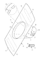
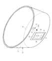
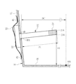
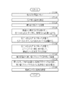
- sample collection kit It is an external view of a sample collection kit. It is an enlarged view of the part of the receiving part to which the collection tool was attached. It is an expanded sectional view of the part of the receiving part to which the collection tool was attached. It is a flowchart which shows the sample collection procedure using a sample collection kit. It is a figure which shows the state which is going to set a stool receptacle to a toilet bowl. It is a figure which shows the state which set the stool receptacle to the toilet bowl. It is a figure which shows the state by which feces were excreted in the receiving part. It is a figure which shows the state by which the receptacle was obstruct
- FIG. 12A is a diagram illustrating a procedure for storing a sampling tool in a sample container.
- FIG. 12A shows a state in which the disposable cap is removed from the sample container and discarded, and FIG.
- FIG. 12B shows a state in which the sampling tool is stored in the sample container.
- 5 shows a state in which the collection tool is accommodated and the opening of the sample container is sealed with a gripping portion instead of the disposable cap.
- FIG. 19A is a state diagram excerpting the specimen collection procedure of the second embodiment
- FIG. 19A is a state where the cover is peeled off from the receiving portion
- FIG. 19B is a state where the plate is peeled off from the outer peripheral surface of the side portion and coupled to the plate
- FIG. 19C shows a state in which the disposable cap is removed from the sample container and is discarded, and the sampling tool is about to be stored in the sample container.
- FIG. 19D shows a state where the sampling tool is stored in the sample container and is disposable. A state in which the opening of the sample container is sealed with a grip portion instead of a cap is shown.
- FIG. 24A is a state diagram excerpting the specimen collection procedure of the third embodiment
- FIG. 24A is a state in which one end of the tape is about to be engaged with the engaging portion of the recovery body
- FIG. 24C shows a state in which the disposable cap is removed from the sample container and is discarded, and the sampling tool is to be stored in the sample container.
- FIG. 24D shows the sampling tool in the sample container. The state where the opening of the specimen container is hermetically sealed by the grip portion instead of the disposable cap is shown.
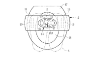
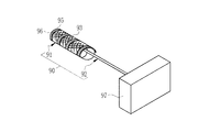
- the sample collection kit 10 includes a stool receiver 11, a collection tool 12, and a sample container 13.
- the sample collection kit 10 uses a part of the stool F (see FIG. 7 and the like) excreted by the subject S (see FIG. 7) as a sample SP for the fecal occult blood test for examining the presence of blood in the stool sample. (See FIG. 10 etc.).
- the specimen collection kit 10 is used by a specimen SP collector such as the subject S or a caregiver thereof.
- the stool receiver 11 is a tool for receiving the stool F excreted by the subject S.
- the stool receiver 11 has a receiving part 14 and an attachment part 15.
- the receiving portion 14 has a cup shape having a receiving port 16, a side portion 17, and a bottom portion 18.
- the receiving port 16 has an elliptical shape with a large opening at the top.
- the side portion 17 has a substantially elliptical cylindrical shape that extends downward from the receiving port 16 so that the width gradually decreases.
- the bottom portion 18 is connected to the side portion 17 so as to be substantially orthogonal to each other, and is formed so as to close the opening facing the receiving port 16.
- the receiving unit 14 receives the stool F at the receiving port 16 and causes the stool F to remain on the bottom 18.
- the mounting portion 15 is for setting the receiving portion 14 to the toilet 45 (see FIG. 5), and is a wing-like sheet projecting symmetrically from the receiving port 16.
- a seal 19 is provided on the back surface of the mounting portion 15. The seal 19 is covered with a protective sheet (not shown) before the stool receiver 11 is used, and the protective sheet is peeled off and exposed when the stool receiver 11 is used.
- the stool receiver 11 has a form capable of closing the receiving port 16 and is formed of an opaque material.
- the stool receiver 11 is flexible and has a visible light transmittance of 0 or close to 0, or has flexibility and scatters or reflects visible light so that the inside It is made of a material that cannot be seen.
- the feces receiver 11 is a paper formed by entwining fibers of plants or the like, or a cloth formed by weaving or knitting fibers.
- the stool receiver 11 is compactly folded before use and is unfolded by the collector at the time of use. Further, the stool receiver 11 has water decomposability so that the stool F can be poured into the water of the stool 45 after collection of the sample SP.
- the part formed with an opaque material should just be only the receiving part 14, and the attaching part 15 may be formed with a transparent material.
- a binding string 20 is attached directly below the receiving port 16 of the receiving unit 14.
- the strap 20 is sewn around the receiving port 16 as shown in an enlarged view in a circle surrounded by a one-dot chain line.
- the receptacle 16 is closed by pulling both ends of the binding string 20. That is, the strap 20 functions as a closing member for closing the receiving port 16.
- the collection tool 12 is a tool for collecting a part of the stool F retained in the receiving portion 14 as a specimen SP.
- the collection tool 12 is made of plastic, for example.
- the collection tool 12 is a rod having a T-shaped longitudinal section in which a sticking portion 21 is formed at the tip of a cylindrical rod-like portion, and a rectangular parallelepiped gripping portion 22 is formed at the base end opposite to the sticking portion 21. is there.
- the adhering portion 21 contacts a part of the stool F in the receiving portion 14. Thereby, a part of the stool F adheres to the attaching part 21 as the specimen SP.
- the adhering portion 21 has an uneven shape having a plurality of annular grooves, and the specimen SP is easily attached.
- the gripping part 22 is gripped by the collector.
- the grip portion 22 is exposed to the outside of the receiving portion 14 on the outer peripheral surface of the side portion 17 of the receiving portion 14 and is covered with a peelable rectangular cover 23.
- the rod-shaped part of the collection tool 12 including the attaching part 21 other than the grip part 22 is inserted into the receiving part 14 (see also FIGS. 2 and 3). That is, at least a part (in this case, a rod-like portion) of the collection tool 12 including the attaching portion 21 is integrally held by the receiving portion 14 in a state where the attaching portion 21 is disposed in the receiving portion 14.
- the sample container 13 accommodates at least a part of the collection tool 12 after collection of the sample SP removed from the receiving portion 14, that is, a rod-shaped portion (see FIG. 12).
- the specimen container 13 stores a diluent 24 in which the specimen SP is suspended.
- the sample container 13 has an opening 25 for receiving the collection tool 12.
- the opening 25 is sealed with a disposable cap 26 before the collection tool 12 is accommodated.
- the specimen container 13 is suspended with a scraping part that scrapes off excess specimen SP adhering to the adhering part 21 from the adhering part 21 before the diluent 24, and the specimen SP.
- a filter for filtering the diluted liquid 24, a storage section for retaining the filtered diluted liquid 24 as a test liquid, and the like are provided.
- the disposable cap 26 and the gripping part 22 of the collection tool 12 have the same size and the same structure.
- the gripper 22 seals the opening 25 instead of the disposable cap 26 when the rod-shaped portion of the collection tool 12 is accommodated in the sample container 13 (see FIG. 12). That is, the gripping part 22 functions as a cap that seals the opening 25 of the sample container 13.
- general methods such as screwing, fitting, and press fit, can be used as a sealing method of the opening 25 by the holding part 22 and the disposable cap 26.
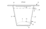
- FIG. 2 and FIG. 3 which are enlarged views of the portion of the receiving portion 14 to which the collection tool 12 is attached, an insertion hole 40 is formed in the side portion 17 of the receiving portion 14. Through the insertion hole 40, the distal end of the collection tool 12 on which the attachment portion 21 is formed is inserted into the receiving portion 14.
- the cover 23 is coated with an adhesive 42 (indicated by hatching) in an annular region 41 that is slightly smaller than the outer periphery of the back surface. With this adhesive 42, the cover 23 is detachably attached to the outer peripheral surface of the side portion 17 of the receiving portion 14. The cover 23 covers the grip portion 22 exposed to the outside of the receiving portion 14 from the insertion hole 40 and closes the insertion hole 40 in an airtight and liquid-tight manner.
- an adhesive 42 indicated by hatching
- the annular region 41 is slightly separated from the outer periphery. For this reason, the upper part of the cover 23 can be easily hit with a finger.
- the cover 23 can be peeled off from the outer peripheral surface of the side portion 17 using this upper portion as a clue.
- the gripping portion 22 is not bonded and fixed to the side portion 17.
- the cover 23 is bonded to the side portion 17 so that the grip portion 22 does not move after the grip portion 22 is in close contact with the side portion 17 without any gap.
- the gripping part 22 is held by the cover 23 in a state of being in close contact with the side part 17 without a gap.
- at least a part of the collection tool 12 including the attaching portion 21, that is, a rod-like portion is integrally and detachably held by the receiving portion 14 in a state where the attaching portion 21 is disposed in the receiving portion 14.
- the grip portion 22 may be detachably attached to the side portion 17 with an adhesive, and the insertion hole 40 may be closed with the grip portion 22 itself.
- the cover 23 may or may not be attached.
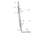
- the height H1 of the adhering portion 21 (the tip 21A of the adhering portion 21 at the highest position) from the inner peripheral surface of the bottom portion 18 of the receiving portion 14 is an average of the stool F of a general adult.
- the height is 3 cm or less. That is, the adhering portion 21 is disposed at a height of 3 cm or less from the inner peripheral surface of the bottom portion 18.
- the height H1 is the height of the adhesion portion 21 from the lowest position of the inner peripheral surface of the bottom portion 18.
- the protruding length of the rod from the insertion hole 40 (the end 40A of the insertion hole 40 at the lowest position) to the attachment portion 21 (the most advanced portion 21B of the attachment portion 21) is received from the insertion hole 40 (end 40A).
- PL is 50% or more of DC (PL ⁇ 0.5 DC).
- the bottom portion 18 has a size that can fit an average single stool F of a general adult, and DC is, for example, 3.5 cm. In this case, PL is 1.75 cm or more.
- the sampler sets the receiving portion 14 on the toilet 45 via the attachment portion 15 (step ST100). More specifically, the attachment portion 15 is adhered and fixed to the surface of the toilet seat 47 with the seal 19 so that the receiving portion 14 is arranged in a floating manner toward the center rear side of the water reservoir portion 46.
- the subject S sits at a position where the center 18A of the bottom portion 18 of the receiving portion 14 and the anus substantially coincide with each other and urine does not enter the receiving portion 14.
- F is excreted (step ST110).
- the receiving portion 14 may be set in the toilet bowl 45 by sandwiching the attachment portion 15 between the toilet bowl 45 and the toilet seat 47. In this case, the seal 19 is unnecessary.
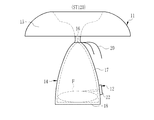
- the stool F enters the receiving part 14 from the receiving port 16 and stays at the bottom 18 of the receiving part 14 as shown in FIG.
- illustration of the cover 23 is abbreviate
- the attachment portion 21 of the sampling tool 12 is disposed at a height of 3 cm or less from the inner peripheral surface of the bottom portion 18 of the receiving portion 14.
- the protruding length PL of the rod from the insertion hole 40 to the attachment portion 21 is 50% or more of the distance DC from the insertion hole 40 to the center 18A of the bottom portion 18 of the receiving portion 14. It is. For this reason, the adhesion part 21 contacts a part of the stool F staying on the bottom 18, and the probability that the specimen SP naturally adheres to the adhesion part 21 can be increased.
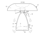
- the collector pulls both ends of the strap 20 and closes the receiving port 16 as shown in FIG. 8 (step ST120).
- the receiving port 16 is in a form that can be closed by a closing member such as a tying string 20 and the receiving portion 14 is formed of an opaque material, immediately after excretion of the stool F, the stool F is taken into the eyes of the collector. Can be touched. Therefore, it is possible to further reduce the chance that the collector feels uncomfortable in the sample collection operation.
- the receiving port 16 since the receiving port 16 is closed, there is also a secondary effect that the smell of the feces F is reduced.
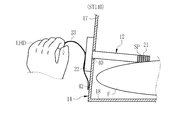
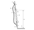
- the collector After the closure of the receiving port 16, the collector removes the stool receptacle 11 from the toilet 45. Then, as shown in FIG. 9, the stool receiver 11 is lightly shaken up and down, left and right so that the vicinity of the receiving port 16 is held with one hand (here, the right hand RHD) and the specimen SP is securely attached to the attaching portion 21 (step ST130). .
- the collector After lightly shaking the stool receiver 11, the collector holds the cover 23 from the receiving part 14 with the left hand LHD, which is the other hand, with the right hand RHD in the vicinity of the receiving port 16, as shown in FIG. Peel off (step ST140).
- the sampler grasps the exposed gripping part 22 with the left hand LHD, and pulls out the sampling tool 12 with the specimen SP attached to the attachment part 21 from the insertion hole 40 (step ST150). ).
- the collector mostly looks at the stool F from the excretion of the stool F in step ST110 to the removal of the sampling tool 12 with the sample SP attached to the attachment part 21 from the receiving part 14 in step ST150. Can be done without putting in.
- the insertion hole 40 is closed by the cover 23 until the cover 23 is peeled from the receiving portion 14 in step ST140, the stool F does not leak from the insertion hole 40.
- the collector removes the disposable cap 26 from the sample container 13 and discards the removed disposable cap 26 (step ST160).
- the rod-shaped portion that is at least a part of the collection tool 12 is accommodated in the sample container 13 through the exposed opening 25, and the opening 25 is opened by the grip portion 22 instead of the disposable cap 26 as shown in FIG. 12B. Is sealed (step ST170).
- the collector discards the stool receiver 11 by flowing the stool receiver 11 into the water of the stool F and the toilet 45 (step ST180).
- the gripping part of the collection tool does not function as a cap for the sample container, open the cap with the sample container to expose the opening, put the collection tool into the sample container through the opening, and finally close the cap Three work steps were required.
- the operation of housing the collection tool 12 in the sample container 13 includes the removal of the disposable cap 26 in step ST160 and the collection tool in step ST170. It only takes two steps of 12 accommodations. Therefore, the sample collection operation can be further simplified.
- the specimen container 13 in which the collection tool 12 is accommodated is set in an inspection apparatus (not shown) and is used for a fecal occult blood test. Note that some of the steps ST100 to ST180 shown in FIG. Specifically, after the stool receiver 11 is discarded for each stool F (step ST180), the sampling tool 12 may be accommodated in the sample container 13 (step ST170). In addition, the disposable cap 26 may be removed from the sample container 13 and discarded (step ST160) before the stool receiver 11 is removed from the toilet bowl 45 (step ST130).
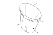
- the receiving part 50 shown in FIGS. 13 and 14 is provided with a bag-like string passing part 53 so as to surround the outer peripheral surface of the side part 52 immediately below the receiving port 51, and the tied string 54 is passed through the string passing part 53. Is. A binding string 54 tied around the bag 51 may be used as a closing member.
- illustration of the mounting portion and the like is omitted to avoid complication.
- the closing member is not limited to the tying string 20 sewn around the receiving port 16 shown in FIG. 1 and the like, and the tying cord 54 tied to the bag around the receiving port 51 shown in FIGS. Any material can be used as long as it can close the receiving port.
- a clip, a fastener (also called a zipper or a chuck), or the like may be used as the closing member.
- a closing member such as a tied string is not essential. Any form that can close the receiving port may be used.
- the collector may grasp the both ends of the mounting portion 15, overlap the ends, and then close the receptacle by twisting the vicinity of the receptacle.
- the collection tool is configured by a main body that has an attachment portion and is held by the receiving portion, and a collection body that has a gripping portion and collects the main body from the receiving portion. .
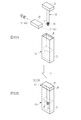
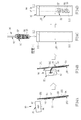
- a collecting tool 60 of the second embodiment shown in FIGS. 15 to 19 includes a plate 61 as a main body and a collection body 62 that is coupled to the plate 61 and collects the plate 61.
- FIG. 15 shows a state before the plate 61 and the recovery body 62 are coupled
- FIG. 16 shows a state where the plate 61 and the recovery body 62 are coupled.
- the plate 61 is made of plastic, for example, and has rigidity.
- An adhesion portion 63 is formed on one surface of the plate 61.
- the attaching part 63 has an uneven shape in which a plurality of mountain-shaped protrusions are formed, and the specimen SP is easily attached as in the attaching part 21 of the first embodiment.
- the recovery body 62 is made of plastic like the plate 61.
- the collection body 62 includes a coupling portion 64 that couples with the plate 61.
- the coupling portion 64 is a space surrounded by a substrate 65 having the same size as the plate 61 and two elongated holding arms 66.
- the substrate 65 is in contact with the surface of the plate 61 opposite to the surface on which the adhesion portion 63 is formed in the state of FIG. 16 where the plate 61 and the coupling portion 64 are coupled.
- the holding arm 66 is provided so as to avoid the adhering portion 63, and its tip is pointed like a wedge.
- the holding arm 66 will be described in detail with reference to FIG.
- illustration is abbreviate
- a drop-off prevention mechanism such as a click mechanism is provided.
- a grip portion 67 that is gripped by the harvester is formed.
- the grip part 67 has a rectangular parallelepiped shape as the grip part 22 of the first embodiment.
- the grip portion 67 functions as a cap that seals the opening 82 of the sample container 80, as in the grip portion 22 of the first embodiment (see FIG. 19). For this reason, as in the first embodiment, it is possible to further simplify the sample collection operation.
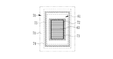
- the receiving portion 70 of the second embodiment has an exposure opening 72 formed on the side portion 71 thereof.
- the plate 61 is detachably attached to the outer peripheral surface of the side portion 71 with an adhesive 73 (shown by hatching) so that the adhering portion 63 is exposed in the receiving portion 70 through the exposing opening 72. In other words, the exposure opening 72 is blocked by the plate 61 itself.
- this adhesive 73 at least a part of the sampling tool 60 including the attaching portion 63, that is, the plate 61 is held integrally and detachably in the receiving portion 70 in a state where the attaching portion 63 is disposed in the receiving portion 70. Has been. Further, the adhesive 73 creates a gap between the plate 61 and the outer peripheral surface of the side portion 71.
- the plate 61 is exposed outside the receiving portion 70 on the outer peripheral surface of the side portion 71 of the receiving portion 70.
- the exposed portion of the plate 61 is covered with a peelable rectangular cover 74, like the grip portion 22 of the first embodiment.
- the cover 74 is detachably attached to the outer peripheral surface of the side portion 71 of the receiving portion 70 by an adhesive 75 (indicated by hatching).
- the cover 74 covers the plate 61 exposed to the outside of the receiving portion 70 from the exposure opening 72, and closes the exposure opening 72 in an airtight and liquid-tight manner. Note that the cover 74 may not be provided as long as the exposure opening 72 is sufficiently airtight and liquid-tightly covered with the plate 61 by the adhesive 73.
- the exposure opening 72 from the inner peripheral surface of the bottom portion 76 of the receiving portion 70 (the exposure at the highest position).
- the height H2 of the end 72A) of the opening 72 is 3 cm or less. That is, the exposure opening 72 is formed in the side portion 71 of the receiving portion 70 at a height of 3 cm or less from the inner peripheral surface of the bottom portion 76 of the receiving portion 70.
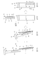
- FIG. 19 is a state diagram excerpting the sample SP collection procedure of the second embodiment. Also in the second embodiment, the procedure from step ST100 to step ST140 in FIG. 4 of the first embodiment is the same. For this reason, FIG. 19 shows the state of FIG. 19A in which the cover 74 is peeled off from the receiving part 70 and the surface on the opposite side to the surface where the adhering part 63 of the plate 61 is formed is exposed.
- the sampler inserts the tip of the holding arm 66 of the coupling portion 64 of the collection body 62 into the gap between the plate 61 and the outer peripheral surface of the side portion 71 made of the adhesive 73. .
- the collector moves the collection body 62 downward while tilting the collection body 62 to the opposite side of the receiving portion 70.
- the plate 61 is peeled from the outer peripheral surface of the side portion 71 and the plate 61 and the coupling portion 64 are coupled.
- one hand of the collector has the vicinity of the receiving port of the receiving portion 70, the cover 74 is peeled off by the other hand, and the collection body 62 is operated to collect the plate 61.
- a diluent 81 is stored in the specimen container 80 of the second embodiment, as in the specimen container 13 of the first embodiment.
- the sample container 80 has an opening 82 for receiving the collection tool 60, and the opening 82 is covered with a disposable cap 83 before the collection tool 60 is accommodated.
- the collector removes the disposable cap 83 from the sample container 80 and discards it.
- the opening 82 is sealed with the grip portion 67 instead of the disposable cap 83.
- the adhering portion 63 is formed on one surface of the plate 61, so that the area of the adhering portion 63 can be made relatively larger than that of the rod-shaped collection tool 12 of the first embodiment. . Therefore, the amount of sample SP collected can be increased.
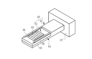
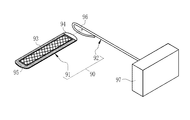
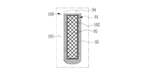
- a collecting tool 90 according to the third embodiment shown in FIGS. 20 to 24 includes a tape 91 as a main body and a collecting body 92 that engages with the tape 91 and collects the tape 91.
- FIG. 20 shows a state before the tape 91 is wound around the collecting body 92
- FIG. 21 shows a state where the tape 91 is wound around the collecting body 92.
- the tape 91 is, for example, waterproof paper, cloth, or a plastic film, and has flexibility.
- An adhesion portion 93 is formed on one surface of the tape 91.
- the adhering portion 93 has a mesh shape, and the specimen SP is easily adhering to the adhering portion 21 in the first embodiment and the adhering portion 63 in the second embodiment.
- An adhesive 95 (shown by hatching) is applied to the surface of the tape 91 where the adhering portion 93 is formed, except for one end 94. That is, the tape 91 has a structure like an adhesive bandage in which a pad is arranged at the center and the periphery is an adhesive layer.
- the collection body 92 is made of plastic, for example.
- the collection body 92 has an engaging portion 96 that engages with one end 94 of the tape 91.
- the engaging portion 96 is a substantially elliptical ring formed by bending the tip of a wire-like bar.
- the tape 91 is wound around the engaging portion 96 with the attachment portion 93 facing the front side and the position being shifted little by little.
- illustration is omitted, in order to fix the other end to the recovery body 92 on the surface opposite to the surface on which the adhering portion 93 is formed at the other end opposite to the one end 94 that is the winding end portion. An adhesive or the like is applied.
- a grip portion 97 that is gripped by the collector is formed.
- the grip portion 97 has a rectangular parallelepiped shape, similar to the grip portion 22 of the first embodiment and the grip portion 67 of the second embodiment. Further, the grip portion 97 functions as a cap that seals the opening 112 of the sample container 110, as in the grip portion 22 of the first embodiment and the grip portion 67 of the second embodiment (see FIG. 24). For this reason, as in the first and second embodiments, the sample collection operation can be further simplified.
- the receiving portion 100 of the second embodiment has an exposure opening 102 formed on the side portion 101 thereof.
- the tape 91 is detachably attached to the outer peripheral surface of the side portion 101 with an adhesive 95 so that the one end 94 is upward and the adhering portion 93 is exposed in the receiving portion 100 through the exposure opening 102. ing. That is, the tape 91 closes the exposure opening 102 in an airtight and liquid tight manner.
- at least a part of the sampling tool 90 including the attaching portion 93, that is, the tape 91 is integrally and detachably held by the receiving portion 100 in a state where the attaching portion 93 is disposed in the receiving portion 100.
- FIG. 24 is a state diagram excerpting the sample SP collection procedure of the third embodiment.
- the procedure from step ST100 to step ST140 in FIG. 4 of the first embodiment is the same.
- the procedure from step ST100 to step ST130 is the same.
- the step ST140 for peeling the covers 23 and 74 from the receiving portions 14 and 70 is omitted. For this reason, in FIG. 24, the one end 94 of the tape 91 is shown from the state of FIG.
- the collector engages one end 94 of the tape 91 with the engaging portion 96 of the collection body 92. Since the adhesive 95 is not applied to the one end 94, it can be easily drawn and can be easily engaged with the engaging portion 96.
- the collector sequentially moves the collection body 92 in the direction perpendicular to the paper surface while rotating the collection body 92 in the clockwise direction when viewed from the grip portion 97 side.
- the tape 91 is wound around the engaging portion 96 with its position gradually shifted with the adhering portion 93 as the front side.
- the harvester fixes the other end opposite to the end 94, which is the end of the winding, to the collection body 92 so that the wound tape 91 is not unwound.
- one hand of the collector has the vicinity of the receiving port of the receiving unit 100, and the collecting body 92 is operated with the other hand, and the tape 91 is collected.
- the diluent 111 is stored in the same manner as the sample container 13 according to the first embodiment and the sample container 80 according to the second embodiment.
- the sample container 110 has an opening 112 for receiving the collection tool 90, and the opening 112 is covered with a disposable cap 113 before the collection tool 90 is accommodated.
- the collector removes the disposable cap 113 from the sample container 110 and discards it.
- most of the tape 91 and the collection body 92 of the collection tool 90 are accommodated in the sample container 110 through the exposed opening 112.
- the opening 112 is sealed with the grip portion 97 instead of the disposable cap 113.
- illustration of the adhesive 95 is omitted.
- the covers 23 and 74 of the second and third embodiments are not necessary. For this reason, the number of parts can be reduced, and the manufacturing cost can be reduced. Further, since the work for peeling off the covers 23 and 74 from the receiving portions 14 and 70 is not required, the sample collection work can be further simplified.
- the tape 91 can take a relatively large area of the adhering portion 93 and increases the collection amount of the specimen SP compared to the rod-shaped collection tool 12 of the first embodiment. be able to.
- the adhering portion may have a brush shape in addition to the uneven shape and mesh shape of each of the above embodiments.
- the adhering portion may be formed of a material that easily attaches the specimen SP, or may be coated with a material that easily attaches the specimen SP. As a material to which the specimen SP is likely to adhere, a material having appropriate adhesiveness can be considered.
- the insertion hole 40 of the first embodiment and the exposure openings 72 and 102 of the second and third embodiments are all formed in the side parts 17, 71 and 101 of the receiving parts 14, 70 and 100. You may form these in the bottom parts 18,76,103.
- the adhesives 42 and 75 of the covers 23 and 74 are not necessarily applied in a ring shape. For example, it may be applied only to the upper and lower portions of the covers 23 and 74.
- the receiving part may be formed of a translucent material colored in green. Or although it is a transparent material like a bubble buffer material, you may form a receiving part with the material which the visual field to the inside is interrupted
Landscapes
- Health & Medical Sciences (AREA)
- Life Sciences & Earth Sciences (AREA)
- Chemical & Material Sciences (AREA)
- Immunology (AREA)
- Analytical Chemistry (AREA)
- Biochemistry (AREA)
- General Health & Medical Sciences (AREA)
- General Physics & Mathematics (AREA)
- Physics & Mathematics (AREA)
- Pathology (AREA)
- Engineering & Computer Science (AREA)
- Biomedical Technology (AREA)
- Hematology (AREA)
- Molecular Biology (AREA)
- Urology & Nephrology (AREA)
- Food Science & Technology (AREA)
- Medicinal Chemistry (AREA)
- Investigating Or Analysing Biological Materials (AREA)
- Sampling And Sample Adjustment (AREA)
Abstract
L'invention concerne un kit collecteur d'échantillon qui permet de réduire les risques d'expériences désagréables sur la partie d'un collecteur d'échantillon pendant un travail de collecte d'échantillon. Dans ce kit collecteur d'échantillon (10), une partie en forme de tige d'un outil de collecte (12) qui comprend une partie de fixation (21) à laquelle est fixée une partie des selles (F) sous la forme d'un échantillon (SP), est maintenue d'un seul tenant et amovible sur une partie de réception (14) pour recevoir les selles (F) dans un outil de réception de selles (11). La partie de réception (14) est constituée d'un matériau opaque. En outre, un orifice de réception (16) dans lequel passent les selles (F) pour être réceptionnées, est conçu pour pouvoir être fermé par un cordon (20).
Priority Applications (1)
| Application Number | Priority Date | Filing Date | Title |
|---|---|---|---|
| JP2020505612A JP7011038B2 (ja) | 2018-03-14 | 2019-01-10 | 検体採取キット |
Applications Claiming Priority (2)
| Application Number | Priority Date | Filing Date | Title |
|---|---|---|---|
| JP2018-046304 | 2018-03-14 | ||
| JP2018046304 | 2018-03-14 |
Publications (1)
| Publication Number | Publication Date |
|---|---|
| WO2019176251A1 true WO2019176251A1 (fr) | 2019-09-19 |
Family
ID=67907149
Family Applications (1)
| Application Number | Title | Priority Date | Filing Date |
|---|---|---|---|
| PCT/JP2019/000506 Ceased WO2019176251A1 (fr) | 2018-03-14 | 2019-01-10 | Kit collecteur d'échantillon |
Country Status (2)
| Country | Link |
|---|---|
| JP (1) | JP7011038B2 (fr) |
| WO (1) | WO2019176251A1 (fr) |
Cited By (2)
| Publication number | Priority date | Publication date | Assignee | Title |
|---|---|---|---|---|
| CN116224424A (zh) * | 2023-02-28 | 2023-06-06 | 天津大学 | 一种光释光试验一体化采样箱 |
| CN116782832A (zh) * | 2021-01-20 | 2023-09-19 | 生物生命科学股份有限公司 | 样本采集用试剂盒 |
Citations (8)
| Publication number | Priority date | Publication date | Assignee | Title |
|---|---|---|---|---|
| JPS61102941U (fr) * | 1984-12-13 | 1986-07-01 | ||
| JPH06148178A (ja) * | 1990-12-07 | 1994-05-27 | Soda Nikka Kk | 検査用生体試料採取容器 |
| JPH10197525A (ja) * | 1997-01-09 | 1998-07-31 | Matsushita Electric Ind Co Ltd | 採便装置 |
| JP2004212368A (ja) * | 2003-01-04 | 2004-07-29 | Aoki Ryutsu Kk | 検体採取用具 |
| JP2011059052A (ja) * | 2009-09-14 | 2011-03-24 | Arkray Inc | 採取用具及び採取方法 |
| WO2014146665A1 (fr) * | 2013-03-22 | 2014-09-25 | Oceansandbox Aps | Unité de collecte pour un échantillon de selles |
| WO2016143272A1 (fr) * | 2015-03-09 | 2016-09-15 | 協和メデックス株式会社 | Échantillonneur de selles |
| JP2017198512A (ja) * | 2016-03-12 | 2017-11-02 | 株式会社▲高▼橋型精 | 採便具 |
-
2019
- 2019-01-10 WO PCT/JP2019/000506 patent/WO2019176251A1/fr not_active Ceased
- 2019-01-10 JP JP2020505612A patent/JP7011038B2/ja active Active
Patent Citations (8)
| Publication number | Priority date | Publication date | Assignee | Title |
|---|---|---|---|---|
| JPS61102941U (fr) * | 1984-12-13 | 1986-07-01 | ||
| JPH06148178A (ja) * | 1990-12-07 | 1994-05-27 | Soda Nikka Kk | 検査用生体試料採取容器 |
| JPH10197525A (ja) * | 1997-01-09 | 1998-07-31 | Matsushita Electric Ind Co Ltd | 採便装置 |
| JP2004212368A (ja) * | 2003-01-04 | 2004-07-29 | Aoki Ryutsu Kk | 検体採取用具 |
| JP2011059052A (ja) * | 2009-09-14 | 2011-03-24 | Arkray Inc | 採取用具及び採取方法 |
| WO2014146665A1 (fr) * | 2013-03-22 | 2014-09-25 | Oceansandbox Aps | Unité de collecte pour un échantillon de selles |
| WO2016143272A1 (fr) * | 2015-03-09 | 2016-09-15 | 協和メデックス株式会社 | Échantillonneur de selles |
| JP2017198512A (ja) * | 2016-03-12 | 2017-11-02 | 株式会社▲高▼橋型精 | 採便具 |
Cited By (2)
| Publication number | Priority date | Publication date | Assignee | Title |
|---|---|---|---|---|
| CN116782832A (zh) * | 2021-01-20 | 2023-09-19 | 生物生命科学股份有限公司 | 样本采集用试剂盒 |
| CN116224424A (zh) * | 2023-02-28 | 2023-06-06 | 天津大学 | 一种光释光试验一体化采样箱 |
Also Published As
| Publication number | Publication date |
|---|---|
| JP7011038B2 (ja) | 2022-01-26 |
| JPWO2019176251A1 (ja) | 2021-03-18 |
Similar Documents
| Publication | Publication Date | Title |
|---|---|---|
| KR890003328B1 (ko) | 의료기기 및 이로부터 연장되는 부속물에 대한 전염성 미생물의 전이방지용 드레이프 장치 | |
| ES2355750T3 (es) | Dispositivo de recogida de fluido oral y método de recogida. | |
| US9610005B2 (en) | Methods, devices and systems for improved hygiene during endoscopic procedures | |
| US5605161A (en) | Disposable urinalysis device with indicator | |
| CA2870936C (fr) | Ensemble catheter intermittent | |
| US5549120A (en) | Apparatus for applying an elastic protective sheath on an elongate bodily membrane, and protective aid article having such an apparatus | |
| CA2523805A1 (fr) | Gaine protectrice pour dispositif d'eclairage d'un speculum vaginal jetable | |
| WO2019176251A1 (fr) | Kit collecteur d'échantillon | |
| US20190091078A1 (en) | Diaper Accessory Attachment | |
| JP2004528570A (ja) | 尿収集装置 | |
| CN213787771U (zh) | 一种多功能的临床医疗手术巾布 | |
| KR20090061707A (ko) | 애완견용 대변 수거장치 | |
| GB2392842A (en) | Urinary device | |
| JP4164038B2 (ja) | 手術用パウチおよびその使用方法 | |
| CN215821561U (zh) | 一种宫腔操作防护套 | |
| JP2006087557A (ja) | 内視鏡スコープ用保護具 | |
| WO2021205440A1 (fr) | Enveloppe de protection jetable et son procédé d'utilisation | |
| US20250152397A1 (en) | Ostomy pouch device and method | |
| CN211213252U (zh) | 一种消化科粪便取样工具 | |
| WO2017075235A1 (fr) | Procédés, dispositifs et systèmes pour l'amélioration de l'hygiène au cours de procédures endoscopiques | |
| JP3237621U (ja) | 糞の受容装置 | |
| JP4185330B2 (ja) | 内視鏡用外套シース着脱スタンド | |
| JP7538307B1 (ja) | 歯磨き用マスク | |
| JP5838071B2 (ja) | 水まわり用手袋 | |
| JP3181847U (ja) | サージカルドレープの受水袋 |
Legal Events
| Date | Code | Title | Description |
|---|---|---|---|
| 121 | Ep: the epo has been informed by wipo that ep was designated in this application |
Ref document number: 19768051 Country of ref document: EP Kind code of ref document: A1 |
|
| ENP | Entry into the national phase |
Ref document number: 2020505612 Country of ref document: JP Kind code of ref document: A |
|
| NENP | Non-entry into the national phase |
Ref country code: DE |
|
| 122 | Ep: pct application non-entry in european phase |
Ref document number: 19768051 Country of ref document: EP Kind code of ref document: A1 |