WO2019176275A1 - Dispositif et système d'évaluation de cellules - Google Patents
Dispositif et système d'évaluation de cellules Download PDFInfo
- Publication number
- WO2019176275A1 WO2019176275A1 PCT/JP2019/001252 JP2019001252W WO2019176275A1 WO 2019176275 A1 WO2019176275 A1 WO 2019176275A1 JP 2019001252 W JP2019001252 W JP 2019001252W WO 2019176275 A1 WO2019176275 A1 WO 2019176275A1
- Authority
- WO
- WIPO (PCT)
- Prior art keywords
- cell
- unit
- capturing
- cell evaluation
- substance
- Prior art date
- Legal status (The legal status is an assumption and is not a legal conclusion. Google has not performed a legal analysis and makes no representation as to the accuracy of the status listed.)
- Ceased
Links
Images


Classifications
-
- C—CHEMISTRY; METALLURGY
- C12—BIOCHEMISTRY; BEER; SPIRITS; WINE; VINEGAR; MICROBIOLOGY; ENZYMOLOGY; MUTATION OR GENETIC ENGINEERING
- C12M—APPARATUS FOR ENZYMOLOGY OR MICROBIOLOGY; APPARATUS FOR CULTURING MICROORGANISMS FOR PRODUCING BIOMASS, FOR GROWING CELLS OR FOR OBTAINING FERMENTATION OR METABOLIC PRODUCTS, i.e. BIOREACTORS OR FERMENTERS
- C12M1/00—Apparatus for enzymology or microbiology
- C12M1/34—Measuring or testing with condition measuring or sensing means, e.g. colony counters
-
- C—CHEMISTRY; METALLURGY
- C12—BIOCHEMISTRY; BEER; SPIRITS; WINE; VINEGAR; MICROBIOLOGY; ENZYMOLOGY; MUTATION OR GENETIC ENGINEERING
- C12M—APPARATUS FOR ENZYMOLOGY OR MICROBIOLOGY; APPARATUS FOR CULTURING MICROORGANISMS FOR PRODUCING BIOMASS, FOR GROWING CELLS OR FOR OBTAINING FERMENTATION OR METABOLIC PRODUCTS, i.e. BIOREACTORS OR FERMENTERS
- C12M41/00—Means for regulation, monitoring, measurement or control, e.g. flow regulation
- C12M41/30—Means for regulation, monitoring, measurement or control, e.g. flow regulation of concentration
- C12M41/36—Means for regulation, monitoring, measurement or control, e.g. flow regulation of concentration of biomass, e.g. colony counters or by turbidity measurements
-
- C—CHEMISTRY; METALLURGY
- C12—BIOCHEMISTRY; BEER; SPIRITS; WINE; VINEGAR; MICROBIOLOGY; ENZYMOLOGY; MUTATION OR GENETIC ENGINEERING
- C12M—APPARATUS FOR ENZYMOLOGY OR MICROBIOLOGY; APPARATUS FOR CULTURING MICROORGANISMS FOR PRODUCING BIOMASS, FOR GROWING CELLS OR FOR OBTAINING FERMENTATION OR METABOLIC PRODUCTS, i.e. BIOREACTORS OR FERMENTERS
- C12M41/00—Means for regulation, monitoring, measurement or control, e.g. flow regulation
- C12M41/46—Means for regulation, monitoring, measurement or control, e.g. flow regulation of cellular or enzymatic activity or functionality, e.g. cell viability
-
- G—PHYSICS
- G01—MEASURING; TESTING
- G01N—INVESTIGATING OR ANALYSING MATERIALS BY DETERMINING THEIR CHEMICAL OR PHYSICAL PROPERTIES
- G01N21/00—Investigating or analysing materials by the use of optical means, i.e. using sub-millimetre waves, infrared, visible or ultraviolet light
- G01N21/75—Systems in which material is subjected to a chemical reaction, the progress or the result of the reaction being investigated
- G01N21/76—Chemiluminescence; Bioluminescence
-
- G—PHYSICS
- G01—MEASURING; TESTING
- G01N—INVESTIGATING OR ANALYSING MATERIALS BY DETERMINING THEIR CHEMICAL OR PHYSICAL PROPERTIES
- G01N33/00—Investigating or analysing materials by specific methods not covered by groups G01N1/00 - G01N31/00
- G01N33/48—Biological material, e.g. blood, urine; Haemocytometers
-
- G—PHYSICS
- G01—MEASURING; TESTING
- G01N—INVESTIGATING OR ANALYSING MATERIALS BY DETERMINING THEIR CHEMICAL OR PHYSICAL PROPERTIES
- G01N33/00—Investigating or analysing materials by specific methods not covered by groups G01N1/00 - G01N31/00
- G01N33/48—Biological material, e.g. blood, urine; Haemocytometers
- G01N33/50—Chemical analysis of biological material, e.g. blood, urine; Testing involving biospecific ligand binding methods; Immunological testing
- G01N33/53—Immunoassay; Biospecific binding assay; Materials therefor
Definitions
- This technology relates to a cell evaluation device and a cell evaluation system.
- CMOS Complementary Metal Oxide Semiconductor
- the present technology has been made in view of such a situation, and a main object thereof is to provide a cell evaluation apparatus that can accurately and accurately evaluate cells and secretory substances emitted from the cells. To do.
- the present inventor has surprisingly succeeded in accurately and accurately evaluating cells and secretory substances emitted from the cells.
- the technology has been completed.
- a first capturing unit that captures a secretory substance secreted by a cell
- An image acquisition unit for acquiring an image obtained by imaging the light emitted from the luminescent substance combined with the observation light of the cell and the secretory substance,
- the image acquisition unit and the first capturing unit are arranged in this order,
- a cell evaluation device is provided in which the image acquisition unit acquires positional information of the cell and the secretory substance.
- the image acquisition unit may be a CMOS image sensor.
- the image acquisition unit can acquire an image obtained by imaging chemiluminescence generated by the reaction of the luminescent substance, which is an enzyme, with a substrate.
- the first capturing unit may include a molecule that binds non-specifically or specifically to the secretory substance.
- a protection unit may be disposed in a region that does not include the molecule in which the first capturing unit binds nonspecifically or specifically to the secretory substance.
- the molecule that nonspecifically or specifically binds to the secretory substance may be at least one selected from the group consisting of a first antibody, a first aptamer, and a molecular imprint polymer, and there are a plurality of the first antibodies.
- a first antibody a first aptamer, and a molecular imprint polymer, and there are a plurality of the first antibodies.
- OK is OK.
- the cell evaluation device further includes a second capturing unit that captures the cells.
- the image acquisition unit and the second capturing unit are arranged in this order. May be.
- the first capturing unit may be arranged around the second capturing unit.
- the second capturing unit may include a molecule that binds nonspecifically or specifically to the cell.
- a protection unit may be disposed in a region that does not include the molecule in which the second capturing unit binds nonspecifically or specifically to the cell.
- the molecule that nonspecifically or specifically binds to the cell may be at least one selected from the group consisting of a second antibody, a second aptamer, a supramolecule, and oleylamine, and the second antibody may be a plurality of types. Good.
- a photodegradable linker may be included between the second capturing unit and the image acquiring unit.
- a first capturing unit that captures a secretory substance secreted by the cell
- An image acquisition unit for acquiring an image obtained by imaging the light emitted from a light-emitting substance combined with the observation light of the cell and the secretory substance
- An analysis unit for analyzing the obtained image
- the image acquisition unit and the first capturing unit are arranged in this order,
- a cell evaluation device is provided in which the image acquisition unit acquires positional information of the cell and the secretory substance.
- the analysis unit can perform the quantification of the secretory substance based on the intensity of the light emitted from the luminescent substance combined with the secretory substance.
- the analysis unit can analyze the cell based on luminance information of light emitted from a light-emitting substance combined with the observation light and / or secretory substance of the cell.
- the cell evaluation apparatus may further include an irradiation unit that projects the cells.
- the cell evaluation apparatus may further include a display unit that displays the image.
- a display unit that displays the image.
- Well image display based on a cell image obtained by imaging the observation light of the cell and a chemiluminescence image obtained by imaging light emitted from a luminescent substance combined with the secretory substance
- an analysis data display unit and an analysis plot display unit based on the analysis of the analysis unit.
- a first capturing unit that captures a secretory substance secreted by a cell
- An image acquisition unit for acquiring an image obtained by imaging the light emitted from a light-emitting substance combined with the observation light of the cell and the secretory substance
- An analysis unit for analyzing the obtained image
- the image acquisition unit and the first capturing unit are arranged in this order,
- a cell evaluation system is provided in which the image acquisition unit acquires positional information of the cell and the secretory substance.
- the CMOS image sensor provides a cell evaluation apparatus that acquires positional information between the cell and the secretory substance, A first antibody that captures secretory material secreted by the cell; A second antibody that captures cells; A CMOS image sensor for obtaining an image obtained by imaging the light emitted from a light-emitting substance combined with the observation light of the cell and the secretory substance; An analysis unit for analyzing the acquired image, The CMOS image sensor, the first antibody and the second antibody are arranged in this order, The first antibody is disposed around the second antibody;
- cells and secretory substances emitted from the cells can be accurately evaluated with high accuracy.
- the effects described here are not necessarily limited, and may be any of the effects described in the present disclosure.
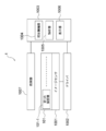
- FIG. 1 is a block diagram illustrating a configuration example of the cell evaluation device according to the first embodiment to which the present technology is applied.
- FIG. 2 is a diagram illustrating a configuration example of the cell evaluation device according to the first embodiment to which the present technology is applied.
- FIG. 3 is a diagram illustrating a configuration example of the cell evaluation device according to the first embodiment to which the present technology is applied.
- FIG. 4 is a cross-sectional view illustrating a configuration example of a CMOS image sensor (solid-state imaging device) including an antibody layer.
- FIG. 5 is a diagram illustrating a configuration example of the analysis unit.
- FIG. 6 is a diagram illustrating a configuration example of the display unit.
- FIG. 1 is a block diagram illustrating a configuration example of the cell evaluation device according to the first embodiment to which the present technology is applied.
- FIG. 2 is a diagram illustrating a configuration example of the cell evaluation device according to the first embodiment to which the present technology is applied.
- FIG. 3 is a diagram
- FIG. 7 is a block diagram illustrating a configuration example of the cell evaluation device according to the second embodiment to which the present technology is applied.
- FIG. 8 is a diagram illustrating an example of patterning of the first capturing unit and the second capturing unit.
- FIG. 9 is a diagram illustrating an example of patterning of the first capturing unit and the second capturing unit.
- FIG. 10 is a diagram illustrating an example of patterning of the first capturing unit and the second capturing unit.
- the ELISPOT method cultivates a large amount of cells in a well, captures the secretory substance of the cell with a membrane placed at the bottom of the well, removes the cell, reacts with the secretory substance attached to the membrane, and colors the The number of secreted cells can be calculated by counting the number by microscopic observation.
- a method of measuring in a small well for each single cell has been proposed, but since individual cells are divided into wells, it is not possible to observe the interaction in the coexistence of multiple cells.
- the ELISPOT method needs to remove cells before measurement as described above, it is impossible to take out specific cells after ELISPOT and perform post-analysis (eg, gene analysis).
- This technology has been made in view of the above situation, and it is possible to know which cell has secreted what amount in an environment where a plurality of cells coexist. Eventually, it becomes possible to grasp the interaction occurring between different cells such as cancer cells and immune cells, which have been difficult as applications.
- Examples of cells observed by the cell evaluation apparatus according to the present technology include cancer cells, immune cells, and the like.
- immune cells include T cells, NK cells, macrophages, and the like.
- cells include tissues in which single or multiple cells are assembled with a certain function.
- cell secretions observed by the cell evaluation apparatus according to the present technology include IFN- ⁇ , interleukin, chemokine and the like.
- this technique can add at least quantification of secreted substances and cell imaging for each cell to the function of ELISPOT (counting secretory cells), it is possible to specify the cell type and state of the secreted substance. . For example, in co-culture of cancer cells and immune cells, it is currently unknown whether IFN ⁇ was produced, or only the live cells that produced IFN ⁇ were counted, but IFN ⁇ was also produced during apoptosis. can do. Since this technique has a technique based on at least the ELISPOT method and the ELISA method, a necessary blood sample can be reduced. Since cells can be collected in principle, it is possible to reanalyze only those cells that have released secretory substances. It is possible to evaluate which cell has secreted how much in an environment where a plurality of cells coexist. That is, as described above, it is possible to grasp the interaction occurring between different cells such as cancer cells and immune cells, which has been difficult until now.
- Example 1 the first embodiment
- the second embodiment Cell evaluation device
- Example 2 the third embodiment (example of cell evaluation system)
- the cell evaluation apparatus includes a first capturing unit that captures a secretory substance secreted by a cell, light emitted from the observation light of the cell and the secretory substance
- An image acquisition unit that acquires an image obtained by imaging light emitted from a substance, wherein the image acquisition unit and the first capture unit are arranged in this order, and the image acquisition unit is secreted from the cell
- It is a cell evaluation apparatus which acquires positional information with a substance.
- the image acquisition unit and the first acquisition unit are arranged in this order, the image acquisition unit and the first acquisition unit may be arranged continuously, or the image acquisition unit and the first acquisition unit It means that the capturing part may be arranged via an optional material layer (which may be a material film, the same applies hereinafter) or a material part. And that the image acquisition unit and the first acquisition unit are continuously arranged means that the first acquisition unit is arranged immediately above the image acquisition unit.
- the fact that the first capturing unit is disposed immediately above the image acquiring unit means that the first capturing unit is disposed at a distance within 150 ⁇ m, preferably within 10 ⁇ m, from the image acquiring unit, for example. To do.
- the cell evaluation device may further include at least one of an analysis unit, an irradiation unit, and a display unit. That is, the cell evaluation apparatus according to the first embodiment of the present technology can further include an analysis unit, an irradiation unit, a display unit, and an analysis unit and irradiation. A display section, an analysis section and a display section, an irradiation section and a display section, and an analysis section, an irradiation section and a display section. it can.
- FIG. 1 is a block diagram illustrating an example of the cell evaluation apparatus according to the first embodiment of the present technology.
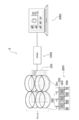
- FIG.2 and FIG.3 is a block diagram which shows an example of the cell evaluation apparatus of 1st Embodiment which concerns on this technique.
- the cell evaluation apparatus 1 includes at least an upper part 101 of an image sensor including a first capturing unit 101, an image sensor 1001 (for example, a CMOS image sensor) that is an image acquisition unit, and an analysis unit 1005.
- the cell evaluation apparatus 1 further includes a driver 1002, an irradiation control unit 1004, a display unit 1006, and an irradiation unit 1007.
- the irradiation control unit 1004, the analysis unit 1005, and the display unit 1006 may be formed as one device 1003.
- the upper part 101 of the image sensor may include a protective part in addition to the first capturing part 101.
- the irradiation control unit 1004 can control the wavelength selectivity (selectivity of light color) of light emitted by the irradiation unit 1007 and the light exposure time.
- the first capturing unit 101-1 (for example, the capturing unit including the first antibody for supplementing secretory substance) is disposed on the image sensor 1001 in a desired positional relationship.
- the cell can be identified by taking a cell image using the cell observation light or the irradiation unit 1007 and analyzing the cell size and cell shape. It is possible to accurately grasp the cell type and cell state (cell viability, etc.).
- Digital ⁇ Mirror Device (DMD) or the like is included in the irradiation unit, and the irradiation position can be controlled.
- DMD Digital ⁇ Mirror Device
- the secretory substance emitted from the cells is captured by the first capturing unit 101-1 (for example, the capturing unit including the first antibody for capturing the secretory substance). Furthermore, by making it react with a chemiluminescent substance etc., weak light can be generated and the light can be acquired with the image sensor 1001 directly under.
- the chemiluminescent substance is, for example, an enzyme, and chemiluminescence is emitted by the reaction of the enzyme with the substrate.
- the position where the secretory substance is obtained on the image sensor 1001 can be mapped. Since the positional relationship between the first capture unit 101-1 (for example, the capture unit including the first antibody for capturing the secretory substance) and the cell can be designated in advance, the cell that has released the secretory substance is also specified. Is possible.
- the analysis unit 1005 can also quantify the secretory substance by utilizing the fact that the luminance changes depending on the concentration of the secretory substance. An image obtained from the image sensor 1001 is displayed on the display unit 1006 (for example, a monitor) through the analysis unit 1005.
- the density of the first antibody for capturing the secretory substance contained in the first capturing unit 101-1 is increased, or the image sensor 1001 and the first capturing unit 101-1 (for example, the antibody)
- There are measures such as making the distance to the layer as short as possible (arranging it directly above the image sensor 1001), increasing the exposure time, and separating the background noise portion and the signal portion by image processing.
- Cell image acquisition and secretory substance detection can also be performed in real time on the image sensor 1001.
- the cell evaluation apparatus 2 includes an antibody layer (first capture unit) 201 including an antibody (first antibody) 200, a CMOS image sensor 2001 that is an image acquisition unit, a driver (driver) 2002, an analysis unit, and a display And a device 2003 including a unit.
- the CMOS image sensor 2001 shows three pixels.
- the CMOS image sensor 2001 includes a protective layer 202, a semiconductor substrate 203, and a wiring layer 204 in order from the light incident side.
- a photodiode (PD) (three photodiodes (PD) in FIG. 2) is formed on the semiconductor substrate 203.
- An antibody layer 201 is disposed immediately above the protective layer 202 (in the upward direction of the protective layer in FIG. 2).
- the antibody layer 201 is disposed immediately above the protective layer 202, so that the light emitted by the luminescent substance combined with the secreted substance captured by the antibody 200 contained in the antibody layer 201 and the observation light of the cell can be converted into a CMOS image.
- the sensor 2001 can receive light efficiently.
- the cell observation light means light obtained by, for example, projecting natural light or room light onto a cell.
- FIG. 2 four wells (two in the horizontal direction and two in the vertical direction in FIG. 2) are shown. However, in the cell evaluation apparatus 2, one well has one well. It means to be disposed immediately above the CMOS image sensor 2001 (the protective layer 205 included in the CMOS image sensor 2001). In the well, for example, an antibody 200 that captures a secreted substance is immobilized in a collagen (Collagen) coat (protection part), traps the pretreated cells, gives the cells stimulation, and is cultured. The secretory substance is emitted from the cell, and the secretory substance is captured by the antibody 200.
- a collagen Collagen
- the cell evaluation apparatus 3 includes an antibody layer (first capturing unit) 301 including an antibody 300, a CMOS image sensor 3001 that is an image acquisition unit, a driver (driver) 3002, an analysis unit, and a display unit. And an irradiation unit 3004.
- the CMOS image sensor 3001 shows three pixels.
- the CMOS image sensor 3001 includes a protective layer 302, a semiconductor substrate 303, and a wiring layer 304 in order from the light incident side.
- a photodiode (PD) (three photodiodes (PD) in FIG. 3) is formed on the semiconductor substrate 303.
- An antibody layer 301 is disposed immediately above the protective layer 302 (upward of the protective layer in FIG. 3). By disposing the antibody layer 301 immediately above the protective layer 302, the light emitted by the luminescent substance combined with the secreted substance captured by the antibody 300 contained in the antibody layer 301 and the irradiation unit 3004 project onto the cell.
- the CMOS image sensor 3001 can efficiently receive the light obtained by this.
- CMOS complementary metal-oxide-semiconductor
- the image sensor 3001 is disposed directly above the protective layer 305. That is, in the cell evaluation device 3, at least four CMOS image sensors 3001 are required.
- an antibody 300 that captures a secretory substance is immobilized on a collagen (Collagen) coat (protection part), traps the pretreated cells, gives the cells stimulation, and is cultured. Secreted substances are emitted from the cells, and the secreted substances are captured by the antibody 300.
- the cell evaluation device includes a first capturing unit.
- the first capturing unit captures secretory substances secreted by the cells.
- the first capture portion can include a molecule that binds non-specifically or specifically to the secretory substance.
- the molecule that nonspecifically or specifically binds to the secretory substance may be at least one selected from the group of the first antibody, the first aptamer, and the imprint polymer, and the first antibody may be plural types.
- a protective part can be arranged in a region where the first capturing part does not contain a molecule that nonspecifically or specifically binds to the secretory substance.
- the protection unit may be formed of, for example, a collagen (Collagen) coat.
- the protective part may be formed of at least one hydrophilic polymer that can suppress the adsorption of the biopolymer.
- the hydrophilic polymer include polyethylene glycol, a polymer having a phosphorylcholine group in the side chain, a polysaccharide, and a polypeptide.
- the cell evaluation device includes an image acquisition unit.
- the image acquisition unit include an image sensor, and examples of the image sensor include a solid-state imaging device such as a CMOS (Complementary Metal Oxide Semiconductor) image sensor and a CCD (Charge Coupled Device).
- CMOS Complementary Metal Oxide Semiconductor
- CCD Charge Coupled Device
- FIG. 4 is a cross-sectional view illustrating a configuration example of one pixel 20 of the backside illumination type solid-state imaging device 10.
- the pixel 20 includes a single organic photoelectric conversion element 41 stacked in the depth direction, a photodiode 36 having a pn junction, and a photodiode 37 in one pixel.
- a protective layer 44 is formed on the organic photoelectric conversion element 41 on the back side of the semiconductor substrate 35 (upper side in FIG. 4), and an antibody layer 50 including the antibody 51 is formed immediately above the protective layer 44.
- the protective layer 44 and the antibody layer 50 are continuously arranged.
- the thickness of the protective layer 44 may be a thin layer of 100 nm, for example.
- the protective layer 44 disposed continuously with the antibody layer 50 preferably has transparency in order to efficiently take light into the organic photoelectric conversion element 41, the photodiode 36 and the photodiode 37.
- the protective layer 44 is preferably made of, for example, SiO 2 .
- the pixel 20 includes a semiconductor substrate (silicon substrate) 35 on which a photodiode 36 and a photodiode 37 are formed, and light reception is performed such that light is incident on the back side of the semiconductor substrate 35 (upper side of the semiconductor substrate 35 in FIG. 4). A surface is formed, and a circuit including a readout circuit and the like is formed on the surface side of the semiconductor substrate 35.
- the pixel 20 has a light receiving surface on the back surface side of the substrate 35 and a circuit forming surface formed on the substrate surface side opposite to the light receiving surface.
- the semiconductor substrate 35 may be formed of a first conductivity type, for example, an n-type semiconductor substrate.
- an inorganic photoelectric conversion part having two pn junctions that is, a first photodiode 36 and a second photodiode 37 are formed so as to be stacked in the depth direction from the back side.
- the first photodiode 36 is formed and the second photodiode 37 is formed from the reverse side to the depth direction (downward in the figure).
- the first photodiode 36 is for blue (B)
- the second photodiode 37 is for red (R).
- a first electrode (lower electrode) 33, a first buffer layer 47, a photoelectric conversion layer 32, and a second buffer layer are formed on the back surface of the semiconductor substrate 35 in the region where the first photodiode 36 and the second photodiode 37 are formed.
- An organic photoelectric conversion element 41 for the first color in which 46 and the second electrode (upper electrode) 31 are stacked in this order is disposed.
- the organic photoelectric conversion device 41 is for green (G).
- the second electrode (upper electrode) 31 and the first electrode (lower electrode) 33 may be formed of a transparent conductive film such as an indium tin oxide film or an indium zinc oxide film.
- the organic photoelectric conversion element 41 is green, the first photodiode 36 is blue, and the second photodiode 37 is red. Any combination of colors is possible.
- the organic photoelectric conversion element 41 can be set to red or blue, and the first photodiode 36 and the second photodiode 37 can be set to other corresponding colors. In this case, the position in the depth direction of the first photodiode 36 and the second photodiode 37 is set according to the color.
- an organic photoelectric conversion element 41B for blue an organic photoelectric conversion element 41G for green
- an organic photoelectric conversion for red is used.
- the element 41R may be applied to the solid-state imaging device (backside illumination type solid-state imaging device and front-side illumination type solid-state imaging device) of the second embodiment according to the present technology.
- an organic photoelectric conversion element 41B that performs photoelectric conversion with blue wavelength light an organic photoelectric conversion material containing a coumarin dye, tris-8-hydroxyquinoline A1 (A1q3), a melocyanine dye, or the like can be used.
- the photoelectric conversion element 41G that performs photoelectric conversion with green wavelength light for example, an organic photoelectric conversion material containing a rhodamine dye, a melocyanine dye, quinacridone, or the like can be used.
- an organic photoelectric conversion material containing a phthalocyanine dye can be used.
- the organic photoelectric conversion element 41UV for ultraviolet light and / or the organic for infrared light is used.
- the photoelectric conversion element 41IR may be applied to the solid-state imaging device (back-illuminated solid-state imaging device and front-illuminated solid-state imaging device) according to the second embodiment of the present technology.
- the light emitted by the luminescent material in combination with the secretory substance captured by the antibody 51 (first antibody) contained in the antibody layer 50, the observation light of the cell, and the projection light that projects the cell by the light of the irradiation part It may be light having an arbitrary wavelength band, and is imaged using at least one of the organic photoelectric conversion element 41, the first photodiode 36, and the second photodiode 37 in accordance with the color (wavelength band) of the light. It's okay.
- the solid-state imaging device 10 if the light emitted from the luminescent substance by combining with the secretory substance is green light, it can be imaged using the organic photoelectric conversion element 41, and the luminescent substance is combined with the secretory substance. If the light emitted by the light source is blue light, it can be imaged using the first photodiode 36, and if the light emitted by the luminescent material in combination with the secretory material is red light, the first photodiode 37 can be used for imaging.
- the first Imaging can be performed using all of the photodiode 36 and the second photodiode 37.
- a first electrode (lower electrode) 33 is formed, and an insulating film 34 for insulating and isolating the first electrode (lower electrode) 33 is shown in the figure of the first electrode (lower electrode) 33. Formed at the bottom.
- a wiring 39 connected to the first electrode (lower electrode) 33 and a wiring (not shown) connected to the second electrode (upper electrode) 31 are formed.
- the wiring 39 becomes a p-type semiconductor layer when formed by a semiconductor layer by ion implantation.
- the wiring connected to the second electrode (upper electrode) 31 can use an n-type semiconductor layer because the second electrode (upper electrode) 31 extracts electrons.
- an n-type region 38 for charge accumulation is formed on the surface side of the semiconductor substrate 35.
- This n-type region 38 functions as a floating diffusion portion of the photoelectric conversion element 41.
- a film having a negative fixed charge can be used as the insulating film 34 on the back surface of the semiconductor substrate 35.
- a film having a negative fixed charge for example, a hafnium oxide film can be used. That is, the insulating film 34 may be formed to have a three-layer structure in which a silicon oxide film, a hafnium oxide film, and a silicon oxide film are sequentially formed from the back surface.
- a wiring layer 45 is formed on the surface side of the semiconductor substrate 35 (the lower side in FIG. 4).
- the back-illuminated solid-state imaging device 10 may be formed with a color filter, a transparent filter, an ND filter, a white filter, a gray filter, or the like, or an on-chip lens. May be.
- the CMOS image sensor may be a front-illuminated solid-state image sensor as well as the back-illuminated solid-state image sensor described above.
- a surface irradiation type solid-state imaging device will be described.
- the wiring layer 92 formed below the semiconductor substrate 35 is different from the back-illuminated solid-state image sensor 10 described above in that the organic photoelectric conversion element 41, the semiconductor substrate 35, and the like. The only difference is that the wiring layer 92 is formed between the two.
- Other points may be the same as those of the back-illuminated solid-state imaging device 10 described above, and a description thereof is omitted here.
- the cell evaluation device can include an analysis unit.
- the analysis unit can perform quantification of the secretory substance based on the intensity of light emitted from the luminescent substance combined with the secretory substance.
- the analysis unit can analyze the cell based on the light (luminance information) obtained by projecting the cell with the observation light of the cell or the irradiation unit.
- the projected image of the cell may be converted into a higher resolution image by a hologram technique or a super-resolution technique to analyze the cell.
- FIG. 5 shows a configuration example of the analysis unit. Specifically, FIG. 5A shows antibody arrangement information 70a, FIG. 5B shows a chemiluminescence image, and FIG. 5C shows a cell image. .
- antibody arrangement information 70a includes antibodies 71a to 76a.
- Each of the antibodies 71a to 76a includes, for example, a first antibody that captures a secretory substance.
- each of the antibodies 71a to 76a includes, for example, a first antibody that captures a secreted substance and a second antibody that captures a cell. It is.
- individual chemiluminescent images 71b to 76b are obtained in the chemiluminescent image 70b.
- Each of the chemiluminescent images 71b to 76b corresponds to each of the antibody 71a to the antibody 76a.
- the chemiluminescence intensity can be calculated to further calculate the amount of secretion.
- the secretory substance is quantified by obtaining the intensity of chemiluminescence from the luminance information for each pixel obtained from the image sensor, and determining the secretory substance from the intensity and the information of the calibration curve taken as data in advance. Calculate the concentration.
- the cell image 70c shows individual cell images 71c to 76c.
- the cell images 71c to 76c are cell images that are 1 ⁇ (equal magnification) with respect to the cells, but may be enlarged or reduced as necessary. It may be a cell image. Since each of the cell images 71c to 76c corresponds to each of the antibody 71a to antibody 76a and the chemiluminescent images 71b to 76b, the concentration of the secretory substance for each of the cell images 71c to 76c can be uniquely determined. it can.
- each cell in the cell images 71c to 76c is a cell captured by the second antibody, so It becomes clearer.
- the cell evaluation device can include an irradiation unit.
- the irradiation unit is one means for confirming the cell image.
- the irradiation control unit is used to select the wavelength selectivity (light color selectivity) of light emitted from the irradiation unit and the light exposure. Since the time can be controlled, a clearer cell image can be obtained by using the irradiation unit.
- the photodegradable linker can be cleaved using only the specific wavelength irradiated to release only specific cells.
- the cell evaluation device may include a display unit.
- the display unit emits light emitted from a luminescent substance combined with a cell image and a secretory substance obtained by imaging a cell observation light or light (luminance information) obtained by projecting a cell with an irradiation part.
- a well image display unit based on the chemiluminescence image obtained by imaging, and an analysis data display unit and an analysis plot display unit based on the analysis of the analysis unit can be provided.
- FIG. 6 shows a configuration example of the display unit. Specifically, FIG. 6B shows a well image display unit based on the chemiluminescence image 80a-1 and the cell image 80a-2 shown in FIG. 6A.
- FIG. 6C shows the analysis data display unit, and FIG. 6C shows the analysis plot display unit.
- each of the chemiluminescent images 81a-1 to 86a-1 of the chemiluminescent image 80a-1 is associated with each of the cell images 81a-2 to 86a-2.
- the combined image is shown in the well display portion 80b.
- FIG. 6 (b) information relating to the cells contained in the well 1A among the total of six wells 1A to 3A and 2A to 3B is shown. Referring to FIG.
- the chemiluminescence image 81b-1 and the cell image 81b-2 correspond, the chemiluminescence image 82b-1 and the cell image 82b-2 correspond, and the chemiluminescence image 83b-1 and The cell image 83b-2 corresponds, the chemiluminescence image 84b-1 and the cell image 84b-2 correspond, the chemiluminescence image 85b-1 and the cell image 85b-2 correspond, and the chemiluminescence image 86b -1 and cell image 86b-2 correspond to each other.
- the cell in the cell image 81a-2 (cell image 81b-2) whose cell size is the arrow P8 is the largest among the six cells shown in FIG. The light emission is the largest.
- the chemiluminescence image is shown in white in FIGS.
- the cells in the cell image 83a-2 have the smallest cell size and the amount of chemiluminescence is almost zero, not shown.
- the chemiluminescence image is shown in black.
- the analysis data display section 80c the cell diameter of the well (Well) total number of 1A cells have been shown to be 10 4, individual cells (cell No.) ( ⁇ m), secretion amount (pg) and the like are shown.
- the analysis plot display unit 80d shows a graph in which the vertical axis represents the secretion amount (pg) and the horizontal axis represents the cell size (cell diameter) ( ⁇ m).
- secretion and (pg) it is determined from the correlation between the cell size (cell diameter) ([mu] m), the number of cells to be evaluated, 10 four of 100 It can be determined that it is an individual.
- the cells indicated by black circles out of 100 cells correspond to, for example, the cells in the cell image 81a-2 (cell image 81b-2) described above.
- the cell evaluation device includes a first capturing unit that captures a secretory substance secreted by a cell, a second capturing unit that captures the cell, An image acquisition unit that acquires an image obtained by imaging light emitted from a luminescent substance combined with observation light of the cell and a secretory substance, and the image acquisition unit and the first capturing unit are in this order.
- the image acquisition unit and the second capturing unit are arranged in this order, and the image acquisition unit acquires positional information between the cells and the secretory substance.
- the cell evaluation device according to the second embodiment (Example 2 of the cell evaluation device) according to the present technology is the second cell evaluation device according to the first embodiment (Example 1 of the cell evaluation device) according to the present technology.
- the configuration of the cell evaluation apparatus according to the second embodiment (Example 2 of the cell evaluation apparatus) according to the present technology is the same as the configuration according to the present technology except for the configuration of the second capture section.
- the configuration may be the same as that of the cell evaluation device according to the first embodiment (Example 1 of the cell evaluation device).
- the image acquisition unit and the first acquisition unit are arranged in this order, the image acquisition unit and the first acquisition unit may be arranged continuously, or the image acquisition unit and the first acquisition unit It means that the capturing part may be arranged via an optional material layer (material film) or material part. And that the image acquisition unit and the first acquisition unit are continuously arranged means that the first acquisition unit is arranged immediately above the image acquisition unit.
- the phrase “the first capturing unit is disposed immediately above the image acquiring unit” means, for example, that the first capturing unit is disposed at a distance within 150 ⁇ m from the image acquiring unit, preferably within a distance within 10 ⁇ m.
- the image acquisition unit and the second acquisition unit are arranged in this order.
- the image acquisition unit and the second acquisition unit may be arranged in succession, or the image acquisition unit and the second acquisition unit. Means that it may be arranged via an optional material layer (material film) or material part. And that the image acquisition unit and the second acquisition unit are continuously arranged means that the second acquisition unit is arranged immediately above the image acquisition unit.
- the phrase “the second capturing unit is disposed immediately above the image acquiring unit” means, for example, that the second capturing unit is disposed at a distance within 150 ⁇ m from the image acquiring unit, preferably within a distance within 10 ⁇ m.
- the cell evaluation device may further include at least one of an analysis unit, an irradiation unit, and a display unit. That is, the cell evaluation device according to the second embodiment of the present technology can further include an analysis unit, an irradiation unit, a display unit, and an analysis unit and irradiation.
- the cell evaluation apparatus 7 includes an upper part 101 of an image sensor including a first capturing unit 101-1 and a second capturing unit 101-2, an image sensor 1001 (for example, a CMOS image sensor) that is an image acquiring unit, and an analyzing unit. 1005 at least.
- the cell evaluation apparatus 1 further includes a driver 1002, an irradiation control unit 1004, a display unit 1006, and an irradiation unit 1007.
- the irradiation control unit 1004, the analysis unit 1005, and the display unit 1006 may be formed as one device 1003.
- the upper part 101 of the image sensor may include a protective part in addition to the first capturing part 101-1 and the second capturing part 101-2.
- a first capturing unit 101-1 for example, a capturing unit including a first antibody for capturing a secretory substance
- a second capturing unit 101-2 for example, The capturing part containing the second antibody for cell capture
- the cell captured by the second capturing unit 101-2 can be identified by taking a cell image using the cell observation light or the irradiation unit 1007 and analyzing the cell size and cell shape. It is possible to accurately grasp the cell type and cell state (cell viability, etc.).
- the cells are captured by the second capture unit 101-2, after culturing the cells, for example, only a specific capture antibody (second antibody) that has reacted to the secretory substance is cleaved by an optical linker technique or the like, It is also possible to collect cells.
- a photodegradable linker is included between the second capturing unit 101-2 and the image sensor 1001. By including a photodegradable linker, only specific cells can be released. That is, in the cell evaluation apparatus 7, it becomes possible to perform post-analysis (such as gene analysis) by analyzing the cells and then cutting off the capture of the cells by applying light, taking out only the desired cells.
- the cells are cultured on the image sensor 1001, and the secretory substance emitted from the cells is captured by the first capturing unit 101-1 (for example, the capturing unit including the first antibody for capturing the secreted substance), Thereafter, a weak light is generated by further reacting with a chemiluminescent substance or the like, and the light can be acquired by the image sensor 1001 directly below.
- a chemiluminescent substance is an enzyme, for example, and chemiluminescence is emitted by reaction of an enzyme with a substrate.
- a first capture unit 101-1 eg, a capture unit containing a first antibody for capturing secretory material
- a second capture unit 101-2 eg, a capture containing a second antibody for capturing cells
- the analysis unit 1005 can also quantify the secretory substance by utilizing the fact that the luminance changes depending on the concentration of the secretory substance.
- An image obtained from the image sensor 1001 is displayed on the display unit 1006 (for example, a monitor) through the analysis unit 1005.
- the density of the first antibody for capturing the secretory substance contained in the first capturing unit 101-1 is increased, or the image sensor 1001 and the first capturing unit 101-1 (for example, the antibody)
- There are measures such as making the distance to the layer as short as possible (arranging the image sensor 1001 directly above), increasing the exposure time, and separating the background noise portion and the signal portion by image processing.
- Cell image acquisition and secretory substance detection can also be performed in real time on the image sensor 1001.
- the cell evaluation device includes a first capturing unit and a second capturing unit.
- the first capturing unit captures secretory substances secreted by the cells. Since the 1st capture part is as having explained in the column of the cell evaluation device of a 1st embodiment (example 1 of a cell evaluation device) concerning this art, detailed explanation is omitted here.
- the second capturing unit captures cells.
- the second capture portion can include a molecule that binds non-specifically or specifically to the cell.
- the molecule that nonspecifically or specifically binds to the cell may be at least one selected from the group consisting of the second antibody, the second aptamer, the supramolecule, and oleylamine, and the second antibody may be a plurality of types.
- a protective part can be arranged in a region where the second capturing part does not contain a molecule that nonspecifically or specifically binds to a cell.
- the protection part may be formed of, for example, a collagen (Collagen) coat.
- the protective part may be formed of at least one hydrophilic polymer that can suppress the adsorption of the biopolymer. Examples of the hydrophilic polymer include polyethylene glycol, a polymer having a phosphorylcholine group in the side chain, a polysaccharide, and a polypeptide.
- FIG. 8A shows the patterning of one first capturing portion and second capturing portion shown in FIG. 8A for 16 pieces.
- the second capturing unit 401a shown in FIG. 8A corresponds to the second capturing unit 401b shown in FIG. 8B
- the first capturing unit 402a shown in FIG. 8B corresponds to the second capture unit 402b shown in FIG. 8B
- the protection unit 403a shown in FIG. 8A corresponds to the second protection unit 403b shown in FIG. 8B.
- the place of the 2nd capture part 401a is 1st.
- a capturing unit 402a is arranged.
- first capturing parts 502a to 505a are arranged around the second capturing part 501a, and the first capturing parts 502a to 505a and the second capturing part
- a protection unit 506a is disposed between the unit 501a and each of the first capturing units 502a to 505a.
- the first capturing parts 502a and 503a include the same material (for example, the first antibody), and the first capturing parts 503a and 504a include the same material (for example, the first aptamer), Two types of materials are used.
- the first capturing portions 502a to 505a are the vertical rectangular shapes of the first capturing portions 502a and 503a (the longitudinal direction is the vertical direction in FIG. 9A) in FIG.
- the first capturing portions 504a and 505a have a rectangular shape (the longitudinal direction is the left-right direction in FIG. 9A), and the first capturing portions including different materials are adjacent to each other.
- FIG. 9B the patterning of one first capturing portion and the second capturing portion shown in FIG. 9A is shown for 16 pieces.
- the second capturing unit 501a shown in FIG. 9A corresponds to the second capturing unit 501b shown in FIG. 9B
- the first capturing unit 502a shown in FIG. 9B corresponds to the second capturing unit 502b shown in FIG. 9B
- the first capturing unit 503a shown in FIG. 9A corresponds to the second capturing unit 503b shown in FIG. 9B
- 9A corresponds to the second capturing unit 504b illustrated in FIG. 9B
- the first capturing unit 505a illustrated in FIG. 9A is illustrated in FIG. It corresponds to the second capturing part 505b shown in b)
- the protective part 506a shown in FIG. 9A corresponds to the protective part 506b shown in FIG. 9B.
- the place of the 2nd capture part 501a is 1st.
- the capturing units 502a to 505a at least one first capturing unit is arranged.
- the first capturing units 602a to 609a are arranged around the second capturing unit 601a, and the first capturing units 602a to 609a and the second capturing unit are arranged.
- a protective unit 610a is disposed between the first capturing unit 602a and the first capturing units 602a to 609a.
- Each of the first capturing parts 602a to 609a includes different materials (for example, eight kinds of first antibodies or eight kinds of first aptamers), and eight kinds of materials are used.
- the first capturing parts 602a to 609a are arranged in the form of eight squares in FIG. 10 (a).
- FIG. 10B the patterning of one first capturing portion and the second capturing portion shown in FIG. 10A is shown for 16 pieces.
- the second capturing unit 601a shown in FIG. 10A corresponds to the second capturing unit 601 (b) shown in FIG. 10B, and the first capturing unit 602a shown in FIG. 10A.
- the first capturing portion 603a shown in FIG. 10A corresponds to the second capturing portion 603b shown in FIG.
- the first capturing unit 604a shown in FIG. 10 (a) corresponds to the second capturing unit 604b shown in FIG. 10 (b)
- the first capturing unit 605a shown in FIG. 10 corresponds to the second capturing unit 605b shown in FIG. 10B, and the first capturing unit 606a shown in FIG.
- FIG. 10A corresponds to the second capturing unit 606b shown in FIG.
- the first capturing unit 607a shown in (a) is in phase with the second capturing unit 607b shown in FIG. 10 (b).
- the first capturing unit 608a shown in FIG. 10A corresponds to the second capturing unit 608b shown in FIG. 10B
- the first capturing unit 609a shown in FIG. 9B corresponds to the second capturing unit 609b shown in FIG. 9B
- the protection unit 610a shown in FIG. 10A corresponds to the protection unit 610b shown in FIG. 9B.
- the place of the 2nd capture part 601a is the 1st capture.
- the parts 602a to 609a at least one first capturing part is arranged.
- the image acquisition unit provided in the cell evaluation device according to the second embodiment (Example 2 of the cell evaluation device) according to the present technology is the same as the cell evaluation device according to the first embodiment (Example 1 of the cell evaluation device) according to the present technology. Since it is as having demonstrated in the column, detailed description is abbreviate
- the analysis unit, the irradiation unit, and the display unit that can be included in the cell evaluation device of the second embodiment (Example 2 of the cell evaluation device) according to the present technology are also included in the first embodiment (cells) according to the present technology. Since it is as having demonstrated in the column of the cell evaluation apparatus of the example 1) of an evaluation apparatus, detailed description is abbreviate
- a cell evaluation system includes a first capturing unit that captures a secretory substance secreted by a cell, cell observation light, and light emission combined with the secretory substance.
- An image acquisition unit that acquires an image obtained by imaging light emitted from a substance, and an analysis unit that analyzes the obtained image.
- the image acquisition unit and the first capture unit are in this order.
- the cell evaluation system in which the image acquisition unit acquires positional information between the cells and the secretory substance.
- the cell evaluation system of the third embodiment includes a first capturing unit that captures a secretory substance secreted by a cell, a cell observation light, and the secretory substance.
- An image acquisition unit that acquires an image obtained by imaging light emitted from the luminescent material, and an analysis unit that analyzes the obtained image.
- the image acquisition unit and the first capturing unit include: A cell evaluation system may be used in which the image acquisition unit is arranged in this order and the image acquisition unit acquires positional information of the cells and the secretory substances.
- the cell evaluation system according to the third embodiment of the present technology may further include at least one of an irradiation unit and a display unit. That is, the cell evaluation system of the third embodiment according to the present technology can further include an irradiation unit, a display unit, and an irradiation unit and a display unit.
- the contents of the cell evaluation device according to the first embodiment and the second embodiment of the present technology (of the cell evaluation device) except for the contents described above.
- the contents described in the columns of Example 1 and Example 2) can be directly applied to the cell evaluation system of the third embodiment according to the present technology.
- the image acquisition unit and the analysis unit included in the cell evaluation system of the third embodiment (cell evaluation system) according to the present technology are the same as those of the cell evaluation device of the first embodiment (Example 1 of the cell evaluation device) according to the present technology. Since it is as having demonstrated in the column, detailed description is abbreviate
- the irradiation unit and the display unit that can be included in the cell evaluation system of the third embodiment (cell evaluation system) according to the present technology are the same as those of the first embodiment (Example 1 of the cell evaluation device) according to the present technology.
- the second capturing unit that can be provided in the cell evaluation system of the third embodiment (cell evaluation system) according to the present technology is the same as that of the second embodiment (Example 2 of the cell evaluation device) according to the present technology. Since it is as having demonstrated in the column of the cell evaluation apparatus, detailed description is abbreviate
- the present technology may take the following configurations [1] to [68].
- a first capturing part for capturing a secretory substance secreted by a cell;
- An image acquisition unit for acquiring an image obtained by imaging the light emitted from the luminescent substance combined with the observation light of the cell and the secretory substance,
- the image acquisition unit and the first capturing unit are arranged in this order,
- the cell evaluation apparatus wherein the image acquisition unit acquires positional information between the cells and the secretory substance.
- [3] The cell evaluation apparatus according to [1] or [2], wherein the image acquisition unit acquires an image obtained by imaging chemiluminescence generated by the reaction of the luminescent substance that is an enzyme with a substrate.
- the first capturing unit includes a molecule that nonspecifically or specifically binds to the secretory substance.
- a protective part is arranged in a region not including the molecule in which the first capturing part binds nonspecifically or specifically to the secretory substance.
- the molecule that nonspecifically or specifically binds to the secretory substance is at least one selected from the group consisting of a first antibody, a first aptamer, and a molecular imprint polymer, [4] or [5] The cell evaluation apparatus according to 1. [7] The cell evaluation apparatus according to [6], wherein the first antibody is a plurality of types.
- a second capturing part for capturing the cells The cell evaluation device according to any one of [1] to [7], wherein the image acquisition unit and the second capturing unit are arranged in this order. [9] The cell evaluation device according to [8], wherein the first capturing unit is arranged around the second capturing unit. [10] The cell evaluation device according to [8] or [9], wherein a photodegradable linker is included between the second capture unit and the image acquisition unit. [11] The cell evaluation device according to any one of [8] to [10], wherein the second capturing unit includes a molecule that nonspecifically or specifically binds to the cell.
- a first capturing part for capturing a secretory substance secreted by a cell An image acquisition unit for acquiring an image obtained by imaging the light emitted from a light-emitting substance combined with the observation light of the cell and the secretory substance; An analysis unit for analyzing the obtained image, The image acquisition unit and the first capturing unit are arranged in this order, The cell evaluation apparatus, wherein the image acquisition unit acquires positional information between the cells and the secretory substance.
- the analysis unit quantifies the secretory substance based on the intensity of the light emitted from the luminescent substance combined with the secretory substance.
- the first capture unit includes a molecule that nonspecifically or specifically binds to the secretory substance [1 The cell evaluation device according to any one of [5] to [19]. [21] The cell evaluation apparatus according to [20], wherein a protective part is arranged in a region not including the molecule in which the first capturing part binds nonspecifically or specifically to the secretory substance. [22] The molecule that nonspecifically or specifically binds to the secretory substance is at least one selected from the group consisting of a first antibody, a first aptamer, and a molecular imprint polymer [20] or [21] The cell evaluation apparatus according to 1. [23] The cell evaluation apparatus according to [22], wherein the first antibody is a plurality of types.
- a second capturing part for capturing the cells The cell evaluation device according to any one of [15] to [23], wherein the image acquisition unit and the second capturing unit are arranged in this order. [25] The cell evaluation apparatus according to [24], wherein the first capturing unit is arranged around the second capturing unit. [26] The cell evaluation device according to [24] or [25], wherein a photodegradable linker is included between the second capture unit and the image acquisition unit. [27] The cell evaluation device according to any one of [24] to [26], wherein the second capture unit includes a molecule that nonspecifically or specifically binds to the cell.
- the cell evaluation apparatus according to any one of [1] to [30], further comprising an irradiation unit that projects the cells.
- the cell evaluation apparatus according to any one of [1] to [31], further comprising a display unit that displays the image.
- Well image display based on a cell image obtained by imaging the observation light of the cell and a chemiluminescence image obtained by imaging light emitted from a luminescent substance combined with the secretory substance
- the analysis data display unit and the analysis plot display unit based on the analysis of the analysis unit, the cell evaluation device according to [32].
- a first capturing part for capturing a secretory substance secreted by a cell An image acquisition unit for acquiring an image obtained by imaging the light emitted from the luminescent substance combined with the observation light of the cell and the secretory substance, The image acquisition unit and the first capturing unit are arranged in this order, The cell evaluation system in which the image acquisition unit acquires positional information between the cells and the secretory substance.
- the cell evaluation system according to [34] wherein the image acquisition unit is a CMOS image sensor.
- the image acquisition unit acquires an image obtained by imaging chemiluminescence generated by a reaction of the luminescent substance that is an enzyme with a substrate.
- the cell evaluation system according to any one of [34] to [36], wherein the first capture unit includes a molecule that nonspecifically or specifically binds to the secretory substance.
- a protective part is arranged in a region not including the molecule in which the first capturing part binds nonspecifically or specifically to the secretory substance.
- the molecule that non-specifically or specifically binds to the secretory substance is at least one selected from the group consisting of a first antibody, a first aptamer, and a molecular imprint polymer [37] or [38] The cell evaluation system described in 1.
- the cell evaluation system according to [39], wherein the first antibody is a plurality of types.
- a second capturing part for capturing the cells The cell evaluation system according to any one of [34] to [40], wherein the image acquisition unit and the second capturing unit are arranged in this order.
- a first capturing part for capturing a secretory substance secreted by a cell An image acquisition unit for acquiring an image obtained by imaging the light emitted from a light-emitting substance combined with the observation light of the cell and the secretory substance; An analysis unit for analyzing the obtained image, The image acquisition unit and the first capturing unit are arranged in this order, The cell evaluation system in which the image acquisition unit acquires positional information between the cells and the secretory substance.
- the cell evaluation system according to [48] wherein the analysis unit quantifies the secretory substance based on the intensity of the light emitted from the luminescent substance combined with the secretory substance.
- [50] The cell according to [48] or [49], wherein the analysis unit analyzes the cell based on luminance information of light emitted from a light-emitting substance combined with the observation light and / or secretory substance of the cell. Evaluation system.
- the cell evaluation system according to any one of [48] to [52], wherein the first capture unit includes a molecule that nonspecifically or specifically binds to the secretory substance.
- the first capture unit includes a molecule that nonspecifically or specifically binds to the secretory substance.
- a protective part is arranged in a region not including the molecule in which the first capturing part binds nonspecifically or specifically to the secretory substance.
- the molecule that nonspecifically or specifically binds to the secretory substance is at least one selected from the group consisting of a first antibody, a first aptamer, and a molecular imprint polymer.
- the cell evaluation system according to [55] wherein the first antibody is a plurality of types.
- [57] A second capturing part for capturing the cells; The cell evaluation system according to any one of [48] to [56], wherein the image acquisition unit and the second capturing unit are arranged in this order. [58] The cell evaluation system according to [57], wherein the first capturing unit is arranged around the second capturing unit. [59] The cell evaluation system according to [57] or [58], wherein a photodegradable linker is included between the second capturing unit and the image acquiring unit. [60] The cell evaluation system according to any one of [57] to [59], wherein the second capture unit includes a molecule that nonspecifically or specifically binds to the cell.
- a cell evaluation system according to [65] comprising an analysis data display unit and an analysis plot display unit based on the analysis of the analysis unit.
- a first antibody that captures secretory material secreted by the cell A second antibody that captures cells; A CMOS image sensor that obtains an image obtained by imaging the light emitted from the luminescent substance combined with the observation light of the cell and the secretory substance, and The CMOS image sensor, the first antibody and the second antibody are arranged in this order, The first antibody is disposed around the second antibody; The cell evaluation apparatus, wherein the CMOS image sensor acquires positional information between the cell and the secretory substance.
- a first antibody that captures secretory material secreted by the cell A second antibody that captures cells; A CMOS image sensor that acquires an image obtained by imaging light emitted from the observation light of the cell and the secretory substance, and light emitted from the SO An analysis unit for analyzing the acquired image, The CMOS image sensor, the first antibody and the second antibody are arranged in this order, The first antibody is disposed around the second antibody; The cell evaluation apparatus, wherein the CMOS image sensor acquires positional information between the cell and the secretory substance.
- a first antibody that captures secretory material secreted by the cell A second antibody that captures cells; A CMOS image sensor that obtains an image obtained by imaging the light emitted from the luminescent substance combined with the observation light of the cell and the secretory substance, and The CMOS image sensor, the first antibody and the second antibody are arranged in this order, The first antibody is disposed around the second antibody; A cell evaluation system in which the CMOS image sensor acquires positional information between the cell and the secretory substance.
- a first antibody that captures secretory material secreted by the cell A second antibody that captures cells;
- a CMOS image sensor for obtaining an image obtained by imaging the light emitted from a light-emitting substance combined with the observation light of the cell and the secretory substance;
- An analysis unit for analyzing the acquired image,
- the CMOS image sensor, the first antibody and the second antibody are arranged in this order, The first antibody is disposed around the second antibody;
Landscapes
- Chemical & Material Sciences (AREA)
- Health & Medical Sciences (AREA)
- Life Sciences & Earth Sciences (AREA)
- Engineering & Computer Science (AREA)
- Bioinformatics & Cheminformatics (AREA)
- General Health & Medical Sciences (AREA)
- Analytical Chemistry (AREA)
- Biochemistry (AREA)
- Zoology (AREA)
- Organic Chemistry (AREA)
- Wood Science & Technology (AREA)
- Physics & Mathematics (AREA)
- Immunology (AREA)
- Biomedical Technology (AREA)
- Biotechnology (AREA)
- Pathology (AREA)
- Microbiology (AREA)
- General Physics & Mathematics (AREA)
- Genetics & Genomics (AREA)
- Sustainable Development (AREA)
- Medicinal Chemistry (AREA)
- General Engineering & Computer Science (AREA)
- Urology & Nephrology (AREA)
- Hematology (AREA)
- Molecular Biology (AREA)
- Chemical Kinetics & Catalysis (AREA)
- Plasma & Fusion (AREA)
- Cell Biology (AREA)
- Food Science & Technology (AREA)
- Investigating, Analyzing Materials By Fluorescence Or Luminescence (AREA)
- Investigating Or Analysing Materials By The Use Of Chemical Reactions (AREA)
- Apparatus Associated With Microorganisms And Enzymes (AREA)
- Investigating Or Analysing Biological Materials (AREA)
- Measuring Or Testing Involving Enzymes Or Micro-Organisms (AREA)
Abstract
Priority Applications (4)
| Application Number | Priority Date | Filing Date | Title |
|---|---|---|---|
| US16/978,153 US12122988B2 (en) | 2018-03-12 | 2019-01-17 | Cell evaluation device and cell evaluation system |
| CN201980016144.7A CN111788483B (zh) | 2018-03-12 | 2019-01-17 | 细胞评价设备和细胞评价系统 |
| JP2020505622A JP7351290B2 (ja) | 2018-03-12 | 2019-01-17 | 細胞評価装置及び細胞評価システム |
| JP2023148642A JP7670094B2 (ja) | 2018-03-12 | 2023-09-13 | 細胞評価装置及び細胞評価システム |
Applications Claiming Priority (2)
| Application Number | Priority Date | Filing Date | Title |
|---|---|---|---|
| JP2018044776 | 2018-03-12 | ||
| JP2018-044776 | 2018-03-12 |
Publications (1)
| Publication Number | Publication Date |
|---|---|
| WO2019176275A1 true WO2019176275A1 (fr) | 2019-09-19 |
Family
ID=67906961
Family Applications (1)
| Application Number | Title | Priority Date | Filing Date |
|---|---|---|---|
| PCT/JP2019/001252 Ceased WO2019176275A1 (fr) | 2018-03-12 | 2019-01-17 | Dispositif et système d'évaluation de cellules |
Country Status (4)
| Country | Link |
|---|---|
| US (1) | US12122988B2 (fr) |
| JP (2) | JP7351290B2 (fr) |
| CN (1) | CN111788483B (fr) |
| WO (1) | WO2019176275A1 (fr) |
Cited By (1)
| Publication number | Priority date | Publication date | Assignee | Title |
|---|---|---|---|---|
| JPWO2021166598A1 (fr) * | 2020-02-19 | 2021-08-26 |
Citations (6)
| Publication number | Priority date | Publication date | Assignee | Title |
|---|---|---|---|---|
| JP2007263701A (ja) * | 2006-03-28 | 2007-10-11 | Casio Comput Co Ltd | 撮像装置、生体高分子分析チップ、遺伝子の発現解析方法、及び抗原の検出方法 |
| JP2011521644A (ja) * | 2008-05-30 | 2011-07-28 | マサチューセッツ インスティテュート オブ テクノロジー | 細胞の空間的分離およびスクリーニングのための組成物および方法 |
| JP2015527588A (ja) * | 2012-08-24 | 2015-09-17 | イェール ユニバーシティーYale University | ハイスループット多重検出用システム、装置及び方法 |
| WO2016154620A1 (fr) * | 2015-03-26 | 2016-09-29 | University Of Houston System | Profilage moléculaire et fonctionnel intégré de cellules |
| WO2017048871A1 (fr) * | 2015-09-14 | 2017-03-23 | Essenlix Corp. | Dispositif et système pour analyser un échantillon, en particulier du sang et procédés pour les utiliser |
| JP2017063716A (ja) * | 2015-09-30 | 2017-04-06 | ソニー株式会社 | 細胞の分析方法、細胞分析用チップ、細胞分析用試薬、細胞分析用キット及び細胞分析用装置 |
Family Cites Families (15)
| Publication number | Priority date | Publication date | Assignee | Title |
|---|---|---|---|---|
| US20070166741A1 (en) * | 1998-12-14 | 2007-07-19 | Somalogic, Incorporated | Multiplexed analyses of test samples |
| ATE410680T1 (de) * | 2001-05-26 | 2008-10-15 | One Cell Systems Inc | Sekretion von proteinen durch verkapselte zellen |
| AU2012205147B2 (en) | 2001-06-29 | 2016-03-17 | Meso Scale Technologies, Llc | Assay plates reader systems and methods for luminescence test measurements |
| US20060073470A1 (en) * | 2002-05-30 | 2006-04-06 | Naohiro Noda | Method of counting microorganisms or cells |
| CA2711564A1 (fr) * | 2008-01-07 | 2009-07-16 | Luminex Corporation | Capture et imagerie immunomagnetiques de cibles biologiques |
| US20100189338A1 (en) * | 2008-04-09 | 2010-07-29 | Nexcelom Bioscience | Systems and methods for counting cells and biomolecules |
| CN102224410B (zh) * | 2008-09-24 | 2017-02-08 | 施特劳斯控股公司 | 用于测试分析物的成像分析仪 |
| US8519490B2 (en) | 2010-08-09 | 2013-08-27 | Omnivision Technologies, Inc. | Backside stimulated sensor with background current manipulation |
| WO2013090404A2 (fr) * | 2011-12-13 | 2013-06-20 | Single Cell Technology, Inc. | Procédé de criblage d'une pluralité de cellules sécrétrices isolées pour l'activité fonctionnelle |
| KR101363791B1 (ko) | 2012-03-30 | 2014-02-20 | 고려대학교 산학협력단 | 세포 활성도 측정 장치 및 세포 활성도 분석 방법 |
| KR102257305B1 (ko) * | 2013-03-28 | 2021-05-28 | 더 유니버시티 오브 브리티쉬 콜롬비아 | 미세유동 장치 및 분비물의 다세포 검정법에서의 그의 사용 방법 |
| WO2015040990A1 (fr) | 2013-09-19 | 2015-03-26 | 学校法人慶應義塾 | Dispositif d'analyse de maladie, procédé de commande et programme |
| JP6628969B2 (ja) * | 2015-03-06 | 2020-01-15 | シスメックス株式会社 | 細胞分析装置、細胞分析装置の制御方法およびプログラム |
| CN109154017B (zh) * | 2016-03-17 | 2023-07-18 | 不列颠哥伦比亚大学 | 细胞分泌分析的装置和方法 |
| CN105866105A (zh) | 2016-04-06 | 2016-08-17 | 扬州大学 | 一种检测多种鸡细胞因子化学发光成像免疫传感器的制备及分析方法 |
-
2019
- 2019-01-17 WO PCT/JP2019/001252 patent/WO2019176275A1/fr not_active Ceased
- 2019-01-17 JP JP2020505622A patent/JP7351290B2/ja active Active
- 2019-01-17 CN CN201980016144.7A patent/CN111788483B/zh active Active
- 2019-01-17 US US16/978,153 patent/US12122988B2/en active Active
-
2023
- 2023-09-13 JP JP2023148642A patent/JP7670094B2/ja active Active
Patent Citations (6)
| Publication number | Priority date | Publication date | Assignee | Title |
|---|---|---|---|---|
| JP2007263701A (ja) * | 2006-03-28 | 2007-10-11 | Casio Comput Co Ltd | 撮像装置、生体高分子分析チップ、遺伝子の発現解析方法、及び抗原の検出方法 |
| JP2011521644A (ja) * | 2008-05-30 | 2011-07-28 | マサチューセッツ インスティテュート オブ テクノロジー | 細胞の空間的分離およびスクリーニングのための組成物および方法 |
| JP2015527588A (ja) * | 2012-08-24 | 2015-09-17 | イェール ユニバーシティーYale University | ハイスループット多重検出用システム、装置及び方法 |
| WO2016154620A1 (fr) * | 2015-03-26 | 2016-09-29 | University Of Houston System | Profilage moléculaire et fonctionnel intégré de cellules |
| WO2017048871A1 (fr) * | 2015-09-14 | 2017-03-23 | Essenlix Corp. | Dispositif et système pour analyser un échantillon, en particulier du sang et procédés pour les utiliser |
| JP2017063716A (ja) * | 2015-09-30 | 2017-04-06 | ソニー株式会社 | 細胞の分析方法、細胞分析用チップ、細胞分析用試薬、細胞分析用キット及び細胞分析用装置 |
Cited By (3)
| Publication number | Priority date | Publication date | Assignee | Title |
|---|---|---|---|---|
| JPWO2021166598A1 (fr) * | 2020-02-19 | 2021-08-26 | ||
| WO2021166598A1 (fr) * | 2020-02-19 | 2021-08-26 | ソニーセミコンダクタソリューションズ株式会社 | Puce pour détecter un matériau dérivé d'un corps vivant, dispositif pour détecter un matériau dérivé d'un corps vivant et système pour détecter un matériau dérivé d'un corps vivant |
| CN115135988A (zh) * | 2020-02-19 | 2022-09-30 | 索尼半导体解决方案公司 | 生物体导出材料检测芯片、生物体导出材料检测装置及生物体导出材料检测系统 |
Also Published As
| Publication number | Publication date |
|---|---|
| JPWO2019176275A1 (ja) | 2021-04-08 |
| US20210040426A1 (en) | 2021-02-11 |
| CN111788483A (zh) | 2020-10-16 |
| US12122988B2 (en) | 2024-10-22 |
| CN111788483B (zh) | 2024-12-27 |
| JP2023171794A (ja) | 2023-12-05 |
| JP7351290B2 (ja) | 2023-09-27 |
| JP7670094B2 (ja) | 2025-04-30 |
Similar Documents
| Publication | Publication Date | Title |
|---|---|---|
| US9683938B2 (en) | Fluorescent imaging using a flatbed scanner | |
| AU2012352965B2 (en) | Luminescence imaging scanner | |
| CA2778725C (fr) | Imagerie de microscopie | |
| US4922092A (en) | High sensitivity optical imaging apparatus | |
| US10670526B2 (en) | DNA sequencing system with stacked BSI global shutter image sensor | |
| Michalet et al. | Silicon photon-counting avalanche diodes for single-molecule fluorescence spectroscopy | |
| JP3028185U (ja) | X線診断装置 | |
| CN103782155A (zh) | 具有多个传感器区域的光学生物传感器 | |
| WO2007133465A2 (fr) | Système d'éclairage laser en microscopie fluorescente | |
| CN103733341B (zh) | 图像传感器、其制造方法及检查装置 | |
| KR100783335B1 (ko) | 입사광의 측정 방법 및 그것을 이용한 분광 기구를 갖는센서 | |
| US9436866B2 (en) | High sensitivity flat panel microbiology detection and enumeration system | |
| US20110017915A1 (en) | Drift scanner for rare cell detection | |
| JP2016206199A (ja) | 微粒子サンプルの特徴付けと定量化のためのイメージサイトメータ | |
| JP7670094B2 (ja) | 細胞評価装置及び細胞評価システム | |
| JP2017021020A (ja) | 組織試料分析装置及び組織試料分析システム | |
| CN108627511A (zh) | 一种显微光学成像检测方法和装置 | |
| US6987274B1 (en) | Light detection and imaging system and method including an array of sensors | |
| US20240337584A1 (en) | Particle analysis system, particle analysis method, and flow cytometer system | |
| CN107830939A (zh) | 一种彩色数字硅光电倍增器像素单元 | |
| Pawley | More than you ever really wanted to know about charge-coupled devices | |
| TW202326102A (zh) | 生物分子影像感測器及其用於偵測生物分子的方法 | |
| AU2014265018B2 (en) | Luminescence imaging scanner | |
| WO2023248561A1 (fr) | Système et procédé d'analyse d'échantillon biologique | |
| CN121772357A (zh) | 半导体器件、传感设备和电子设备 |
Legal Events
| Date | Code | Title | Description |
|---|---|---|---|
| 121 | Ep: the epo has been informed by wipo that ep was designated in this application |
Ref document number: 19768134 Country of ref document: EP Kind code of ref document: A1 |
|
| ENP | Entry into the national phase |
Ref document number: 2020505622 Country of ref document: JP Kind code of ref document: A |
|
| NENP | Non-entry into the national phase |
Ref country code: DE |
|
| 122 | Ep: pct application non-entry in european phase |
Ref document number: 19768134 Country of ref document: EP Kind code of ref document: A1 |
|
| WWG | Wipo information: grant in national office |
Ref document number: 201980016144.7 Country of ref document: CN |