WO2019176546A1 - Dispositif de commande de climatisation, système de climatisation, procédé de commande de climatisation, et programme - Google Patents
Dispositif de commande de climatisation, système de climatisation, procédé de commande de climatisation, et programme Download PDFInfo
- Publication number
- WO2019176546A1 WO2019176546A1 PCT/JP2019/007707 JP2019007707W WO2019176546A1 WO 2019176546 A1 WO2019176546 A1 WO 2019176546A1 JP 2019007707 W JP2019007707 W JP 2019007707W WO 2019176546 A1 WO2019176546 A1 WO 2019176546A1
- Authority
- WO
- WIPO (PCT)
- Prior art keywords
- saving operation
- energy
- air
- air conditioner
- room
- Prior art date
- Legal status (The legal status is an assumption and is not a legal conclusion. Google has not performed a legal analysis and makes no representation as to the accuracy of the status listed.)
- Ceased
Links
Images








Classifications
-
- F—MECHANICAL ENGINEERING; LIGHTING; HEATING; WEAPONS; BLASTING
- F24—HEATING; RANGES; VENTILATING
- F24F—AIR-CONDITIONING; AIR-HUMIDIFICATION; VENTILATION; USE OF AIR CURRENTS FOR SCREENING
- F24F11/00—Control or safety arrangements
- F24F11/30—Control or safety arrangements for purposes related to the operation of the system, e.g. for safety or monitoring
- F24F11/46—Improving electric energy efficiency or saving
-
- F—MECHANICAL ENGINEERING; LIGHTING; HEATING; WEAPONS; BLASTING
- F24—HEATING; RANGES; VENTILATING
- F24F—AIR-CONDITIONING; AIR-HUMIDIFICATION; VENTILATION; USE OF AIR CURRENTS FOR SCREENING
- F24F11/00—Control or safety arrangements
- F24F11/62—Control or safety arrangements characterised by the type of control or by internal processing, e.g. using fuzzy logic, adaptive control or estimation of values
- F24F11/63—Electronic processing
- F24F11/64—Electronic processing using pre-stored data
-
- F—MECHANICAL ENGINEERING; LIGHTING; HEATING; WEAPONS; BLASTING
- F24—HEATING; RANGES; VENTILATING
- F24F—AIR-CONDITIONING; AIR-HUMIDIFICATION; VENTILATION; USE OF AIR CURRENTS FOR SCREENING
- F24F11/00—Control or safety arrangements
- F24F11/62—Control or safety arrangements characterised by the type of control or by internal processing, e.g. using fuzzy logic, adaptive control or estimation of values
- F24F11/63—Electronic processing
- F24F11/65—Electronic processing for selecting an operating mode
-
- G—PHYSICS
- G05—CONTROLLING; REGULATING
- G05B—CONTROL OR REGULATING SYSTEMS IN GENERAL; FUNCTIONAL ELEMENTS OF SUCH SYSTEMS; MONITORING OR TESTING ARRANGEMENTS FOR SUCH SYSTEMS OR ELEMENTS
- G05B13/00—Adaptive control systems, i.e. systems automatically adjusting themselves to have a performance which is optimum according to some preassigned criterion
- G05B13/02—Adaptive control systems, i.e. systems automatically adjusting themselves to have a performance which is optimum according to some preassigned criterion electric
- G05B13/04—Adaptive control systems, i.e. systems automatically adjusting themselves to have a performance which is optimum according to some preassigned criterion electric involving the use of models or simulators
- G05B13/048—Adaptive control systems, i.e. systems automatically adjusting themselves to have a performance which is optimum according to some preassigned criterion electric involving the use of models or simulators using a predictor
-
- F—MECHANICAL ENGINEERING; LIGHTING; HEATING; WEAPONS; BLASTING
- F24—HEATING; RANGES; VENTILATING
- F24F—AIR-CONDITIONING; AIR-HUMIDIFICATION; VENTILATION; USE OF AIR CURRENTS FOR SCREENING
- F24F2110/00—Control inputs relating to air properties
- F24F2110/10—Temperature
-
- F—MECHANICAL ENGINEERING; LIGHTING; HEATING; WEAPONS; BLASTING
- F24—HEATING; RANGES; VENTILATING
- F24F—AIR-CONDITIONING; AIR-HUMIDIFICATION; VENTILATION; USE OF AIR CURRENTS FOR SCREENING
- F24F2120/00—Control inputs relating to users or occupants
- F24F2120/20—Feedback from users
Definitions
- Embodiments described herein relate generally to an air conditioning control device, an air conditioning system, an air conditioning control method, and a program.
- an air conditioner is installed in a room such as an office.
- this air conditioner is required to be operated so as to save energy (hereinafter referred to as an energy saving operation of the air conditioner).
- the energy-saving operation of the air conditioner is performed, for example, by setting an upper limit for power consumption (save operation) or by relaxing the set temperature and air volume of the air conditioner. Further, when a plurality of air conditioners are installed, energy saving can also be realized by shifting the output timing of the plurality of air conditioners (peak shift) or the like.
- the air conditioner is operated with less power than is normally required, so the indoor comfort gradually decreases.
- the occupant can save energy of the air conditioner by operating, for example, a remote controller. Although the operation can be canceled (stopped), it is complicated to perform an operation for canceling the energy saving operation.
- the energy-saving operation is automatically canceled after the start of the energy-saving operation of the air conditioner until the occupant feels uncomfortable.
- the problem to be solved by the present invention is that an air conditioning control device, an air conditioning system, and an air conditioning control method capable of releasing the energy saving operation before the occupant feels uncomfortable after starting the energy saving operation of the air conditioner And providing a program.
- the air-conditioning control apparatus includes model storage means, acquisition means, and control means.
- the model storage means includes a time until the energy-saving operation is canceled by a resident after the energy-saving operation of the air conditioner installed in the room is started, and the indoor space when the energy-saving operation is canceled.
- Stores a discomfort probability model in which an estimate of the discomfort level of the occupant for the relationship with the air conditioning state is defined.
- the acquisition means acquires the current air conditioning state in the room during the energy saving operation of the air conditioner.
- the control means based on the degree of discomfort of the occupants obtained by applying the acquired air conditioning state and the elapsed time from the start of the energy-saving operation to the present to the discomfort probability model, Cancel energy-saving operation.
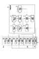
- FIG. 1 is a figure showing an example of the composition of the air-conditioning system containing the air-conditioning control device concerning one embodiment.
- FIG. 2 is a diagram illustrating an example of a hardware configuration of the air conditioning control device.
- FIG. 3 is a diagram illustrating the relationship between the energy saving operation and the indoor air conditioning state when the operation mode of the air conditioner is the cooling mode.
- FIG. 4 is a diagram illustrating an example of a data structure of log data.
- FIG. 5 is a flowchart illustrating an example of a processing procedure of log data acquisition processing.
- FIG. 6 is a flowchart illustrating an example of a processing procedure of model construction processing.
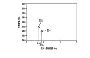
- FIG. 7 is a diagram in which the relationship between the energy saving operation time and the average room temperature is visualized as a plane scatter diagram.
- FIG. 1 is a figure showing an example of the composition of the air-conditioning system containing the air-conditioning control device concerning one embodiment.
- FIG. 2 is a diagram illustrating an example of a hardware
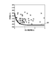
- FIG. 8 is a diagram in which the relationship between the energy saving operation time obtained for each energy saving operation and the average room temperature is visualized as a plane scatter diagram.
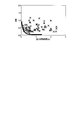
- FIG. 9 is a diagram showing threshold lines on a plane scatter diagram.
- FIG. 10 is a flowchart illustrating an example of a processing procedure of the discomfort degree estimation process.
- FIG. 11 is a diagram in which the relationship between the energy saving operation time and the dispersion value obtained for each energy saving operation is visualized as a plane scatter diagram together with a threshold line.
- FIG. 12 is a diagram for explaining an example of the configuration of the air conditioning control device 10 when data other than room temperature is used.
- FIG. 13 is a diagram for explaining an air conditioner that can control a plurality of indoor units with one refrigerant system.
- FIG. 1 shows an example of the configuration of an air conditioning system including an air conditioning control device according to the first embodiment.
- the air conditioning system includes an air conditioning control device 10 and an air conditioner connected to the air conditioning control device 10 via a transmission path.
- the air conditioner includes an indoor unit that is installed in a room (space) such as a room in a building and performs air conditioning of the room.
- a room space
- the air conditioning system will be described as including air conditioners 30A and 30B installed in the room 20, but the air conditioning system includes one air conditioner. It may be three or more.
- the room 20 may be the entire facility such as a house or a building, or may be a space in the facility that is distinguished by a floor, an inner wall, and the like.
- the air conditioner 30A performs air conditioning of the room 20 according to the set value of the air conditioning setting input via the remote controller 40A by, for example, a person in the room 20 (hereinafter referred to as a resident).
- a room temperature meter 50A for measuring the temperature (room temperature) of the room 20 is connected to the air conditioner 30A.
- the air conditioner 30A performs air conditioning based on the room temperature measured by the room temperature meter 50A.
- the air conditioner 30B performs air conditioning of the room 20 according to the set value of the air conditioning setting input by the occupant via the remote control 40B, for example.
- a room temperature meter 50B is connected to the air conditioner 30B, and the air conditioner 30B performs air conditioning based on the room temperature measured by the room temperature meter 50B.
- the above-described room temperature meters 50A and 50B may be incorporated in the air conditioners 30A and 30B, respectively, or may be arranged at different positions in the room 20. Furthermore, the room temperature meters 50A and 50B may be the same room temperature meter.
- the air conditioning control device 10 is a device for controlling the operation of the air conditioners 30A and 30B (that is, controlling the air conditioning of the room 20), and is provided in a management room of a building, for example.
- the air conditioning control device 10 is a device such as a BEMS (Building Energy Management System) that is introduced for the purpose of, for example, a building administrator grasping the air conditioning state of the room 20 or changing the settings of the air conditioners 30A and 30B.
- BEMS Building Energy Management System
- other equipment used in the air conditioning system may be used.
- the air conditioning control device 10 includes a log data acquisition unit 11, a log data storage unit 12, a model construction unit 13, a model storage unit 14, a discomfort degree estimation unit 15, and an operation control unit 16.
- the log data acquisition unit 11 acquires log data including the operation status of the air conditioners 30A and 30B and the history of the air condition of the room 20 from each of the air conditioners 30A and 30B.
- the log data is acquired at predetermined intervals and stored in the log data storage unit 12.
- the log data storage unit 12 stores log data including past operating conditions of the air conditioners 30A and 30B and past air conditioning conditions of the room 20.
- each of the air conditioners 30A and 30B is capable of energy-saving operation.
- the energy saving operation in the present embodiment is an operation of an air conditioner that realizes energy saving (that is, the air conditioning system operates with less energy), and includes, for example, the operation of the air conditioner in a state where the air conditioning setting is relaxed.
- the air conditioning setting is relaxed means that when the operation mode of the air conditioner is the cooling mode, the set temperature of the air conditioner is raised, and the operation mode of the air conditioner is the heating mode. In the case of the mode, it includes that the set temperature of the air conditioner is lowered.
- “releasing the air conditioning setting” may include, for example, reducing the air volume output from the air conditioner.
- the operation other than the energy saving operation is referred to as normal operation for convenience.
- the energy saving operation of each of the air conditioners 30A and 30B may be started in accordance with, for example, an operation on the remote controls 40A and 40B by a resident, or may be started according to a predetermined condition or the like.
- the conditions for starting the energy saving operation include, for example, that a predetermined time has been reached and that the room 20 has reached a predetermined temperature.
- the operation mode of each of the air conditioners 30A and 30B is the cooling mode
- the energy saving operation is started when the set temperature of the air conditioners 30A and 30B is in a time zone that tends to be raised by the occupants. May be.
- the energy saving operation is performed when the set temperature of the air conditioners 30A and 30B tends to be lowered by the occupants. May be started.
- the time zone in which the set temperature tends to increase and the time zone in which the set temperature tends to decrease may be specified from, for example, log data stored in the log data storage unit 12 or other data.
- the air conditioner is operated with less energy (electric power) than is normally required, so if the energy saving operation is continued, the indoor comfort gradually decreases, residents will eventually feel uncomfortable.
- the model construction unit 13 constructs a discomfort probability model based on the log data stored in the log data storage unit 12.
- the discomfort probability model is the degree of discomfort of the occupants in the room 20 based on the elapsed time since the start of the energy-saving operation and the air conditioning state of the room 20 (the degree that the occupants feel uncomfortable in the room 20). ) Is a model used for estimating.
- the discomfort probability model constructed by the model construction unit 13 is stored in the model storage unit 14. Details of the discomfort probability model will be described later.
- the discomfort degree estimation unit 15 estimates (evaluates) the discomfort level of the occupants using the discomfort probability model stored in the model storage unit 14 during the energy saving operation of the air conditioners 30A and 30B.
- the operation control unit 16 cancels the energy-saving operation of the air conditioners 30A and 30B based on the discomfort level estimated by the discomfort level estimation unit 15. In this case, the operation control unit 16 changes the direction so as to increase the air conditioning settings (for example, set temperature) of the air conditioners 30A and 30B.
- the air conditioning settings for example, set temperature
- increasing air conditioning settings is the opposite of “relaxing air conditioning settings” described above.
- the air conditioner when the operation mode of the air conditioner is the cooling mode, the air conditioner This includes that the set temperature is lowered, and that the set temperature of the air conditioner is raised when the operation mode of the air conditioner is the heating mode.
- the building administrator can display the log data stored in the log data storage unit 12 on the display device of the air conditioning control device 10 by operating the air conditioning control device 10. Further, the building manager can change the set value of the air conditioning setting of the air conditioners 30A and 30B or start the energy saving operation by operating the air conditioning control device 10 in the same manner as the remote controls 40A and 40B described above. is there.
- FIG. 2 shows an example of the hardware configuration of the air conditioning control device 10 according to the present embodiment.
- the air conditioning control device 10 includes a CPU 101, a nonvolatile memory 102, a main memory 103, a communication device 104, and the like.
- the CPU 101 is a hardware processor that controls the operation of various components in the air conditioning control device 10.
- the CPU 101 executes various programs loaded from the nonvolatile memory 102 that is a storage device to the main memory 103.
- the program executed by the CPU 101 includes an operating system and an application program (hereinafter referred to as an air conditioning control program) for controlling the operation of the air conditioners 30A and 30B.
- the CPU 101 also executes a basic input / output system (BIOS), which is a program for hardware control, for example.
- BIOS basic input / output system
- the air conditioning control device 10 is described as including the CPU 101, but the air conditioning control device 10 may include a processor or controller other than the CPU 101 as long as the above-described program can be executed. .
- some or all of the log data acquisition unit 11, the model construction unit 13, the discomfort degree estimation unit 15, and the operation control unit 16 illustrated in FIG. 1 cause the CPU 101 to execute an air conditioning control program. That is, it shall be realized by software. Part or all of these units 11, 13, 15 and 16 may be realized by hardware such as an IC (Integrated Circuit), or may be realized as a combination configuration of software and hardware.
- IC Integrated Circuit
- the log data storage unit 12 and the model storage unit 14 illustrated in FIG. 1 are realized by a storage device such as the nonvolatile memory 102 described above.
- the communication device 104 is a device configured to execute, for example, wired or wireless communication with an external device.
- the air conditioning control device 10 has been described as including the CPU 101, the nonvolatile memory 102, the main memory 103, and the communication device 104. However, the air conditioning control device 10 displays log data as described above. A display device and an input device for changing the setting values of the air conditioning settings of the air conditioners 30A and 30B may be further provided.
- FIG. 3 shows the relationship between the energy saving operation and the air conditioning state of the room 20 when the operation mode of the air conditioners 30A and 30B is the cooling mode.
- the upper part of FIG. 3 shows the transition of the set temperature of the air conditioner 30A in a visualized manner.
- the first energy saving operation flag in the upper part of FIG. 3 indicates whether the air conditioner 30A is in the energy saving operation, as will be described later.
- the middle part of FIG. 3 visualizes and shows the transition of the set temperature of the air conditioner 30B.
- the second energy-saving operation flag in the middle part of FIG. 3 indicates whether the air conditioner 30B is in the energy-saving operation to the amount described later.
- the lower part of FIG. 3 visualizes and shows the transition of the average value of the temperature (room temperature) of the room 20 as the set temperatures of the air conditioners 30A and 30B are raised and lowered.
- the average value of the room temperature demonstrated in FIG. 3 etc. shall be the average value of the temperature distribution of the room
- the energy saving operation of the air conditioner 30A is started at 10:30 when the temperature of the room 20 is lowered by the air conditioning performed by the air conditioners 30A and 30B (that is, the setting of the air conditioner 30A). The temperature has been raised). During the energy saving operation of the air conditioner 30A, the average value of the temperature in the room 20 gradually increases.
- the occupant in the room 20 felt uncomfortable because the room temperature was high at 11:25 when the average room temperature reached 26 ° C.
- the occupant can cancel the energy-saving operation of the air conditioner 30A by operating the remote controller 40A (that is, lower the set temperature of the air conditioner 30A). According to this, the room temperature falls again, and the comfort of the room 20 can be improved.
- an energy-saving operation of the air conditioner 30B is started at 13:35 when the temperature of the room 20 is lowered by the air conditioning performed by the air conditioners 30A and 30B (that is, the set temperature of the air conditioner 30B is increased). ) Is shown. During the energy saving operation of the air conditioner 30B, the average value of the temperature in the room 20 gradually increases.
- the occupants in the room 20 felt uncomfortable due to the high room temperature.
- the occupant can cancel the energy-saving operation of the air conditioner 30B (that is, lower the set temperature of the air conditioner 30B) by operating the remote controller 40B. According to this, the room temperature falls again, and the comfort of the room 20 can be improved.
- the energy saving operation is often started and canceled repeatedly depending on whether the occupant feels comfortable or uncomfortable as shown in FIG. .
- the operation status of the air conditioners 30A and 30B and the history of the air conditioning state (for example, room temperature) of the room 20 as described above are accumulated as log data in the air conditioning control device 10 (log data storage unit 12). .
- FIG. 4 shows an example of the data structure of the log data acquired by the log data acquisition unit 11 and stored in the log data storage unit 12 when the air conditioners 30A and 30B are operated as shown in FIG.
- the log data includes a first set temperature, a first room temperature, a first energy saving operation flag, a second set temperature, a second room temperature, a second energy saving operation flag, and an average room temperature in association with the time. included.
- the time is, for example, the time when the log data is acquired (or stored in the log data storage unit 12). In FIG. 4, the time is shown for convenience, but the time included in the log data is a concept including a date (that is, date and time).
- the first set temperature is the set temperature of the air conditioner 30A.
- the first room temperature is the temperature of the room 20 measured by the room temperature meter 50A.
- the first energy saving operation flag indicates whether the air conditioner 30A is in the energy saving operation. When the first energy saving operation flag is “0”, it indicates that the air conditioner 30A is not in energy saving operation, and when the first energy saving operation flag is “1”, the air conditioner 30A is in energy saving operation. Indicates.
- the second set temperature is the set temperature of the air conditioner 30B.
- the second room temperature is the temperature of the room 20 measured by the room temperature meter 50B.
- the second energy saving operation flag indicates whether or not the air conditioner 30B is in the energy saving operation as described above. When the second energy saving operation flag is “0”, it indicates that the air conditioner 30B is not in energy saving operation, and when the second energy saving operation flag is “1”, the air conditioner 30B is in energy saving operation. Indicates.
- the average room temperature is an average value of the first room temperature and the second room temperature.
- log data 121 is stored in the log data storage unit 12.
- the log data 121 includes a time “10:15”, a first set temperature “24”, a first room temperature “24.5”, a first energy saving operation flag “0”, a second set temperature “24”, a second room temperature “ 24.5 “, the second energy saving operation flag” 1 "and the average room temperature” 24.50 ".
- the set temperature of the air conditioner 30A is 24 ° C.
- the room temperature measured by the room temperature meter 50A is 24.5 ° C.
- the set temperature of the air conditioner 30B Is 24 ° C.
- the room temperature is 24.5 ° C. measured by the room temperature meter 50B
- the average room temperature is 24.50 ° C.
- the log data 121 indicates that the air conditioners 30A and 30B are not in an energy saving operation.
- Log data 122 includes time “10:30”, first set temperature “27”, first room temperature “24.0”, first energy saving operation flag “1”, second set temperature “24”, second room temperature “ 24.5 ”, the second energy saving operation flag“ 0 ”, and the average room temperature“ 24.25 ”.
- the set temperature of the air conditioner 30A is 27 ° C.
- the room temperature measured by the room temperature meter 50A is 24.0 ° C.
- the set temperature of the air conditioner 30B Is 24 ° C.
- the room temperature is 24.5 ° C. measured by the room temperature meter 50B
- the average room temperature is 24.25 ° C.
- the log data 122 indicates that the air conditioner 30A is in an energy saving operation and the air conditioner 30B is not in an energy saving operation.
- the first energy saving operation flag included in the log data stored in the log data storage unit 12 before the log data 122 is “0”.
- the first energy saving operation flag included in the log data 122 is “1”. According to this, it can be determined that the energy saving operation of the air conditioner 30A has been started between 10:25 and 10:30.
- the log data 123 includes the time “11:25”, the first set temperature “26”, the first room temperature “26.5”, the first energy saving operation flag “0”, and the second set temperature “24”. , The second room temperature “25.5”, the first energy saving operation flag “0”, and the average room temperature “26.00”.
- the set temperature of the air conditioner 30A is 26 ° C.
- the room temperature measured by the room temperature meter 50A is 26.5 ° C.
- the set temperature of the air conditioner 30B Is 24 ° C
- the room temperature is 25.5 ° C measured by the room temperature meter 50B
- the average room temperature is 26.00 ° C.
- the log data 123 indicates that the air conditioners 30A and 30B are not in an energy saving operation.
- the first energy saving operation flag included in the log data stored in the log data storage unit 12 one time before the log data 123 is “1”.
- the first energy saving operation flag included in the log data 123 is “0”. According to this, it is possible to determine that the energy saving operation of the air conditioner 30A has been canceled between 11:20 and 11:25.
- the time when the energy saving operation of each of the air conditioners 30A and 30B is started (time when the air conditioning setting is relaxed), the time when the energy saving operation is canceled. (Time when the air-conditioning setting is strengthened) and the air-conditioning state (for example, average room temperature) of the room 20 during that time can be specified.
- log data 121 to 125 have been described, but the same applies to other log data.
- FIG. 4 only a part of the log data stored in the log data storage unit 12 is shown, but the log data storage unit 12 acquires the data during operation of the air conditioners 30A and 30B. It is assumed that all log data is stored. Note that, among the log data stored in the log data storage unit 12, log data for which a predetermined period has elapsed since being stored in the log data storage unit 12 may be discarded.
- the log data is stored in the log data storage unit 12 so that the time is 5 minutes (that is, the log data is accumulated at intervals of 5 minutes).
- the log data may be accumulated at different intervals as long as the start and release can be determined. Further, the interval at which log data is accumulated is not a fixed time interval but may be irregular.
- the energy saving operation flag (first and second energy saving operation flags) has been described as being managed for each of the air conditioners 30A and 30B.
- the energy saving operation flag is provided with an air conditioner. It may be managed for each room (indoor).
- log data acquisition processing processing when acquiring log data
- the log data acquisition process is executed at a predetermined interval (for example, every five minutes) by the log data acquisition unit 11 included in the air conditioning control device 10.
- the operation mode of the air conditioners 30A and 30B will be described as being the cooling mode.
- the log data acquisition unit 11 uses the set temperature of the air conditioner 30A and the room temperature measured by the room temperature meter 50A and the set temperature of the air conditioner 30B and the room temperature measured by the room temperature meter 50B of the air conditioners 30A and 30B. It acquires from each (step S1).
- the log data acquisition unit 11 uses the set temperature of the air conditioner 30 ⁇ / b> A acquired in step S ⁇ b> 1 and the latest log data (the latest from the current time) among the log data stored in the log data storage unit 12. Based on this, a first energy saving operation flag is determined (step S2).
- step S2 the process of step S2 will be described in detail.
- the case where the air conditioner 30A is not in the energy saving operation and the case where the air conditioner 30A is in the energy saving operation will be described separately.
- step S2 when the air conditioner 30A is not in an energy saving operation will be described.
- the set temperature of the air conditioner 30A acquired in step S1 is higher than the first set temperature included in the latest log data, that is, the set temperature of the air conditioner 30A is increased. If it is determined that the air conditioning setting has been relaxed, it is determined that the energy saving operation of the air conditioner 30A has started. On the other hand, when the set temperature of the air conditioner 30A acquired in step S1 is the same as or lower than the first set temperature included in the latest log data, the set temperature of the air conditioner 30A has not been raised. It is determined that the energy saving operation of 30A has not been started (that is, the normal operation is continued).
- step S2 When it is determined that the energy saving operation of the air conditioner 30A has been started as described above, “1” is determined as the first energy saving operation flag in step S2. On the other hand, when it is determined that the energy saving operation of the air conditioner 30A has not been started, “0” is determined as the first energy saving operation flag in step S2.
- step S2 when the air conditioner 30A is in the energy saving operation will be described.
- the set temperature of the air conditioner 30A acquired in step S1 is lower than the first set temperature included in the latest log data, that is, the set temperature of the air conditioner 30A is If it is lowered (the air conditioning setting is strengthened), it is determined that the energy saving operation of the air conditioner 30A has been released.
- the set temperature of the air conditioner 30A acquired in step S1 is the same as or higher than the first set temperature included in the latest log data, the set temperature of the air conditioner 30A has not been lowered. It is determined that the energy saving operation of 30A has not been canceled (that is, the energy saving operation is continued).
- step S2 When it is determined that the energy saving operation of the air conditioner 30A has been canceled as described above, “0” is determined as the first energy saving operation flag in step S2. On the other hand, when it is determined that the energy saving operation of the air conditioner 30A has not been canceled, “1” is determined as the first energy saving operation flag in step S2.
- the log data acquisition unit 11 performs the second energy saving operation based on the set temperature of the air conditioner 30B acquired in step S1 and the latest log data among the log data stored in the log data storage unit 12. A flag is determined (step S3).
- step S3 is performed by using the set temperature of the air conditioner 30A acquired in step S1 and the first set temperature included in the latest log data as the set temperature of the air conditioner 30B acquired in step S1 and the latest log. Except for the second set temperature included in the data, the process is the same as the process of step S2, and therefore detailed description thereof is omitted here.
- the log data acquisition unit 11 calculates the average room temperature (room temperature measured by the room temperature meters 50A and 50B) acquired in step S1 as the average room temperature (step S4).
- the log data acquisition unit 11 measures the set temperature (first set temperature) of the air conditioner 30A acquired in step S1 and the room temperature meter 50A, for example, in association with the current time.
- log data as described in FIG. 4 is automatically acquired and stored in the log data storage unit 12 based on the set temperature and room temperature from the air conditioners 30A and 30B. Can do.
- step S2 for example, if the set temperature of the air conditioner 30A is lowered when the air conditioner 30A is not in the energy saving operation, it is determined that the energy saving operation has started, and “1” is set as the first energy saving operation flag. Is determined.
- step S3 when the air conditioner 30A is in the energy saving operation and the set temperature of the air conditioner 30A is raised, it is determined that the energy saving operation has been released, and “0” is determined as the first energy saving operation flag. The same applies to step S3.
- log data including the first and second energy saving operation flags “0” is stored (that is, “0” is determined as the first and second energy saving operation flags in steps S2 and S3).
- the first and second energy saving operation flags in this case may be determined based on, for example, the set temperatures and operation modes of the air conditioners 30A and 30B.
- the energy-saving operation flag is determined on the air-conditioning control device 10 side. For example, information indicating whether or not the air-conditioners 30A and 30B are in the energy-saving operation includes the air-conditioner.
- the configuration may be acquired from 30A and 30B.
- the air conditioning control device 10 constructs a discomfort probability model based on the log data described above, and estimates the discomfort level of the occupant using the constructed discomfort probability model, The energy saving operation of each of the air conditioners 30A and 30B can be canceled.
- model construction process a process of constructing a discomfort probability model
- discomfort degree estimation process a process of estimating the discomfort level of the occupant in the present embodiment
- the model construction unit 13 acquires log data stored in the log data storage unit 12 (step S11).
- the model construction unit 13 specifies the energy saving operation start time (date and time) and energy saving operation release time (date and time) for each of the air conditioners 30A and 30B based on the acquired log data (step S12).
- the energy saving operation start time is the time when the energy saving operation is started as described above
- the energy saving operation release time is the time when the energy saving operation is released.
- the energy saving operation start time of the air conditioner 30A corresponds to the time when the first energy saving operation flag included in the log data is changed from “0” to “1”.
- the energy-saving operation cancellation time of the air conditioner 30A corresponds to the time when the first energy-saving operation flag included in the log data is changed from “1” to “0”.
- the energy saving operation start time of the air conditioner 30B corresponds to the time when the second energy saving operation flag included in the log data is changed from “0” to “1”.
- the energy-saving operation cancellation time of the air conditioner 30B corresponds to the time when the second energy-saving operation flag included in the log data is changed from “1” to “0”.
- the model construction unit 13 calculates the time from the energy-saving operation start time specified in step S12 to the energy-saving operation release time (hereinafter referred to as energy-saving operation time) (step S13).
- the energy saving operation time corresponds to a time until an operation is performed after the energy saving operation is started and an occupant feels uncomfortable and changes the set temperature (that is, cancels the energy saving operation).
- the model building unit 13 acquires the average room temperature at the time of the energy-saving operation release time (step S14). In this case, the model construction unit 13 acquires the average room temperature included in the log data including the energy saving operation cancellation time.
- step S12 which is the time included in the log data 122 in which the first energy-saving operation flag is changed from “0” to “1”, is air-conditioned. It is specified as the energy saving operation start time of the machine 30A. Further, 11:25, which is the time included in the log data 123 in which the first energy saving operation flag is changed from “1” to “0”, is specified as the energy saving operation release time of the air conditioner 30A. In this case, in step S13, 55 minutes is calculated as the energy saving operation time of the air conditioner 30A. In this case, in step S14, 26.00 ° C., which is the average room temperature included in the log data 123, is acquired.
- step S12 13:35, which is the time included in the log data 124 in which the second energy saving operation flag is changed from “0” to “1”, is specified as the energy saving operation start time of the air conditioner 30B. Is done. Also, 14:20, which is the time included in the log data 125 in which the second energy saving operation flag is changed from “1” to “0”, is specified as the energy saving operation release time of the air conditioner 30B. In this case, in step S13, 45 minutes is calculated as the energy saving operation time of the air conditioner 30B. In this case, in step S14, 27.00 ° C., which is the average room temperature included in the log data 125, is acquired.
- FIG. 7 is a diagram in which the relationship between the energy saving operation time calculated in step S13 and the average room temperature acquired in step S14 (that is, the average room temperature when the energy saving operation is released) is visualized as a plane scatter diagram.
- the average room temperature is the vertical axis and the energy saving operation time is the horizontal axis.
- FIG. 8 is a diagram in which the relationship between the energy saving operation time and the average room temperature obtained by executing the processing of steps S12 to S14 for each energy saving operation is visualized as a plane scatter diagram.
- each of the X marks in FIG. 8 feels uncomfortable for the occupant after the energy-saving operation is started. It shows the relationship between the time until (energy-saving operation is canceled) and the average room temperature at that time. In other words, FIG. 8 shows that how much room temperature has passed since the start of energy-saving operation and what room temperature would be uncomfortable for the occupants. I can say that.
- the energy-saving operation is released early when the room temperature is high after the energy-saving operation is started (that is, the occupant feels uncomfortable early).
- the energy-saving operation is not easily released (that is, the occupant is less likely to feel uncomfortable even in the energy-saving operation).
- the shorter the energy saving operation time and the lower the average room temperature the lower the discomfort of the occupants (the probability that the occupants can cancel the energy saving operation).
- the longer the energy saving operation time (the time has elapsed since the energy saving operation started) and the higher the average room temperature the higher the discomfort of the occupants.
- a relationship between an energy saving operation time (that is, an elapsed time since the energy saving operation is started) and an average room temperature when the energy saving operation is canceled is defined.
- a discomfort probability model shall be constructed.
- the model construction unit 13 determines the discomfort level of the occupants in the relationship (coordinates in the plane scatter diagram) between each energy saving operation time and the average room temperature when the energy saving operation is canceled as shown in FIG.
- a threshold line for estimating is generated (step S15).
- the threshold line generated in step S15 is, for example, a curve obtained by classifying a state where the occupant feels uncomfortable and a state where the occupant feels uncomfortable.
- a classification method for generating the threshold line for example, a method such as a 1-class support vector machine can be used, but other classification methods may be used.
- FIG. 9 is a diagram showing the threshold lines generated in step S15 on the plane scatter diagram shown in FIG. According to the threshold line 301 shown in FIG. 9, it is estimated that the discomfort level of the occupant is low in the region below the threshold line 301 (energy saving operation time and average room temperature), and the region above the threshold line 301. In (energy saving operation time and average room temperature), the occupant's discomfort is estimated to be high.
- the model construction unit 13 uses such a threshold line, the above-described energy saving operation time, the average room temperature when the energy saving operation is canceled, and the discomfort corresponding to the energy saving operation time and the average room temperature (energy saving operation is canceled).
- a discomfort probability model in which the relationship with the probability is defined (step S16).
- the discomfort probability model constructed in step S16 is a 3D model in which discomfort is added to the relationship between the energy saving operation time described in FIGS. 7 to 9 and the average room temperature when the energy saving operation is canceled.
- this discomfort probability model with the above threshold line as a boundary, for example, the shorter the energy saving operation time and the lower the average room temperature, the lower the discomfort level is output, the longer the energy saving operation time and the higher the average room temperature. It is specified that a higher degree of discomfort is output.
- the discomfort probability model generated in step S16 is stored (registered) in the model storage unit 14 (step S17).
- the above-described model construction process (the process shown in FIG. 6) may be executed when, for example, a predetermined number of log data is stored in the log data storage unit 12, or the energy saving operation is canceled, for example. It may be executed when log data (for example, log data 123 and 125 shown in FIG. 4) that can be determined is stored in the log data storage unit 12.
- log data for example, log data 123 and 125 shown in FIG. 4
- log data acquired from other rooms (spaces) or buildings, etc. May be prepared in advance, and a discomfort probability model may be constructed based on the log data.
- the model building process is executed for each operation mode of the air conditioner. That is, in the present embodiment, a discomfort probability model for the cooling mode is constructed based on the log data acquired when the air conditioners 30A and 30B are operating in the cooling mode, and the air conditioners 30A and 30B are heated. A discomfort probability model for the heating mode is constructed based on the log data acquired when operating in the mode.
- the model construction process is described as being executed in the air conditioning control device 10, but the model construction processing may be executed outside the air conditioning control device 10. In this case, the discomfort probability model constructed by the model construction process executed outside the air conditioning control device 10 only needs to be stored in the model storage unit 14.
- the discomfort probability model stored in the model storage unit 14 may be updated based on the log data newly stored in the log data storage unit 12 after the discomfort probability model is constructed.
- the process shown in FIG. 10 is executed by the discomfort degree estimation unit 15 and the operation control unit 16 included in the air conditioning control device 10.
- the model storage unit 14 stores a discomfort probability model constructed by executing the model construction process described above.
- the discomfort degree estimation unit 15 refers to the log data stored in the log data storage unit 12 to determine whether the air conditioner 30A or the air conditioner 30B is in an energy saving operation (step S21).
- step S21 when the first energy saving operation flag included in the latest log data among the log data stored in the log data storage unit 12 is “1”, the air conditioner 30A is in the energy saving operation.
- the second energy saving operation flag included in the latest log data is “1”
- step S21 will be specifically described with reference to FIG. 4.
- the latest log data includes time “10:55”. This is log data, and the first energy-saving operation flag included in the log data is “1”.
- the air conditioner 30A is in an energy saving operation. Since the second energy saving operation flag in this case is “0”, the air conditioner 30B is not in the energy saving operation.
- the latest log data is log data including the time “13:55”, and the second data included in the log data.
- the energy saving operation flag is “1”. In this case, it is determined that the air conditioner 30B is in an energy saving operation. In this case, since the first energy saving operation flag is “0”, the air conditioner 30A is not in the energy saving operation.
- the latest log data is log data including the time “11:25”, and the first and Both the second energy saving operation flags are “0”. In this case, it is determined that the air conditioners 30A and 30B are not in the energy saving operation.
- the latest log data is log data including the time “14:25”, and the first log data included in the log data
- the second energy saving operation flag is both “0”. In this case, it is determined that the air conditioners 30A and 30B are not in the energy saving operation.
- step S21 When it is determined in step S21 that the air conditioner 30A or 30B is in the energy saving operation (YES in step S11), the discomfort degree estimation unit 15 receives the latest log data (hereinafter referred to as the first log) from the log data storage unit 12. Log data in which the energy saving operation flag (first or second energy saving operation flag) is changed from “0” to “1” (hereinafter referred to as second log data) is acquired (step S22).
- the energy saving operation flag first or second energy saving operation flag
- the time included in the first log data corresponds to the current time.
- the time included in the second log data corresponds to the time when the energy saving operation is started (energy saving operation start time).
- the discomfort degree estimation part 15 is based on the time contained in the 1st log data, and the time contained in the 2nd log data, and the current energy saving operation time (the elapsed time from the start of the energy saving operation to the present) Is calculated (step S23).
- the discomfort level estimation unit 15 estimates the discomfort level of the occupants in the room 20 using the discomfort probability model stored in the model storage unit 14 (step S24).
- the discomfort degree estimation unit 15 acquires the average room temperature (that is, the current average room temperature) included in the first log data as the current air conditioning state of the room 20, and the energy saving operation time calculated in step S23;
- the acquired average room temperature is applied to the discomfort probability model.
- the discomfort degree defined in the discomfort probability model is output in association with the relationship between the current energy saving operation time and the average room temperature.
- step S24 as described above, as the energy saving operation time is shorter and the average room temperature is lower, the lower discomfort is estimated (output), and as the energy saving operation time is longer and the average room temperature is higher, it is higher. The degree of discomfort is estimated (output).
- the discomfort probability model used here is a discomfort probability model (cooling discomfort probability model or heating discomfort probability model) corresponding to the operation mode of the air conditioners 30A and 30B.
- the discomfort degree estimation unit 15 determines whether or not the discomfort degree thus estimated is equal to or greater than a predetermined value (hereinafter referred to as a threshold value) (step S25).
- the operation control unit 16 executes a process for canceling the energy saving operation.
- the operation control unit 16 determines the set temperature (the set value of the air conditioning setting) after canceling the energy-saving operation (step S26).
- the set temperature determined in step S26 can be set to a set temperature immediately before the energy saving operation is started, for example.
- the set temperature immediately before the energy saving operation is started can be acquired from the set temperature (first or second set temperature) of the air conditioner during the energy saving operation included in the log data immediately before the second log data.
- the set temperature determined in step S26 may be a temperature that is changed in a direction in which the current set temperature is increased by a predetermined value, for example, a temperature that is predetermined by a building administrator or the like. Also good.
- the operation control unit 16 changes the set temperature of the air conditioner (air conditioner 30A or 30B) during the energy saving operation to the set temperature determined in step S16 (step S27). For example, when both the air conditioners 30A and 30B are in an energy saving operation, the set temperatures of the air conditioners 30A and 30B may be changed to the same set temperature (predetermined set temperature), respectively. It may be changed to a different set temperature (set temperature before the energy saving operation of each of the air conditioners 30A and 30B is started).
- step S27 When the process of step S27 is executed, the operation control unit 16 outputs a control signal indicating the set temperature (release of energy saving operation) determined in step S26 to the air conditioner during energy saving operation. According to this, the energy saving operation of the air conditioner during the energy saving operation is canceled, and the operation at the set temperature changed in step S27 is started.
- step S21 when it is determined in step S21 that the air conditioners 30A and 30B are not in the energy saving operation (NO in step S21), the processing in FIG. Similarly, when it is determined in step S25 that the degree of discomfort is not equal to or greater than the threshold value (less than the threshold value) (NO in step S25), the processing in FIG.
- the above-described discomfort level estimation process (the process shown in FIG. 10) is executed periodically, for example.
- the discomfort degree estimation process can be executed, for example, every time new log data is acquired (stored) (that is, at intervals of 5 minutes), but from the interval at which the log data is acquired. May be executed at long intervals (for example, at intervals of 10 minutes or 30 minutes).
- the air conditioning state for example, average room temperature
- the acquired air conditioning state and the air conditioner 30A or 30B The energy saving operation is canceled by applying the elapsed time from the start of the energy saving operation to the present time (that is, the current energy saving operation time) to the discomfort probability model.
- the discomfort probability model it is possible to estimate the discomfort level of the occupants in the room 20 based on the current air conditioning state and the energy saving operation time, and such discomfort level is equal to or greater than a threshold value. In this case, energy-saving operation is canceled.
- the setting of the air conditioner 30A or 30B during the energy saving operation is changed to the setting before the energy saving operation is started.
- the occupant cancels the energy-saving operation of the air conditioner 30A or 30B during the energy-saving operation by operating the remote controller 40A or 40B. (In other words, there is a possibility that the air-conditioning setting is changed in a direction to be strengthened).
- the air-conditioning setting may be further strengthened when the process for canceling the energy-saving operation is further executed. In this case, not only may there be a possibility of impairing the comfort of the occupants, but it will also be contrary to energy saving.
- the air conditioner 30A when the occupant performs a release operation during the energy saving operation of the air conditioner 30A, the air conditioner 30A is in the energy saving operation by the log data acquisition process described above.
- the log data including the first energy saving operation flag “0” indicating that it is not is stored in the log data storage unit 12.
- step S21 of the discomfort degree estimation process shown in FIG. 10 since it is determined that the air conditioner 30A is not in the energy saving operation, the processes after step S22 are not executed.
- the air-conditioning control device 10 cancels the energy-saving operation. Since no further setting change is performed, it is possible to avoid impairing the comfort of the occupants described above and improve energy saving performance.
- the case where the air conditioner 30A is in the energy saving operation has been mainly described, but the same applies to the case where the air conditioner 30B is in the energy saving operation.
- log data storage unit 12 stores log data including the date and time when energy-saving operation was started in the past, the date and time when the energy-saving operation was canceled by the occupant, and the past air conditioning state of room 20.
- a discomfort probability model can be constructed based on the log data.
- This discomfort probability model may be constructed (generated) outside the air conditioning control device 10 and stored in advance in the model storage unit 14 of the air conditioning control device 10, for example.
- the operation modes of the air conditioners 30A and 30B include a cooling mode and a heating mode.
- the air conditioners 30A and 30B are operating in the cooling mode, the occupant's discomfort level is estimated.
- a discomfort probability model constructed based on log data acquired during operation in the cooling mode is used.
- the discomfort constructed based on the log data acquired during the operation in the heating mode is used.
- a probabilistic model is used. That is, in this embodiment, the discomfort degree of the occupant can be estimated using different discomfort probability models according to the operation modes of the air conditioners 30A and 30B.
- the discomfort probability model is simply defined as a relationship between the energy-saving operation time and the average room temperature. It may be a model. According to such a discomfort probability model, for example, the position (coordinates) on the plane scatter diagram determined by the relationship between the current energy-saving operation time and the average room temperature indicates that the occupants classified by the threshold lines are uncomfortable. It can be set as the structure which cancel
- FIG. 11 is the figure which visualized the relationship between each energy saving operation time and a dispersion
- a discomfort probability model is constructed based on the dispersion value of the past temperature (room temperature) of the room 20, and the dispersion value of the temperature of the room 20 acquired as the current air conditioning state of the room 20 is calculated with respect to the discomfort probability model.
- the dispersion value is used instead of the average room temperature
- the maximum value or the minimum value among the room temperatures measured by a plurality of room temperature meters can be used. It is also possible to construct a multivariate model by combining some of average room temperature, dispersion, maximum value and minimum value of room temperature.
- a room temperature meter automatically arranged at a position capable of measuring a room temperature easily associated with a high degree of discomfort among a plurality of room temperature meters arranged in the room 20 is automatically used. It is also possible to select and use only the room temperature measured by the selected room temperature meter. According to such a configuration, for example, it is possible to cope with a case where there are a plurality of places where the effectiveness of air conditioning tends to deteriorate.
- the air conditioning control device 10 can be configured as shown in FIG. In FIG. 12, the same reference numerals are assigned to the same parts as those in FIG.
- the air conditioning control device 10 further includes, for example, a weather log storage unit 17a, a distribution board log storage unit 17b, and a resident log storage unit 17c.
- the weather log storage unit 17a stores a weather log reflecting the outside air load of the air conditioners 30A and 30B.
- the weather log includes, for example, outside air temperature, solar radiation, wind speed, and precipitation.
- the weather log may be measured by using various sensors, for example, or acquired (collected) from an external server device or the like. May be.
- the distribution board log storage unit 17b stores distribution board logs (hereinafter referred to as distribution board logs) that reflect the heat generated by various devices (hereinafter referred to as indoor apparatuses) arranged in the room 20. Has been.
- the distribution board log includes the operation amount of the indoor device that can be acquired from the distribution board. According to such a distribution board log, heat generation or the like in the indoor device can be obtained.
- the occupancy log storage unit 17c stores a log of the number of occupants in the room 20 that reflects the heat generated by the occupants in the room 20 (hereinafter referred to as occupancy log).
- the occupancy log (the number of occupants) may be acquired using, for example, a time card system related to the occupants in the room 20, an infrared sensor disposed in the room 20, or the like. It may be acquired by analyzing an image of a camera.
- the air conditioning control device 10 may include at least one of the weather log storage unit 17a, the distribution board log storage unit 17b, and the occupant log storage unit 17c illustrated in FIG.
- the weather log, distribution board log, and attendance log described above may be used in place of the room temperature described in the present embodiment, or may be used in combination with the room temperature.
- the weather log, the distribution board log, and the occupant log have been described as data other than room temperature.
- the data other than room temperature may be data such as humidity and carbon dioxide concentration in the room 20, for example.
- the humidity and the carbon dioxide concentration in the room 20 may be measured by a hygrometer and a carbon dioxide concentration meter disposed in the room 20 in the same manner as the room temperature meters 50A and 50B.
- the log data has been described as including the first and second energy saving operation flags.
- the first and second energy saving operation flags may not be included in the log data.
- the energy saving operation start time and the energy saving operation release time in step S12 shown in FIG. 6 may be specified based on changes in the first and second set temperatures included in the log data. The same applies to the determination processing of whether or not the air conditioners 30A and 30B in step S21 shown in FIG.
- the log data may be configured so that the average room temperature is not included.
- the average room temperature of the first and second room temperatures included in the log data may be calculated every time the process of step S14 shown in FIG.
- Air conditioners include indoor units installed indoors and outdoor units installed outdoors. In general air conditioners, about 90% of the required power is consumed by outdoor units. For this reason, when an upper limit is provided in power consumption as described above, it is necessary to control (change) the operation of the outdoor unit.
- an air conditioner capable of controlling a plurality of indoor units with one refrigerant system.
- the system often spans a plurality of rooms.
- indoor units 30A and 30B are installed in the indoor 20A
- an indoor unit 30C is installed in the indoor 20B
- the outdoor unit 70 installed in the outdoor 60 is like this. Heat is distributed to the indoor units 30A to 30C via the refrigerant pipe.
- the operation of the indoor units 30A to 30C is controlled according to the required amount from each of the indoor units 30A to 30C according to the set temperature and room temperature.
- the required amount from each of the indoor units 30A to 30C includes concepts such as the amount of electric power or the amount of heat necessary for air conditioning in each of the indoor units 30A to 30C.
- the indoor units 30A to 30C can be operated (operated) as required by the indoor units 30A to 30C.
- the total required amount total amount of power consumption required to operate the indoor units 30A to 30C as required by the indoor units 30A to 30C
- the ratio of the upper limit value of the power consumption is R
- the value obtained by multiplying each of the requested amounts from the indoor units 30A to 30C by R is the actual consumption amount (actual consumption amount) of the indoor unit.
- the whole air conditioner can be operated within the range of the upper limit value of power consumption.
- the building administrator may be able to specify (set) the actual consumption for each indoor unit, but the demand varies from moment to moment, so an upper limit is set for power consumption for the entire air conditioner. It is difficult for the building manager to specify the actual consumption amount for each air conditioner in real time.
- the air conditioner In the control of the air conditioner based on the upper limit value of the power consumption described above, heat is consumed regardless of the discomfort level of each of the rooms 20A and 20B.
- the indoor air conditioning capacity actual consumption of indoor units installed in a room with high discomfort
- the upper limit value of power consumption must be canceled (that is, the energy-saving operation of each of the indoor units 30A to 30C is canceled). Even though the operation can be continued, the energy-saving operation is canceled, resulting in an opportunity loss.
- the actual consumption of the indoor units 30A to 30C is controlled according to the degree of discomfort of the occupants in each of the rooms 20A and 20B.
- the degree is kept within a predetermined range, and energy saving operation (operation within the upper limit value of power consumption) is continued for a longer time.
- FIG. 14 shows an example of the configuration of an air conditioning system including an air conditioning control device according to the present embodiment. Note that portions similar to those in FIG. 1 described above are denoted by the same reference numerals, and detailed description thereof is omitted. Here, parts different from FIG. 1 will be mainly described.
- the hardware configuration of the air-conditioning control apparatus 10 according to the present embodiment is the same as that of the first embodiment described above, and will be described with reference to FIG. 2 as appropriate.
- the indoor units 30A and 30B are installed in the indoor 20A, and the indoor unit 30C is installed in the indoor 20B.
- the outdoor unit 70 installed in the outdoor 60 is connected via a refrigerant pipe so as to distribute heat to the indoor units 30A to 30C.
- indoor units 30A and 30B correspond to the air conditioners 30A and 30B in the first embodiment described above.
- the indoor unit 30C, the remote controller 40C, and the room temperature meter 50C are the same as the indoor unit 30A, the remote controller 40A, the room temperature meter 50A, and the like except that the installed (arranged) location is the room 20B. Description is omitted.
- the air conditioning control device 10 includes an installation data storage unit 18 and an upper limit setting unit 19.
- the installation data storage unit 18 stores in advance data indicating the location (indoor) where each indoor unit is installed (hereinafter referred to as installation data).
- the upper limit setting unit 19 sets an upper limit of power consumption of the entire air conditioner (hereinafter referred to as a power upper limit value).
- the power upper limit value may be specified by, for example, a building manager or the like, or a predetermined value may be automatically set at a predetermined time.
- the operation control unit 16 in the present embodiment based on the estimation result of the discomfort level for each of the indoors 20A and 20B by the discomfort level estimation unit 15, the actual consumption amount of each of the indoor units 30A to 30C. It has a function to control.
- FIG. 15 shows an example of the data structure of the installation data stored in the installation data storage unit 18 shown in FIG.
- the installation data includes an indoor ID and an indoor unit ID.
- the room ID is an identifier for identifying the room in which the indoor unit is installed.
- the indoor unit ID is an identifier for identifying an indoor unit installed in a room identified by the indoor ID associated with the indoor unit ID.
- the installation data storage unit 18 stores a plurality of installation data including installation data 181 to 183.
- the installation data 181 includes an indoor ID “20A” and an indoor unit ID “30A”. According to the installation data 181, the indoor unit identified by the indoor unit ID “30A” (here, the indoor unit 30A) is installed in the room identified by the indoor ID “20A” (here, the room 20A). It has been shown that
- the installation data 182 includes an indoor ID “20A” and an indoor unit ID “30B”. According to the installation data 182, the indoor unit identified by the indoor unit ID “30B” (here, the indoor unit 30B) is installed in the room identified by the indoor ID “20A” (here, the room 20A). It has been shown that
- the installation data 183 includes an indoor ID “20B” and an indoor unit ID “30C”. According to the installation data 183, the indoor unit (here, the indoor unit 30C) identified by the indoor unit ID “30C” is installed in the room (here, the room 20B) identified by the room ID “20B”. It has been shown that
- FIG. 16 shows an example of the data structure of log data stored in the log data storage unit 12 in the present embodiment.
- the first set temperature, the first room temperature, the first energy saving operation flag, the first required amount, the second set temperature, the second room temperature, and the second energy saving operation are associated with the time.
- the flag, the second required amount, the third set temperature, the third room temperature, the third energy saving operation flag, and the third required amount are included.
- the first set temperature, the first room temperature, the first energy saving operation flag, the second set temperature, the second room temperature, and the second energy saving operation flag are the same as those in the first embodiment, Detailed description is omitted.
- the first requested amount indicates the requested amount from the indoor unit 30A.
- the second request amount indicates the request amount from the indoor unit 30B.
- the third set temperature is the set temperature of the indoor unit 30C.
- the third room temperature is the room temperature of the room 20B measured by the room temperature meter 50C.
- the third energy saving operation flag indicates whether the indoor unit 30C is in an energy saving operation. When the third energy saving operation flag is “0”, it indicates that the indoor unit 30C is not in energy saving operation, and when the third energy saving operation flag is “1”, the indoor unit 30C is in energy saving operation. Indicates.
- the third request amount indicates the request amount from the indoor unit 30C.
- the log data includes the requested amount from each of the indoor units 30A to 30C at the time included in the log data.
- the air conditioning control apparatus 10 executes each of log data acquisition processing and model construction processing, as in the first embodiment described above.
- the requested amount included in the log data is acquired from each of the indoor units 30A to 30C (that is, the log data including the requested amount is stored in the log data storage unit 12). Except for this point, the second embodiment is the same as the first embodiment described above, and a detailed description thereof will be omitted.
- the model construction process in this embodiment is executed for each of the rooms 20A and 20B (that is, rooms).
- the log data stored in the log data storage unit 12 is divided into log data relating to the rooms 20A and 20B, and each of the log data relating to the rooms 20A and 20B.
- the above-described processing shown in FIG. 6 is executed.
- the discomfort probability model is constructed for each of the rooms 20A and 20B.
- the log data related to the room 20A includes the time, the first set temperature (the set temperature of the indoor unit 30A), the first room temperature (the room temperature measured by the room temperature meter 50A), the first shown in FIG. Energy saving operation flag (flag indicating whether indoor unit 30A is in energy saving operation), second set temperature (set temperature of indoor unit 30B), second room temperature (room temperature measured by room temperature meter 50B) and second
- the log data related to the room 20B includes the time, the third set temperature (the set temperature of the indoor unit 30C), the third room temperature (the room temperature measured by the room temperature meter 50C), and the third shown in FIG.
- This is log data including an energy saving operation flag (a flag indicating whether the indoor unit 30C is in an energy saving operation).
- the process shown in FIG. 6 is executed based on the log data related to the room 20B, for example, the third room temperature is acquired in step S14.
- the log data relating to the indoors 20A and 20B described above can be obtained by specifying the indoor units installed in the indoors 20A and 20B based on the installation data stored in the installation data storage unit 18, thereby providing a log data storage unit. 12 can be obtained.
- the process of controlling the actual consumption of the indoor units 30A to 30C in accordance with the discomfort level of the occupants in each room 20A and 20B (hereinafter referred to as the actual consumption control process). (Notation).
- the discomfort degree estimation unit 15 determines whether or not the power upper limit (unit: W) is set by the upper limit setting unit 19 (step S31).
- the discomfort level estimation unit 15 executes a discomfort level estimation process (step S32).
- the discomfort degree estimation process in step S32 the above-described processes in steps S21 to S25 shown in FIG. 10 are executed for each of the rooms 20A and 20B. According to this, in step S32, it is possible to identify a room having a discomfort level equal to or greater than the threshold value among the rooms 20A and 20B.
- the room where the discomfort degree is equal to or greater than the threshold is the room 20A
- the room 20B is assumed that the discomfort degree is not above the threshold.
- at least one of the indoor units (in this case, the indoor units 30A and 30B) installed in the indoor 20A is in an energy saving operation.
- the energy saving operation in the present embodiment refers to a state in which an operation is performed with an actual consumption amount smaller than a required amount from the air conditioner.
- the operation control unit 16 refers to the installation data storage unit 18 and identifies a set of indoor units installed in a room whose discomfort level is equal to or greater than a threshold value (hereinafter referred to as an indoor unit set) (step). S33). As described above, assuming that the room with the discomfort degree equal to or greater than the threshold is the room 20A, the indoor units 30A and 30B are specified as the indoor unit set in step S33.
- the operation control unit 16 requests each of the indoor units 30A and 30B (first and second request amounts) included in the latest log data among the log data stored in the log data storage unit 12. Is acquired (step S34).
- the request amount acquired in step S34 corresponds to the current request amounts of the indoor units 30A and 30B.
- step S34 When the process of step S34 is executed, the operation control unit 16 calculates E by the following formula (1) (step S35).
- Equation (1) L is the upper limit value of electric power, U is an indoor unit set, and k is an indoor unit (number) belonging to the indoor unit set. In addition, Sk indicates a required amount (unit: W) of the indoor unit k.
- E calculated in step S35 is necessary for operating each of the indoor units k (in this case, the indoor units 30A and 30B) belonging to the indoor unit set U from the above power upper limit value L as required. It is a value obtained by subtracting the total amount of power consumption. In other words, E can consume the indoor unit 30C installed in the room 20B having a low degree of discomfort when the indoor units 30A and 30B installed in the room 20A having a high level of discomfort are operated as required. It shows the amount of power.
- step S35 determines whether or not E calculated in step S35 is a value larger than 0 (that is, E> 0) (step S36).
- the operation control unit 16 calculates the actual consumption amount (unit) of each of the indoor units 30A to 30C according to the following formulas (2) and (3). : W) is determined (step S37).
- the actual consumption amount Sk ′ of each indoor unit k belonging to the indoor unit set U specified in step S33 is the required amount Sk of each indoor unit k. That is, the actual consumption amount of the indoor unit 30A installed in the indoor 20A having a high degree of discomfort is the required amount of the indoor unit 30A, and the actual consumption amount of the indoor unit 30B is the required amount of the indoor unit 30B. In this case, each of the indoor units 30A and 30B can be operated with an actual consumption amount as required.
- the actual consumption amount Sk ′ of each indoor unit k that does not belong to the indoor unit set U specified in step S33 is equal to E calculated in step S35.
- the value is prorated by the amount Sk.
- the indoor unit 30C is the only indoor unit that does not belong to the set of indoor units (that is, the indoor unit installed in the room 20B having a low degree of discomfort)
- the actual consumption amount of the indoor unit 30C is the same value as E. It becomes.
- indoor units k1 and k2 when there are two indoor units that do not belong to the indoor unit set U (hereinafter referred to as indoor units k1 and k2), and the required amounts of the two indoor units k1 and k2 are Sk1 and Sk2, respectively.
- the actual consumption amount Sk1 ′ of the indoor unit k1 whose request amount is Sk1 is E * Sk1 / (Sk1 + Sk2).
- the actual consumption amount Sk2 ′ of the indoor unit k2 whose required amount is Sk2 is E * Sk2 / (Sk1 + Sk2).
- the actual consumption amount of the indoor unit 30C not belonging to the set of indoor units determined in step S37 is larger than the required amount of the indoor unit 30C
- the actual consumption amount of the indoor unit 30C is the required amount of the indoor unit 30C. It is good also as the same value.
- the operation control unit 16 transmits the actual consumption amount of each of the indoor units 30A to 30C determined in the step S37 as a control signal to the outdoor unit 70 (step S38).
- the outdoor unit 70 operates so as to operate each of the indoor units 30A to 30C based on the actual consumption amount of each of the indoor units 30A to 30C transmitted from the air conditioning control device 10 (operation control unit 16). To do.
- step S36 when it is determined in step S36 that E is not a value greater than 0 (NO in step S36), each of the indoor units 30A to 30C cannot be operated within the range of the power upper limit value. Then, the power upper limit value is canceled (step S39).
- step S31 If it is determined in step S31 that the power upper limit value is not set (NO in step S31), the actual consumption control process shown in FIG. 17 is terminated.
- the actual consumption control process described above is executed periodically, for example.
- the actual consumption control process can be executed, for example, every time new log data is acquired (stored) (that is, at intervals of 5 minutes), but the interval at which the log data is acquired. It may be executed at a longer interval (for example, an interval of 10 minutes or an interval of 30 minutes).
- the actual consumption control process is described as being terminated when the power upper limit value is not set.
- the above-described FIG. Processing may be executed.
- the energy-saving operation of the indoor units 30A to 30C installed in the indoors 20A and 20B can be canceled according to the discomfort level of the occupants in the indoors 20A and 20B.
- the discomfort probability model is constructed for each of the rooms 20A and 20B (that is, rooms), and therefore the process shown in FIG. 10 is executed for each of the rooms 20A and 20B.
- the discomfort level of the occupants in the rooms 20A and 20B is estimated, and the presence of the room 20A is estimated.
- the indoor units 30A and 30B first air conditioners
- the indoor units 30A and 30B are released from the energy-saving operation to be normally operated, and the room installed in the room 20B.
- the amount of power necessary for normal operation of the indoor units 30A and 30B is subtracted from the power upper limit value (the upper limit of power consumption in the indoor units 30A to 30C and the outdoor unit 70).
- the normal operation of the indoor unit means that the indoor unit is operated as requested from the indoor unit (that is, the requested amount from the indoor unit is operated as an actual consumption amount).
- the indoor units 30A and 30B installed in the room 20A having a high degree of discomfort are normally operated as required in order to eliminate the unpleasant state, and the room having a low degree of discomfort Since the indoor unit 30C installed in 20B can be operated in an energy-saving manner within the limit of the power upper limit value, it becomes possible to achieve both comfort and energy-saving performance of the occupants in each room 20A and 20B.
- the actual consumption of each of the indoor units 30A to 30B is controlled (restricted) via the outdoor unit 70.
- each indoor unit is directly connected without passing through the outdoor unit 70. It may be configured to control the actual consumption of 30A to 30C.
- the present embodiment may be configured in combination with the first embodiment described above.
- the air conditioning control device 10 according to the present embodiment has a weather log storage unit 17a, a distribution board log storage unit 17b, and a distribution board log storage unit 17b illustrated in FIG.
- a resident log storage unit 17c or the like may be provided.
- the air-conditioning control device when the air conditioner is in an energy-saving operation, the air-conditioning control device, the air-conditioning system, and the air-conditioner that can cancel the energy-saving operation before the occupant feels uncomfortable
- a control method and a program can be provided.
Landscapes
- Engineering & Computer Science (AREA)
- Signal Processing (AREA)
- Chemical & Material Sciences (AREA)
- General Engineering & Computer Science (AREA)
- Mechanical Engineering (AREA)
- Combustion & Propulsion (AREA)
- Physics & Mathematics (AREA)
- Mathematical Physics (AREA)
- Fuzzy Systems (AREA)
- Evolutionary Computation (AREA)
- Automation & Control Theory (AREA)
- General Physics & Mathematics (AREA)
- Software Systems (AREA)
- Medical Informatics (AREA)
- Health & Medical Sciences (AREA)
- Computer Vision & Pattern Recognition (AREA)
- Artificial Intelligence (AREA)
- Air Conditioning Control Device (AREA)
Abstract
Un mode de réalisation de la présente invention concerne un dispositif de commande de climatisation qui est pourvu d'un moyen de stockage de modèle, d'un moyen d'acquisition et d'un moyen de commande. Le moyen de stockage de modèle stocke un modèle de probabilité d'inconfort dans lequel intervient une estimation du degré d'inconfort perçu par une personne dans une pièce par rapport à la relation entre une période jusqu'à ce qu'un fonctionnement en mode d'économie d'énergie d'un climatiseur installé dans la pièce soit annulé par la personne dans la pièce après l'initiation du fonctionnement en mode d'économie d'énergie, et un état de climatisation dans la pièce au moment de l'annulation du fonctionnement en mode d'économie d'énergie. Le moyen d'acquisition acquiert l'état de climatisation actuel dans la pièce pendant le fonctionnement en mode d'économie d'énergie du climatiseur. Le moyen de commande annule le fonctionnement en mode d'énergie sur la base du degré d'inconfort perçu par une personne dans la pièce, le degré d'inconfort étant obtenu en appliquant l'état de climatisation acquis et le temps écoulé du fonctionnement en mode d'économie d'énergie au modèle de probabilité d'inconfort.
Priority Applications (3)
| Application Number | Priority Date | Filing Date | Title |
|---|---|---|---|
| EP19766762.9A EP3767190B1 (fr) | 2018-03-14 | 2019-02-27 | Dispositif de commande de climatisation, système de climatisation, procédé de commande de climatisation, et programme |
| CN201980004267.9A CN111373206B (zh) | 2018-03-14 | 2019-02-27 | 空调控制装置、空调系统、空调控制方法以及程序 |
| US16/816,368 US11466885B2 (en) | 2018-03-14 | 2020-03-12 | Air-conditioning control device, air-conditioning system, and air-conditioning control method |
Applications Claiming Priority (2)
| Application Number | Priority Date | Filing Date | Title |
|---|---|---|---|
| JP2018-046903 | 2018-03-14 | ||
| JP2018046903A JP7062475B2 (ja) | 2018-03-14 | 2018-03-14 | 空調制御装置、空調システム、空調制御方法及びプログラム |
Related Child Applications (1)
| Application Number | Title | Priority Date | Filing Date |
|---|---|---|---|
| US16/816,368 Continuation US11466885B2 (en) | 2018-03-14 | 2020-03-12 | Air-conditioning control device, air-conditioning system, and air-conditioning control method |
Publications (1)
| Publication Number | Publication Date |
|---|---|
| WO2019176546A1 true WO2019176546A1 (fr) | 2019-09-19 |
Family
ID=67906975
Family Applications (1)
| Application Number | Title | Priority Date | Filing Date |
|---|---|---|---|
| PCT/JP2019/007707 Ceased WO2019176546A1 (fr) | 2018-03-14 | 2019-02-27 | Dispositif de commande de climatisation, système de climatisation, procédé de commande de climatisation, et programme |
Country Status (5)
| Country | Link |
|---|---|
| US (1) | US11466885B2 (fr) |
| EP (1) | EP3767190B1 (fr) |
| JP (1) | JP7062475B2 (fr) |
| CN (1) | CN111373206B (fr) |
| WO (1) | WO2019176546A1 (fr) |
Cited By (1)
| Publication number | Priority date | Publication date | Assignee | Title |
|---|---|---|---|---|
| WO2021127355A1 (fr) * | 2019-12-18 | 2021-06-24 | Lutron Technology Company Llc | Optimisation d'environnements de commande de charge |
Families Citing this family (3)
| Publication number | Priority date | Publication date | Assignee | Title |
|---|---|---|---|---|
| KR102780059B1 (ko) * | 2020-07-01 | 2025-03-12 | 삼성전자주식회사 | 유선 리모컨 및 이의 절전 방법 |
| US20220003447A1 (en) * | 2020-07-01 | 2022-01-06 | Haier Us Appliance Solutions, Inc. | Air conditioning system with improved coordination between a plurality of units |
| CN112484255B (zh) * | 2020-11-30 | 2021-12-28 | 成都航空职业技术学院 | 一种节能型暖通空调系统及楼宇自控方法 |
Citations (7)
| Publication number | Priority date | Publication date | Assignee | Title |
|---|---|---|---|---|
| JP2010175229A (ja) | 2009-02-02 | 2010-08-12 | Mitsubishi Electric Corp | 空調制御装置 |
| JP2011069601A (ja) * | 2009-05-11 | 2011-04-07 | Panasonic Electric Works Co Ltd | 機器マネージメント装置およびプログラム |
| JP2011196568A (ja) * | 2010-03-17 | 2011-10-06 | Daikin Industries Ltd | 空調機制御システム |
| JP2012225609A (ja) * | 2011-04-21 | 2012-11-15 | Panasonic Corp | 空調制御システム |
| JP2012247100A (ja) * | 2011-05-26 | 2012-12-13 | Mitsubishi Electric Building Techno Service Co Ltd | 空調機制御システム |
| WO2012176690A1 (fr) * | 2011-06-22 | 2012-12-27 | パナソニック株式会社 | Contrôleur de conservation d'énergie et système de commande de conservation d'énergie |
| JP2017161216A (ja) | 2016-03-03 | 2017-09-14 | 株式会社東芝 | 空調制御装置、空調制御方法、およびプログラム |
Family Cites Families (46)
| Publication number | Priority date | Publication date | Assignee | Title |
|---|---|---|---|---|
| US5058388A (en) * | 1989-08-30 | 1991-10-22 | Allan Shaw | Method and means of air conditioning |
| JP2001174022A (ja) * | 1999-12-20 | 2001-06-29 | Mitsubishi Electric Corp | 空気調和装置、空気調和方法 |
| JP4023077B2 (ja) | 2000-08-04 | 2007-12-19 | 三菱自動車エンジニアリング株式会社 | 車両用空調制御装置 |
| CN100406809C (zh) * | 2004-10-12 | 2008-07-30 | 株式会社日立制作所 | 空调系统 |
| JP4465303B2 (ja) * | 2005-06-01 | 2010-05-19 | 三菱電機ビルテクノサービス株式会社 | 空気調和機用群制御装置 |
| CN101140450B (zh) * | 2006-09-08 | 2011-02-02 | 香港中文大学精密工程研究所 | 节能型热舒适控制器及控制方法 |
| JP4479783B2 (ja) * | 2007-11-28 | 2010-06-09 | ダイキン工業株式会社 | 空気調和機 |
| JP5393504B2 (ja) * | 2010-01-26 | 2014-01-22 | 三菱重工業株式会社 | 空気調和システム及びその制御方法並びに制御プログラム |
| JP5530256B2 (ja) * | 2010-05-27 | 2014-06-25 | アズビル株式会社 | 空調制御モード切替方法および装置 |
| JP5523359B2 (ja) * | 2011-01-07 | 2014-06-18 | 三菱電機株式会社 | 空調制御システム及び空調コントローラ |
| JP4966426B1 (ja) * | 2011-05-30 | 2012-07-04 | 株式会社ユビテック | 省エネルギー装置、省エネルギーシステム及び省エネルギープログラム |
| WO2012165359A1 (fr) * | 2011-05-30 | 2012-12-06 | 株式会社ユビテック | Dispositif d'économie d'énergie et système d'économie d'énergie |
| JP6060392B2 (ja) * | 2011-10-27 | 2017-01-18 | パナソニックIpマネジメント株式会社 | 電気機器および電気機器制御方法 |
| US9362749B2 (en) * | 2012-04-20 | 2016-06-07 | Battelle Memorial Institute | Controller for thermostatically controlled loads |
| JP5964141B2 (ja) * | 2012-05-31 | 2016-08-03 | 三菱電機ビルテクノサービス株式会社 | 空調制御システムおよび空調制御方法 |
| CN102679505B (zh) * | 2012-06-13 | 2014-04-23 | 重庆大学 | 房间温度控制方法 |
| CN104823001B (zh) * | 2012-12-06 | 2018-07-27 | 松下知识产权经营株式会社 | 空间环境管理装置、空间环境管理系统以及空间环境管理方法 |
| JP6085508B2 (ja) | 2013-03-28 | 2017-02-22 | 株式会社富士通アドバンストエンジニアリング | 空調設定温度算出装置、空調設定温度算出プログラム、及び空調設定温度算出方法 |
| JP6410187B2 (ja) * | 2013-04-09 | 2018-10-24 | パナソニックIpマネジメント株式会社 | 空気環境調整システム、制御装置 |
| CN104110788B (zh) * | 2014-01-14 | 2016-10-12 | 美的集团股份有限公司 | 一种空调器的控制方法和控制装置 |
| JP6285815B2 (ja) | 2014-07-07 | 2018-02-28 | 日立アプライアンス株式会社 | 空気調和機又は空気調和システム |
| CN104807137B (zh) * | 2014-07-23 | 2020-03-31 | 张迎春 | 空调温湿度的控制方法和装置 |
| JP6419497B2 (ja) * | 2014-09-12 | 2018-11-07 | 株式会社東芝 | 空調制御装置、空調制御方法、及びプログラム |
| US20170292726A1 (en) * | 2014-11-12 | 2017-10-12 | Mitsubishi Electric Corporation | Air-conditioning management apparatus and air-conditioning system |
| TWI546506B (zh) * | 2014-12-04 | 2016-08-21 | 台達電子工業股份有限公司 | 環境舒適度控制系統及其控制方法 |
| US10496057B2 (en) * | 2015-01-19 | 2019-12-03 | Lennox Industries Inc. | HVAC system, a method for operating the HVAC system and a HVAC controller configured for the same |
| CN104633860A (zh) * | 2015-01-29 | 2015-05-20 | 上海翰临电子科技有限公司 | 一种基于用户人体体温变化的室温调节方法 |
| JP6626260B2 (ja) | 2015-03-18 | 2019-12-25 | 株式会社東芝 | 空調制御装置、制御方法およびプログラム |
| US10802459B2 (en) * | 2015-04-27 | 2020-10-13 | Ademco Inc. | Geo-fencing with advanced intelligent recovery |
| CN104833063B (zh) * | 2015-06-04 | 2017-12-01 | 安徽建筑大学 | 一种空调控制方法及系统 |
| CN105042785B (zh) * | 2015-07-31 | 2018-10-12 | 青岛海尔空调器有限总公司 | 空调器舒适节能控制方法 |
| US20170187815A1 (en) * | 2015-12-24 | 2017-06-29 | Intel Corporation | Indoor device control assistance |
| CN106979580B (zh) | 2016-01-19 | 2019-08-09 | 台达电子工业股份有限公司 | 空调的空气侧设备的能源优化系统及能源优化方法 |
| WO2017134847A1 (fr) * | 2016-02-04 | 2017-08-10 | 三菱電機株式会社 | Dispositif d'évaluation de régulation de climatisation, système de climatisation, procédé d'évaluation de régulation de climatisation et programme |
| CN106196474B (zh) | 2016-07-27 | 2019-07-23 | 青岛海尔空调器有限总公司 | 空调智能控制方法 |
| CN106016636B (zh) | 2016-07-29 | 2019-08-27 | 广东美的制冷设备有限公司 | 空调器的控制方法及空调器 |
| US10794604B2 (en) * | 2017-01-13 | 2020-10-06 | Honeywell International Inc. | Building comfort control devices, methods, and systems |
| CN107355946A (zh) * | 2017-06-29 | 2017-11-17 | 兰州理工大学 | 一种基于用户体验的家居智能舒适节能控制系统及方法 |
| CN107525236B (zh) * | 2017-08-18 | 2019-12-31 | 青岛海尔空调器有限总公司 | 基于人体舒适度的空调器控制方法及空调器 |
| CN107576022B (zh) | 2017-09-12 | 2020-12-11 | 广东美的制冷设备有限公司 | 空调器的控制方法、空调器、及存储介质 |
| JP6843720B2 (ja) * | 2017-09-12 | 2021-03-17 | 東芝キヤリア株式会社 | 計画生成装置、計画生成方法、空調システムおよびプログラム |
| CN107726545B (zh) * | 2017-09-30 | 2020-10-20 | 广东美的制冷设备有限公司 | 空调器控制方法、电子设备和计算机可读存储介质 |
| CN107726546B (zh) * | 2017-10-11 | 2019-10-01 | 武汉鸿图节能环保集团有限公司 | 无人运营的中央空调智能系统及其控制方法 |
| CN107860102B (zh) * | 2017-10-18 | 2020-12-01 | 深圳市中电电力技术股份有限公司 | 一种控制中央空调的方法及装置 |
| JP6940387B2 (ja) * | 2017-12-06 | 2021-09-29 | アズビル株式会社 | 温冷感申告情報処理装置および方法 |
| CN110726229B (zh) * | 2019-10-29 | 2020-09-25 | 珠海格力电器股份有限公司 | 空调器的控制方法及装置、存储介质及处理器 |
-
2018
- 2018-03-14 JP JP2018046903A patent/JP7062475B2/ja active Active
-
2019
- 2019-02-27 WO PCT/JP2019/007707 patent/WO2019176546A1/fr not_active Ceased
- 2019-02-27 CN CN201980004267.9A patent/CN111373206B/zh active Active
- 2019-02-27 EP EP19766762.9A patent/EP3767190B1/fr active Active
-
2020
- 2020-03-12 US US16/816,368 patent/US11466885B2/en active Active
Patent Citations (7)
| Publication number | Priority date | Publication date | Assignee | Title |
|---|---|---|---|---|
| JP2010175229A (ja) | 2009-02-02 | 2010-08-12 | Mitsubishi Electric Corp | 空調制御装置 |
| JP2011069601A (ja) * | 2009-05-11 | 2011-04-07 | Panasonic Electric Works Co Ltd | 機器マネージメント装置およびプログラム |
| JP2011196568A (ja) * | 2010-03-17 | 2011-10-06 | Daikin Industries Ltd | 空調機制御システム |
| JP2012225609A (ja) * | 2011-04-21 | 2012-11-15 | Panasonic Corp | 空調制御システム |
| JP2012247100A (ja) * | 2011-05-26 | 2012-12-13 | Mitsubishi Electric Building Techno Service Co Ltd | 空調機制御システム |
| WO2012176690A1 (fr) * | 2011-06-22 | 2012-12-27 | パナソニック株式会社 | Contrôleur de conservation d'énergie et système de commande de conservation d'énergie |
| JP2017161216A (ja) | 2016-03-03 | 2017-09-14 | 株式会社東芝 | 空調制御装置、空調制御方法、およびプログラム |
Non-Patent Citations (1)
| Title |
|---|
| See also references of EP3767190A4 |
Cited By (2)
| Publication number | Priority date | Publication date | Assignee | Title |
|---|---|---|---|---|
| WO2021127355A1 (fr) * | 2019-12-18 | 2021-06-24 | Lutron Technology Company Llc | Optimisation d'environnements de commande de charge |
| US12334729B2 (en) | 2019-12-18 | 2025-06-17 | Lutron Technology Company Llc | Optimization of load control environments |
Also Published As
| Publication number | Publication date |
|---|---|
| JP7062475B2 (ja) | 2022-05-06 |
| EP3767190A4 (fr) | 2021-12-08 |
| CN111373206A (zh) | 2020-07-03 |
| EP3767190A1 (fr) | 2021-01-20 |
| CN111373206B (zh) | 2021-08-10 |
| EP3767190B1 (fr) | 2024-12-11 |
| US11466885B2 (en) | 2022-10-11 |
| JP2019158257A (ja) | 2019-09-19 |
| US20200208863A1 (en) | 2020-07-02 |
Similar Documents
| Publication | Publication Date | Title |
|---|---|---|
| JP6005304B2 (ja) | 換気制御装置および換気制御方法 | |
| WO2019176546A1 (fr) | Dispositif de commande de climatisation, système de climatisation, procédé de commande de climatisation, et programme | |
| JP6659603B2 (ja) | 空調制御装置、空調制御方法、およびプログラム | |
| JP6937261B2 (ja) | 空調制御装置、空調制御方法及びコンピュータプログラム | |
| JP2014185832A (ja) | 空気調和システム、空調制御装置、及び、空気調和システムの制御方法 | |
| CN100572956C (zh) | 环境控制系统 | |
| JP5032452B2 (ja) | 空調監視制御システム | |
| JP6817588B2 (ja) | 空気調和機の最適オン/オフ時刻算出処理を実行するサーバ、および最適オン/オフ時刻算出処理システム | |
| JP2007255835A (ja) | 空調制御装置 | |
| JP2017101859A (ja) | 空調制御システム、空調制御方法及び制御プログラム | |
| JP5936714B2 (ja) | システムコントローラ、設備管理システム、デマンド制御方法及びプログラム | |
| JP7395824B2 (ja) | メンテナンス時期調整装置および空気調和システム | |
| JP4569370B2 (ja) | 設備制御システム | |
| JP4586927B2 (ja) | 機器管理システム | |
| JP6338684B2 (ja) | 診断装置、診断方法、及び、プログラム | |
| JP7117443B1 (ja) | 需要調整管理サーバ、需要調整管理方法、需要調整管理プログラム | |
| JP7215070B2 (ja) | 制御プログラム、制御方法および制御装置 | |
| JP7456120B2 (ja) | 空気調和装置 | |
| WO2012144625A1 (fr) | Système de commande de climatisation | |
| JP4835382B2 (ja) | 環境制御システム | |
| WO2017138160A1 (fr) | Dispositif de gestion d'équipement, système de gestion d'équipement et programme | |
| JP5751742B2 (ja) | 空気調和設備の遠隔管理システム、遠隔管理装置、制御装置 | |
| JP5265878B2 (ja) | 空調制御システム | |
| JP4816536B2 (ja) | 空調制御システム | |
| JP2022125809A (ja) | 空気調和装置の制御装置、空気調和システム、及びプログラム |
Legal Events
| Date | Code | Title | Description |
|---|---|---|---|
| 121 | Ep: the epo has been informed by wipo that ep was designated in this application |
Ref document number: 19766762 Country of ref document: EP Kind code of ref document: A1 |
|
| NENP | Non-entry into the national phase |
Ref country code: DE |
|
| ENP | Entry into the national phase |
Ref document number: 2019766762 Country of ref document: EP Effective date: 20201014 |