WO2019176603A1 - Système de diagnostic d'anomalie et procédé de diagnostic d'anomalie - Google Patents
Système de diagnostic d'anomalie et procédé de diagnostic d'anomalie Download PDFInfo
- Publication number
- WO2019176603A1 WO2019176603A1 PCT/JP2019/008271 JP2019008271W WO2019176603A1 WO 2019176603 A1 WO2019176603 A1 WO 2019176603A1 JP 2019008271 W JP2019008271 W JP 2019008271W WO 2019176603 A1 WO2019176603 A1 WO 2019176603A1
- Authority
- WO
- WIPO (PCT)
- Prior art keywords
- risk
- risk map
- ecu
- program
- vehicle
- Prior art date
- Legal status (The legal status is an assumption and is not a legal conclusion. Google has not performed a legal analysis and makes no representation as to the accuracy of the status listed.)
- Ceased
Links
Images










Classifications
-
- B—PERFORMING OPERATIONS; TRANSPORTING
- B60—VEHICLES IN GENERAL
- B60W—CONJOINT CONTROL OF VEHICLE SUB-UNITS OF DIFFERENT TYPE OR DIFFERENT FUNCTION; CONTROL SYSTEMS SPECIALLY ADAPTED FOR HYBRID VEHICLES; ROAD VEHICLE DRIVE CONTROL SYSTEMS FOR PURPOSES NOT RELATED TO THE CONTROL OF A PARTICULAR SUB-UNIT
- B60W60/00—Drive control systems specially adapted for autonomous road vehicles
- B60W60/001—Planning or execution of driving tasks
- B60W60/0015—Planning or execution of driving tasks specially adapted for safety
- B60W60/0016—Planning or execution of driving tasks specially adapted for safety of the vehicle or its occupants
-
- B—PERFORMING OPERATIONS; TRANSPORTING
- B60—VEHICLES IN GENERAL
- B60W—CONJOINT CONTROL OF VEHICLE SUB-UNITS OF DIFFERENT TYPE OR DIFFERENT FUNCTION; CONTROL SYSTEMS SPECIALLY ADAPTED FOR HYBRID VEHICLES; ROAD VEHICLE DRIVE CONTROL SYSTEMS FOR PURPOSES NOT RELATED TO THE CONTROL OF A PARTICULAR SUB-UNIT
- B60W50/00—Details of control systems for road vehicle drive control not related to the control of a particular sub-unit, e.g. process diagnostic or vehicle driver interfaces
- B60W50/04—Monitoring the functioning of the control system
- B60W50/045—Monitoring control system parameters
-
- B—PERFORMING OPERATIONS; TRANSPORTING
- B60—VEHICLES IN GENERAL
- B60W—CONJOINT CONTROL OF VEHICLE SUB-UNITS OF DIFFERENT TYPE OR DIFFERENT FUNCTION; CONTROL SYSTEMS SPECIALLY ADAPTED FOR HYBRID VEHICLES; ROAD VEHICLE DRIVE CONTROL SYSTEMS FOR PURPOSES NOT RELATED TO THE CONTROL OF A PARTICULAR SUB-UNIT
- B60W40/00—Estimation or calculation of non-directly measurable driving parameters for road vehicle drive control systems not related to the control of a particular sub unit, e.g. by using mathematical models
- B60W40/02—Estimation or calculation of non-directly measurable driving parameters for road vehicle drive control systems not related to the control of a particular sub unit, e.g. by using mathematical models related to ambient conditions
-
- B—PERFORMING OPERATIONS; TRANSPORTING
- B60—VEHICLES IN GENERAL
- B60W—CONJOINT CONTROL OF VEHICLE SUB-UNITS OF DIFFERENT TYPE OR DIFFERENT FUNCTION; CONTROL SYSTEMS SPECIALLY ADAPTED FOR HYBRID VEHICLES; ROAD VEHICLE DRIVE CONTROL SYSTEMS FOR PURPOSES NOT RELATED TO THE CONTROL OF A PARTICULAR SUB-UNIT
- B60W50/00—Details of control systems for road vehicle drive control not related to the control of a particular sub-unit, e.g. process diagnostic or vehicle driver interfaces
- B60W50/0098—Details of control systems ensuring comfort, safety or stability not otherwise provided for
-
- B—PERFORMING OPERATIONS; TRANSPORTING
- B60—VEHICLES IN GENERAL
- B60W—CONJOINT CONTROL OF VEHICLE SUB-UNITS OF DIFFERENT TYPE OR DIFFERENT FUNCTION; CONTROL SYSTEMS SPECIALLY ADAPTED FOR HYBRID VEHICLES; ROAD VEHICLE DRIVE CONTROL SYSTEMS FOR PURPOSES NOT RELATED TO THE CONTROL OF A PARTICULAR SUB-UNIT
- B60W50/00—Details of control systems for road vehicle drive control not related to the control of a particular sub-unit, e.g. process diagnostic or vehicle driver interfaces
- B60W50/02—Ensuring safety in case of control system failures, e.g. by diagnosing, circumventing or fixing failures
- B60W50/0205—Diagnosing or detecting failures; Failure detection models
-
- B—PERFORMING OPERATIONS; TRANSPORTING
- B60—VEHICLES IN GENERAL
- B60W—CONJOINT CONTROL OF VEHICLE SUB-UNITS OF DIFFERENT TYPE OR DIFFERENT FUNCTION; CONTROL SYSTEMS SPECIALLY ADAPTED FOR HYBRID VEHICLES; ROAD VEHICLE DRIVE CONTROL SYSTEMS FOR PURPOSES NOT RELATED TO THE CONTROL OF A PARTICULAR SUB-UNIT
- B60W50/00—Details of control systems for road vehicle drive control not related to the control of a particular sub-unit, e.g. process diagnostic or vehicle driver interfaces
- B60W50/04—Monitoring the functioning of the control system
-
- B—PERFORMING OPERATIONS; TRANSPORTING
- B60—VEHICLES IN GENERAL
- B60W—CONJOINT CONTROL OF VEHICLE SUB-UNITS OF DIFFERENT TYPE OR DIFFERENT FUNCTION; CONTROL SYSTEMS SPECIALLY ADAPTED FOR HYBRID VEHICLES; ROAD VEHICLE DRIVE CONTROL SYSTEMS FOR PURPOSES NOT RELATED TO THE CONTROL OF A PARTICULAR SUB-UNIT
- B60W60/00—Drive control systems specially adapted for autonomous road vehicles
- B60W60/001—Planning or execution of driving tasks
- B60W60/0015—Planning or execution of driving tasks specially adapted for safety
-
- G—PHYSICS
- G07—CHECKING-DEVICES
- G07C—TIME OR ATTENDANCE REGISTERS; REGISTERING OR INDICATING THE WORKING OF MACHINES; GENERATING RANDOM NUMBERS; VOTING OR LOTTERY APPARATUS; ARRANGEMENTS, SYSTEMS OR APPARATUS FOR CHECKING NOT PROVIDED FOR ELSEWHERE
- G07C5/00—Registering or indicating the working of vehicles
- G07C5/08—Registering or indicating performance data other than driving, working, idle, or waiting time, with or without registering driving, working, idle or waiting time
- G07C5/0808—Diagnosing performance data
-
- B—PERFORMING OPERATIONS; TRANSPORTING
- B60—VEHICLES IN GENERAL
- B60W—CONJOINT CONTROL OF VEHICLE SUB-UNITS OF DIFFERENT TYPE OR DIFFERENT FUNCTION; CONTROL SYSTEMS SPECIALLY ADAPTED FOR HYBRID VEHICLES; ROAD VEHICLE DRIVE CONTROL SYSTEMS FOR PURPOSES NOT RELATED TO THE CONTROL OF A PARTICULAR SUB-UNIT
- B60W50/00—Details of control systems for road vehicle drive control not related to the control of a particular sub-unit, e.g. process diagnostic or vehicle driver interfaces
- B60W50/02—Ensuring safety in case of control system failures, e.g. by diagnosing, circumventing or fixing failures
- B60W50/0205—Diagnosing or detecting failures; Failure detection models
- B60W2050/0215—Sensor drifts or sensor failures
Definitions
- the present invention relates to an abnormality diagnosis system for diagnosing an abnormality related to control of automatic driving of a vehicle.
- an automatic driving ECU electronic control unit
- a diagnostic method for diagnosing abnormality in the automatic driving ECU for example, there is a method described in Patent Document 1.
- the main ECU and the sub ECU are provided with a calculation unit and a failure detection unit, and the failure detection unit monitors the result of the operation amount calculated by the calculation unit.
- the failure detection unit monitors the amount of change in the operation amount of the calculation result, and determines that the ECU has failed when the amount of change exceeds a predetermined range. Further, a failure is determined when the operation amount calculation result between the main ECU and the sub ECU does not match.
- the risk map is, for example, a map in which each point where the own vehicle can travel and a risk level obtained by quantifying the risk when the own vehicle is present at the point are associated with each other on a plane.
- the control of automatic driving is increasing in complexity, and it may not be determined that the control of the ECU for automatic driving is abnormal only by a simple change in the operation amount. For example, when it is assumed that another vehicle parked on the shoulder of the vehicle while traveling on the shoulder side of the two lanes on one side is assumed, it can be avoided by just protruding slightly to the center line side. As a trajectory that the vehicle can pass, a trajectory that changes to a lane on the center line side or a trajectory that protrudes and avoids without changing the lane can be considered. Even when the lane is changed to the lane on the center line side, there are a plurality of timings for changing the lane, and a plurality of tracks can be considered. In this case, even if the operation amount changes, it is not abnormal.
- the abnormality in control of the ECU for automatic driving includes an abnormality caused by the ECU itself, an abnormality caused by processing of the ECU, an abnormality caused by data input to the ECU, and the like.
- the present invention has been made in view of the above circumstances, and an object thereof is to provide a technique capable of easily and appropriately diagnosing an abnormality related to control of automatic driving of a vehicle.
- an abnormality diagnosis system generates a risk information on a risk of moving a vehicle for use in automatic driving control of the vehicle based on sensor information about an object around the vehicle.
- An abnormality diagnosis system including an information generation unit, including a plurality of risk information detection units, and based on a plurality of risk information generated by a plurality of risk information generation units, whether an abnormality has occurred in the generated risk information
- a diagnostic unit for diagnosing whether or not is provided.
- FIG. 1 is an overall configuration diagram of a vehicle control system according to the first embodiment.
- FIG. 2 is a functional configuration diagram of the vehicle control system according to the first embodiment.
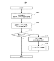
- FIG. 3 is a flowchart of the diagnostic process according to the first embodiment.
- FIG. 4 is a diagram illustrating a situation in the traveling direction of the host vehicle according to the first embodiment.
- FIG. 5 is a diagram for explaining a risk map and risk oversight according to the first embodiment.
- FIG. 6 is a flowchart of a diagnostic process according to a modification of the first embodiment.
- FIG. 7 is an overall configuration diagram of the vehicle control system according to the second embodiment.
- FIG. 8 is a flowchart of risk map extraction processing according to the second embodiment.
- FIG. 9 is a flowchart of a diagnostic process according to the second embodiment.
- FIG. 10 is an overall configuration diagram of a vehicle control system according to the third embodiment.
- FIG. 11 is a flowchart of the risk map extraction process according to the third embodiment.
- FIG. 12 is a flowchart of a diagnostic process according to the third embodiment.
- FIG. 13 is an overall configuration diagram of a vehicle control system according to a fourth embodiment.
- FIG. 14 is a functional configuration diagram of the vehicle control system according to the fourth embodiment.
- FIG. 15 is a diagram for explaining a missed risk list and a method for determining an abnormal ECU according to the fourth embodiment.
- FIG. 16 is a flowchart of a diagnostic process according to the fourth embodiment.
- FIG. 17 is a functional configuration diagram of the vehicle control system according to the fifth embodiment.
- FIG. 18 is a first system configuration diagram in the vehicle control system according to the fifth embodiment.
- FIG. 19 is a second system configuration diagram in the vehicle control system according to the fifth embodiment.
- FIG. 20 is an overall configuration diagram of the vehicle control system according to the sixth embodiment.
- FIG. 21 is a functional configuration diagram of the vehicle control system according to the sixth embodiment.
- FIG. 22 is an overall configuration diagram of the vehicle control system according to the seventh embodiment.
- FIG. 23 is a functional configuration diagram of the vehicle control system according to the seventh embodiment.
- FIG. 24 is a flowchart of a diagnostic process according to the seventh embodiment.
- the process may be described with “program” as the operation subject, but the program is executed by a processor (for example, a CPU (Central Processing Unit)) so that a predetermined process is appropriately performed.
- the processing subject may be a processor.
- the process described with the program as an operation subject may be performed by an apparatus including a processor. Further, a dedicated hardware circuit that performs part or all of the processing performed by the processor may be included.
- the computer program may be installed on the device from a program source.
- the program source may be, for example, a program distribution server or a non-transitory recording medium that can be read by a computer.
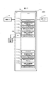
- FIG. 1 is an overall configuration diagram of a vehicle control system according to the first embodiment.
- a vehicle control system 1000 as an example of an abnormality diagnosis system is a system mounted on a vehicle such as an automobile, and includes various sensors 12, various actuators 13, a plurality of ECUs (electronic control units) 1A and 1B, and a reset. And an arbitration circuit 15.
- the ECU 1A and the ECU 1B are communicably connected via the in-vehicle network 14.
- the in-vehicle network 14 may be any communication network such as Ethernet (registered trademark) or CAN-FD (CAN with Flexible Data-Rate).
- Each ECU (1A, 1B) is connected with various sensors 12, various actuators 13, and a reset arbitration circuit 15.
- the various sensors 12 include one or more sensors for capturing information on the surrounding environment of the vehicle such as a radar, a camera, and a GPS sensor.
- the various sensors 12 may include a sensor for taking in map information and a sensor for taking in information on the vehicle such as the vehicle speed and the steering angle.
- Various sensors 12 output the detected sensor information to the ECU (1A, 1B).
- the various sensors 12 may output sensor information from a common sensor to the ECU 1A and the ECU 1B for all sensor information. For all sensor information, the sensors 1A and 1B may be different from sensors of different individuals having the same function.
- Sensor information may be output to each of the ECUs 1B, and only a part of the sensor information of the sensor information may be output from different sensors having the same function to each of the ECUs 1A and 1B. The remaining sensor information may be output from the common sensor to the ECU 1A and the ECU 1B.
- the various actuators 13 include one or more actuators for operating an accelerator, a brake, a steering, and the like for operating the vehicle.
- Various actuators 13 control traveling of the vehicle based on control information input from the ECU 1A or the ECU 1B.
- the ECU 1A (1B) includes a CPU 10A (10B) and a memory 11A (11B).
- the CPU 10A (10B) executes various processes in accordance with programs stored in the memory 11A (11B).
- the memory 11A (11B) is, for example, a RAM (RANDOM ACCESS MEMORY), and stores programs executed by the CPU 10A (10B) and necessary information.
- the memory 11A includes an object recognition / motion prediction program 111A (111B), a risk map creation program 112A (112B), a diagnosis (risk map comparison) program 113A (113B), a track generation / vehicle control program 114A (114B), The other system reset program 115A (115B) and the risk map 116A (116B) are stored. The function of each program will be described later.
- the program may be described as an operating entity for convenience, but the actual executing entity is the CPU (10A, 10B) that executes the program.
- each structure of ECU1A and ECU1B may be the same structure, or the same structure.
- the risk map (116A, 116B) is an example of risk information, and each point where the host vehicle (referred to as the host vehicle) can travel (for example, each point in front of the host vehicle when moving forward) and the host vehicle at that point. It is the map which represented on the plane corresponding with the value (risk level) which digitized the risk at the time of having existed.
- the reset arbitration circuit 15 receives a reset request (reset signal) from each ECU (1A, 1B) and performs a process of resetting the other ECU (other system).
- the reset arbitration circuit 15 receives a reset request from the other (ie, ECU 1B) after receiving a reset request from one (eg, ECU 1A) and before resetting the other (eg, ECU 1B). In this case, it is determined which ECU is to be reset according to a predetermined priority order, and the determined ECU is reset.
- FIG. 2 is a functional configuration diagram of the vehicle control system according to the first embodiment.
- FIG. 2 describes the functional configuration in the Data Flow Diagram format.
- the object recognition / motion prediction program (111A, 111B) (actually, a functional unit configured by the CPU (10A, 10B) that executes the object recognition / motion prediction program) receives sensor inputs (sensor information). ) Is recognized, an external object such as a preceding vehicle is recognized, and the movement of the object is predicted and output as object information.
- the risk map creation program (112A, 112B) (actually, a functional unit configured by the CPU (10A, 10B) executing the risk map creation program: an example of the risk information generation unit) is an object recognition / motion prediction program ( 111A, 111B) is used as an input to create a risk map (116A, 116B), and the risk map is sent to a diagnosis (risk map comparison) program (113A, 113B) of the ECU (own ECU) to which it belongs. And a risk map to the diagnosis (risk map comparison) program (113B, 113A) of the other ECU.
- the function unit configured by the CPU 10A that executes the risk map creation program 112A is the first risk information generation unit
- the function unit configured by the CPU 10B that executes the risk map creation program 112B generates the second risk information. Part.
- Diagnosis (risk map comparison) program (113A, 113B) (actually, a functional unit composed of CPUs (10A, 10B) executing a diagnosis (risk map comparison) program: an example of a diagnosis unit) is sent to another ECU.
- a risk map transmission request for requesting transmission of a risk map created by another ECU is transmitted via the in-vehicle network 14.
- the diagnosis (risk map comparison) program (113A, 113B) receives a risk map transmission request from another ECU via the in-vehicle network 14, the risk map transmission request source of the own ECU (10A) is obtained. To the other ECU (10B).
- the diagnosis (risk map comparison) program (113A, 113B) includes a risk map output from the risk map creation program (112A, 112B) of the own ECU and a diagnosis (risk map comparison) program (113B, 113A) of the other ECU. ) Is compared with the risk map obtained from), diagnoses whether there is an abnormality in the risk map (for example, whether there is no risk overlooked), and if there is an abnormality (in this case, there is a risk overlooked) ) Includes a reset requirement indicating that a handling process for an abnormality of the other ECU (other system) (abnormality handling process: for example, a process of resetting the ECU of the other system) is required, and the other system reset program (115A, 115B). ).
- the trajectory generation / vehicle control program (114A, 114B) (actually, a functional unit constituted by the CPU (10A, 10B) executing the trajectory generation / vehicle control program) is executed by the risk map creation program (112A, 112B) generates a track of the own vehicle from the risk map output, and generates and outputs control information for controlling the various actuators 13 so that the vehicle travels on the generated track.
- Other system reset program (115A, 115B) (actually, a functional unit composed of CPUs (10A, 10B) executing the other system reset program: an example of an abnormality handling processing unit) is a diagnostic (risk map comparison) program.
- a reset signal for resetting the other ECU is output to the reset arbitration circuit 15.
- Object recognition / motion prediction program (111A, 111B), risk map creation program (112A, 112B), diagnosis (risk map comparison) program (113A, 113B), track generation / vehicle control program (114A, 114B), and
- Each program of the other system reset program (115A, 115B) may be a program having the same code in the ECU 11A and the ECU 11B, and at least one of the programs has the same function but is different in configuration. Also good. For example, as a program having the same function but different configuration, for example, if the program is configured by performing learning, a program learned by using different data may be used. It is good also as a program created by. As described above, by using a program having the same function but different configuration between ECUs, a problem in one program can be covered by the other program, and the reliability as a whole is improved. Can do.
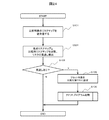
- FIG. 3 is a flowchart of the diagnostic process according to the first embodiment.
- the diagnosis process is executed by the CPU (10A, 10B) executing the diagnosis (risk map comparison) program (113A, 113B).
- the diagnosis process is executed, for example, with a period of time (relatively short time) when the response does not become a problem even if an abnormality occurs.
- the processing of the ECU 1A diagnosis (risk map comparison) program 113A will be mainly described, but the processing of the ECU 1B diagnosis (risk map comparison) program 113B is also the same.
- the diagnosis (risk map comparison) program 113A transmits / receives a risk map to / from another ECU (ECU 1B) (step S101).
- the diagnosis (risk map comparison) program 113A transmits a risk map transmission request to the ECU 1B via the in-vehicle network 14.
- the diagnosis (risk map comparison) program 113B of the ECU 1B transmits the risk map created by the ECU 1B to the diagnosis (risk map comparison) program 113A via the in-vehicle network 14.
- the diagnosis (risk map comparison) program 113A acquires the risk map created by the other ECU (ECU 1B) as a comparison risk map.
- a risk map transmission program that transmits a risk map according to a risk map transmission request may be provided separately from the diagnosis (risk map comparison) program 113B.
- the diagnosis (risk map comparison) program 113A and the diagnosis (risk map comparison) program 113B do not need to wait for each other in step S101.
- the diagnosis (risk map comparison) program 113A compares the risk map generated by the ECU 1A with the acquired risk map generated by the ECU 1B, and whether or not there is an oversight of the risk in the risk map generated by the ECU 1B. Is detected (step S102).
- missed risk means that one risk map exists as a risk (or has a high risk), but other risk maps do not have a risk (or a low risk). It means that it is said.
- step S103 when it is detected that there is an oversight of the risk (step S103: Y), the diagnosis (risk map comparison) program 113A resets another ECU (in this case, ECU 1B) that is the comparison target as the reset target.
- a key is generated (step S105), the other system reset program 115A is started, the reset is passed (step S106), and the process is terminated.
- the activated other system reset program 115 ⁇ / b> A transmits a reset signal for resetting the other ECU to the reset arbitration circuit 15 based on the reset requirement.
- the reset arbitration circuit 15 that has received the reset signal executes a process of resetting the ECU based on the received reset signal.
- step S103 N
- diagnosis (risk map comparison) program 113A ends the process.
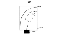
- FIG. 4 is a diagram showing a situation in the traveling direction of the host vehicle according to the first embodiment.
- the host vehicle 401 is about to enter a right curve separated by a shoulder 402 and a center line 403, and a preceding vehicle 404 is traveling in front of the host vehicle 401. .
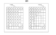
- FIG. 5 is a diagram for explaining the risk map and risk oversight according to the first embodiment.
- risk map 116A shows an example of a risk map generated by ECU 1A in the situation shown in FIG. 4
- risk map 116B shows an example of a risk map generated by ECU 1B in the situation shown in FIG.
- each square corresponds to the respective position in FIG. 4, and the risk level when the own vehicle 401 enters the position is set in the square.
- the In the present embodiment, the risk level is a value from 0 (minimum) to 9 (maximum). In FIG. 5, the risk level of 0 is omitted and omitted.
- the position outside the road shoulder 402 (upper left in the drawing) is set to the risk level 9 because it cannot travel, and the risk level 8 to 9 is set outside the center line 403 (lower right in the drawing). Is set. Further, since there is a risk of contacting the own vehicle 401 when the preceding vehicle 404 decelerates, the position of the preceding vehicle 404 and its surrounding positions are set to risk levels 3-6. The risk level for each position is set by the risk map creation program 112A.
- the risk map 116B the position of the preceding vehicle 404 and its surrounding positions are at the risk level 0 (the square portion on the dotted line).
- the risk maps 116A and 116B are normal, they should be the same or substantially the same, but if any abnormality occurs, they become different states.
- the diagnosis (risk map comparison) program 113A misses the risk of the squares on the dotted line by comparing the risk maps. Is determined. That is, the CPU 10A executing the diagnosis (risk map comparison) program 113A diagnoses that an abnormality has occurred in the risk map 116B generated by the ECU 1B.
- any of the elements involved in the generation of the risk map 116B (for example, a sensor that inputs sensor information to the ECU 1B, the object recognition / motion prediction program 111B, the risk map generation program 112B, or the ECU 1B itself) ) Has occurred, and there is a possibility that appropriate automatic control will not be performed if this condition remains unchanged.
- the determination of whether or not the risk is missed is, for example, determining that the risk is missed when the risk level of one of the squares indicating the same position is 0 and the other risk level is not 0. Also good.
- step S102 when a missed risk is detected in step S102 and there is a missed risk in the risk map created by another ECU, reset to the other ECU that missed the risk in steps S105 and S106. Can be applied.
- a risk map that misses a risk can be detected appropriately, vehicle control based on this risk map can be appropriately prevented, and safety in driving control can be improved.
- the value of the square of one risk map corresponding to the same position is 0, and the square of the other risk map
- the following diagnostic process may be executed.
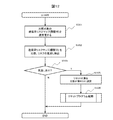
- FIG. 6 is a flowchart of a diagnostic process according to a modification of the first embodiment.
- the same parts as those in the diagnosis process of FIG. 3 are denoted by the same reference numerals, and redundant description is omitted.
- step S103 includes step S109 after N, and includes step S107 and step S108 between Y in step S103 and step S105.
- step S103 When it is determined in step S103 that there is an oversight (step S103: Y), the diagnosis (risk map comparison) program 113A counts up the number of times (the number of determinations) determined to be overlooked from a predetermined time point (add 1). (Step S107), it is determined whether or not the number of determinations is equal to or greater than a certain number (Step S108). As a result, when the number of determinations is not equal to or greater than the predetermined number (step S108: N), the diagnosis (risk map comparison) program 113A performs processing without executing subsequent processing (steps S105 and S106) for resetting other ECUs. Exit.
- step S108: Y when the number of determinations is equal to or greater than a certain number (step S108: Y), the diagnosis (risk map comparison) program 113A executes subsequent processing (steps S105 and S106) for resetting the other ECUs. If it is not determined that there is an oversight (step S103: N), it means that there is no abnormality, so the diagnosis (risk map comparison) program 113A clears the number of determinations to 0 (step S109). The process is terminated.
- the object recognition / motion prediction program (111A, 111B) is executed as one program, and is executed in the ECU (1A, 1B) that executes the risk map creation program (112A, 112B).
- the present invention is not limited to this.
- the object recognition / motion prediction program (111A, 111B) may be divided into a plurality of programs, and may be executed by another ECU or a plurality of ECUs. Also good.
- the track generation / vehicle control program (114A, 114B) may be divided into a plurality of programs, or may be executed by another ECU or a plurality of ECUs.
- FIG. 7 is an overall configuration diagram of the vehicle control system according to the second embodiment.
- the memory (11A, 11B) further includes a transmission risk map (117A, 117B: an example of a partial risk map), compared to the vehicle control system 1000 according to the first embodiment.
- a transmission risk map (117A, 117B: an example of a partial risk map)
- This is a vehicle control system in which a risk map comparison condition (static) (118A, 118B) and a risk map extraction program (119A, 119B) are stored.
- the function unit configured by the CPU (10A, 10B) executing the risk map extraction program (119A, 119B) is an example of the extraction unit.
- the transmission risk map (117A, 117B) is a risk map transmitted in accordance with a risk map transmission request from another ECU, and some information extracted from the risk map (116A, 116B) (partial coordinates of the risk map) , A set of coordinates and risk levels corresponding to the coordinates).
- Risk map comparison condition (static) (118A, 118B) is a condition for extracting the transmission risk map (117A, 117B) from the risk map (116A, 116B).
- the risk map comparison condition (static) (117A, 117B) is, for example, that the risk level is equal to or higher than a certain threshold (high risk condition), and that the distance from the position of the own vehicle is equal to or less than a certain (close order condition) ), The risk level is high with respect to the front, rear, left, and right positions (neighboring comparison conditions).
- each risk level of a position corresponding to a high risk condition and a position corresponding to a close order condition is weighted and added for each position.
- the result may be a position belonging to the top N (N is an arbitrary integer).
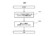
- FIG. 8 is a flowchart of risk map extraction processing according to the second embodiment.
- the risk map extraction process is executed by the CPU (10A, 10B) executing the risk map extraction program (119A, 119B).
- the risk map extraction process is executed, for example, before executing the diagnosis process.
- the process of the risk map extraction program 119A of the ECU 1A will be described, but the process of the risk map extraction program 119B of the ECU 1B is the same.
- the risk map extraction program 119A refers to the risk map (116A, 116B), extracts information that matches the risk map comparison condition (117A, 117B) (step S201), and uses the extracted information as a transmission risk map (118A, 118B) (step S202).
- FIG. 9 is a flowchart of the diagnosis process according to the second embodiment.
- parts similar to those in the diagnostic process according to the first embodiment are denoted by the same reference numerals, and redundant description is omitted.
- the diagnosis (risk map comparison) program 113A transmits and receives the transmission risk map 117B of the other ECU (ECU 1B) as a comparison target risk map (step S301).
- the diagnosis (risk map comparison) program 113A transmits a risk map transmission request to the ECU 1B via the in-vehicle network 14.
- the diagnosis (risk map comparison) program 113B of the ECU 1B transmits the transmission risk map 117B created by the ECU 1B to the diagnosis (risk map comparison) program 113A via the in-vehicle network 14.
- the functional unit configured by the CPU (10A, 10B) executing the diagnosis (risk map comparison) program (113A, 113B) is an example of the transmission unit.
- the diagnosis (risk map comparison) program 113A compares the transmission risk map 117A generated by the ECU 1A with the transmission risk map 117B generated by the acquired ECU 1B, and the transmission risk map created by the ECU 1B. It is detected whether or not there is a risk oversight (step S302).
- the subsequent processing is the same as the diagnostic processing according to the first embodiment.
- the transmission risk map 117B having a data amount smaller than that of the risk map 116B is transmitted via the in-vehicle network 14, so that the communication time can be shortened and the load on the in-vehicle network 14 is reduced. Can do. Further, in the risk map comparison process in step S302, the number of positions to be compared is small, so that the processing time can be shortened and the processing load on the ECU can be reduced.
- FIG. 10 is an overall configuration diagram of the vehicle control system according to the third embodiment.
- the vehicle control system 1002 according to the third embodiment is different from the vehicle control system 1001 according to the second embodiment in that a risk map comparison condition (static) is used instead of the risk map comparison condition (static) (118A, 118B).
- a risk map comparison condition static
- (Dynamic) 140A, 140B)
- the transmission risk map 117A, 117B
- a transmission risk map with history
- a risk map extraction program 119A, 119B
- Risk map comparison condition (static / dynamic) (140A, 140B) is a condition for extracting the transmission risk map (with history) (141A, 142B) from the risk map (116A, 116B).
- the risk map comparison condition (static / dynamic) (140A, 140B) includes the same condition as the risk map comparison condition (static) (118A, 118B) as a static condition, and further includes a risk map comparison condition (dynamic). Included).
- the risk map comparison condition (dynamic) is a condition that is applied based on the history of the results detected in the risk map comparison condition (static), and the approach speed (the movement speed of the corresponding risk) is a certain level or higher. There is a novelty of appearance (not detected in the latest extraction of a certain number of times or less).
- FIG. 11 is a flowchart of risk map extraction processing according to the third embodiment.
- the risk map extraction process is executed by the CPU (10A, 10B) executing the risk map extraction program (142A, 142B).
- the risk map extraction process is executed, for example, before executing the diagnosis process.
- the risk map extraction program 142A refers to the risk map (116A, 116B), extracts information of each corresponding coordinate according to the static condition of the risk map comparison condition (dynamic / static) (140A, 140B), Thereafter, for the history of each coordinate information extracted by the static condition, the information of each corresponding coordinate is extracted according to the dynamic condition (step S211), the history of the information extracted by the dynamic condition, The information extracted by the dynamic condition is output to the transmission risk map (with history) (141A, 141B) (step S212).
- This risk map extraction process can create a transmission risk map that is focused on coordinates considered to be more important, and can further reduce the amount of data in the transmission risk map.
- FIG. 12 is a flowchart of the diagnostic process according to the third embodiment.
- parts similar to those in the diagnosis process according to the first embodiment are denoted by the same reference numerals, and redundant description is omitted.
- the diagnosis (risk map comparison) program 113A transmits and receives the transmission risk map detected by the dynamic condition in the transmission risk map (with history) 141B of the other ECU (ECU 1B) as a risk map to be compared (step) S351).
- the diagnosis (risk map comparison) program 113A transmits a risk map transmission request to the ECU 1B via the in-vehicle network 14.
- the diagnosis (risk map comparison) program 113B of the ECU 1B diagnoses the transmission risk map detected by the dynamic condition of the transmission risk map (with history) 141B created by the ECU 1B via the in-vehicle network 14. (Risk map comparison) This is transmitted to the program 113A.
- the diagnosis (risk map comparison) program 113A includes the transmission risk map detected by the dynamic condition in the transmission risk map (with history) 141A generated by the ECU 1A and the transmission generated by the acquired ECU 1B. Compare with the transmission risk map detected by the dynamic condition in the credit risk map (with history) 141B, and overlook the risk in the transmission risk map of the transmission risk map (with history) 141B created by the ECU 1B It is determined whether or not there is (step S352). The subsequent processing is the same as the diagnostic processing according to the first embodiment.
- the transmission risk map detected by the dynamic condition in the transmission risk map (with history) 141B having a smaller data amount than the transmission risk map 117B is transmitted via the in-vehicle network 14. Therefore, the communication time can be shortened and the load on the in-vehicle network 14 can be reduced.
- the risk map comparison process in step S352 since there are fewer positions to compare, the processing time can be shortened and the processing load can be reduced.
- FIG. 13 is an overall configuration diagram of the vehicle control system according to the fourth embodiment.
- the vehicle control system 1003 according to the fourth embodiment is further provided with an ECU 1C with respect to the vehicle control system 1000 according to the first embodiment, and memory (11A, 11B) of each ECU (1A, 1B, 1C). , 11C) further stores the missed risk list (143A, 143B, 143C), and changes the processing of the diagnosis (risk map comparison) program (113A, 113B, 113C).
- the ECU 1C has the same configuration as the ECU 1A. The following description will focus on differences from the vehicle control system 1000 according to the first embodiment.
- FIG. 14 is a functional configuration diagram of the vehicle control system according to the fourth embodiment.
- the functional configuration of the vehicle control system 1003 according to the fourth embodiment is a functional configuration further including the configuration of the ECU 1C having the same configuration as the ECU 1A with respect to the functional configuration of the vehicle control system 1000 according to the first embodiment.
- risk map 116A created by risk map creation program 112A of ECU 1A is transmitted to diagnosis (risk map comparison) program 113B of ECU 1B and created by risk map creation program 112B of ECU 1B.
- the risk map 116B is transmitted to the diagnosis (risk map comparison) program 113C of the ECU 1C
- the risk map 116C created by the risk map creation program 112C of the ECU 1C is transmitted to the diagnosis (risk map comparison) program 113A of the ECU 1A.
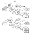
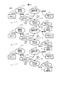
- FIG. 15 is a diagram for explaining a missed risk list and a method for determining an abnormal ECU according to the fourth embodiment.
- the missed risk lists 143A, 143B, and 143C each correspond to one row shown in FIG. 15, and information on the diagnosed ECU, information indicating the comparison source risk map, information indicating the comparison target risk map, and missed information Information on the determination result.
- the diagnosis (risk map comparison) program 113A of the ECU 1A compares the ECU 1A and the risk map of the ECU 1C to determine whether or not there is an oversight. Further, the diagnosis (risk map comparison) program 113A of the ECU 1A acquires a missed risk list that is a determination result of the missed risk from the other ECUs 1B and 1C. Next, the ECU 1A diagnosis (risk map comparison) program 113A determines an abnormal ECU (an ECU to be reset) based on its own determination result and the missed risk list from the other ECUs 1B and 1C.
- the ECU 1A determines that the comparison target ECU (ECU 1C) is overlooked, and the other ECUs 1B and 1C determine that the comparison target ECU does not miss.
- the diagnosis (risk map comparison) program 113A determines that only the ECU 1A has missed based on its own determination result and the missed risk list from the other ECUs 1B and 1C, and the ECU 1A as a minority is abnormal.
- the ECU 1B diagnosis (risk map comparison) program 113B determines that only the ECU 1A has missed based on its own determination result and the missed risk list from the other ECUs 1A and 1C.
- the ECU 1A as a minority can be determined to be abnormal, and the diagnosis (risk map) of the ECU 1C can be determined.
- the comparison) program 113C determines that only the ECU 1A has missed based on its own judgment result and the missed risk list from the other ECUs 1A and 1B, and can determine that the minority ECU 1A is abnormal. . If the number of ECUs is four or more, a missed risk list of other ECUs is obtained, and a certain number of ECUs reporting that there is a miss based on their own determination results and the missed risk list of other ECUs. In the following cases, these ECUs reported as overlooked may be reset.
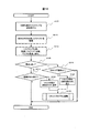
- FIG. 16 is a flowchart of diagnostic processing according to the fourth embodiment.
- the same parts as those in the diagnostic process according to the first embodiment are denoted by the same reference numerals, and redundant description is omitted.
- FIG. 16 illustrates the processing of the ECU 1A, but similar processing is also executed in the ECU 1B and ECU 1C.
- the diagnosis (risk map comparison) program 113A acquires the risk list of the other ECU (ECU 1B) (step S312).
- the diagnosis (risk map comparison) program 113A transmits a missed risk list transmission request to the other ECUs (ECU 1B, ECU 1C) via the in-vehicle network 14.
- the diagnosis (risk map comparison) program (113B, 113C) of another ECU transmits the missed risk list created by the ECU (1B, 1C) via the in-vehicle network 14.
- the diagnosis (risk map comparison) program 113A compares the risk map 116A generated by the ECU 1A with the acquired risk map 116C and the risk map 116C created by the ECU 1C misses the risk. It is detected whether or not there is, and by referring to the contents of the detection result and the acquired missed risk list, an ECU having a missed risk is detected (step S313).
- step S103 If it is determined in step S103 that there is an oversight of risk (S103: Y), the diagnosis (risk map comparison) program 113A has detected that the ECU is overdetected (determination that the risk is overlooked is a minority). If it is determined whether or not the own ECU is overdetected (step S315: Y), the process is terminated without setting the other ECU as a reset target, while the own ECU is not overdetected. In (Step S315: N), the process proceeds to Step S105, and resetting of other ECUs that missed the risk is advanced.
- step S103 determines whether or not there is an ECU (step S314). If it is determined that there is another ECU for overdetection (step S314: Y), the diagnosis (risk map comparison) program 113A selects the other ECU for overdetection. The reset necessity set as the reset target is generated (step S316), and the process proceeds to step S106. On the other hand, if it is determined that there is no other ECU with overdetection (step S314: N), the other ECU is not set as the reset target. The process ends.
- the ECU having the risk map creation program that has detected over-detection among a plurality of ECUs is the reset target.
- FIG. 17 is an overall configuration diagram of a vehicle control system according to the fifth embodiment.
- the vehicle control system 1004 is a vehicle control system in which the functions executed by the two ECUs 1A and 1B in the vehicle control system 1000 according to the first embodiment are realized by one ECU 1A. That is, the memory 11A of the ECU 1A includes object recognition / motion prediction programs 111A and 111B, risk map creation programs 112A and 112B, diagnosis (risk map comparison) programs 113A and 113B, track generation / vehicle control programs 114A and 114B, and other systems. The reset programs 115A and 115B and the risk maps 116A and 116B are stored.
- the other system reset programs 115A and 115B of this embodiment reset each program of the other system to the reset arbitration circuit 15 when receiving the reset necessity output from the diagnosis (risk map comparison) program (113A and 113B). A reset signal is output.
- the reset arbitration circuit 15 performs control to reset (restart) each other program in accordance with the reset signal.
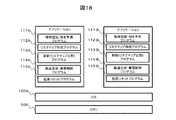
- FIG. 18 is a first system configuration diagram in the vehicle control system according to the fifth embodiment.
- FIG. 19 is a second system configuration diagram in the vehicle control system according to the fifth embodiment.
- the vehicle control system 1004 has an OS 120A operating on the CPU 10A.
- the first control system in which the applications of the vehicle control program 114A and the other system reset program 115A operate is configured, the object recognition / motion prediction program 111B, the risk map creation program 112B, the diagnosis (risk map comparison) program 113B, the track It can be set as the system configuration which constitutes the 2nd control system in which the application of generation / vehicle control program 114B and other system reset program 115B operates.
- the hypervisor 121A that enables the virtual computer to operate is operated on the CPU 10A
- the virtual CPUs 122A and 122B are constructed on the hypervisor 121A
- the OS 123A is operated on the virtual CPU 122A.
- the applications of the object recognition / motion prediction program 111A, the risk map creation program 112A, the diagnosis (risk map comparison) program 113A, the trajectory generation / vehicle control program 114A, and the other system reset program 115A run on the OS 123A.
- the OS 123B is operated on the virtual CPU 122B together with the configuration of the first control system, and the object recognition / motion prediction program 111B and the risk map creation program 112B are executed on the OS 123B.
- Diagnosis (risk maps Comparative) program 113B, by trajectory generator, the vehicle control program 114B, and the other system reset program 115B application operates, may be a system configuration which constitutes the second control system.
- the vehicle control system 1004 it is possible to appropriately detect that an abnormality (for example, an oversight of a risk) has occurred in one of a plurality of systems that operate on one ECU. Can be reset.
- an abnormality for example, an oversight of a risk
- FIG. 20 is an overall configuration diagram of the vehicle control system according to the sixth embodiment.
- the vehicle control system 1005 has a memory (11A, 11B: an example of a pseudo sensor information storage unit) and a pseudo sensor input (143A, 143B :) compared to the vehicle control system 1000 according to the first embodiment. (Pseudo sensor information) is stored, and a program such as an object recognition / motion prediction program (111A, 111B) executes processing using this pseudo sensor input.
- the diagnosis process using the pseudo sensor input is executed, for example, when the vehicle is started or when the vehicle is stopped.
- the pseudo sensor inputs (143A, 143B) are pseudo sensor inputs (sensor information) that are assumed to be input from various sensors 12 when the vehicle is in a certain situation.
- FIG. 21 is a functional configuration diagram of the vehicle control system according to the sixth embodiment.
- FIG. 21 describes the functional configuration in the Data Flow Diagram format.
- the object recognition / motion prediction program (111A, 111B) (actually, a functional unit configured by the CPU (10A, 10B) executing the object recognition / motion prediction program) executes a diagnosis process using a pseudo sensor input.
- the pseudo sensor input of the memory (11A, 11B) is received, an external object such as a preceding vehicle in the situation indicated by the pseudo sensor is recognized, and the movement of the object is predicted and output as object information. .
- the risk map creation program (112A, 112B) (actually, a functional unit configured by the CPU (10A, 10B) executing the risk map creation program) is output by the object recognition / motion prediction program (111A, 111B).
- the object information is used as an input to create a risk map (116A, 116B) and output the risk map to the diagnosis (risk map comparison) program (113A, 113B) of the ECU to which the user belongs (113A, 113B).
- the risk map is output to the ECU diagnosis (risk map comparison) program (113B, 113A).
- Diagnosis (risk map comparison) program (113A, 113B) (actually, a functional unit composed of CPUs (10A, 10B) executing the diagnosis (risk map comparison) program) is connected to the in-vehicle network 14 with respect to other ECUs.
- a risk map transmission request for requesting transmission of a risk map created by another ECU is transmitted via
- the diagnosis (risk map comparison) program (113A, 113B) receives a risk map transmission request from another ECU via the in-vehicle network 14, the risk map transmission request source of the own ECU (10A) is obtained. To the other ECU (10B).
- the diagnosis (risk map comparison) program (113A, 113B) is based on the risk map based on the pseudo sensor input output from the diagnosis (risk map comparison) program of the own ECU and the diagnosis (risk map comparison) program of the other ECU. It compares with the risk map based on the acquired pseudo sensor input, detects whether or not there is a missed risk, and if there is a missed risk, it indicates that it is necessary to reset the other ECU (other system) The reset request is output to the other system reset program (115A, 115B).
- the vehicle control system 1005 can appropriately detect an abnormality in the risk map when the vehicle is started or when the vehicle is stopped. In addition, since the risk map is created based on the pseudo sensor input, it is not affected by the abnormality in the various sensors 12.
- FIG. 22 is an overall configuration diagram of the vehicle control system according to the seventh embodiment.
- the memory (11A, 11B) further stores a comparison risk map (144A, 144B) with respect to the vehicle control system 1005 according to the sixth embodiment.
- the (risk map comparison) program (113A, 113B) is a vehicle control system that performs diagnosis using a comparative risk map.
- the comparison risk map (144A, 144B) is a risk map to be created when there is a pseudo sensor input.
- FIG. 23 is a functional configuration diagram of the vehicle control system according to the seventh embodiment.
- FIG. 23 describes the functional configuration in the Data Flow Diagram format.
- the risk map creation program (112A, 112B) (actually, a functional unit configured by the CPU (10A, 10B) executing the risk map creation program) is output by the object recognition / motion prediction program (111A, 111B).
- the object information is input to create a risk map (116A, 116B) and output the risk map to the diagnosis (risk map comparison) program (113B, 113A) of the other ECU.
- Diagnosis (risk map comparison) program (113A, 113B) (actually, a functional unit composed of CPUs (10A, 10B) executing the diagnosis (risk map comparison) program) is connected to the in-vehicle network 14 with respect to another ECU.
- a risk map transmission request for requesting transmission of a risk map created by another ECU is transmitted via
- the diagnosis (risk map comparison) program (113A, 113B) receives a risk map transmission request from another ECU via the in-vehicle network 14, the risk map transmission request source of the own ECU (10A) is obtained. To the other ECU (10B).
- the diagnosis (risk map comparison) program (113A, 113B) includes a comparison risk map (144A, 144B) in the memory (11A, 11B) and a diagnosis (risk map comparison) program (113B, 113A) of the other ECU.
- a comparison risk map 144A, 144B
- a diagnosis (risk map comparison) program 113B, 113A
- the necessary reset is output to the other system reset program (115A, 115B).
- FIG. 24 is a flowchart of the diagnostic process according to the seventh embodiment.
- the same parts as those in the diagnosis process according to the first embodiment are denoted by the same reference numerals, and redundant description is omitted.
- the diagnosis (risk map comparison) program 113A compares the comparison risk map 144A in the memory 11A with the acquired risk map 116B generated by the ECU 1B, and whether or not there is a risk overlook in the risk map created by the ECU 1B. Is detected (step S321).
- the subsequent processing is the same as the diagnostic processing according to the first embodiment.
- an accurate comparison risk map corresponding to a pre-stored pseudo sensor input is compared with a risk map acquired from another ECU, so that an abnormality in the risk map is detected.
- the reliability of can be increased.
- any one of the above embodiments may be combined.
- the created risk map is transmitted to another ECU.
- You may make it transmit a risk map.
- the ECU is reset as the abnormality handling process.
- the present invention is not limited to this, and the operation of the ECU may be stopped, for example.
- part or all of the processing performed by the CPU may be performed by a dedicated hardware circuit.
- the program in the above embodiment may be installed from a program source.
- the program source may be a program distribution server or a storage medium (for example, a portable storage medium).
Landscapes
- Engineering & Computer Science (AREA)
- Automation & Control Theory (AREA)
- Transportation (AREA)
- Mechanical Engineering (AREA)
- Human Computer Interaction (AREA)
- Physics & Mathematics (AREA)
- General Physics & Mathematics (AREA)
- Mathematical Physics (AREA)
- Traffic Control Systems (AREA)
- Control Of Driving Devices And Active Controlling Of Vehicle (AREA)
Abstract
La présente invention permet de diagnostiquer facilement et de manière appropriée une anomalie liée à une commande de conduite automatique d'un véhicule. Dans un système de commande de véhicule (1000), la présente invention est configurée pour être dotée : d'une pluralité d'unités de génération d'informations de risque (CPU 10A, 10B pour exécuter des programmes de construction de carte du risque 112A, 112B) qui génèrent, sur la base d'informations de capteur sur un objet autour du véhicule, des informations de risque sur un risque au moment du déplacement du véhicule devant être utilisées pour une commande de conduite automatique du véhicule ; et d'une unité de diagnostic (CPU 10A, 10B pour exécuter des programmes de diagnostic (comparaison de carte du risque) 113A, 113B) qui diagnostique si oui ou non une anomalie se produit dans les informations de risque générées sur la base d'une pluralité d'informations de risque générées par la pluralité d'unités de génération d'informations de risque.
Priority Applications (3)
| Application Number | Priority Date | Filing Date | Title |
|---|---|---|---|
| US16/961,288 US20210070321A1 (en) | 2018-03-13 | 2019-03-04 | Abnormality diagnosis system and abnormality diagnosis method |
| EP19766957.5A EP3766753B1 (fr) | 2018-03-13 | 2019-03-04 | Système de diagnostic d'anomalie et procédé de diagnostic d'anomalie |
| JP2020506405A JP6922072B2 (ja) | 2018-03-13 | 2019-03-04 | 異常診断システム及び異常診断方法 |
Applications Claiming Priority (2)
| Application Number | Priority Date | Filing Date | Title |
|---|---|---|---|
| JP2018045736 | 2018-03-13 | ||
| JP2018-045736 | 2018-03-13 |
Publications (1)
| Publication Number | Publication Date |
|---|---|
| WO2019176603A1 true WO2019176603A1 (fr) | 2019-09-19 |
Family
ID=67906991
Family Applications (1)
| Application Number | Title | Priority Date | Filing Date |
|---|---|---|---|
| PCT/JP2019/008271 Ceased WO2019176603A1 (fr) | 2018-03-13 | 2019-03-04 | Système de diagnostic d'anomalie et procédé de diagnostic d'anomalie |
Country Status (4)
| Country | Link |
|---|---|
| US (1) | US20210070321A1 (fr) |
| EP (1) | EP3766753B1 (fr) |
| JP (1) | JP6922072B2 (fr) |
| WO (1) | WO2019176603A1 (fr) |
Cited By (1)
| Publication number | Priority date | Publication date | Assignee | Title |
|---|---|---|---|---|
| KR20220052163A (ko) * | 2020-10-20 | 2022-04-27 | 주식회사 에이치엘클레무브 | 전자 제어 장치 및 방법 |
Families Citing this family (12)
| Publication number | Priority date | Publication date | Assignee | Title |
|---|---|---|---|---|
| US11538287B2 (en) * | 2019-09-20 | 2022-12-27 | Sonatus, Inc. | System, method, and apparatus for managing vehicle data collection |
| EP3999979A4 (fr) | 2019-09-20 | 2023-07-26 | Sonatus, Inc. | Système, procédé et appareil de commande de communications extravéhiculaires |
| US12261747B2 (en) * | 2019-09-20 | 2025-03-25 | Sonatus, Inc. | System, method, and apparatus to execute vehicle communications using a zonal architecture |
| US12103479B2 (en) * | 2020-03-06 | 2024-10-01 | Sonatus, Inc. | System, method, and apparatus for managing vehicle automation |
| US12094259B2 (en) | 2020-03-06 | 2024-09-17 | Sonatus, Inc. | System, method, and apparatus for managing vehicle automation |
| US12573245B2 (en) | 2020-03-06 | 2026-03-10 | Sonatus, Inc. | System, method, and apparatus for managing vehicle automation |
| US12211323B2 (en) | 2020-03-06 | 2025-01-28 | Sonatus, Inc. | System, method, and apparatus for managing vehicle automation |
| US12528442B2 (en) * | 2020-03-06 | 2026-01-20 | Sonatus, Inc. | System, method, and apparatus for managing vehicle data collection |
| US12403921B2 (en) | 2020-03-06 | 2025-09-02 | Sonatus, Inc. | System, method, and apparatus for managing vehicle automation |
| US11772583B2 (en) | 2020-03-06 | 2023-10-03 | Sonatus, Inc. | System, method, and apparatus for managing vehicle automation |
| IL295313A (en) * | 2020-05-21 | 2022-10-01 | High Sec Labs Ltd | System and method for detection and prevention of cyber attacks at in-vehicle networks |
| KR102899314B1 (ko) * | 2020-08-27 | 2025-12-12 | 주식회사 에이치엘클레무브 | Mcu 고장 검출 장치 및 방법 |
Citations (4)
| Publication number | Priority date | Publication date | Assignee | Title |
|---|---|---|---|---|
| JP2008225786A (ja) * | 2007-03-12 | 2008-09-25 | Toyota Motor Corp | 道路状況検出システム |
| JP2016038689A (ja) * | 2014-08-07 | 2016-03-22 | 日立オートモティブシステムズ株式会社 | 行動計画装置 |
| JP2017196965A (ja) | 2016-04-26 | 2017-11-02 | 三菱電機株式会社 | 自動運転制御装置および自動運転制御方法 |
| JP2017224237A (ja) * | 2016-06-17 | 2017-12-21 | 日立オートモティブシステムズ株式会社 | 周辺環境認識装置 |
Family Cites Families (8)
| Publication number | Priority date | Publication date | Assignee | Title |
|---|---|---|---|---|
| JP3577765B2 (ja) * | 1995-02-15 | 2004-10-13 | 日産自動車株式会社 | 車両盗難防止装置の検査装置 |
| JP4887980B2 (ja) * | 2005-11-09 | 2012-02-29 | 日産自動車株式会社 | 車両用運転操作補助装置および車両用運転操作補助装置を備えた車両 |
| DE102011108292A1 (de) * | 2011-07-21 | 2012-04-05 | Daimler Ag | Verfahren zum Betrieb einer Fahrerassistenzvorrichtung |
| DE102012201653B4 (de) * | 2012-02-03 | 2024-05-29 | Bayerische Motoren Werke Aktiengesellschaft | Schaltungsanordnung in einem elektronischen Steuergerät eines Kraftfahrzeuges zur Erkennung von Fehlern |
| DE102015201569A1 (de) * | 2015-01-29 | 2016-08-04 | Continental Teves Ag & Co. Ohg | Fahrzeugsteuervorrichtung und verfahren |
| JP6803657B2 (ja) * | 2015-08-31 | 2020-12-23 | 日立オートモティブシステムズ株式会社 | 車両制御装置および車両制御システム |
| DE102016210984A1 (de) * | 2016-06-20 | 2017-12-21 | Robert Bosch Gmbh | Verfahren zum Betreiben eines Steuergeräts |
| DE102017010716A1 (de) * | 2017-11-10 | 2019-05-16 | Knorr-Bremse Systeme für Nutzfahrzeuge GmbH | System zum wenigstens teilautonomen Betrieb eines Kraftfahrzeugs mit doppelter Redundanz |
-
2019
- 2019-03-04 WO PCT/JP2019/008271 patent/WO2019176603A1/fr not_active Ceased
- 2019-03-04 EP EP19766957.5A patent/EP3766753B1/fr active Active
- 2019-03-04 US US16/961,288 patent/US20210070321A1/en not_active Abandoned
- 2019-03-04 JP JP2020506405A patent/JP6922072B2/ja active Active
Patent Citations (4)
| Publication number | Priority date | Publication date | Assignee | Title |
|---|---|---|---|---|
| JP2008225786A (ja) * | 2007-03-12 | 2008-09-25 | Toyota Motor Corp | 道路状況検出システム |
| JP2016038689A (ja) * | 2014-08-07 | 2016-03-22 | 日立オートモティブシステムズ株式会社 | 行動計画装置 |
| JP2017196965A (ja) | 2016-04-26 | 2017-11-02 | 三菱電機株式会社 | 自動運転制御装置および自動運転制御方法 |
| JP2017224237A (ja) * | 2016-06-17 | 2017-12-21 | 日立オートモティブシステムズ株式会社 | 周辺環境認識装置 |
Non-Patent Citations (1)
| Title |
|---|
| See also references of EP3766753A4 |
Cited By (3)
| Publication number | Priority date | Publication date | Assignee | Title |
|---|---|---|---|---|
| KR20220052163A (ko) * | 2020-10-20 | 2022-04-27 | 주식회사 에이치엘클레무브 | 전자 제어 장치 및 방법 |
| KR102844295B1 (ko) | 2020-10-20 | 2025-08-12 | 주식회사 에이치엘클레무브 | 전자 제어 장치 및 방법 |
| US12565222B2 (en) | 2020-10-20 | 2026-03-03 | Hl Klemove Corp. | Electronic control system, device, and method |
Also Published As
| Publication number | Publication date |
|---|---|
| JPWO2019176603A1 (ja) | 2020-12-17 |
| US20210070321A1 (en) | 2021-03-11 |
| EP3766753B1 (fr) | 2023-07-12 |
| EP3766753A4 (fr) | 2021-12-08 |
| JP6922072B2 (ja) | 2021-08-18 |
| EP3766753A1 (fr) | 2021-01-20 |
Similar Documents
| Publication | Publication Date | Title |
|---|---|---|
| JP6922072B2 (ja) | 異常診断システム及び異常診断方法 | |
| JP7430735B2 (ja) | 画像誤分類のためのセーフティモニタ | |
| US20210163024A1 (en) | Determination of Reliability of Vehicle Control Commands using a Voting Mechanism | |
| Stocco et al. | Confidence‐driven weighted retraining for predicting safety‐critical failures in autonomous driving systems | |
| US20210146939A1 (en) | Device and method for controlling a vehicle module | |
| US20170153644A1 (en) | Action Planning Device | |
| US10384689B2 (en) | Method for operating a control unit | |
| US20230283622A1 (en) | Anomaly detection method, anomaly detection device, and recording medium | |
| KR102529916B1 (ko) | 가상머신 기반 차량 제어 검증 시스템 및 방법 | |
| EP4109786B1 (fr) | Vérification de la cohérence de la gamme du rapport signal/bruit pour la détection de cibles fantômes par radar | |
| US20240409106A1 (en) | System on chip automotive safety monitoring | |
| KR20200054064A (ko) | 차량 충돌 처리 방법, 장치, 차량, 장비 및 저장 매체 | |
| CN112506690A (zh) | 控制处理器的方法及装置 | |
| JPWO2019131003A1 (ja) | 車両制御装置および電子制御システム | |
| US20240140448A1 (en) | Electronic Control Device, On-Vehicle Control System, and Redundant Function Control Method | |
| CN107111716A (zh) | 评价装置、评价系统以及评价方法 | |
| EP4064620B1 (fr) | Erreur de message contrôlée pour messages et mappage d'unité de commande électronique | |
| EP4109816B1 (fr) | Réponse basée sur le contexte à des attaques dirigées contre des systèmes autonomes | |
| CN112009496B (zh) | 用于自主车辆控制的安全架构 | |
| US20230401140A1 (en) | Method for carrying out data processing | |
| US12184668B2 (en) | Post-gateway bus-off attack mitigation | |
| CN119365856A (zh) | 用于检验用于通过多个单组件共同执行功能的具有多个单组件的系统的方法 | |
| CN117859117A (zh) | 用于安全关键应用中的至少一个接收设备的控制系统 | |
| US20250362407A1 (en) | Information processing device and information processing method | |
| Itsuji et al. | An intelligent diagnostic technique for reliable operation of edge AI |
Legal Events
| Date | Code | Title | Description |
|---|---|---|---|
| 121 | Ep: the epo has been informed by wipo that ep was designated in this application |
Ref document number: 19766957 Country of ref document: EP Kind code of ref document: A1 |
|
| ENP | Entry into the national phase |
Ref document number: 2020506405 Country of ref document: JP Kind code of ref document: A |
|
| NENP | Non-entry into the national phase |
Ref country code: DE |
|
| ENP | Entry into the national phase |
Ref document number: 2019766957 Country of ref document: EP Effective date: 20201013 |