WO2019180731A1 - Dispositif électromécanique pour l'atomisation de fluide - Google Patents
Dispositif électromécanique pour l'atomisation de fluide Download PDFInfo
- Publication number
- WO2019180731A1 WO2019180731A1 PCT/IN2019/050024 IN2019050024W WO2019180731A1 WO 2019180731 A1 WO2019180731 A1 WO 2019180731A1 IN 2019050024 W IN2019050024 W IN 2019050024W WO 2019180731 A1 WO2019180731 A1 WO 2019180731A1
- Authority
- WO
- WIPO (PCT)
- Prior art keywords
- fluid
- water
- atomization
- piezoelectric transducer
- further consisting
- Prior art date
- Legal status (The legal status is an assumption and is not a legal conclusion. Google has not performed a legal analysis and makes no representation as to the accuracy of the status listed.)
- Ceased
Links
Images



Classifications
-
- B—PERFORMING OPERATIONS; TRANSPORTING
- B05—SPRAYING OR ATOMISING IN GENERAL; APPLYING FLUENT MATERIALS TO SURFACES, IN GENERAL
- B05B—SPRAYING APPARATUS; ATOMISING APPARATUS; NOZZLES
- B05B15/00—Details of spraying plant or spraying apparatus not otherwise provided for; Accessories
- B05B15/40—Filters located upstream of the spraying outlets
-
- B—PERFORMING OPERATIONS; TRANSPORTING
- B05—SPRAYING OR ATOMISING IN GENERAL; APPLYING FLUENT MATERIALS TO SURFACES, IN GENERAL
- B05B—SPRAYING APPARATUS; ATOMISING APPARATUS; NOZZLES
- B05B17/00—Apparatus for spraying or atomising liquids or other fluent materials, not covered by the preceding groups
- B05B17/04—Apparatus for spraying or atomising liquids or other fluent materials, not covered by the preceding groups operating with special methods
- B05B17/06—Apparatus for spraying or atomising liquids or other fluent materials, not covered by the preceding groups operating with special methods using ultrasonic or other kinds of vibrations
- B05B17/0607—Apparatus for spraying or atomising liquids or other fluent materials, not covered by the preceding groups operating with special methods using ultrasonic or other kinds of vibrations generated by electrical means, e.g. piezoelectric transducers
-
- B—PERFORMING OPERATIONS; TRANSPORTING
- B05—SPRAYING OR ATOMISING IN GENERAL; APPLYING FLUENT MATERIALS TO SURFACES, IN GENERAL
- B05B—SPRAYING APPARATUS; ATOMISING APPARATUS; NOZZLES
- B05B15/00—Details of spraying plant or spraying apparatus not otherwise provided for; Accessories
- B05B15/50—Arrangements for cleaning; Arrangements for preventing deposits, drying-out or blockage; Arrangements for detecting improper discharge caused by the presence of foreign matter
- B05B15/52—Arrangements for cleaning; Arrangements for preventing deposits, drying-out or blockage; Arrangements for detecting improper discharge caused by the presence of foreign matter for removal of clogging particles
Definitions
- the field of invention relates to a fluid atomizer device, more specifically, the invention relates to a system and method of using an electromechanical device that vibrates at a tremendous speed and results in the atomization of the fluid that passes over the surface of the said device.
- the flow rate for an average faucet in aircraft is estimated to be approximately between 1 LPM and 1.5 LPM (liter per minute) which results in very high consumption of water. Therefore, a method of discharging water that does not utilize a lot of water and consequently results in saving the same is needed.
- a method of atomization of water is adopted.
- particles of water are broken down into smaller particles and discharged to the user in a mist form.
- atomized water tends to bounce off from the skin or other surfaces a much lesser and thus utilize much less water.
- One object of the invention is to provide a device for atomization of fluid.
- Another object of the invention is to provide a device configured to break particles of a fluid into smaller droplets using an electromechanical device.
- Another object of the invention is the usage of an electromechanical device for the purpose of atomizing a fluid by generating ultrasonic waves through extreme vibrations.
- Another object of the invention is to filter the fluid coming out of any outlet using a mesh filter and/or a charcoal filter and/or ultraviolet lamps.
- Yet another object of the invention is the provision to view the indication of blockage in the filter.
- the invention provides a fluid atomizing device which consists of a fluid inlet chamber from where the fluid is allowed to flow in the device.
- a flow restrictor is employed to restrict the flow of the fluid from the fluid inlet chamber.
- the device also consists of a piezoelectric transducer which is disposed below the flow restrictor in such a way that the fluid falling on the piezoelectric transducer produces high frequency vibration.
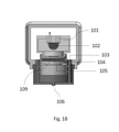
- FIG. 1B illustrates the sectional side view of the atomization device, in accordance with the present invention.
- Fig. 1B illustrates the sectional side view of the atomization device, in accordance with the present invention.
- FIG. 2A illustrates the front view of the atomization device, in accordance with the present invention.
- FIG. 2B illustrates the front view of the blockage indicator, in accordance with one embodiment of the invention.
- FIG. 3 illustrates the cross-sectional view of the blockage indicator, in accordance with one embodiment of the invention.
- FIG. 1 illustrates a flowchart explaining the working of the atomization device, in accordance with the present invention.
- a fluid atomization device comprising of a fluid inlet chamber, an electro-mechanical system present intrinsically in the device, and an orifice for the flow of the fluid.
- the device uses high frequency vibrations to break the molecules of any fluid into smaller droplets in order to reduce the usage of the same.
- fluid atomization device may be extended to atomize any liquid or fluid, and the present disclosure specifically provides the system and method of atomization of water.
- a transducer or an electro-mechanical device may be a piezoelectric transducer, which in the scope of this invention, is utilized in the process of atomization of water.
- an inlet of water to the atomization device can be from any method of storage of water viz. a tank, reservoir, etc. and the outlet can be anything such as, but not limited to, faucets, taps, sprinklers, showers etc.
- the invention talks about an electromechanical device that is utilized for the atomization of water.
- the device called an atomization device as aforementioned, comprises of a fluid inlet chamber, a piezoelectric transducer, a voltage source and an orifice.
- water is led to the device from a storage or similar source where the said water is processed in the device.
- voltage is applied to the transducer from an external source.
- the application of voltage to the device, and consequently to the transducer results in extreme vibrations occurring within the device.
- These extreme vibrations generate ultrasonic waves of a very high frequency. It is apparent to any person skilled in the art that ultrasonic waves, also known as ultrasound, are sound waves that have frequencies beyond the upper limit of normal human hearing.
- Fig. 1 depicts a sectional side-view and front-view of the atomization device 100. It primarily consists of a piezoelectric transducer 105. It also illustrates a fluid (water) inlet chamber 101 present in the device 100 from where the water is introduced to the transducer 105. The fluid inlet chamber 101 receives water from an inlet connected to a storage or a similar source.
- the device 100 consists of a flow restrictor 109 that allows or restricts the flow of the water, according to the requirement of the user.
- the flow restrictor 109 is a disc shaped metallic barrier with an uneven surface that reduces the flow of water entering the surface of the transducer 105.
- the device 100 is powered by an external power source (not shown in the figure).
- a power source can be anything such as, but not limited to, potentiometer, solar energy, supply from an electric board, batteries, generators, etc.
- the application of voltage to the atomization device 100 charges up the transducer 104 which in turn results in extreme vibrations within the device.
- the said vibrations generate an ultrasonic sound of a very high frequency.
- the voltage source may be a potentiometer (not denoted in the Fig) where along with supplying the transducer with right frequency/voltage, the potentiometer also helps in controlling the outlet flow.
- Varying the supply voltage from the potentiometer results in controlling the flow of water from the orifice.
- increasing the voltage supply mayincrease the flow of water from the orifice, and reducing the voltage may reduce the flow of water.
- the orifice 106 converges all the atomized water through itself and sprays it out for the user in a mist form.
- the mist generated through this process is sprayed in a larger radius than normal water and hence is able to cover more surface area.
- the property to cover a larger area in a comparatively lesser amount of water, results in more water being saved than wasted.
- the rate at which the atomized water is discharged from the device depends on the rate at which the liquid is introduced on the atomizing device. Thus, it is likely that the atomization process and the rate at which the water is discharged after the process will also be slow.
- Fig.1 further consists of a micro-system inclusive of two glass-sealed ultraviolet lamps (UV) 102.
- UV glass-sealed ultraviolet lamps
- the said lamps act as a purifier for the flowing water by effectively disinfecting the bacteria like legionella present in the water. It does so by attacking the genetic core of the micro-organisms.
- the atomization device 100 also consists of the charcoal filter 104 for the purposes of water purification.
- the porous surface area of the charcoal and its highly absorbent properties are effective in removing contaminants.
- the charcoal filter 104 act as a backup water purification mechanism in case the ultraviolet lamps 102 fail.
- the mesh filter 107 prevents large sediments of impurities from being let into the atomization device 100.
- An orifice 106 present at the end of the device 100 which acts as a final outlet for the water which discharges water in a mist form.
- Fig. 1 also illustrates a blockage indicator 108 embedded in the device that displays the level of blockage in the charcoal filter 104 explicitly explained further.
- the device may also consist of more than one inlet of water. This may be useful in applications like showers or domestic faucets where mixing of hot and cold water may be required.
- atomization device when the device is used in outlets such as showers, it is possible that more than one atomization device with respective orifices may be arranged in a convergent manner.
- Fig. 2A illustrates a blockage indicator 108 that displays the level of blockage in the charcoal filter 104.
- the blockage indicator 108 alerts the user on water blockage when the flow of water is cut/reduced at charcoal filter 104.
- 104 the flow of water passing travelling through the charcoal filter 104 varies resulting in the change in the electro-mechanical waves emitted by the transducer.
- the abnormal electro-mechanical waves from the transducer are received by a receiver 103 and based on the received signal strength appropriate LED of indicator 108 goes on.
- the indicator may have three LED’s indicating normal flow, caution and the blockage respectively.
- Fig. 2B illustrates an exemplary cross-sectional view of the blockage indicator 108 with respect to the atomization device.
- the fluid atomizer device may have two divisions where first division consists of piezoelectric transducer 105, charcoal filter 104 and flow restrictor 109 and the second division consists of a convergent orifice 106.
- Fig. 3 explains the process 300 of atomization of the water particles in a descriptive illustration.
- the voltage 301 is applied to the transducer 105 present in the device.
- the transducer 105 utilizes this electrical energy and converts it into a mechanical form i.e. the application of voltage to the transducer 105 results in vibrations within the device 302.
- the direction of the vibration is parallel to the flow of the water in the device.
- the water absorbs this vibrational energy partially.
- the absorbed vibrational energy is transformed in the water into standing waves.
- the said waves in the water are automatically arranged in a rectangular grid pattern on the surface with periodic, alternating crests and troughs extending in both directions.
- the water Once the water has been atomized, it is then let through the orifice that is present in the atomization device.
- the orifice further converts the atomized particles into a mist 308 form and discharges them by converging them together.
- Fig. 4 illustrates a flowchart explaining the overall working of the atomization device; wherein voltage is applied to the transducer from an external power source 401 which sets the intrinsic electromechanical device in a vibratory motion 402. The flow of water through these vibrations results in the breaking down of the water particles into smaller droplets 403 i.e. the atomization of water. This atomized water is then discharged through the orifice present in the device in a mist form 404.
- the size of the atomized water particles formed by this method are significantly smaller than the size of the water particles formed by other known methods of atomization.
- the savings achieved by this mechanism see a very significant rise as compared to the rate of usage of the volume of water by the existing methods of atomization.
- Ultramicrons generated by atomizing water have higher penetration properties and utilizing this for showers can help keep skin hydrated, rejuvenated and bright.
- the ultrasonic waves generated in the device not only atomize the water particles, but also help in cleaning the inside of the faucet by self-cleaning the metal on the inside and unblocking smaller blockages, thus reducing the maintenance cost of the device and making the device durable.
- one application of modulating the flow of water by modulating the supply of voltage to the potentiometer is that it can also be used as a self-cleaning mechanism apart from the aforementioned cleaning by ultrasonic waves.
- the maximum rate of flow of water that can be achieved by the tweaking of supply voltage can be utilized in cleaning the inside of the device due to the force of the water.
- Atomized water also finds its applications in heavy industries for cleaning purposes and other applications like acting as a coolant spray for hot surfaces.
- the vegetables and fruits industry can be highly benefitted by this technology as spraying fruits and vegetables with atomized water can help save the amount of water used in the said process and can also help the produce stay fresh for a longer time.
Landscapes
- Special Spraying Apparatus (AREA)
- Physical Or Chemical Processes And Apparatus (AREA)
Abstract
Priority Applications (1)
| Application Number | Priority Date | Filing Date | Title |
|---|---|---|---|
| GB2016511.4A GB2590167B (en) | 2018-03-20 | 2019-01-11 | An electromechanical device for fluid atomization |
Applications Claiming Priority (2)
| Application Number | Priority Date | Filing Date | Title |
|---|---|---|---|
| IN201841010282 | 2018-03-20 | ||
| IN201841010282 | 2018-03-20 |
Publications (1)
| Publication Number | Publication Date |
|---|---|
| WO2019180731A1 true WO2019180731A1 (fr) | 2019-09-26 |
Family
ID=67988376
Family Applications (1)
| Application Number | Title | Priority Date | Filing Date |
|---|---|---|---|
| PCT/IN2019/050024 Ceased WO2019180731A1 (fr) | 2018-03-20 | 2019-01-11 | Dispositif électromécanique pour l'atomisation de fluide |
Country Status (2)
| Country | Link |
|---|---|
| GB (1) | GB2590167B (fr) |
| WO (1) | WO2019180731A1 (fr) |
Citations (4)
| Publication number | Priority date | Publication date | Assignee | Title |
|---|---|---|---|---|
| US4973876A (en) * | 1989-09-20 | 1990-11-27 | Branson Ultrasonics Corporation | Ultrasonic power supply |
| US5230792A (en) * | 1990-01-24 | 1993-07-27 | Christian Sauska | Ultraviolet water purification system with variable intensity control |
| JP2011156481A (ja) * | 2010-02-01 | 2011-08-18 | Mitsubishi Electric Corp | 超音波霧化装置及びそれを備えた設備機器 |
| US20160320349A1 (en) * | 2015-05-01 | 2016-11-03 | Ssi Technologies, Inc. | Method of calibrating a concentration sensor |
Family Cites Families (6)
| Publication number | Priority date | Publication date | Assignee | Title |
|---|---|---|---|---|
| IT1266669B1 (it) * | 1993-11-04 | 1997-01-09 | Teuco Guzzini Srl | Dispositivo di idromassaggio localizzato |
| ITBO20030237A1 (it) * | 2003-04-18 | 2004-10-19 | Teuco Guzzini Spa | Dispositivo per l'idromassaggio localizzato. |
| CN104907215B (zh) * | 2015-07-03 | 2017-12-19 | 厦门建霖工业有限公司 | 带超声波喷雾的出水机构及使用方法 |
| CN106214040A (zh) * | 2016-08-15 | 2016-12-14 | 苏州微木智能系统有限公司 | 一种雾化负离子水洗手装置 |
| CN206763172U (zh) * | 2017-04-21 | 2017-12-19 | 上海森中电器有限公司 | 一种沐浴净水器 |
| CN107694822A (zh) * | 2017-11-13 | 2018-02-16 | 魔水科技(北京)有限公司 | 一种雾化水杀菌方法及杀菌装置 |
-
2019
- 2019-01-11 WO PCT/IN2019/050024 patent/WO2019180731A1/fr not_active Ceased
- 2019-01-11 GB GB2016511.4A patent/GB2590167B/en not_active Expired - Fee Related
Patent Citations (4)
| Publication number | Priority date | Publication date | Assignee | Title |
|---|---|---|---|---|
| US4973876A (en) * | 1989-09-20 | 1990-11-27 | Branson Ultrasonics Corporation | Ultrasonic power supply |
| US5230792A (en) * | 1990-01-24 | 1993-07-27 | Christian Sauska | Ultraviolet water purification system with variable intensity control |
| JP2011156481A (ja) * | 2010-02-01 | 2011-08-18 | Mitsubishi Electric Corp | 超音波霧化装置及びそれを備えた設備機器 |
| US20160320349A1 (en) * | 2015-05-01 | 2016-11-03 | Ssi Technologies, Inc. | Method of calibrating a concentration sensor |
Also Published As
| Publication number | Publication date |
|---|---|
| GB2590167B (en) | 2023-05-17 |
| GB2590167A (en) | 2021-06-23 |
| GB202016511D0 (en) | 2020-12-02 |
Similar Documents
| Publication | Publication Date | Title |
|---|---|---|
| RU2361646C1 (ru) | Пылевая камера с акустическим распылом жидкости | |
| US11364516B2 (en) | Ultrasonic atomizer with acoustic focusing device | |
| JP6080329B2 (ja) | 液剤噴霧装置及び帯電噴霧ヘッド | |
| CN203971652U (zh) | 一种用于降低空气中pm2.5的气雾除霾装置 | |
| WO2013179431A1 (fr) | Dispositif de pulvérisation d'agent liquide, tête d'électrification/pulvérisation et procédé de pulvérisation d'agent liquide | |
| JP2011052900A (ja) | 2流体ノズルを用いた噴霧システム | |
| RU2536064C1 (ru) | Скруббер с движущейся насадкой | |
| US20160228885A1 (en) | Water Outlet Structure for Generating Candle Flame Shaped Water and A Shower Head Mounting the Same | |
| WO2009019984A1 (fr) | Dispositif de revêtement | |
| RU2325217C1 (ru) | Акустическая система газопылеочистки воздушных выбросов | |
| KR20160134255A (ko) | 폐가스 정화시스템 | |
| JP3844384B2 (ja) | 気体処理装置 | |
| CN206356165U (zh) | 一种光触媒专用喷壶 | |
| US11878318B2 (en) | Ultrasonic atomizer with acoustic focusing device | |
| RU2342979C1 (ru) | Скруббер с подвижной насадкой типа импульс 4 | |
| CN206965396U (zh) | 一种水雾除尘系统 | |
| GB2590167A (en) | An electromechanical device for fluid atomization | |
| CN210159391U (zh) | 声波团聚装置结合喷雾的除尘装置 | |
| CN202925325U (zh) | 超声波发生器及超声波洗衣机 | |
| RU2342977C1 (ru) | Акустическая система газопылеочистки воздушных выбросов типа импульс 4 | |
| CN203842453U (zh) | 一种空气净化器以及其中的喷淋器 | |
| RU2656454C1 (ru) | Скруббер с подвижной насадкой | |
| CN112122049A (zh) | 一种大流量高频超细粒径雾化器 | |
| RU2361648C1 (ru) | Конический форсуночный скруббер | |
| RU2568701C1 (ru) | Скруббер с движущейся насадкой |
Legal Events
| Date | Code | Title | Description |
|---|---|---|---|
| 121 | Ep: the epo has been informed by wipo that ep was designated in this application |
Ref document number: 19770660 Country of ref document: EP Kind code of ref document: A1 |
|
| NENP | Non-entry into the national phase |
Ref country code: DE |
|
| ENP | Entry into the national phase |
Ref document number: 202016511 Country of ref document: GB Kind code of ref document: A Free format text: PCT FILING DATE = 20190111 |
|
| WWE | Wipo information: entry into national phase |
Ref document number: 2016511.4 Country of ref document: GB |
|
| 122 | Ep: pct application non-entry in european phase |
Ref document number: 19770660 Country of ref document: EP Kind code of ref document: A1 |
|
| WWG | Wipo information: grant in national office |
Ref document number: 2016511.4 Country of ref document: GB |