WO2019180776A1 - 細胞構造体の製造装置、製造システムおよび製造方法 - Google Patents
細胞構造体の製造装置、製造システムおよび製造方法 Download PDFInfo
- Publication number
- WO2019180776A1 WO2019180776A1 PCT/JP2018/010795 JP2018010795W WO2019180776A1 WO 2019180776 A1 WO2019180776 A1 WO 2019180776A1 JP 2018010795 W JP2018010795 W JP 2018010795W WO 2019180776 A1 WO2019180776 A1 WO 2019180776A1
- Authority
- WO
- WIPO (PCT)
- Prior art keywords
- manufacturing apparatus
- cell
- manufacturing
- needle
- linear members
- Prior art date
- Legal status (The legal status is an assumption and is not a legal conclusion. Google has not performed a legal analysis and makes no representation as to the accuracy of the status listed.)
- Ceased
Links
Images











Classifications
-
- C—CHEMISTRY; METALLURGY
- C12—BIOCHEMISTRY; BEER; SPIRITS; WINE; VINEGAR; MICROBIOLOGY; ENZYMOLOGY; MUTATION OR GENETIC ENGINEERING
- C12M—APPARATUS FOR ENZYMOLOGY OR MICROBIOLOGY; APPARATUS FOR CULTURING MICROORGANISMS FOR PRODUCING BIOMASS, FOR GROWING CELLS OR FOR OBTAINING FERMENTATION OR METABOLIC PRODUCTS, i.e. BIOREACTORS OR FERMENTERS
- C12M25/00—Means for supporting, enclosing or fixing the microorganisms, e.g. immunocoatings
-
- C—CHEMISTRY; METALLURGY
- C12—BIOCHEMISTRY; BEER; SPIRITS; WINE; VINEGAR; MICROBIOLOGY; ENZYMOLOGY; MUTATION OR GENETIC ENGINEERING
- C12M—APPARATUS FOR ENZYMOLOGY OR MICROBIOLOGY; APPARATUS FOR CULTURING MICROORGANISMS FOR PRODUCING BIOMASS, FOR GROWING CELLS OR FOR OBTAINING FERMENTATION OR METABOLIC PRODUCTS, i.e. BIOREACTORS OR FERMENTERS
- C12M21/00—Bioreactors or fermenters specially adapted for specific uses
- C12M21/08—Bioreactors or fermenters specially adapted for specific uses for producing artificial tissue or for ex-vivo cultivation of tissue
-
- C—CHEMISTRY; METALLURGY
- C12—BIOCHEMISTRY; BEER; SPIRITS; WINE; VINEGAR; MICROBIOLOGY; ENZYMOLOGY; MUTATION OR GENETIC ENGINEERING
- C12M—APPARATUS FOR ENZYMOLOGY OR MICROBIOLOGY; APPARATUS FOR CULTURING MICROORGANISMS FOR PRODUCING BIOMASS, FOR GROWING CELLS OR FOR OBTAINING FERMENTATION OR METABOLIC PRODUCTS, i.e. BIOREACTORS OR FERMENTERS
- C12M23/00—Constructional details, e.g. recesses, hinges
- C12M23/40—Manifolds; Distribution pieces
-
- C—CHEMISTRY; METALLURGY
- C12—BIOCHEMISTRY; BEER; SPIRITS; WINE; VINEGAR; MICROBIOLOGY; ENZYMOLOGY; MUTATION OR GENETIC ENGINEERING
- C12M—APPARATUS FOR ENZYMOLOGY OR MICROBIOLOGY; APPARATUS FOR CULTURING MICROORGANISMS FOR PRODUCING BIOMASS, FOR GROWING CELLS OR FOR OBTAINING FERMENTATION OR METABOLIC PRODUCTS, i.e. BIOREACTORS OR FERMENTERS
- C12M25/00—Means for supporting, enclosing or fixing the microorganisms, e.g. immunocoatings
- C12M25/14—Scaffolds; Matrices
-
- C—CHEMISTRY; METALLURGY
- C12—BIOCHEMISTRY; BEER; SPIRITS; WINE; VINEGAR; MICROBIOLOGY; ENZYMOLOGY; MUTATION OR GENETIC ENGINEERING
- C12M—APPARATUS FOR ENZYMOLOGY OR MICROBIOLOGY; APPARATUS FOR CULTURING MICROORGANISMS FOR PRODUCING BIOMASS, FOR GROWING CELLS OR FOR OBTAINING FERMENTATION OR METABOLIC PRODUCTS, i.e. BIOREACTORS OR FERMENTERS
- C12M29/00—Means for introduction, extraction or recirculation of materials, e.g. pumps
- C12M29/02—Percolation
-
- C—CHEMISTRY; METALLURGY
- C12—BIOCHEMISTRY; BEER; SPIRITS; WINE; VINEGAR; MICROBIOLOGY; ENZYMOLOGY; MUTATION OR GENETIC ENGINEERING
- C12M—APPARATUS FOR ENZYMOLOGY OR MICROBIOLOGY; APPARATUS FOR CULTURING MICROORGANISMS FOR PRODUCING BIOMASS, FOR GROWING CELLS OR FOR OBTAINING FERMENTATION OR METABOLIC PRODUCTS, i.e. BIOREACTORS OR FERMENTERS
- C12M33/00—Means for introduction, transport, positioning, extraction, harvesting, peeling or sampling of biological material in or from the apparatus
-
- C—CHEMISTRY; METALLURGY
- C12—BIOCHEMISTRY; BEER; SPIRITS; WINE; VINEGAR; MICROBIOLOGY; ENZYMOLOGY; MUTATION OR GENETIC ENGINEERING
- C12M—APPARATUS FOR ENZYMOLOGY OR MICROBIOLOGY; APPARATUS FOR CULTURING MICROORGANISMS FOR PRODUCING BIOMASS, FOR GROWING CELLS OR FOR OBTAINING FERMENTATION OR METABOLIC PRODUCTS, i.e. BIOREACTORS OR FERMENTERS
- C12M35/00—Means for application of stress for stimulating the growth of microorganisms or the generation of fermentation or metabolic products; Means for electroporation or cell fusion
- C12M35/04—Mechanical means, e.g. sonic waves, stretching forces, pressure or shear stimuli
-
- C—CHEMISTRY; METALLURGY
- C12—BIOCHEMISTRY; BEER; SPIRITS; WINE; VINEGAR; MICROBIOLOGY; ENZYMOLOGY; MUTATION OR GENETIC ENGINEERING
- C12N—MICROORGANISMS OR ENZYMES; COMPOSITIONS THEREOF; PROPAGATING, PRESERVING, OR MAINTAINING MICROORGANISMS; MUTATION OR GENETIC ENGINEERING; CULTURE MEDIA
- C12N5/00—Undifferentiated human, animal or plant cells, e.g. cell lines; Tissues; Cultivation or maintenance thereof; Culture media therefor
- C12N5/06—Animal cells or tissues; Human cells or tissues
- C12N5/0697—Artificial constructs associating cells of different lineages, e.g. tissue equivalents
-
- A—HUMAN NECESSITIES
- A61—MEDICAL OR VETERINARY SCIENCE; HYGIENE
- A61K—PREPARATIONS FOR MEDICAL, DENTAL OR TOILETRY PURPOSES
- A61K35/00—Medicinal preparations containing materials or reaction products thereof with undetermined constitution
- A61K35/12—Materials from mammals; Compositions comprising non-specified tissues or cells; Compositions comprising non-embryonic stem cells; Genetically modified cells
-
- C—CHEMISTRY; METALLURGY
- C12—BIOCHEMISTRY; BEER; SPIRITS; WINE; VINEGAR; MICROBIOLOGY; ENZYMOLOGY; MUTATION OR GENETIC ENGINEERING
- C12N—MICROORGANISMS OR ENZYMES; COMPOSITIONS THEREOF; PROPAGATING, PRESERVING, OR MAINTAINING MICROORGANISMS; MUTATION OR GENETIC ENGINEERING; CULTURE MEDIA
- C12N2513/00—3D culture
Definitions
- the present invention relates to the production of a three-dimensional cell structure or a three-dimensional cell construct using cell aggregates, and in particular, a device method for a three-dimensional cell structure using strip-like and linear members formed in a vertical direction. About.
- the first is the production of artificial tissues and organs intended for human transplantation.
- Artificial tissue is produced in a form that expresses a part of its function, and its final purpose is human transplantation.
- appropriate evaluation and certification are required before transplantation into the human body, and long-term efforts are required.
- the second is a method of utilizing toxicity tests, drug effect determination, pathological determination, embryology, etc. using these three-dimensional cell structures as test pieces.
- a three-dimensional cell structure using only human cells and reproducing the environment in the body or performing the above test in a close environment, an experiment simulating the body can be performed outside the body.
- This enables efficient drug discovery research, personalized medication diagnosis, observational observation of each organ development, and so on.
- it is difficult to predict and evaluate the timing and effect of cancer medication.
- a test piece prepared in a patient's cancer tissue is first evaluated outside the body to evaluate the efficacy of the drug. It is expected to be an indicator for identification.
- Non-Patent Document 1 the phenomenon of cell aggregates (also referred to as “Cluster” in this document) has been known since the 1960s.
- Non-Patent Document 6 shows an idea of handling a three-dimensional cell structure as a “building block”, suggesting that various cells can be used.
- Cell aggregates are roughly circular aggregates composed only of cells.
- Cell aggregates are aggregates composed of cell aggregates and cells and other substances. .
- Patent Document 1 discloses a tissue plug manufacturing method capable of creating a tissue of an arbitrary shape using only cells without using a carrier. Specifically, the cell aggregate is placed in a chamber having a micropore through which only the bottom can pass the culture solution, and the chamber contains a sufficient amount of the culture solution so that a part of the cell aggregate is in contact with the gas phase. Thus, cell aggregates are cultured in an excess amount of the culture solution in the chamber.
- Patent Document 4 discloses a method of producing a three-dimensional cell by laminating a cultured cell flat-cultured on a permeable sheet with the sheet on another flat-cultured cultured cell.
- Japanese Patent No. 412280 U.S. Pat. No. 8,852,932 Japanese Patent No. 4517125 International Application No. PCT / JP2008 / 056826
- International Publication WO2005 / 047496 PLOS ONE Journal. Pone. 0136681, “Scaffold-Free Tubular Tissues Created by a Bio-3D printer Undergo Remolding and Endothelialization when Implanted in Rat Aortae”, Manabu Itoh et al Gordon R, Goel NS, Steinberg MS, Wiseman LL.
- a rheological mechanism sufficient to explain the kinetics of cell sorting. J Theor Biol. 1972; 37: 43-73.
- Patent Document 2 Many of the dispensing methods shown in Patent Document 2 are a method of discharging a mixture of cell mass called bio-ink and a connecting material such as hydrogel or collagen onto a flat surface, or hydrogel or collagen is easily solidified.
- This is a three-dimensional cell structure technique by injecting a cell mass into a scaffold (Scaffold) prepared in advance using a shape-maintaining material, but it has a drawback in that contact between cells is hindered.
- the shape of the three-dimensional cell structure produced by this method depends on the shape retention force of the connecting material, there are restrictions on the size and shape (particularly in the height direction) of the three-dimensional cell structure.
- An object of the present invention is to solve such a conventional problem and to provide a manufacturing apparatus, a manufacturing system, and a manufacturing method for manufacturing a three-dimensional cell structure using a plurality of linear members.
- An apparatus for manufacturing a cell structure is an apparatus for manufacturing a cell structure, and is disposed between at least one upper member, at least one lower member, and the upper member and the lower member.
- a plurality of linear members wherein one end of each linear member is supported by the upper member, and the other end is supported by the lower member;
- the plurality of linear members define a three-dimensional space, and a plurality of cell aggregates can be accommodated in the space.
- the plurality of linear members include a first linear member that generally defines a first surface, and a second that defines a generally second surface that is spaced apart from the first surface.
- the cell aggregate is accommodated in a space formed between the first surface and the second surface.
- the first surface defines an outer shape of the cell structure
- the second surface defines an inner shape of the cell structure.
- the first surface and the second surface are circular.
- the cell aggregate accommodated in the said space is exposed to liquids, such as a culture medium, via the said several linear member.
- the upper member includes a substantially flat member, and the flat member is formed with an insertion hole for introducing the cell aggregate into the space.
- the manufacturing apparatus further includes a slide member in which a plurality of through holes penetrating the plurality of linear members are formed between the upper member and the lower member, and the slide member includes: It is movable between the upper member and the lower member.
- the manufacturing apparatus further includes a plurality of struts communicating the upper member and the lower member, and the slide member is guided by the plurality of struts in a direction approaching or separating from the upper member. It is movable.
- at least one of the plurality of support columns is provided with a regulating member that regulates movement of the slide member.
- the first and second linear members of the claim define the structure of the blood vessel.
- the first and second linear members define a heart valve structure.
- the plurality of linear members are members manufactured by a three-dimensional printer.
- the plurality of linear members are members manufactured by a wire bonding method as used in semiconductor manufacturing.
- the plurality of linear members are members manufactured by molding with a mold.
- a manufacturing system includes a manufacturing apparatus having the above-described configuration, a container that can store the manufacturing apparatus, and that contains a medium that nourishes cell aggregates in the manufacturing apparatus, and a pump that circulates the medium.
- the manufacturing system includes shaking means for shaking the container.
- the manufacturing system optionally includes means for supplying a medium to a specific site.
- a method for producing a cell structure according to the present invention is a method for producing a cell structure using the production apparatus having the above-described configuration, the step of supplying a plurality of cell aggregates to the space, and culturing the cell aggregates And fusing the cell aggregates and detaching the plurality of linear members from the fused cell aggregates.
- a plurality of linear members are detached from the cell aggregate by moving the slide member.
- the step of detaching the plurality of linear members includes the step of individually detaching the linear members.
- a three-dimensional space is formed by a plurality of linear members supported by at least one upper member and at least one lower member, and a plurality of cell aggregates are accommodated in the space. Therefore, a cell aggregate having an arbitrary shape or structure can be easily produced using a plurality of linear members.
- An apparatus for manufacturing a three-dimensional cell construct defines a three-dimensional structure of cell aggregates by a plurality of linear or needle-like members arranged in a vertical direction, and conforms to the three-dimensional structure.
- a three-dimensional cell structure is produced.
- the linear or needle-like member can be processed into an arbitrary shape and can be easily pulled out from the cell structure, such as steel such as stainless steel, plastic, biodegradable material, and other soft materials.
- the plurality of cell aggregates supplied to the production apparatus are cultured in a solution containing a nutrient component and fused to one cell structure.
- the linear or needle-like member can be created in an arbitrary shape using a three-dimensional printer.
- the three-dimensional printer generates a member that defines an arbitrary three-dimensional structure based on the three-dimensional data.
- a linear or needle-shaped member can also be shape
- it can also create using the method of the wire bonder used for the wiring at the time of semiconductor manufacture.
- tubular cell structure is, for example, a blood vessel.
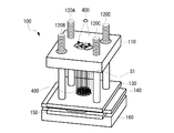
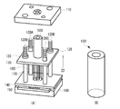
- FIG. 1 is a perspective view showing a cell structure manufacturing apparatus according to an embodiment of the present invention
- FIG. 2 is an exploded perspective view of the cell structure manufacturing apparatus according to an embodiment of the present invention.
- the cell structure manufacturing apparatus 100 of the present embodiment includes a top plate 110, four pins 120A to 120D (hereinafter, collectively referred to as pins 120), a first slide plate 130 having a substantially rectangular shape, A substantially rectangular second slide plate 140, a stopper 150, a base plate 160, an outer needle member 170, and an inner needle member 180 are configured.
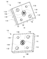
- FIG. 3 is a perspective view of the top plate
- FIG. 3A is a view of the top plate 110 viewed from above
- FIG. 3B is a view of the top plate 110 viewed from below.
- the top plate 110 is composed of a substantially rectangular flat plate member having lengths X1, Y1, and a thickness D1.
- the top plate 110 is formed with substantially circular through holes 112A, 112B, 112C, and 112D (hereinafter sometimes collectively referred to as the through holes 112) in the vicinity of the four corner portions.
- the diameter W1 of the pair of through holes 112A and 112C on the diagonal line is smaller than the diameter W2 of the pair of through holes 112B and 112D on the other diagonal line.
- a pair of substantially elliptical insertion holes 114A and 114B (hereinafter, collectively referred to as the injection holes 114) are formed.
- the introduction hole 114 penetrates the top plate 110, and preferably the introduction hole 114 has a mortar shape in which the diameter on the front surface side is larger than the diameter on the back surface side.
- a medium circulation hole 116 is formed between the pair of charging holes 114A and 114B.
- the culture medium circulation hole 116 is a substantially circular through hole, and is positioned so as to be sandwiched between the charging holes 114.
- the top plate 110 further includes a plurality of needle holes 118A for inserting and supporting the outer peripheral needle-like member 170 as shown in FIG. 9, and a plurality of needles for inserting and supporting the inner peripheral needle-like member 180.
- a hole 118B is formed.
- the needle holes 118A and 118B are through holes arranged substantially concentrically with the medium circulation hole 116.
- FIG. 4 illustrates one pin.
- the pin 120 is an elongated cylindrical member having a length L1 and a diameter W3, and is made of, for example, a steel material.
- the diameter W3 is substantially the same as or slightly smaller than the diameter W1 of the through holes 112A and 112C, and the pin 120 can penetrate the through hole 112.
- Male screw portions 122 and 124 are formed at both ends of the pin 120, and a ring member 126 that meshes with the male screw portion 122 is attached.
- the ring member 126 has an inner diameter W4 substantially equal to the diameter W3 of the pin 120, and its position can be varied by rotating.
- the ring member 126 can move within the range of the axial length L1-1 of the male screw portion 122.
- the ring member 126 may be fixed to the pin 120.
- the outer diameter W5 of the ring member 126 is substantially the same as or slightly smaller than the diameter W2 of the through holes 112B and 112D, and the ring member 126 can penetrate the through holes 112B and 112D. As shown in FIG. 2, the ring member 126 is attached to the pins 120B and 120D and is not attached to the pins 120A and 120C.
- the male screw portion 124 is attached to a base plate 160 described later.
- FIG. 5 shows the first slide plate.
- the first slide plate 130 is a substantially rectangular flat plate-like member having lengths X2, Y2, and a thickness D2.
- the first slide plate 130 has four through-holes 132A, 132B, 132C, and 132D (hereinafter collectively referred to as the through-holes 132) that are aligned with the through-holes 112A, 112B, 112C, and 112D of the top plate 110.
- pins 120A, 120B, 120C, 120D are inserted into these through holes.
- the first slide plate 130 can move in the axial direction of the pin 120 using the pin 120 inserted into the through hole 132 as a guide.
- a plurality of needle holes 134A and 134B in which the outer needle member 170 and the inner needle member 180 can be inserted at positions aligned with the needle holes 118A and 118B ( Hereinafter, they may be collectively referred to as needle holes 134). Furthermore, a medium circulation hole 135 that is a substantially circular through hole is formed inside the needle hole 134B.
- FIG. 6 shows the second slide plate.
- the second slide plate 140 is a substantially rectangular plate-like member having lengths X3 and Y3 and a thickness D3. In one embodiment, X3 ⁇ X2, Y3> Y2 in relation to the first slide plate 130.
- the second slide plate 140 has through holes 142A, 142B, 142C, and 142D (hereinafter collectively referred to as substantially the same size) at positions aligned with the four through holes 132A, 132B, 132C, and 132D of the first slide plate 130. (Sometimes referred to as through-holes 142), and pins 120A, 120B, 120C, and 120D are inserted into these through-holes 142, respectively.
- the outer peripheral needle-like member 170 and the inner peripheral needle-like member 180 are inserted near the center of the second slide plate 140 at positions aligned with the needle holes 118A and 118B.
- a plurality of needle holes 144A and 144B (hereinafter may be collectively referred to as needle holes 144) for support are formed.
- a medium circulation hole 145 that is a substantially circular through hole is formed inside the needle hole 144B.
- Fig. 7 shows the stopper.
- the stopper 150 includes slide guides 156A and 156B (hereinafter sometimes collectively referred to as slide guides 156) that can pass through the grip portion 152, the medium circulation hole 154, and the pin 120.
- the grasping part 152 slightly protrudes between the second slide plate 140 and the base plate 160 as grasped by the manufacturing apparatus 100 shown in FIG. 1, and the stopper 150 is attached to the manufacturing apparatus 100 by pulling the grasping part 152. Can be pulled out from.
- the culture medium circulation hole 154 is a through hole for supplying the culture solution to the cell structure.
- the slide guide 156 is an elongated guide, and one end of the elongated guide is opened.
- the pins 120A and 120B can be passed through the slide guide 156A and the pins 120C and 120D can be passed through the slide guide 156B through the opening.
- the stopper 150 can be inserted and removed between the second slide plate 140 and the base plate 160 even when the manufacturing apparatus 100 as shown in FIG. 1 is assembled. Can do.
- FIG. 7B is a diagram showing the relationship between the stopper 150 and other members.
- the outer peripheral needle-like member 170 and the inner peripheral needle-like member 180 are arranged on the stopper 150.
- the medium circulation hole 154 is disposed so as to enter the inner peripheral needle-like member 180.
- the outer needle member 170 and the inner needle member 180 penetrate the first slide plate 130 and the second slide plate 140 through the needle hole 134 and the needle hole 144. Therefore, the outer needle member 170 and the inner needle member 180 are fixed by the stopper 150 and the second slide plate 140, and the needle member is fixed even if the first slide plate 130 is moved.
- Fig. 8 shows the base plate.
- the base plate 160 is a substantially rectangular member having lengths X4 and Y4 and a thickness D4.
- the base plate 160 is provided with female screw portions 162A, 162B, 162C, and 162D (hereinafter, collectively referred to as female screw portions 162) having substantially the same diameter, and pins 120A, 120B, and 120C, respectively. , 120D.
- the pin 120 is screwed to the base plate 160 by a female screw portion 162 and is held in the vertical direction.
- a through hole 164 having a diameter W6 is provided at the center of the base plate 160, and when the stopper 150 is pulled out, the outer needle member 170 and the inner needle member 180 are pulled out from the through hole 164. be able to.
- FIG. 9 shows a needle-like member.
- the outer needle member 170 has a plurality of needle members 172 arranged in a circular shape, one end of the needle member 172 is bent at a substantially right angle, and the other end penetrates the needle holes 144A, 134A, 118A. it can.
- the inner peripheral needle-like member 180 has a plurality of needle-like members 182 arranged in a circular shape, one end of the needle-like member 182 is bent at a substantially right angle, and the other end passes through the needle holes 144B, 134B, 118B. Can do.
- These needle-like members form a tubular three-dimensional space between the top plate 110 and the first slide plate 130.
- the needle-like member is made of, for example, a stainless material, a plastic material, a biodegradable material, or the like.
- the cross-sectional shape of the needle-like member is arbitrary, but is preferably, for example, a circular shape or an elliptical shape and has a uniform thickness in order to facilitate detachment from the cell aggregate.
- the cross-sectional shape may be triangular or prismatic.
- the surface of the needle-like member may be coated with a non-adhesive material for facilitating detachment from the cell aggregate.
- FIG. 10 is a diagram for explaining a tubular three-dimensional space according to an embodiment of the present invention.
- FIG. 10A shows the outer peripheral needle-like member 170 and the inner peripheral needle-like member 180 of the manufacturing apparatus 100 taken out.
- the inner needle member 180 is inserted into the inner space of the outer needle member 170, and the inner needle member 180 and the outer needle member 170 form a tubular three-dimensional space S1.
- FIG. 10B is an overhead view of FIG. 10A (the bent part of the needle-like member is omitted).
- a tubular cell structure is manufactured by supplying cell aggregates to the three-dimensional space S ⁇ b> 1 by a method for manufacturing a cell structure described later.
- the outer diameter of the tubular cell structure is defined by the diameter W7 of the outer needle member 170, and the inner diameter is defined by the diameter W8 of the inner needle member 180.
- the space S2 becomes a space space of the tubular cell structure.
- a part of the outer needle member 170 is enlarged, and the interval L2 between the needle members is smaller than the supplied cell aggregate. That is, the interval L2 is an interval at which cell aggregates do not leak.
- interval L2 should just be a space
- the space L2 between the needle-like members can pass the culture solution 210 to be described later, a nutrient-containing medium can be supplied from between the needle-like members.
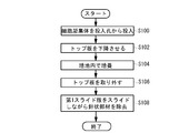
- FIG. 11 is a flowchart showing a method for manufacturing a cell structure according to an embodiment of the present invention.
- a cell aggregate (spheroid) is supplied from the input hole 114 of the manufacturing apparatus 100 (S100).
- FIG. 12 is a diagram illustrating the introduction of cell aggregates according to an example of the present invention.
- the cell aggregate 400 larger than the interval L2 between the needle-like members is introduced from the introduction hole 114, the cell aggregate 400 accumulates in the tubular three-dimensional space S1.
- the top plate 110 is lowered in the Z1 direction so that the cell aggregate 400 adheres to each other and does not move around (S102). .
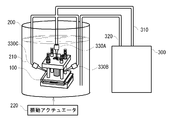
- FIG. 14A is a diagram showing a culture example of cell aggregates.
- the accumulated cell aggregate 400 is put into the container 200 together with the manufacturing apparatus 100.
- the container 200 contains a culture solution 210 in which a nutrient for culturing the cell aggregate 400 is dissolved, and the nutrient is supplied to the cell aggregate 400.
- the circulation pump 300 is prepared, the culture solution is sucked up by the tube 320, and the culture solution 210 is circulated by discharging the culture solution from the tube 310.
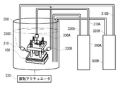
- a nozzle 330 is connected to the tip of the tube 310, and the culture solution can be distributed throughout the cell aggregate by circulating the culture solution through the medium circulation holes 116, 135, and 145. More preferably, a vibration actuator 220 that shakes the container 200 may be prepared, and the container 200 may be cultured while being shaken. Note that when the cell aggregate 400 is cultured, it is preferable to manage the manufacturing system shown in FIG. 14A at a temperature, humidity, light amount, and the like suitable for the culture.
- FIG. 14B is a diagram showing a culture example using a plurality of nozzles.
- a nozzle 330B and a nozzle 330C for supplying a medium from the periphery of the cell aggregate 400 are provided.
- the culture solution sucked up from the tube 320 is again discharged from the three nozzles 330A, 330B, and 330C through the tube 310.
- the circulation pump 300 may have a function of filtering the sucked medium.
- the nozzle 330B and the nozzle 330C may have a fixing mechanism that can be arranged at an arbitrary position, and may efficiently supply a culture solution to an arbitrary part of the cell aggregate 400. Further, the nozzle 330B and the nozzle 330C may be movable to an arbitrary track or position by a driving device or a driving mechanism such as an actuator.
- FIG. 14C is a diagram illustrating an example in which a plurality of nozzles are provided and a culture medium is supplied from another system at the same time.
- the manufacturing system shown in the figure has separate systems of circulation pumps 300A and 300B, and discharge tubes 310A and 310B and suction tubes 320A and 320B are connected to each pump.
- the medium sucked up from the tube 320A is discharged from the nozzle 330A via the tube 310A.
- the culture medium sucked up from the tube 320B is discharged from the nozzles 330B and 330C through the tube 310B.
- the nozzle 330B and the nozzle 330C are connected to a separate tank, only one of the circulation pumps is used. It can also be activated. Further, the nozzle 330B and the nozzle 330C may be movable to an arbitrary track or position by a driving device or a driving mechanism such as an actuator.
- FIG. 15A and FIG. 15B are diagrams for explaining how the produced cell structure is taken out.
- the top plate 110 is removed (S106).
- the cell structure 500 is pulled out from the outer needle member 170 and the inner needle member 180 while sliding the first slide plate 130 in the Z2 direction (S108).
- the stopper 150 can be pulled out in the Z3 direction, and one or more needle-like members can be taken out from the through hole 164 one by one.
- FIG. 15B (A) is a diagram illustrating the manufactured cell structure.
- the outer needle-like member 170 and the inner needle-like member 180 are made of, for example, stainless steel or nylon. It is preferably made of a material such as polyester, and the size is preferably about 10 ⁇ m in diameter. More preferably, a non-adhesive agent such as P-HEMA is coated on the needle-like member and is sterilized with ethanol or the like. More preferably, a non-adhesive is applied in advance to the contact surface between the top plate 110 and the cell structure 500, the contact surface between the first slide plate 130 and the cell structure 500, and the like so that the cell structure 500 can be easily taken out.
- a non-adhesive agent such as P-HEMA
- two sets of the outer peripheral needle-like member 170 and the inner peripheral needle-like member 180 are used so that each defines the outer peripheral surface and the inner peripheral surface of the blood vessel, but this is an example.
- the contour and shape of a cell structure having a more complicated shape can be defined by three or more needle-like members.
- the contour or contour surface defined by the needle-like member is not limited to a spherical surface or a curved surface, and may be a straight one, for example, a contour or shape such as a prismatic cell structure or a polygonal cell structure. Can also be defined.
- the end portions of the outer needle member 170 and the inner needle member 180 are directly inserted into the through holes of the top plate and the second slide plate, thereby supporting these needle members.
- this is an example, and for example, it may be indirectly attached to the top plate and the second slide plate via a dedicated support member or the like.
- the cell structure having a valve portion is, for example, a cell structure imitating a heart valve.
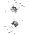
- FIG. 16 is a perspective view showing a cell structure manufacturing apparatus according to another embodiment of the present invention
- FIG. 17 is an exploded perspective view of the cell structure manufacturing apparatus according to the other embodiment. It is.
- the cell structure manufacturing apparatus 100A according to the present example includes an upper frame 610, a lower frame 620, medium circulation holes 630A, 630B, 630C, 630D, and 630E provided in the upper frame 610 and the lower frame 620.
- the medium circulation holes 630 may be collectively referred to), the insertion holes 640A, 640B, 640C (hereinafter, collectively referred to as the injection holes 640) provided in the lower frame 620, the first outer side A needle-shaped member 650, a valve-shaped needle-shaped member upper portion 660, a valve-shaped needle-shaped member middle portion 670, a valve-shaped needle-shaped member lower portion 680, and a second outer needle-shaped member 690 are included.
- the upper frame body 610 and the lower frame body 620 are composed of three pieces as shown in FIGS.
- the upper frame body 610 and the lower frame body 620 are configured by joining the pieces.
- the upper frame body 610 and the lower frame body 620 may each be composed of one member.
- the first outer needle-shaped member 650, the valve-shaped needle-shaped member upper portion 660, and the valve-shaped needle-shaped member middle portion 670 are surfaces of the upper frame 610 (surfaces facing the lower frame 620). ).
- the fixing is performed by forming a plurality of through holes in the upper frame 610 and inserting the needle-like members therein.
- the valve-shaped needle-like member lower part 680 and the second outer needle-like member 690 are fixed to the surface of the lower frame 620 (the surface facing the upper frame 610) in the same manner.
- the cell structure manufacturing apparatus 100A according to the present embodiment can manufacture a heart valve cell structure having a complicated shape by defining the contour of the three-dimensional structure by using such a needle-like member.
- FIG. 18 is a diagram illustrating a cell structure of the heart valve according to the present embodiment.
- the tubular cell structure 700 includes a plurality of valve portions 710 extending inward from the tubular portion (FIG. 18A).
- the valve unit 710 includes three valves 710A, 710B, and 710C.
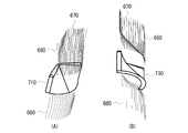
- FIG. 19A is a diagram illustrating molding of a cell structure according to the present example.
- the contour of the valve portion 710 is defined by a space between the convex valve-shaped needle-shaped member lower portion 680 and the valve-shaped needle-shaped member middle portion 670 that spreads in a fan shape.
- FIG. 19B is a schematic cross-sectional view for explaining the molding of the cell structure according to the present example.
- FIG. 19B (A) shows a state where the upper frame 610 and the lower frame 620 of the manufacturing apparatus 100A are separated. By combining the upper frame 610 and the lower frame 620, a manufacturing apparatus 100A as shown in FIG. 16 is obtained. Although not shown here, the positions of the upper frame 610 and the lower frame 620 are adjusted by the pins 120 as shown in FIG.
- FIG. 19B (B) shows a state where the cell aggregate 400 is charged from the charging hole 640.
- the cell aggregate 400 accumulates in the thickness portion of the tube of the cell structure 700 defined by the first outer needle-like member 650 and the second outer needle-like member 690, and when a certain amount is accumulated,
- the valve forming needle-shaped member lower portion 680 and the valve forming needle-shaped member middle portion 670 are accumulated in a space for molding the valve portion 710.
- the space S1 is a space having a medium circulation hole 630E at one end and a medium circulation hole 630D at the other end opposite to the one end, and the culture medium 210 can be circulated.
- the spaces S2 and S3 communicate with the medium circulation hole 630 (A, B, or C), and the culture medium 210 can be supplied to these spaces. Note that since the insertion hole 640 for introducing the cell aggregate 400 is provided in the lower frame 620, the lower frame 620 is shown in the upper part of the drawing in FIG. 19B.
- FIG. 20A is a diagram showing a culture example of cell aggregates according to the present example.
- the manufacturing apparatus 100A is immersed in the culture solution 210 as in the manufacturing system shown in FIG. 14A.
- the culture solution supplied from the circulation pump 300 is discharged from the nozzle 300, and the culture solution can be circulated through the medium circulation holes 630E to 630D.
- FIG. 20B is a diagram illustrating a culture example using a plurality of nozzles according to the present example. In this case, in addition to the nozzle 330A inserted into the medium circulation hole 630E, a nozzle 330B and a nozzle 330C that supply the medium from the periphery of the cell aggregate 400 are used.
- each nozzle can be fixed at an arbitrary position as in the manufacturing system shown in FIG. 14B.
- FIG. 20C is a diagram showing a culture example having a plurality of nozzles according to the present embodiment and supplying a different strain of culture medium simultaneously.
- culture using the circulation pumps 300A and 300B of different systems is possible as in the manufacturing system shown in FIG. 14C.
- the nozzles 330B and 330C shown in FIGS. 20B and 20C are preferably fixed in the vicinity of the medium circulation hole 630 and supply the culture solution 210 to the spaces S2 and S3.
- FIG. 21 is a flowchart showing an example of culturing that has a plurality of nozzles according to the present embodiment and simultaneously supplies another strain of medium.
- the cell aggregate 400 is charged from the charging hole 640 of the manufacturing apparatus 100A (S200).
- the cells are cultured in the medium (S202), and the upper frame body 610 and the lower frame body 620 are removed so as to be separated from the cell structure 700.
Landscapes
- Health & Medical Sciences (AREA)
- Engineering & Computer Science (AREA)
- Life Sciences & Earth Sciences (AREA)
- Wood Science & Technology (AREA)
- Organic Chemistry (AREA)
- Bioinformatics & Cheminformatics (AREA)
- Chemical & Material Sciences (AREA)
- Zoology (AREA)
- Biomedical Technology (AREA)
- Genetics & Genomics (AREA)
- Biotechnology (AREA)
- Biochemistry (AREA)
- General Engineering & Computer Science (AREA)
- General Health & Medical Sciences (AREA)
- Microbiology (AREA)
- Sustainable Development (AREA)
- Molecular Biology (AREA)
- Cell Biology (AREA)
- Immunology (AREA)
- Clinical Laboratory Science (AREA)
- Mechanical Engineering (AREA)
- Apparatus Associated With Microorganisms And Enzymes (AREA)
- Micro-Organisms Or Cultivation Processes Thereof (AREA)
Abstract
複数の線状の部材を用いて3次元構造の細胞構造体を製造する製造装置、製造システムおよび製造方法を提供する。 製造装置100は、トップ板110と、ピン120Aないし120D、第1スライド板130、第2スライド板140、ストッパー150、ベース板160、外周針状部材170、内周針状部材180とを含む。外周針状部材170と内周針状部材180によって規定される管状の3次元空間S1に細胞凝集体400を投入し、蓄積した細胞凝集体400の上部にトップ板110を押し下げる。細胞凝集体400は、培養液210の中に浸されると互いに接着し、3次元空間S1を型とした管状の細胞構造体500が製造される。
Description
本発明は、細胞凝集体を用いた3次元細胞構造体もしくは3次元細胞構築物の製造に関し、特に、垂直方向に形成されたストリップ状、線状の部材を用いた3次元細胞構造体の装置方法に関する。
世界的な人口増加と長寿命化に従い医療行為への要求・要望・需要は高まるばかりであるが、近年は新たな手法として細胞を利用した再生医療が注目されている。個々の細胞をそのまま体内に注入する医療手法はすでに他分野にて実用化されている。この手法の施術は簡易であるが、注入した細胞が所望の部位に定着しにくいという課題がある。
これに対して、大量の細胞を融合させて立体的構造体に作製する手法が開発されてきている。細胞をシャーレ、ゲル状の支持体、針状の支持体などで任意の形状に空間的に保持し、立体構造体を作成する手法である。この手法の用途には大きく二つがあげられる。
一つ目は人体移植目的とした人工組織や人工臓器の作製である。人工組織はその一部分を機能が発現する形で作製されたもので、人体移植が最終目的である。ただし、人体への移植までには相応の評価認定が必要となり、長期的な取り組みが必要である。現状では複雑な形状をした臓器を直接作製することは難しく、単純な形状の臓器(血管など)を作成するにとどまっている。
二つ目は、これらの3次元細胞構造体を用いた毒性検査、薬剤効果判定、病理判定、発生学などを試験片としての活用法である。ヒト細胞のみを用いて3次元細胞構造体を作成し体内の環境を再現もしくは近い環境下にて上記の試験をすることで、体内を模した実験が体外で可能となる。これにより効率的な創薬研究、パーソナライズした投薬診断、各器官発生の観察研究などが可能になる。特にがんの投薬においてはその時期と効果予測判定が難しいが、例えば本技術を利用患者のがん組織にて作成された試験片を体外でまず投薬試験評価判定をすることで、薬効果の見極めの指標となることが期待される。
細胞には、浮遊系細胞と足場依存の接着性細胞の2種類がある。前者には、血液系や免疫系の細胞が属し、後者には臓器や皮膚、骨などの細胞が属する。接着性細胞は、在溶液中で浮いている状態では長期間の生存はできず、ガラスシャーレやハイドロゲルなどの足場に付着することで生存及び増殖させる必要がある。接着性の細胞を非接着の環境下に置くと、細胞は足場を求めて相互に接着し、細胞凝集体が形成され、さらに細胞凝集体同士を何らかの手法で相互に接触した環境下に置くと、それらが接着、融合しさらに大きな3次元細胞構造体を構成する。この現象は広く知られており、非特許文献1~6はこれらの具体的実施例を示すものである。非特許文献1にあるように細胞凝集体(本文献内ではClusterとも表記される)が融合する現象は古く1960年代から知られている。特に非特許文献6にて示されるのは、3次元細胞構造体を「積木ブロック(Building Block)」として扱うアイデアを示しており、多様な細胞が利用可能であることを示唆している。
細胞塊(Spheroid)は、細胞のみで構成されたおおむね円形の凝集体、細胞凝集体凝集体(Cell Aggregate)は、細胞塊及び細胞とそれ以外の物質で構成された凝集体を示すものとする。
特許文献1は、担体を用いることなく細胞だけで任意の形状の組織を作成することができる組織プラグ製造方法を開示する。具体的には、底面のみに培養液が通過できる微細孔を有するチャンバー内に細胞凝集体を入れ、細胞凝集体の一部が気相に接する程度の量の培養液がチャンバー内に含まれるようにして、チャンバー内の培養液よりも過剰量の培養液中で細胞凝集体を培養させるものである。
また、3次元細胞構造体を製造する方法として、特許文献2に示すバイオプリンターのノズルから細胞凝集体を平面上に分注していくディスペンス方式や、特許文献3に示す針状の支持体に細胞塊を貫通させる剣山方式が知られている。さらに特許文献4は、透過性シート上で平面培養した培養細胞を他の平面培養した培養細胞上にシートごと積層し、立体的な細胞を製造する方法を開示している。
特許文献2に示すディスペンス方式の多くは、バイオインクと呼ばれる細胞塊とハイドロゲルやコラーゲンなどの繋ぎ材を混ぜ合わせたものを平面上に吐出していく手法、もしくはハイドロゲルやコラーゲンなどの固まりやすい形状保持可能な材料にてあらかじめ作成した足場(Scaffold)の内部に細胞塊を注入して3次元細胞構造体手法であるが、細胞間の接触が妨げられる欠点がある。また、この手法で作製された3次元細胞構造体の形状は、繋ぎ材の形状保持力に依存するため、3次元細胞構造体の大きさや形状(特に高さ方向)に制限が課される。さらに3次元細胞構造体内に繋ぎ材が残存するので、繋ぎ材が細胞に与える悪影響を排除しきれないという課題が残り、人体移植時、もしくは効果判定時に追加の評価確認が必要となる。また、特許文献3に示す剣山方式は、針状の支持体による形状が制約される。
本発明は、このような従来の課題を解決し、複数の線状の部材を用いて3次元構造の細胞構造体を製造する製造装置、製造システムおよび製造方法を提供することを目的とする。
本発明に係る細胞構造体の製造装置は、細胞構造体の製造装置であって、少なくとも1つの上側部材と、少なくとも1つの下側部材と、前記上側部材と前記下側部材との間に配置され複数の線状の部材であって、各線状の部材の一方の端部が前記上側部材によって支持され、他方の端部が前記下側部材によって支持される、前記複数の線状の部材とを有し、前記複数の線状の部材は3次元空間を規定し、当該空間には複数の細胞凝集体が収容可能である。
ある実施態様では、前記複数の線状の部材は、概ね第1の面を規定する第1の線状の部材と、前記第1の面から離間された概ね第2の面を規定する第2の線状の部材とを含み、第1の面と第2の面との間によって形成された空間内に細胞凝集体を収容する。ある実施態様では、前記第1の面は、前記細胞構造体の外側の形状を規定し、前記第2の面は、前記細胞構造体の内側の形状を規定する。ある実施態様では、前記第1の面および前記第2の面は円形である。ある実施態様では、前記空間内に収容された細胞凝集体は、前記複数の線状の部材を介して培地等の液体に晒される。ある実施態様では、前記上側部材は、概ね平坦な部材を含み、当該平坦な部材には、前記空間内に前記細胞凝集体を投入するための投入孔が形成される。ある実施態様では、製造装置はさらに、前記上側部材と前記下側部材との間に前記複数の線状の部材を貫通する複数の貫通孔が形成されたスライド部材を含み、前記スライド部材は、前記上側部材と前記下側部材との間で移動可能である。ある実施態様では、製造装置はさらに、前記上側部材と前記下側部材を連絡する複数の支柱を含み、前記スライド部材は、前記複数の支柱にガイドされて前記上側部材に接近または離間する方向に移動可能である。ある実施態様では、前記複数の支柱の少なくとも1つには、前記スライド部材の移動を規制する規制部材が設けられる。ある実施態様では、請求項前記第1および第2の線状の部材は、血管の構造を規定する。ある実施態様では、前記第1および第2の線状の部材は、心臓の弁の構造を規定する。ある実施態様では、前記複数の線状の部材は、3次元プリンタにより製造された部材である。ある実施態様では、前記複数の線状の部材は、半導体製造に使われるようなワイヤーボンディング方式により製造された部材である。ある実施態様では、前記複数の線状の部材は、型枠による成型により製造された部材である。
本発明に係る製造システムは、上記構成の製造装置と、前記製造装置を収容可能であり、前記製造装置内の細胞凝集体に栄養を与える培地を収容する容器と、前記培地を循環させるポンプとを有する。ある実施態様では、前記製造システムは、前記容器を震盪させる震盪手段を含む。ある実施態様では、前記製造システムは、任意に特定の部位に培地供給する手段を含む。
本発明に係る細胞構造体の製造方法は、上記構成の製造装置を利用した細胞構造体の製造方法であって、前記空間に複数の細胞凝集体を供給するステップと、前記細胞凝集体を培養し、前記細胞凝集体を融合するステップと、前記融合さされた細胞凝集体から前記複数の線状の部材を離脱させるステップと、を有する。ある実施態様では、前記スライド部材を移動させることにより細胞凝集体から複数の線状の部材を離脱させる。ある実施態様では、前記複数の線状の部材を離脱させるステップは、線状の部材を個別に離脱させるステップを含む。
本発明によれば、少なくとも1つの上側部材と少なくとも1つの下側部材とによって支持された複数の線状の部材により3次元空間を形成し、その空間内に複数の細胞凝集体を収容するようにしたので、複数の線状の部材により任意の形状または構造の細胞凝集体を容易に製造することができる。
本発明の実施の形態に係る3次元細胞構築物の製造装置は、垂直方向に配置された複数の線状または針状の部材により細胞凝集体の3次元構造を規定し、3次元構造に応じた立体形状の細胞構造体を製造する。線状または針状の部材は、任意の形状に加工されることができ、かつ細胞構造体からの引き抜きが容易になるように、ステンレス等の鋼材、プラスチック、生体分解材料、その他の軟質の材料から構成される。ある実施態様では、製造装置に供給された複数の細胞凝集体は、栄養成分を含んだ溶液により培養され、1つの細胞構造体に融合される。また、線状または針状の部材は、3次元プリンタを用いて任意の形状に作成することができる。3次元プリンタは、3次元データに基づき任意の3次元構造を規定する部材を生成する。また、線状または針状の部材は求められる形状を有した型枠を用いて成型することもできる。また、半導体製造時の配線につかわれるワイヤボンダーの手法を用いて作成することもできる。なお、図面のスケールは、本発明を理解するために誇張されており、必ずしも実際の製品等の大きさとは同一ではない点に留意すべきである。
次に、本発明の実施例について図面を参照して説明する。本実施例では、3次元細胞構築物の製造装置を用いて、管状(チューブ状)の細胞構造体を製造する例について説明する。管状の細胞構造体は、例えば、血管である。
図1は、本発明の実施例に係る細胞構造体の製造装置を示す斜視図であり、図2は、本発明の実施例に係る細胞構造体の製造装置の分解斜視図を示す図である。本実施例の細胞構造体の製造装置100は、トップ板110と、4つのピン120Aないし120D(以下、総称してピン120と呼ぶことがある)と、略矩形状の第1スライド板130、略矩形状の第2スライド板140、ストッパー150、ベース板160、外周針状部材170、内周針状部材180とを含んで構成される。
図3は、トップ板の斜視図であり、図3(A)は、トップ板110を上方から見た図、図3(B)は、トップ板110を下方から見た図である。トップ板110は、長さX1、Y1、厚さD1を有する概ね矩形状の平坦な板状部材から構成される。トップ板110には、4つのコーナー部近傍に、概ね円形状の貫通孔112A、112B、112C、112D(以下、総称して貫通孔112と呼ぶことがある)が形成されている。対角線上の一対の貫通孔112A、112Cの径W1は、他方の対角線上の一対の貫通孔112Bおよび112Dの径W2よりも小さい。
トップ板110の中央付近には、略楕円形上の一対の投入孔114A、114B(以下、総称して投入孔114と呼ぶことがある)が形成される。投入孔114は、トップ板110を貫通し、好ましくは、投入孔114は、表面側の径が裏面側の径よりも大きいすり鉢状を有する。一対の投入孔114A、114Bの間には、培地循環穴116が形成される。培地循環穴116は、略円状の貫通孔であり、投入孔114に挟まれるような位置する。トップ板110にはさらに、図9に示すような外周針状部材170を挿入しかつ支持するための複数の針穴118Aと、内周針状部材180を挿入しかつ支持するための複数の針穴118Bとが形成されている。針孔118A、118Bは、培地循環穴116のほぼ同心円上に配置された貫通孔である。
図4に、1つのピンを例示する。ピン120は、長さL1、径W3の細長い円柱状の部材であり、例えば、鋼材から構成される。径W3は、貫通孔112A、112Cの径W1とほぼ同径若しくはそれらよりも若干小さく、ピン120は、貫通孔112を貫通することができる。ピン120の両端には、雄ネジ部122、124が形成され、雄ネジ部122には、これと噛み合うリング部材126が取り付けられる。リング部材126は、ピン120の径W3とほぼ同等の内径W4を有し、回転することによりその位置を可変することができる。リング部材126は、雄ネジ部122の軸方向の長さL1-1の範囲で移動することができる。なお、リング部材126はピン120と固定されていてもよい。
リング部材126の外径W5は、貫通孔112B、112Dの径W2とほぼ同径若しくはそれらよりも若干小さく、リング部材126は、貫通孔112B、112Dを貫通することができる。リング部材126は、図2で示すように、ピン120B、120Dに装着され、ピン120A、ピン120Cには装着されない。雄ネジ部124は、後述するベース板160に取付けられる。
図5に、第1スライド板を示す。第1スライド板130は、長さX2、Y2、厚さD2の略矩形状の平坦な板状部材である。第1スライド板130には、トップ板110の貫通孔112A、112B、112C、112Dと整合する位置に、4つの同じサイズの貫通孔132A、132B、132C、132D(以下、総称して貫通孔132と呼ぶことがある)が形成され、これらの貫通孔内に、ピン120A、120B、120C、120Dが挿入される。第1スライド板130は、貫通孔132内に挿入されたピン120をガイドにして、ピン120の軸方向に移動することができる。また、第1スライド板130の中心付近には、針穴118Aおよび針穴118Bに整合する位置に、外周針状部材170および内周針状部材180を挿入可能な複数の針穴134Aおよび134B(以下、総称して針穴134と呼ぶことがある)が形成される。さらに、針穴134Bの内側には、略円状の貫通孔である培地循環穴135が形成される。
図6に、第2スライド板を示す。第2スライド板140は、長さX3、Y3、厚さD3の略矩形状の板状部材である。ある実施態様では、第1スライド板130との関係において、X3<X2、Y3>Y2である。第2スライド板140には、第1スライド板130の4つの貫通孔132A、132B、132C、132Dと整合する位置に、ほぼ同じサイズの貫通孔142A、142B、142C、142D(以下、総称して貫通孔142と呼ぶことがある)が形成され、これらの貫通孔142内に、それぞれピン120A、120B、120C、120Dが挿入される。また、第2スライド板140の中心付近には、第1スライド板130と同様に、針穴118Aおよび針穴118Bに整合する位置に、外周針状部材170および内周針状部材180を挿入しかつ支持するための複数の針穴144Aおよび144B(以下、総称して針穴144と呼ぶことがある)が形成される。さらに、針穴144Bの内側には、略円状の貫通孔である培地循環穴145が形成される。
図7に、ストッパーを示す。ストッパー150は、図7(A)に示すように、把持部152、培地循環穴154、ピン120を通過可能なスライドガイド156Aおよび156B(以下、総称してスライドガイド156と呼ぶことがある)を含む。把持部152は、図1に示す製造装置100で把握されるように、第2スライド板140とベース板160の間から若干突出しており、把持部152を引っ張ることによって、ストッパー150を製造装置100から引き抜くことができる。培地循環穴154は、培養液を細胞構造体に供給するための貫通孔である。スライドガイド156は、細長状のガイドであり、細長状のガイドの一端が開口している。従って、当該開口を介して、スライドガイド156Aにピン120Aおよび120Bを、スライドガイド156Bにピン120Cおよび120Dを通すことができる。ストッパー150は、このような構造を有することにより、例えば、図1に示すような製造装置100が組み上がっている状態であっても、第2スライド板140とベース板160の間に抜き差しすることができる。
図7(B)は、ストッパー150と他の部材との関係を示す図である。ストッパー150の上には、外周針状部材170および内周針状部材180が配置される。好ましくは、培地循環穴154が内周針状部材180の内側に入るように配置される。外周針状部材170および内周針状部材180は、針穴134および針穴144を介して、第1スライド板130および第2スライド板140を貫通する。従って、ストッパー150と第2スライド板140によって外周針状部材170および内周針状部材180が固定され、第1スライド板130を移動させても、針状部材は固定される。
図8に、ベース板を示す。ベース板160は、長さX4、Y4、厚さD4の略矩形状の部材である。ベース板160には、ほぼ同径の雌ネジ部162A、162B、162C、162D(以下、総称して雌ネジ部162と呼ぶことがある)が設けられており、それぞれ、ピン120A、120B、120C、120Dの雄ネジ部124に対応する。ピン120は、雌ネジ部162によってベース板160にネジ固定され、垂直方向に保持される。また、ベース板160の中心には、径W6の貫通孔164が設けられており、ストッパー150を引き抜いた状態であれば、貫通孔164から外周針状部材170および内周針状部材180を引き抜くことができる。
図9に、針状部材を示す。外周針状部材170は、複数の針状部材172を円形状に配置し、針状部材172の一端は、ほぼ直角に折り曲げられ、他端は、針穴144A、134A、118Aを貫通することができる。内周針状部材180は、複数の針状部材182を円形状に配置し、針状部材182の一端は、ほぼ直角に折り曲げられ、他端は、針穴144B、134B、118Bを貫通することができる。これらの針状部材により、トップ板110と第1スライド板130の間に管状の3次元空間が形成される。針状部材は、例えば、ステンレス材、プラスチック材、生体分解材などから構成される。針状部材の断面形状は任意であるが、細胞凝集体からの離脱を容易にするために例えば円形状もしくは楕円形状であり、かつその太さは一様であることが望ましい。但し、断面形状が三角形状や角柱状であってもよい。また、針状部材の表面は、細胞凝集体からの離脱を容易にするための非接着性のある材質がコーティングされてもよい。
図10は、本発明の実施例に係る管状の3次元空間を説明する図である。図10(A)は、製造装置100の外周針状部材170および内周針状部材180を取り出した図である。内周針状部材180は、外周針状部材170の内部空間に挿入され、内周針状部材180および外周針状部材170によって、管状の3次元空間S1が形成される。図10(B)は、図10(A)の俯瞰図である(針状部材の折り曲げ部は省略されている)。後述する細胞構造体の製造方法により、3次元空間S1に細胞凝集体が供給されることにより、管状の細胞構造体が製造される。従って、管状の細胞構造体の外径は、外周針状部材170の径W7によって規定され、内径は、内周針状部材180の径W8によって規定されることになる。空間S2は、管状の細胞構造体のスペース空間となる。なお、図10(B)では、外周針状部材170の一部を拡大しており、針状部材同士の間隔L2は、供給される細胞凝集体よりも小さい。すなわち、間隔L2は、細胞凝集体が漏れ出ない程度の間隔である。これは、内周針状部材180の針状部材同士の間隔についても同様である。間隔L2は、細胞凝集体が漏れ出ない程度の間隔であれば良く、必ずしもすべての針状部材同士の間隔を一定にする必要はない。なお、針状部材同士の間隔L2は、後述する培養液210を通すことは可能であるため、針状部材の間から栄養の入った培地を供給することができる。
次に、本実施例に係る製造装置100を用いた細胞構造体の製造方法について説明する。図11は、本発明の実施例に係る細胞構造体の製造方法を示すフロー図である。細胞構造体の製造方法は、まず、細胞凝集体(スフェロイド)を製造装置100の投入孔114から供給する(S100)。図12は、本発明の実施例に係る細胞凝集体の投入を説明する図である。針状部材同士の間隔L2よりも大きい細胞凝集体400を投入孔114から投入すると、管状の3次元空間S1に細胞凝集体400が蓄積していく。次に、ある程度、細胞凝集体400を蓄積したところで、図13に示すように、トップ板110をZ1方向に下降させ、細胞凝集体400を互いに密着させ、かつ動き回らないようにする(S102)。
次に、管状に蓄積させた細胞凝集体を培養する(S104)。図14Aは、細胞凝集体の培養例を示す図である。蓄積された細胞凝集体400は、製造装置100ごと容器200に入れられる。容器200には、細胞凝集体400を培養するための養分が溶け込んだ培養液210が入っており、細胞凝集体400に養分を供給する。好ましくは、循環用ポンプ300を用意し、チューブ320で培養液を吸い上げて、チューブ310から培養液を吐き出すことにより培養液210を循環させることができる。チューブ310の先端には、ノズル330が接続されており、培地循環穴116、135、145を介して培養液を循環させることで、細胞凝集体全体に培養液を行き渡らせることができる。さらに好ましくは、容器200を震盪させる振動アクチュエータ220を用意し、容器200を震盪させながら培養するようにしても良い。なお、細胞凝集体400を培養する際は、図14Aに示す製造システムを、培養に適した温度、湿度、光量などで管理することが好ましい。
図14Bは、複数のノズルを用いた培養例を示す図である。この場合、培地循環穴116に挿入されるノズル330Aに加え、細胞凝集体400の周囲から培地を供給するノズル330Bおよびノズル330Cが設けられる。同図に示す製造システムでは、チューブ320から吸い上げられた培養液は、再びチューブ310を介して3つのノズル330A、330B、330Cから排出される。循環用ポンプ300は、吸い上げた培地を濾過する機能を備えるものであってもよい。また、ノズル330Bおよびノズル330Cは、任意の位置に配置可能な固定機構を持ち、細胞凝集体400の任意の部位に効率的に培養液を供給するようにしてもよい。また、ノズル330B及びノズル330Cは、アクチュエーターなどの駆動装置または駆動機構により任意の軌道あるいは位置に移動できるようにしてもよい。
図14Cは、複数のノズルを持ち同時に別系統で培地を供給する例を示す図である。同図に示す製造システムでは、別系統の循環用ポンプ300Aおよび300Bを有し、それぞれのポンプには、吐出用のチューブ310A、310Bと、吸い上げ用のチューブ320A、320Bとが接続されている。チューブ320Aから吸い上げられた培地は、チューブ310Aを介してノズル330Aから吐出される。また、チューブ320Bから吸い上げられた培地は、チューブ310Bを介してノズル330Bおよび330Cから吐出される。この場合、細胞凝集体400の任意の特定の部位に培地を供給することができることに加え、ノズル330Bおよびノズル330Cは別系統のタンクに接続されているため、いずれか一方の循環用ポンプのみを起動させることも可能である。また、ノズル330B及びノズル330Cは、アクチュエーターなどの駆動装置または駆動機構により任意の軌道あるいは位置に移動できるようにしてもよい。
細胞凝集体400は、S104の培養により互いに接着し、3次元空間S1に沿った細胞構造体に成長していく。図15Aおよび図15Bは、製造された細胞構造体を取り出す様子を説明する図である。図15Aに示すように、細胞凝集体400が細胞構造体500に成長すると、まずは、トップ板110が取り外される(S106)。次に、第1スライド板130をZ2方向にスライドさせながら、外周針状部材170および内周針状部材180から細胞構造体500を引き抜いていく(S108)。このとき、針状部材から細胞構造体500が抜きにくい場合には、ストッパー150をZ3方向に引き抜き、貫通孔164から針状部材を1つまたは複数本ずつ取り出すことができる。細胞構造体500が容易に針状部材から引き抜かれる場合には、図15B(A)に示すように、ストッパー150を抜かず、第1スライド板130をスライドさせることで細胞構造体500を抜き取ることができる。図15B(A)のように引き抜けば、外周針状部材170および内周針状部材180が製造装置100に組み込まれた状態で残るため、再度、針状部材を針穴に通す手間を省くことができる。このようにして、第1スライド板130上に管状の細胞構造体500が製造される。図15B(B)は、製造された細胞構造体を例示する図である。
細胞構造体500が製造装置100から取り出される際、細胞構造体500が針状部材と接着してしまうことを防ぐため、外周針状部材170および内周針状部材180は、例えば、ステンレス、ナイロン、ポリエステルなどの材料から構成され、大きさは、直径10μm程度であることが好ましい。さらに好ましくは、P-HEMA等の非接着剤を針状部材にコーティングし、エタノール等によって消毒する。さらに好ましくは、トップ板110と細胞構造体500の接触面、第1スライド板130と細胞構造体500の接触面などに、予め非接着剤を塗布しておき、細胞構造体500を取り出しやすいようにしても良い。
上記実施例では、2組の外周針状部材170と内周針状部材180とを用い、それぞれが血管の外周面と内周面の輪郭を規定するようにしたが、これは一例であり、3組またはそれ以上の針状部材によりさらに複雑な形状を有する細胞構造体の輪郭、形状を規定することができる。さらに針状部材により規定する輪郭または輪郭面は、球面または曲面に限らず、直線的なものであってもよく、例えば、角柱状の細胞構造体、多角形状の細胞構造体などの輪郭または形状を規定することも可能である。
さらに上記実施例では、外周針状部材170および内周針状部材180の端部をトップ板および第2スライド板の貫通孔内に直接挿入することで、これらの針状部材の支持を行ったが、これは一例であり、例えば、専用の支持部材等を介して間接的にトップ板および第2スライド板に取付けるようにしてもよい。
次に、本発明の他の実施例について図面を参照して説明する。他の実施例では、3次元細胞構築物の製造装置を用いて、弁部を有する細胞構造体を製造する例について説明する。弁部を有する細胞構造体は、例えば、心臓弁を模した細胞構造体である。
図16は、本発明の他の実施例に係る細胞構造体の製造装置を示す斜視図であり、図17は、当該他の実施例に係る細胞構造体の製造装置の分解斜視図を示す図である。本実施例に係る細胞構造体の製造装置100Aは、上部枠体610、下部枠体620、上部枠体610および下部枠体620に設けられた培地循環穴630A、630B、630C、630D、630E(以下、総称して培地循環穴630と呼ぶことがある)、下部枠体620に設けられた投入孔640A、640B、640C(以下、総称して投入孔640と呼ぶことがある)、第1外側針状部材650、弁成型針状部材上部660、弁成型針状部材中部670、弁成型針状部材下部680、第2外側針状部材690とを含む。上部枠体610と下部枠体620は、図16や図17に示すように、3つのピースから構成される。これは、上部枠体610や下部枠体620を三次元プリンタ等での製造を容易にするため、それぞれのピースを接合して上部枠体610や下部枠体620が構成される。但し、必ずしも各ピースに分割される必要はなく、上部枠体610および下部枠体620がそれぞれ1つの部材から構成されてもよい。
第1外側針状部材650、弁成型針状部材上部660、弁成型針状部材中部670は、図17(B)に示すように、上部枠体610の面(下部枠体620と対向する面)に固定される。固定は、第1の実施例のときと同様に、上部枠体610に複数の貫通孔を形成し、そこに針状部材が挿入される。弁成型針状部材下部680、第2外側針状部材690は、図17(C)に示すように、下部枠体620の面(上部枠体610と対向する面)に同様の方法で固定される。本実施例に係る細胞構造体の製造装置100Aは、このような針状部材により3次元構造の輪郭を規定し、複雑な形状を有する心臓弁の細胞構造体を製造することができる。
図18は、本実施例に係る心臓弁の細胞構造体の例示する図である。管状の細胞構造体700は、その管状の部分から内側に延在する複数の弁部710を備えている(図18(A))。図18(B)に拡大されるように、弁部710は、3つの弁710A、710B、710Cから構成される。
図19Aは、本実施例に係る細胞構造体の成型を説明する図である。弁部710は、凸型の弁成型針状部材下部680と、扇状に末広がる弁成型針状部材中部670との間の空間によって、その輪郭が規定される。図19Bは、本実施例に係る細胞構造体の成型を説明するための模式的な断面図である。図19B(A)は、製造装置100Aの上部枠体610と下部枠体620とが分離した状態を示している。上部枠体610と下部枠体620を組み合わせることで、図16に示すような製造装置100Aとなる。ここには図示しないが、上部枠体610と下部枠体620は、図1に示すようなピン120によって位置を調整され、かつ間隔を調整される。
図19B(B)は、細胞凝集体400を投入孔640から投入した状態を示している。細胞凝集体400は、第1外側針状部材650、第2外側針状部材690によって規定される細胞構造体700の管の厚さ部分に蓄積していき、ある程度の量が蓄積されると、弁成型針状部材下部680と弁成型針状部材中部670によって規定される弁部710を成型する空間に蓄積される。空間S1は、その一端に培地循環穴630E、当該一端に対向する他端に培地循環穴630Dを有する空間であり、培養液210を循環させることができる。また、空間S2およびS3は、培地循環穴630(AまたはBまたはC)と通じており、これらの空間にも培養液210を供給することができる。なお、細胞凝集体400を投入する投入孔640は、下部枠体620に設けられているため、図19Bでは、下部枠体620が図面上部に記載されている点に留意する。
図20Aは、本実施例に係る細胞凝集体の培養例を示す図である。製造装置100Aは、図14Aで示した製造システムのように培養液210中に浸漬される。ノズル300からは、循環用ポンプ300から供給される培養液が吐出しており、培地循環穴630Eから630Dにかけて培養液を循環させることができる。図20Bは、本実施例に係る複数のノズルを用いた培養例を示す図である。この場合、培地循環穴630Eに挿入されるノズル330Aに加え、細胞凝集体400の周囲から培地を供給するノズル330Bおよびノズル330Cが用いられる。また、図14Bで示した製造システムと同様に、それぞれのノズルを任意の位置に固定することができる。図20Cは、本実施例に係る複数のノズルを持ち同時に別系統の培地を供給する培養例を示す図である。図20に示す製造システムでは、図14Cで示した製造システムと同様に、別系統の循環用ポンプ300Aおよび300Bを用いた培養が可能である。図20Bおよび図20Cで示したノズル330Bおよび330Cは、好ましくは、培地循環穴630の近傍に固定され、空間S2およびS3に培養液210を供給する。
図21は、本実施例に係る複数のノズルを持ち同時に別系統の培地を供給する培養例を示すフローである。まず、製造装置100Aの投入孔640から細胞凝集体400を投入する(S200)。その後、図20Aないし図20Cに示すように培地内で培養し(S202)、上部枠体610および下部枠体620を細胞構造体700から離すように除去する。
以上、本発明の好ましい実施の形態について詳述したが、本発明は、特定の実施形態に限定されるものではなく、特許請求の範囲に記載された本発明の要旨の範囲内において、種々の変形・変更が可能である。
100、100A:製造装置 110:トップ板
112:貫通孔 114:投入孔
116:培地循環穴 118:針穴
120:ピン 122:雄ネジ部
124:雄ネジ部 126:リング部材
130:第1スライド板 132:貫通孔
134:針穴 135:培地循環穴
145:培地循環穴 140:第2スライド板
142:貫通孔 144:針穴
150:ストッパー 152:把持部
154:培地循環穴 156:スライドガイド
160:ベース板 162:雌ネジ部
164:貫通孔 170:外周針状部材
172:針状部材 180:内周針状部材
182:針状部材 200:容器
210:培養液 220:振動アクチュエータ
300:循環用ポンプ 310:チューブ
320:チューブ 330:ノズル
400:細胞凝集体 500:細胞構造体
610:上部枠体 620:下部枠体
630:培地循環穴 640:投入孔
650:第1外側針状部材 660:弁成型針状部材上部
670:弁成型針状部材中部 680:弁成型針状部材下部680
690:第2外側針状部材 700:細胞構造体
710:弁部
112:貫通孔 114:投入孔
116:培地循環穴 118:針穴
120:ピン 122:雄ネジ部
124:雄ネジ部 126:リング部材
130:第1スライド板 132:貫通孔
134:針穴 135:培地循環穴
145:培地循環穴 140:第2スライド板
142:貫通孔 144:針穴
150:ストッパー 152:把持部
154:培地循環穴 156:スライドガイド
160:ベース板 162:雌ネジ部
164:貫通孔 170:外周針状部材
172:針状部材 180:内周針状部材
182:針状部材 200:容器
210:培養液 220:振動アクチュエータ
300:循環用ポンプ 310:チューブ
320:チューブ 330:ノズル
400:細胞凝集体 500:細胞構造体
610:上部枠体 620:下部枠体
630:培地循環穴 640:投入孔
650:第1外側針状部材 660:弁成型針状部材上部
670:弁成型針状部材中部 680:弁成型針状部材下部680
690:第2外側針状部材 700:細胞構造体
710:弁部
Claims (20)
- 細胞構造体の製造装置であって、
少なくとも1つの上側部材と、
少なくとも1つの下側部材と、
前記上側部材と前記下側部材との間に配置され複数の線状の部材であって、各線状の部材の一方の端部が前記上側部材によって支持され、他方の端部が前記下側部材によって支持される、前記複数の線状の部材とを有し、
前記複数の線状の部材は3次元空間を規定し、当該空間には複数の細胞凝集体が収容可能である、製造装置。 - 前記複数の線状の部材は、概ね第1の面を規定する第1の線状の部材と、前記第1の面から離間された概ね第2の面を規定する第2の線状の部材とを含み、第1の面と第2の面との間によって形成された空間内に細胞凝集体を収容する、請求項1に記載の製造装置。
- 前記第1の面は、前記細胞構造体の外側の形状を規定し、前記第2の面は、前記細胞構造体の内側の形状を規定する、請求項2に記載の製造装置。
- 前記第1の面および前記第2の面は球面または曲面である、請求項2または3に記載の製造装置。
- 前記空間内に収容された細胞凝集体は、前記複数の線状の部材を介して培地等の液体に晒される、請求項1ないし4いずれか1つに記載の製造装置。
- 前記上側部材は、概ね平坦な部材を含み、当該平坦な部材には、前記空間内に前記細胞凝集体を投入するための投入孔が形成される、請求項1ないし5いずれか1つに記載の製造装置。
- 製造装置はさらに、前記上側部材と前記下側部材との間に前記複数の線状の部材を貫通する複数の貫通孔が形成されたスライド部材を含み、前記スライド部材は、前記上側部材と前記下側部材との間で移動可能である、請求項1ないし6いずれか1つに記載の製造装置。
- 製造装置はさらに、前記上側部材と前記下側部材を連絡する複数の支柱を含み、前記スライド部材は、前記複数の支柱にガイドされて前記上側部材に接近または離間する方向に移動可能である、請求項1ないし7いずれか1つに記載の製造装置。
- 前記複数の支柱の少なくとも1つには、前記スライド部材の移動を規制する規制部材が設けられる、請求項8に記載の製造装置。
- 前記第1および第2の線状の部材は、血管の構造を規定する、請求項2または3に記載の製造装置。
- 前記第1および第2の線状の部材は、心臓の弁の構造を規定する、請求項2または3に記載の製造装置。
- 前記複数の線状の部材は、3次元プリンタにより製造された部材である、請求項1ないし11いずれか1つに記載の製造装置。
- 前記複数の線状の部材は、半導体製造に使われるようなワイヤーボンディング方式により製造された部材である、請求項1ないし12いずれか1つに記載の製造装置。
- 前記複数の線状の部材は、型枠による成型により製造された部材である、請求項1ないし13いずれか1つに記載の製造装置。
- 請求項1ないし14いずれか1つに記載の製造装置と、前記製造装置を収容可能であり、前記製造装置内の細胞凝集体に栄養を与える培地を収容する容器と、前記培地を循環させるポンプとを有する、細胞構造体を製造するための製造システム。
- 前記製造システムは、前記容器を震盪させる震盪手段を含む、請求項15に記載の製造システム。
- 前記製造システムは、任意に特定の部位に培地を供給する手段を含む、請求項15または16に記載の製造システム。
- 請求項1ないし14いずれか1つに記載の製造装置を利用した細胞構造体の製造方法であって、
前記空間に複数の細胞凝集体を供給するステップと、
前記細胞凝集体を培養し、前記細胞凝集体を融合するステップと、
前記融合さされた細胞凝集体から前記複数の線状の部材を離脱させるステップと、
を有する製造方法。 - 前記スライド部材を移動させることにより細胞凝集体から複数の線状の部材を離脱させる、請求項18に記載の製造方法。
- 前記複数の線状の部材を離脱させるステップは、線状の部材を個別に離脱させるステップを含む、請求項18または19に記載の製造方法。
Priority Applications (5)
| Application Number | Priority Date | Filing Date | Title |
|---|---|---|---|
| JP2018533947A JP6439223B1 (ja) | 2018-03-19 | 2018-03-19 | 細胞構造体の製造装置、製造システムおよび製造方法 |
| EP18911017.4A EP3690020A4 (en) | 2018-03-19 | 2018-03-19 | MANUFACTURING DEVICE, MANUFACTURING SYSTEM, AND MANUFACTURING METHOD FOR CELL STRUCTURE |
| PCT/JP2018/010795 WO2019180776A1 (ja) | 2018-03-19 | 2018-03-19 | 細胞構造体の製造装置、製造システムおよび製造方法 |
| US16/754,086 US20230212490A1 (en) | 2018-03-19 | 2018-03-19 | Production Device, Production System and Production Method for Cell Structure |
| CN201880072190.4A CN111315864A (zh) | 2018-03-19 | 2018-03-19 | 细胞结构体的制造装置、制造系统以及制造方法 |
Applications Claiming Priority (1)
| Application Number | Priority Date | Filing Date | Title |
|---|---|---|---|
| PCT/JP2018/010795 WO2019180776A1 (ja) | 2018-03-19 | 2018-03-19 | 細胞構造体の製造装置、製造システムおよび製造方法 |
Publications (1)
| Publication Number | Publication Date |
|---|---|
| WO2019180776A1 true WO2019180776A1 (ja) | 2019-09-26 |
Family
ID=64668458
Family Applications (1)
| Application Number | Title | Priority Date | Filing Date |
|---|---|---|---|
| PCT/JP2018/010795 Ceased WO2019180776A1 (ja) | 2018-03-19 | 2018-03-19 | 細胞構造体の製造装置、製造システムおよび製造方法 |
Country Status (5)
| Country | Link |
|---|---|
| US (1) | US20230212490A1 (ja) |
| EP (1) | EP3690020A4 (ja) |
| JP (1) | JP6439223B1 (ja) |
| CN (1) | CN111315864A (ja) |
| WO (1) | WO2019180776A1 (ja) |
Families Citing this family (4)
| Publication number | Priority date | Publication date | Assignee | Title |
|---|---|---|---|---|
| EP3940054A4 (en) * | 2019-03-15 | 2022-12-14 | Saga University | CULTURE DEVICE FOR USE IN DRUG DEVELOPMENT STUDIES |
| JP2020198794A (ja) * | 2019-06-07 | 2020-12-17 | ティシューバイネット株式会社 | 培養モールド、振とう培養用容器、培養システム、共培養方法、受精卵及び子宮内膜細胞 |
| JPWO2021111642A1 (ja) * | 2019-12-06 | 2021-06-10 | ||
| CN112143642B (zh) * | 2020-08-28 | 2022-06-14 | 上海交通大学 | 用于体外培养的血管化肿瘤微流控器官芯片及其制备方法 |
Citations (8)
| Publication number | Priority date | Publication date | Assignee | Title |
|---|---|---|---|---|
| US4122280A (en) | 1973-12-20 | 1978-10-24 | Bayer Aktiengesellschaft | Pyrazole derivatives |
| US4517125A (en) | 1983-02-03 | 1985-05-14 | Chugai Seiyaku Kabushiki Kaisha | Novel vitamin D3 derivatives and process for producing the same |
| JP2004321065A (ja) * | 2003-04-24 | 2004-11-18 | Nano Photon Kk | 細胞の培養方法、細胞の培養装置、細胞組織の培養に使用される立体フレームの形成方法、細胞組織の培養に使用される立体フレームの形成装置、及び細胞組織の培養に使用される立体フレーム |
| WO2005047496A1 (ja) | 2003-11-14 | 2005-05-26 | Keio University | 細胞培養法、細胞の三次元培養法、三次元組織、人工臓器、及び組織移植方法 |
| WO2008123614A1 (ja) * | 2007-03-30 | 2008-10-16 | Kyushu University, National University Corporation | 細胞の立体構造体の製造方法 |
| US8852932B2 (en) | 2004-02-24 | 2014-10-07 | The Curators Of The University Of Missouri | Self-assembling cell aggregates and methods of making engineered tissue using the same |
| JP2015213452A (ja) * | 2014-05-08 | 2015-12-03 | 大日本印刷株式会社 | くし形治具付針状治具 |
| WO2018029970A1 (ja) * | 2016-08-10 | 2018-02-15 | Cyberdyne株式会社 | 細胞の立体構造化方法及び立体構造化システム |
Family Cites Families (5)
| Publication number | Priority date | Publication date | Assignee | Title |
|---|---|---|---|---|
| US20070048727A1 (en) * | 2001-04-25 | 2007-03-01 | Michael Shuler | Biliary barrier |
| JP2013510590A (ja) * | 2009-11-17 | 2013-03-28 | ハーバード バイオサイエンス インコーポレーテッド | 臓器を形成および/または分析するためのバイオリアクタ、システムおよび方法 |
| US9457128B2 (en) * | 2012-09-07 | 2016-10-04 | President And Fellows Of Harvard College | Scaffolds comprising nanoelectronic components for cells, tissues, and other applications |
| EP3213776B1 (en) * | 2014-10-31 | 2020-06-17 | FUJIFILM Corporation | Tubular structure, device for producing tubular structure, and method for producing tubular structure |
| JP6882658B2 (ja) * | 2015-10-29 | 2021-06-02 | 澁谷工業株式会社 | 細胞の集合構造体の作製方法および作製装置 |
-
2018
- 2018-03-19 JP JP2018533947A patent/JP6439223B1/ja active Active
- 2018-03-19 EP EP18911017.4A patent/EP3690020A4/en not_active Withdrawn
- 2018-03-19 CN CN201880072190.4A patent/CN111315864A/zh active Pending
- 2018-03-19 WO PCT/JP2018/010795 patent/WO2019180776A1/ja not_active Ceased
- 2018-03-19 US US16/754,086 patent/US20230212490A1/en not_active Abandoned
Patent Citations (8)
| Publication number | Priority date | Publication date | Assignee | Title |
|---|---|---|---|---|
| US4122280A (en) | 1973-12-20 | 1978-10-24 | Bayer Aktiengesellschaft | Pyrazole derivatives |
| US4517125A (en) | 1983-02-03 | 1985-05-14 | Chugai Seiyaku Kabushiki Kaisha | Novel vitamin D3 derivatives and process for producing the same |
| JP2004321065A (ja) * | 2003-04-24 | 2004-11-18 | Nano Photon Kk | 細胞の培養方法、細胞の培養装置、細胞組織の培養に使用される立体フレームの形成方法、細胞組織の培養に使用される立体フレームの形成装置、及び細胞組織の培養に使用される立体フレーム |
| WO2005047496A1 (ja) | 2003-11-14 | 2005-05-26 | Keio University | 細胞培養法、細胞の三次元培養法、三次元組織、人工臓器、及び組織移植方法 |
| US8852932B2 (en) | 2004-02-24 | 2014-10-07 | The Curators Of The University Of Missouri | Self-assembling cell aggregates and methods of making engineered tissue using the same |
| WO2008123614A1 (ja) * | 2007-03-30 | 2008-10-16 | Kyushu University, National University Corporation | 細胞の立体構造体の製造方法 |
| JP2015213452A (ja) * | 2014-05-08 | 2015-12-03 | 大日本印刷株式会社 | くし形治具付針状治具 |
| WO2018029970A1 (ja) * | 2016-08-10 | 2018-02-15 | Cyberdyne株式会社 | 細胞の立体構造化方法及び立体構造化システム |
Non-Patent Citations (8)
| Title |
|---|
| GORDON RGOEL NSSTEINBERG MSWISEMAN LL: "A rheological mechanism sufficient to explain the kinetics of cell sorting", J THEOR BIOL, vol. 37, 1972, pages 43 - 73 |
| JAKAB KDAMON BMARGA FDOAGA OMIRONOV VKOSZTIN IMARKWALD RFORGACS G, RELATING CELL AND TISSUE MECHANICS: IMPLICATIONS AND APPLICATIONS, vol. 237, 2008, pages 2438 - 2449 |
| JAKAB KNEAGU AMIRONOV VMARKWALD RRFORGACS G: "Engineering biological structures of prescribed shape using self-assembling multicellular systems", PROC NATL ACAD SCI USA., vol. 101, 2004, pages 2864 - 2869 |
| MANABU ITOH ET AL.: "Scaffold-Free Tubular Tissues Created by a Bio-3D printer Undergo Remolding and Endothelialization when Implanted in Rat Aortae", PLOS ONE, JOURNAL. PONE. 0136681, 1 September 2015 (2015-09-01) |
| MOLDOVAN NI ET AL.: "Principles of the Kenzan Method for Robotic Cell Spheroid-Based Three-Dimensional Bioprinting", TISSUE ENG. PART B REV., vol. 23, no. 3, 2017, pages 237 - 244, XP055597418, ISSN: 1937-3368, doi:10.1089/ten.teb.2016.0322 * |
| PEREZ-POMARES JMFOTY RA: "Tissue fusion and cell sorting in embryonic development and disease: biomedical implications", BIOESSAYS, vol. 28, 2006, pages 809 - 821 |
| See also references of EP3690020A4 |
| VLADIMIR MIRONOVRICHARD P. VISCONTIVLADIMIR KASYNOCVGABOR FORGACSCHRISTOPHER J. DRAKEROGER R. MARKWALD: "Non Patent Literature 6: Organ printing: Tissue spheroids as building blocks", BIOMATERIALS, vol. 30, no. 12, April 2009 (2009-04-01), pages 2164 - 2174 |
Also Published As
| Publication number | Publication date |
|---|---|
| US20230212490A1 (en) | 2023-07-06 |
| CN111315864A (zh) | 2020-06-19 |
| EP3690020A1 (en) | 2020-08-05 |
| JPWO2019180776A1 (ja) | 2020-04-23 |
| JP6439223B1 (ja) | 2018-12-19 |
| EP3690020A4 (en) | 2020-11-04 |
Similar Documents
| Publication | Publication Date | Title |
|---|---|---|
| JP6256853B1 (ja) | 3次元細胞構造体の製造方法およびそれに用いる支持体 | |
| JP6439223B1 (ja) | 細胞構造体の製造装置、製造システムおよび製造方法 | |
| JP6254127B2 (ja) | マイクロチャネルを有する臓器模倣装置ならびにその使用および製造方法 | |
| JP5583312B2 (ja) | 組織体形成用基材、組織体形成キット、それを用いた組織体形成法、及び該組織体形成法により形成された三次元組織体 | |
| Ingber | From cellular mechanotransduction to biologically inspired engineering: 2009 Pritzker award lecture, BMES annual meeting October 10, 2009 | |
| US10034738B2 (en) | Cardiac tissue constructs and methods of fabrication thereof | |
| TWI390039B (zh) | 細胞培養容器 | |
| US20080038814A1 (en) | Nanotube mat with an array of conduits for biological cells | |
| CN107980057B (zh) | 用于体外3d细胞培养实验的微流控装置 | |
| JP2007515958A (ja) | 培養細胞、細胞培養の方法および機器 | |
| US20240010962A1 (en) | Microfluidic cell culture device and method for cell cultivation | |
| JPH06327462A (ja) | 細胞凝集体の形成方法 | |
| WO2017222065A1 (ja) | 三次元培養皮膚シート、その製造に使用するための細胞培養容器及びその製造方法 | |
| WO2016021498A1 (ja) | 繊維状タンパク質材料の作製方法、および細胞培養方法 | |
| TW202128977A (zh) | 細胞層片製造裝置及細胞層片 | |
| JPWO2007052653A1 (ja) | 培養容器および培養装置 | |
| JP2019076046A (ja) | 心筋細胞を含むシート状組織の張力測定デバイス、システム及びキット | |
| EP4644520A1 (en) | Vertical culture slide device for tissue or cell culture | |
| WO2019012622A1 (ja) | 任意形状の3次元細胞構造体の製造装置およびその製造方法 | |
| US20260103667A1 (en) | In vitro microfluidic spheroid-associated angiogenesis vascularization system and method for making the same | |
| CN116004384A (zh) | 一种可拔插、通量化的多器官互连芯片 | |
| Wilson | Microfluidic Chamber for Isolating Subcellular Components |
Legal Events
| Date | Code | Title | Description |
|---|---|---|---|
| ENP | Entry into the national phase |
Ref document number: 2018533947 Country of ref document: JP Kind code of ref document: A |
|
| 121 | Ep: the epo has been informed by wipo that ep was designated in this application |
Ref document number: 18911017 Country of ref document: EP Kind code of ref document: A1 |
|
| ENP | Entry into the national phase |
Ref document number: 2018911017 Country of ref document: EP Effective date: 20200501 |
|
| NENP | Non-entry into the national phase |
Ref country code: DE |