WO2019180924A1 - Dispositif radar laser - Google Patents
Dispositif radar laser Download PDFInfo
- Publication number
- WO2019180924A1 WO2019180924A1 PCT/JP2018/011771 JP2018011771W WO2019180924A1 WO 2019180924 A1 WO2019180924 A1 WO 2019180924A1 JP 2018011771 W JP2018011771 W JP 2018011771W WO 2019180924 A1 WO2019180924 A1 WO 2019180924A1
- Authority
- WO
- WIPO (PCT)
- Prior art keywords
- light
- light source
- optical
- laser light
- laser
- Prior art date
- Legal status (The legal status is an assumption and is not a legal conclusion. Google has not performed a legal analysis and makes no representation as to the accuracy of the status listed.)
- Ceased
Links
Images






Classifications
-
- G—PHYSICS
- G01—MEASURING; TESTING
- G01S—RADIO DIRECTION-FINDING; RADIO NAVIGATION; DETERMINING DISTANCE OR VELOCITY BY USE OF RADIO WAVES; LOCATING OR PRESENCE-DETECTING BY USE OF THE REFLECTION OR RERADIATION OF RADIO WAVES; ANALOGOUS ARRANGEMENTS USING OTHER WAVES
- G01S7/00—Details of systems according to groups G01S13/00, G01S15/00, G01S17/00
- G01S7/48—Details of systems according to groups G01S13/00, G01S15/00, G01S17/00 of systems according to group G01S17/00
- G01S7/481—Constructional features, e.g. arrangements of optical elements
- G01S7/4811—Constructional features, e.g. arrangements of optical elements common to transmitter and receiver
-
- G—PHYSICS
- G01—MEASURING; TESTING
- G01S—RADIO DIRECTION-FINDING; RADIO NAVIGATION; DETERMINING DISTANCE OR VELOCITY BY USE OF RADIO WAVES; LOCATING OR PRESENCE-DETECTING BY USE OF THE REFLECTION OR RERADIATION OF RADIO WAVES; ANALOGOUS ARRANGEMENTS USING OTHER WAVES
- G01S17/00—Systems using the reflection or reradiation of electromagnetic waves other than radio waves, e.g. lidar systems
- G01S17/02—Systems using the reflection of electromagnetic waves other than radio waves
- G01S17/50—Systems of measurement based on relative movement of target
- G01S17/58—Velocity or trajectory determination systems; Sense-of-movement determination systems
-
- G—PHYSICS
- G01—MEASURING; TESTING
- G01S—RADIO DIRECTION-FINDING; RADIO NAVIGATION; DETERMINING DISTANCE OR VELOCITY BY USE OF RADIO WAVES; LOCATING OR PRESENCE-DETECTING BY USE OF THE REFLECTION OR RERADIATION OF RADIO WAVES; ANALOGOUS ARRANGEMENTS USING OTHER WAVES
- G01S17/00—Systems using the reflection or reradiation of electromagnetic waves other than radio waves, e.g. lidar systems
- G01S17/88—Lidar systems specially adapted for specific applications
- G01S17/95—Lidar systems specially adapted for specific applications for meteorological use
-
- G—PHYSICS
- G01—MEASURING; TESTING
- G01S—RADIO DIRECTION-FINDING; RADIO NAVIGATION; DETERMINING DISTANCE OR VELOCITY BY USE OF RADIO WAVES; LOCATING OR PRESENCE-DETECTING BY USE OF THE REFLECTION OR RERADIATION OF RADIO WAVES; ANALOGOUS ARRANGEMENTS USING OTHER WAVES
- G01S7/00—Details of systems according to groups G01S13/00, G01S15/00, G01S17/00
- G01S7/48—Details of systems according to groups G01S13/00, G01S15/00, G01S17/00 of systems according to group G01S17/00
- G01S7/481—Constructional features, e.g. arrangements of optical elements
-
- G—PHYSICS
- G01—MEASURING; TESTING
- G01S—RADIO DIRECTION-FINDING; RADIO NAVIGATION; DETERMINING DISTANCE OR VELOCITY BY USE OF RADIO WAVES; LOCATING OR PRESENCE-DETECTING BY USE OF THE REFLECTION OR RERADIATION OF RADIO WAVES; ANALOGOUS ARRANGEMENTS USING OTHER WAVES
- G01S7/00—Details of systems according to groups G01S13/00, G01S15/00, G01S17/00
- G01S7/48—Details of systems according to groups G01S13/00, G01S15/00, G01S17/00 of systems according to group G01S17/00
- G01S7/481—Constructional features, e.g. arrangements of optical elements
- G01S7/4814—Constructional features, e.g. arrangements of optical elements of transmitters alone
- G01S7/4815—Constructional features, e.g. arrangements of optical elements of transmitters alone using multiple transmitters
-
- G—PHYSICS
- G01—MEASURING; TESTING
- G01S—RADIO DIRECTION-FINDING; RADIO NAVIGATION; DETERMINING DISTANCE OR VELOCITY BY USE OF RADIO WAVES; LOCATING OR PRESENCE-DETECTING BY USE OF THE REFLECTION OR RERADIATION OF RADIO WAVES; ANALOGOUS ARRANGEMENTS USING OTHER WAVES
- G01S7/00—Details of systems according to groups G01S13/00, G01S15/00, G01S17/00
- G01S7/48—Details of systems according to groups G01S13/00, G01S15/00, G01S17/00 of systems according to group G01S17/00
- G01S7/483—Details of pulse systems
- G01S7/484—Transmitters
-
- G—PHYSICS
- G01—MEASURING; TESTING
- G01S—RADIO DIRECTION-FINDING; RADIO NAVIGATION; DETERMINING DISTANCE OR VELOCITY BY USE OF RADIO WAVES; LOCATING OR PRESENCE-DETECTING BY USE OF THE REFLECTION OR RERADIATION OF RADIO WAVES; ANALOGOUS ARRANGEMENTS USING OTHER WAVES
- G01S7/00—Details of systems according to groups G01S13/00, G01S15/00, G01S17/00
- G01S7/48—Details of systems according to groups G01S13/00, G01S15/00, G01S17/00 of systems according to group G01S17/00
- G01S7/483—Details of pulse systems
- G01S7/486—Receivers
-
- G—PHYSICS
- G01—MEASURING; TESTING
- G01S—RADIO DIRECTION-FINDING; RADIO NAVIGATION; DETERMINING DISTANCE OR VELOCITY BY USE OF RADIO WAVES; LOCATING OR PRESENCE-DETECTING BY USE OF THE REFLECTION OR RERADIATION OF RADIO WAVES; ANALOGOUS ARRANGEMENTS USING OTHER WAVES
- G01S7/00—Details of systems according to groups G01S13/00, G01S15/00, G01S17/00
- G01S7/48—Details of systems according to groups G01S13/00, G01S15/00, G01S17/00 of systems according to group G01S17/00
- G01S7/491—Details of non-pulse systems
- G01S7/4912—Receivers
- G01S7/4917—Receivers superposing optical signals in a photodetector, e.g. optical heterodyne detection
-
- G—PHYSICS
- G01—MEASURING; TESTING
- G01S—RADIO DIRECTION-FINDING; RADIO NAVIGATION; DETERMINING DISTANCE OR VELOCITY BY USE OF RADIO WAVES; LOCATING OR PRESENCE-DETECTING BY USE OF THE REFLECTION OR RERADIATION OF RADIO WAVES; ANALOGOUS ARRANGEMENTS USING OTHER WAVES
- G01S7/00—Details of systems according to groups G01S13/00, G01S15/00, G01S17/00
- G01S7/48—Details of systems according to groups G01S13/00, G01S15/00, G01S17/00 of systems according to group G01S17/00
- G01S7/497—Means for monitoring or calibrating
-
- G—PHYSICS
- G01—MEASURING; TESTING
- G01S—RADIO DIRECTION-FINDING; RADIO NAVIGATION; DETERMINING DISTANCE OR VELOCITY BY USE OF RADIO WAVES; LOCATING OR PRESENCE-DETECTING BY USE OF THE REFLECTION OR RERADIATION OF RADIO WAVES; ANALOGOUS ARRANGEMENTS USING OTHER WAVES
- G01S7/00—Details of systems according to groups G01S13/00, G01S15/00, G01S17/00
- G01S7/48—Details of systems according to groups G01S13/00, G01S15/00, G01S17/00 of systems according to group G01S17/00
- G01S7/481—Constructional features, e.g. arrangements of optical elements
- G01S7/4818—Constructional features, e.g. arrangements of optical elements using optical fibres
-
- Y—GENERAL TAGGING OF NEW TECHNOLOGICAL DEVELOPMENTS; GENERAL TAGGING OF CROSS-SECTIONAL TECHNOLOGIES SPANNING OVER SEVERAL SECTIONS OF THE IPC; TECHNICAL SUBJECTS COVERED BY FORMER USPC CROSS-REFERENCE ART COLLECTIONS [XRACs] AND DIGESTS
- Y02—TECHNOLOGIES OR APPLICATIONS FOR MITIGATION OR ADAPTATION AGAINST CLIMATE CHANGE
- Y02A—TECHNOLOGIES FOR ADAPTATION TO CLIMATE CHANGE
- Y02A90/00—Technologies having an indirect contribution to adaptation to climate change
- Y02A90/10—Information and communication technologies [ICT] supporting adaptation to climate change, e.g. for weather forecasting or climate simulation
Definitions
- the present invention relates to a laser radar device.
- the laser radar device emits oscillation light from the optical antenna into the space, receives the oscillation light reflected or scattered by the object moving in the space with the optical antenna, and based on the result of measuring the Doppler shift of the received oscillation light To measure the moving speed of the object.
- a laser radar device is used in the wind measurement lidar device described in Patent Document 1. This device aims to dynamically change the measurement distance, which is the distance from the optical antenna to the object, so that the oscillation light emitted from the optical antenna is focused at a position separated by the measurement distance. Some lenses included in the antenna are moved to positions corresponding to the measurement distance.
- the conventional laser radar apparatus When controlling the condensing distance of oscillation light by moving some lenses provided in the optical antenna in the optical axis direction, it is necessary to adjust the position of the lens with high accuracy. For example, a resolution of 1 ⁇ m unit is required as a typical positioning resolution of a lens. For this reason, the conventional laser radar apparatus has a drive mechanism that mechanically adjusts the position of the lens, and there is a problem that the size or weight of the optical antenna increases.
- the present invention solves the above-described problems, and a laser radar device capable of dynamically controlling the condensing distance of transmission light without using a drive mechanism that mechanically adjusts the position of a lens provided in an optical antenna.
- the purpose is to obtain.
- the laser radar device includes a plurality of laser light sources, a modulation unit, a plurality of optical antennas, a speed calculation unit, and a control unit.
- the plurality of laser light sources output oscillation light having different wavelengths.
- the modulation unit modulates the frequency and intensity of the oscillation light output from the laser light source.
- the plurality of optical antennas emit the oscillating light modulated by the modulation unit as transmission light that is collected at a position separated by a condensing distance, and the transmission light is reflected by an object existing at a destination of the transmission light. The reflected light is received as received light.
- the speed calculation unit calculates the speed of the object based on the oscillation light output from the laser light source and the reception light received by the optical antenna.
- the control unit controls a plurality of laser light sources.
- the plurality of optical antennas are offset-corrected for the deviation of the condensing point depending on the difference in wavelength of the light input to each, and the oscillation light output from the laser light source is Of these, it is emitted from the optical antenna associated with the laser light source.
- the control unit switches the laser light sources to switch the emission direction of the transmitted light while maintaining the condensing position of the optical antenna, and changes the wavelength of the oscillation light according to the measurement distance to measure the condensing distance Control to fit the distance.
- the laser radar device switches a plurality of laser light sources having different wavelengths of oscillation light to switch the emission direction of the transmission light while maintaining the converging position of the optical antenna, and according to the measurement distance.
- the wavelength of the oscillating light and controlling the condensing distance of the transmitted light to match the measurement distance it is possible to control the oscillation light without using a drive mechanism that mechanically adjusts the position of the lens included in the optical antenna.
- the focusing distance can be dynamically controlled.
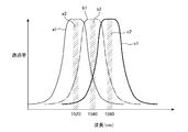
- FIG. 6 is a diagram illustrating transmission characteristics with respect to the wavelength of oscillation light for each input port included in the optical multiplexing unit according to Embodiment 1.
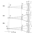
- FIG. 3A is a cross-sectional view showing an optical system of an optical antenna to which oscillation light from a first laser light source is input.
- FIG. 3B is a cross-sectional view showing the optical system of the optical antenna to which the oscillation light from the second laser light source is input.
- FIG. 3C is a cross-sectional view showing an optical system of an optical antenna to which oscillation light from a third laser light source is input.
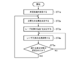
- 3 is a flowchart showing the operation of the laser radar device according to the first embodiment.
- 3 is a flowchart illustrating an operation of a light collection distance control unit in the first embodiment.
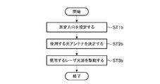
- 3 is a flowchart showing an operation of a direction switching unit in the first embodiment.
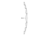
- It is a conceptual diagram which shows the cross section of a diffraction lens.
- It is a block diagram which shows the structure of the laser radar apparatus which concerns on Embodiment 2 of this invention.
- FIG. 12A is a block diagram illustrating a hardware configuration that realizes functions of components that perform signal processing in the laser radar device according to the first or second embodiment.
- FIG. 12B is a block diagram illustrating a hardware configuration that executes software that implements functions of components that perform signal processing in the laser radar device according to Embodiment 1 or Embodiment 2.
- FIG. 1 is a block diagram showing a configuration of a laser radar apparatus 1 according to Embodiment 1 of the present invention, and shows the laser radar apparatus 1 functioning as an anemometer.
- a solid line arrow indicates an optical signal transmission path, for example, an optical fiber.
- a broken arrow indicates an electric signal transmission path.
- the laser radar device 1 measures the wind speed based on the result of measuring the moving speed of the aerosol in the atmosphere. Aerosols are fine liquid or solid particles in the atmosphere.
- the laser radar device 1 changes the wavelength of the oscillation light output from the laser device 2 in accordance with the measurement distance corresponding to the position where the wind speed is desired to be measured so that the converging distance of the oscillation light matches the measurement distance. To do.
- the measurement distance is a distance from the optical antenna device 9 to a position where measurement is desired.
- the condensing distance of the oscillation light is a distance from the optical antenna device 9 to the condensing position of the oscillation light.
- the laser radar apparatus 1 can dynamically control the condensing distance of the oscillation light without using a drive mechanism that mechanically moves the lens included in the optical antenna apparatus 9.
- the laser radar device 1 includes a laser device 2, an optical multiplexing unit 3, an oscillation light branching unit 4, a modulation unit 5, an optical amplifier 6, a circulator 7, an optical antenna device 9, a velocity calculation unit 10, a display unit 11, a control unit 12, and A setting unit 13 is provided.
- the laser device 2 includes a first laser light source 2a, a second laser light source 2b, and a third laser light source 2c.
- the optical antenna device 9 includes a first optical antenna 9a, a second optical antenna 9b, and a third optical antenna 9c.
- the speed calculation unit 10 includes a heterodyne detection unit 10a and a processing unit 10b
- the control unit 12 includes a condensing distance control unit 12a and a direction switching unit 12b.
- the laser device 2 switches and switches the laser light source that outputs oscillation light from the first laser light source 2a, the second laser light source 2b, and the third laser light source 2c.
- the oscillation light output from the laser light source is output to the optical multiplexing unit 3.
- Each of the first laser light source 2a, the second laser light source 2b, and the third laser light source 2c is collectively adjusted to the same temperature by the condensing distance control unit 12a, and the wavelength according to the adjusted temperature.
- the oscillation light is output.
- the oscillation light is continuous wave and constant polarization.
- the condensing distance control unit 12a includes a thermoelectric cooler (hereinafter referred to as TEC), and the TEC performs temperature adjustment.
- TEC thermoelectric cooler
- each of the first laser light source 2a, the second laser light source 2b, and the third laser light source 2c is a laser diode (hereinafter referred to as LD) module.
- the LD module includes, for example, coarse wavelength division multiplexing (hereinafter referred to as CWDM) in which a plurality of distributed feedback laser diodes for wavelength multiplexing optical communication whose wavelength changes linearly with temperature are contained in one package. LD module is used.
- CWDM coarse wavelength division multiplexing
- the wavelength of the oscillation light output from the first laser light source 2a is 1520 nm
- the wavelength of the oscillation light output from the second laser light source 2b is 1540 nm
- the wavelength of the oscillation light output from the third laser light source 2c is It shall be 1560 nm.
- the radar light source to be used is switched by the direction switching unit 12b.
- the oscillation light output from each of the first laser light source 2a, the second laser light source 2b, and the third laser light source 2c is transmitted to the optical multiplexing unit 3 through an optical fiber.
- the first laser light source 2a, the second laser light source 2b, and the third laser light source 2c may be laser light sources that output oscillation light having different wavelengths with respect to the same temperature. It is not limited to the above-mentioned wavelength value.
- the first laser light source 2a, the second laser light source 2b, and the third laser light source 2c are not necessarily integrated LD modules, and may be provided in independent laser devices. That is, the first laser light source 2a, the second laser light source 2b, and the third laser light source 2c may be integrated as long as the temperature can be adjusted by the TEC included in the condensing distance control unit 12a. May be provided.
- the optical multiplexing unit 3 inputs the oscillation light output from the first laser light source 2a, the second laser light source 2b, and the third laser light source 2c through an optical fiber, and combines the input oscillation light.
- the oscillation light combined by the optical multiplexing unit 3 is output to the oscillation light branching unit 4 through the optical fiber.
- the optical multiplexing unit 3 has a function equivalent to, for example, a wavelength division multiplexing (hereinafter referred to as WDM) optical coupler used in an optical communication device, and includes a first input port and a second input port. , A third input port, and an output port.
- the first input port, the second input port, and the third input port transmit light having different wavelength bands.
- the output port transmits light of all wavelengths input to the optical multiplexing unit 3.
- the optical multiplexing unit 3 combines the input three oscillation lights and outputs them from the output port.
- FIG. 2 is a diagram showing transmission characteristics with respect to the wavelength of the oscillation light for each input port included in the optical multiplexing unit 3, where the horizontal axis represents the wavelength of the oscillation light, and the vertical axis represents the transmittance of the oscillation light.
- the transmission characteristic a1 indicates the transmission characteristic for each wavelength of the oscillation light input to the first input port.
- the transmission characteristic b1 indicates the transmittance characteristic for each wavelength of the oscillation light input to the second input port.
- the transmission characteristic c1 indicates the transmission characteristic for each wavelength of the oscillation light input to the third input port.
- the wavelength dependency of the light transmittance is different for each of the first input port, the second input port, and the third input port.
- the oscillation light with a wavelength of 1520 nm from the first laser light source 2a, the oscillation light with a wavelength of 1540 nm from the second laser light source 2b, and the oscillation light with a wavelength of 1560 nm from the third laser light source 2c transmit light of each wavelength. Input to the input port.
- a region a2 indicated by oblique lines is a wavelength variable range of oscillation light output from the first laser light source 2a, and is a region of ⁇ 3 nm centered on a wavelength of 1520 nm.
- a region b2 indicated by oblique lines is a wavelength variable range of oscillation light output from the second laser light source 2b, and is a region of ⁇ 3 nm centered on a wavelength of 1540 nm.
- a region c2 indicated by oblique lines is a wavelength variable range of oscillation light output from the third laser light source 2c, and is a region of ⁇ 3 nm centered on a wavelength of 1560 nm.
- the transmittance of light for each wavelength is almost constant in the region a2, the region b2, and the region c2, and the transmission characteristics. Is flat. For this reason, even if the wavelength of the light input into the input port changes in the region a2, the region b2, and the region c2, the intensity of the light transmitted through the input port is maintained.
- the oscillation light branching unit 4 maintains the polarization of the oscillation light output from the first laser light source 2a, the second laser light source 2b, and the third laser light source 2c while maintaining the polarization of the oscillation light output from the optical multiplexing unit 3.
- the light is branched into transmission light and local oscillation light.
- the transmission light is transmitted to the modulation unit 5 through the optical fiber, and the local oscillation light is transmitted to the heterodyne detection unit 10a through the optical fiber.
- the intensity ratio when the oscillation light output from the optical multiplexing unit 3 is branched into the transmission light and the local oscillation light does not depend on the wavelength of the oscillation light.
- the oscillation light branching unit 4 branches the oscillation light output from the optical multiplexing unit 3 at an equal ratio for all wavelengths.
- the modulation unit 5 outputs the oscillation light (transmission light) output from the first laser light source 2a, the second laser light source 2b, and the third laser light source 2c and input through the optical multiplexing unit 3 and the oscillation light branching unit 4. Modulate frequency and intensity. For example, the modulation unit 5 applies an offset frequency to the transmission light input from the oscillation light branching unit 4 and performs pulse modulation in which the on and off periods are repeated in frequency. When the intensity is modulated by pulse modulation, the oscillation frequency is also modulated. The transmission light modulated by the modulation unit 5 is transmitted to the optical amplifier 6 through the optical fiber.
- the optical amplifier 6 optically amplifies the amplitude of the transmission light input from the modulation unit 5.
- the transmission light optically amplified by the optical amplifier 6 is transmitted to the circulator 7 through the optical fiber.
- the circulator 7 has input / output ports corresponding to three optical fibers between the optical amplifier 6, the optical branching and multiplexing unit 8, and the heterodyne detection unit 10a, and inputs the input light in a predetermined direction. To transmit.
- the circulator 7 outputs the light input from the left input / output port of FIG. 1 only to the right input / output port, and outputs the light input from the right input / output port only to the lower input / output port. To do.
- the circulator 7 outputs the transmission light input from the input / output port connected to the optical fiber between the optical amplifier 6 only to the input / output port connected to the optical fiber between the optical branching and multiplexing unit 8.
- the circulator 7 outputs the received light input from the input / output port connected to the optical fiber between the optical branching and multiplexing unit 8 only to the input / output port connected to the optical fiber between the heterodyne detection unit 10a.
- the optical branching / multiplexing unit 8 has a function equivalent to, for example, a WDM optical coupler used in an optical communication device.
- the optical branching / combining unit 8 branches the transmission light transmitted from the circulator 7 and outputs the branched light to the optical antenna device 9, and combines the three received lights input from the optical antenna device 9 to combine the circulator 7. Output to.
- the optical branching / multiplexing unit 8 has an input / output port connected to the optical fiber between the circulator 7 and an input / output port connected to the optical fiber between the optical antenna device 9.
- the transmission light input from the circulator 7 to the optical branching / multiplexing unit 8 is branched and output to different input / output ports according to the wavelength.
- the transmission light of the wavelength output from the first laser light source 2a is branched and output to the input / output port connected to the first optical antenna 9a by the optical branching / multiplexing unit 8.
- the transmission light having the wavelength output from the second laser light source 2b is branched and output to the input / output port connected to the second optical antenna 9b by the optical branching / multiplexing unit 8.
- the transmitted light having the wavelength output from the third laser light source 2c is branched and output to the input / output port connected to the third optical antenna 9c by the optical branching / multiplexing unit 8.
- the optical branching / multiplexing unit 8 combines the three received lights input from the first optical antenna 9 a, the second optical antenna 9 b, and the third optical antenna 9 c and serves as an input / output port connected to the circulator 7. Output.
- the characteristics of the light transmittance with respect to the wavelength for each input / output port in the optical branching / multiplexing unit 8 are the same as the characteristics of the optical multiplexing unit 3 shown in FIG.
- the transmission characteristic a1 illustrated in FIG. 2 is a transmission characteristic for each wavelength of light input to the input / output port connected to the first optical antenna 9a.
- the transmission characteristic b1 is a transmission characteristic for each wavelength of light input to the input / output port connected to the second optical antenna 9b.
- the transmission characteristic c1 is a transmission characteristic for each wavelength of light input to the input / output port connected to the third optical antenna 9c.
- the input / output port connected to the circulator 7 transmits light regardless of the wavelength. That is, the input / output port connected to the circulator 7 can transmit light of all wavelengths input from the optical antenna device 9.
- the optical multiplexing unit 3 and the optical branching / multiplexing unit 8 may be WDM optical couplers that function equally.
- the optical antenna device 9 emits transmission light that is condensed at a position away from the optical antenna by a condensing distance, and uses reflected light, which is reflected from the object existing at the transmission light emission destination, as reception light. Receive.
- the optical antenna device 9 includes, for example, a first optical antenna 9a, a second optical antenna 9b, and a third optical antenna 9c.
- Each of the first optical antenna 9a, the second optical antenna 9b, and the third optical antenna 9c has a fiber collimator formed of a transmissive lens so as to emit transmission light in different directions. It is configured.
- the reception light received by each of the first optical antenna 9a, the second optical antenna 9b, and the third optical antenna 9c propagates the optical fiber through which the transmission light has been transmitted in the opposite direction to the transmission light.
- the transmitted light having the wavelength output by the laser light source 2c is emitted from the third optical antenna 9c.
- the laser radar device 1 can switch the emission direction of the transmission light by switching the laser light source that outputs the transmission light. For example, when the laser light source that outputs transmission light is switched from the first laser light source 2a to the second laser light source 2b, the optical antenna that emits transmission light is changed from the first optical antenna 9a to the second optical antenna 9b. The direction of emission of the transmitted light is switched. When the laser light source that outputs the transmission light is switched from the second laser light source 2b to the third laser light source 2c, the optical antenna that emits the transmission light is switched from the second optical antenna 9b to the third optical antenna 9c. Instead, the emission direction of the transmitted light is switched.
- FIG. 3A is a cross-sectional view showing the optical system of the optical antenna to which the oscillation light from the first laser light source 2a is inputted, and the position of the output end 90 of the optical fiber, the arrangement of the optical components of the optical antenna, and the oscillation light
- the locus A of the light beam is described.
- FIG. 3B is a cross-sectional view showing the optical system of the optical antenna to which the oscillation light from the second laser light source 2b is inputted.
- the position of the optical fiber emission end 90, the arrangement of optical components of the optical antenna, and the oscillation light Ray trajectories A and B are described.
- 3C is a cross-sectional view showing the optical system of the optical antenna to which the oscillation light from the third laser light source 2c is input, and the position of the output end 90 of the optical fiber, the arrangement of the optical components of the optical antenna, and the oscillation light
- the ray trajectories A and C are described. 3A, 3B, and 3B, the position of the output end 90 of the optical fiber is offset.
- the transmission light emitted from the emission end 90 of the optical fiber is transmitted while being refracted in the order of the lens 91, the lens 92, and the lens 93, thereby having a constant beam diameter and an expansion angle. It is converted into light and emitted into space.
- the lens 91, the lens 92, and the lens 93 have wavelength dispersion of the refractive index of the glass that constitutes them.
- transmission light having different wavelengths is input from the optical fiber, the transmission light is condensed at different condensing distances. It has the characteristic to do.
- the distance between the output end 90 of the optical fiber and the lens 91 is adjusted so that the locus A of the light beam of the transmission light is emitted as parallel light.
- the transmitted light is emitted so as to be condensed, and when the distance between the output end 90 of the optical fiber and the lens 91 is decreased, the transmitted light is diverged. Is released as follows.
- the transmission light emitted from the optical antenna The locus is a divergent locus B.
- the optical antenna inputs the oscillation light output from the second laser light source 2b and the output end 90 of the optical fiber is offset from the position shown in FIG. 3B to the position shown in FIG. 3C (left side position), The light beam of the transmission light changes from a divergent locus B to a parallel light locus C.
- the optical antenna has an offset position of the output end 90 of the optical fiber that makes the transmitted light parallel.
- FIG. 4 is a graph showing the relationship between the wavelength of oscillation light input to the optical antenna device 9 and the offset position of the output end of the optical fiber. As shown in FIG. 4, the same condensing position is maintained with respect to the wavelength of the oscillation light input to the optical antenna device 9, and between the wavelength of the oscillation light and the offset position of the output end of the optical fiber. , There is a relationship of straight line D. The relationship of the straight line D can be calculated in advance from, for example, the wavelength of the oscillation light, the optical system component of the optical antenna device 9, and its position, and the relationship of the calculation results can be tabulated.
- FIG. 5 is a graph showing the relationship between the wavelength of the oscillation light input to the optical antenna device 9 and the focusing distance.
- the laser radar device 1 can be designed so that the wavelength of the oscillation light input to the optical antenna device 9 and the condensing distance of the light of that wavelength are in a relationship of a straight line E. is there. Therefore, by changing the wavelength of the oscillation light output from each of the first laser light source 2a, the second laser light source 2b, and the third laser light source 2c at the same rate of change, the condensing distance can be increased at the same rate. Change.
- the TEC included in the condensing distance control unit 12a adjusts the temperatures of the first laser light source 2a, the second laser light source 2b, and the third laser light source 2c, thereby changing the wavelength of the oscillation light output from them. Change at the same rate of change. Thereby, the condensing distance of the transmission light emitted from each of the first optical antenna 9a, the second optical antenna 9b, and the third optical antenna 9c can be changed at the same rate.
- the laser radar device 1 controls the condensing distance of the transmission light by using the characteristic that the condensing distance of the transmission light emitted from the optical antenna changes when the wavelength of the transmission light input to the optical antenna changes. is doing. As a result, the laser radar device 1 can dynamically control the focusing distance without using a drive mechanism that mechanically adjusts the position of the lens provided in the optical antenna.
- the NA Numerical Aperture
- the transmission light emitted from the optical antenna is 0.1
- the diameter of the beam is assumed to be 60 mm.
- the optical system of the optical antenna is initially adjusted so that the condensing distance of the transmission light is 1900 m.
- the laser radar device 1 changes the condensing distance of the transmission light emitted from the optical antenna from ⁇ to 970 m by changing the wavelength of the oscillation light output from the laser light source within a range of ⁇ 3 nm from the reference wavelength. It becomes possible to change arbitrarily between.
- the optical multiplexing unit 3 and the optical branching / multiplexing unit 8 change the wavelength of oscillation light output from the first laser light source 2a, the second laser light source 2b, and the third laser light source 2c within a range of ⁇ 3 nm. Even so, the light transmittance of the port to which the oscillation light is input is not changed.
- the first laser light source 2a, the second laser light source 2b, and the third laser light source 2c laser light sources having a characteristic that the wavelength of oscillation light changes according to temperature are used.
- the first laser light source 2a, the second laser light source 2b, and the third laser light source 2c are controlled at a constant temperature so that the wavelength of the oscillation light is stabilized at a predetermined value.
- the laser radar device 1 uses the TEC included in the condensing distance control unit 12a, and the temperature of the first laser light source 2a, the second laser light source 2b, and the third laser light source 2c is the wavelength of the oscillation light to be output.
- the temperature is controlled so as to correspond to.
- the speed calculation unit 10 calculates the speed of the object based on the oscillation light (transmission light) output from the laser device 2 and the reception light received by the optical antenna device 9. For example, when the laser radar device 1 functions as an anemometer, the object whose velocity is calculated is an aerosol.
- the velocity calculation unit 10 calculates the velocity of the aerosol at the emission destination of the transmission light using the local oscillation light input from the oscillation light branching unit 4 and the reception light input from the circulator 7, and transmits based on the calculation result. The wind direction and wind speed distribution at the light emission destination is obtained.
- the heterodyne detection unit 10a has a photoelectric conversion unit (not shown), and local oscillation light and reception light are combined and input to this photoelectric conversion unit.
- a photodiode is used for the photoelectric conversion unit.
- the heterodyne detection unit 10a uses the combined signal of the local oscillation light and the reception light converted into the electrical signal by the photoelectric conversion unit, and the light intensity that vibrates at the difference frequency between the local oscillation light and the reception light is converted into the electrical signal.
- the converted beat signal is generated and output to the processing unit 10b.
- the processing unit 10b performs analog-to-digital conversion on the beat signal input from the heterodyne detection unit 10a at a preset sampling rate, and divides the beat signal converted into a digital signal into lengths corresponding to the pulse width of the transmission light. A plurality of beat signal sequences are generated. The plurality of beat signal sequences are stored in a storage area of a memory (not shown) by the processing unit 10b. The process of dividing the beat signal for each pulse width of the transmission light is called “reception gate processing”. Further, the processing unit 10b determines and determines the processing content including the beat signal break length in the reception gate processing based on the information indicating the measurement distance set by the setting unit 13.
- the processing unit 10b performs fast Fourier transform on each of a plurality of beat signal sequences obtained by performing reception gate processing on the beat signal, and calculates a peak value, a spectrum value, and an SN ratio of the power spectrum for each beat signal sequence.
- Each of the plurality of beat signal sequences corresponds to return light (received light) that is affected by the velocity of the object measured at different measurement distances in order of distance from the short distance to the long distance.
- the frequency of the return light is shifted by the Doppler frequency in proportion to the speed of the object.
- the processing unit 10b calculates a Doppler frequency proportional to the wind speed measured at an arbitrary measurement distance using the beat signal sequence, and calculates the wind speed using the calculated Doppler frequency.
- the processing unit 10b stores the measurement distance corresponding to the direction of the transmission light emission destination set by the setting unit 13 and the calculated value of the calculated wind speed in the memory. Since each of the first optical antenna 9a, the second optical antenna 9b, and the third optical antenna 9c is directed in different directions, the processing unit 10b can calculate the wind speed in three directions.
- the processing unit 10b analyzes the wind direction and wind speed distribution in the distance direction by vector calculation using the information stored in the memory. The analysis result of the wind direction and wind speed distribution by the processing unit 10 b is transmitted to the display unit 11.
- the processing unit 10b may set the measurement distance and the measurement direction in the control unit 12.
- the display unit 11 is realized by a display device such as a liquid crystal monitor, and displays the processing result input from the speed calculation unit 10.
- the processing result is an analysis result of the wind direction and wind speed distribution by the speed calculation unit 10.
- the control unit 12 changes the wavelength of the oscillation light output from the laser device 2 according to the measurement distance, controls the condensing distance of the transmission light emitted from the optical antenna device 9, and is emitted from the optical antenna device 9. The direction of emission of transmitted light is controlled.
- the condensing distance control unit 12a changes the wavelength of the oscillation light output from the first laser light source 2a, the second laser light source 2b, and the third laser light source 2c based on the measurement distance set by the setting unit 13. Thus, the condensing distance of the transmission light emitted from the optical antenna device 9 is controlled.
- the condensing distance control unit 12a has a TEC that controls the temperatures of the first laser light source 2a, the second laser light source 2b, and the third laser light source 2c, and changes the temperature to an arbitrary temperature using the TEC. be able to. For example, data in which the relationship between the condensing distance of the transmission light and the wavelength of the transmission light and the relationship between the wavelength of the transmission light and the temperature of the laser light source are tabulated are set in the condensing distance control unit 12a.
- the condensing distance control unit 12 a refers to the data stored in the table, and the transmission distance becomes the measurement distance set by the setting unit 13.
- the temperature of the laser light source corresponding to the wavelength of light is specified.
- the condensing distance control part 12a performs temperature control of the laser light source which made the specified temperature the target using TEC.
- the direction switching unit 12 b switches the directivity direction of the transmission light emitted from the optical antenna device 9 in response to the switching request set by the setting unit 13. For example, the direction switching unit 12b transmits from the first laser light source 2a, the second laser light source 2b, and the third laser light source 2c so that the measurement direction specified in the switching request is the direction of transmission light. A laser light source that emits light is selected and driven.
- the first optical antenna 9a, the second optical antenna 9b, and the third optical antenna 9c are supported and fixed so that the transmitted light emitted is directed in different directions.
- the transmission light output from the first laser light source 2a is emitted from an optical antenna associated in advance among the first optical antenna 9a, the second optical antenna 9b, and the third optical antenna 9c.
- the transmission light output from the second laser light source 2b is the first laser light source 2a and the third laser light source 2c among the first optical antenna 9a, the second optical antenna 9b, and the third optical antenna 9c. Is emitted from an optical antenna other than the optical antenna associated with.
- the transmission light output from the third laser light source 2c is the first laser light source 2a and the second optical antenna among the first optical antenna 9a, the second optical antenna 9b, and the third optical antenna 9c. It is emitted from an optical antenna other than the optical antenna associated with the laser light source 2b. Accordingly, the direction switching unit 12b switches the laser light source that emits the transmission light among the first laser light source 2a, the second laser light source 2b, and the third laser light source 2c, thereby emitting the light from the optical antenna device 9. The direction of the transmitted light is switched.
- the setting unit 13 receives inputs of the measurement distance and the measurement direction, sets the received measurement distance in the light collection distance control unit 12a, and sets the measurement direction in the direction switching unit 12b.
- a wind direction anemometer user inputs a position and direction in which wind speed measurement is desired using an input device (not shown).
- the setting unit 13 specifies a measurement distance that is a distance between the position input using the input device and the position of the optical antenna device 9 and sets information indicating the specified measurement distance in the control unit 12.
- the setting unit 13 specifies a measurement direction that is a direction input using the input device, and sets information indicating the specified measurement direction in the control unit 12.
- the setting unit 13 periodically receives the position and direction from a device outside the laser radar device 1, and sets information indicating the measurement distance and measurement direction specified from the received position and direction in the control unit 12. May be. Information indicating the measurement distance is also set by the setting unit 13 in the processing unit 10b.
- FIG. 6 is a flowchart showing the operation of the laser radar device 1.
- the setting unit 13 sets the measurement distance received from the user in the light collection distance control unit 12a, and sets the measurement direction in the direction switching unit 12b. Furthermore, the setting unit 13 sets the measurement distance in the processing unit 10b. Based on the information indicating the measurement distance set by the setting unit 13, the processing unit 10 b determines and determines the processing content including the length of the beat signal break in the reception gate processing.
- the condensing distance control unit 12a changes the wavelength of the oscillation light output from the laser device 2 in accordance with the measurement distance set by the setting unit 13, so that the condensing distance of the transmission light matches the measurement distance.
- the condensing distance control unit 12a refers to the data in which the relationship between the condensing distance of the transmission light and the wavelength of the transmission light and the relationship between the wavelength of the transmission light and the temperature of the laser light source are tabulated.
- the temperature of the laser light source corresponding to the wavelength of the transmission light whose focusing distance is the measurement distance is specified.
- the condensing distance control part 12a performs temperature control of the laser light source which made the specified temperature the target using TEC. Thereby, the wavelength of the oscillation light output from the laser device 2 changes according to the measurement distance.
- the direction switching unit 12b selects and selects a laser light source to be used from the first laser light source 2a, the second laser light source 2b, and the third laser light source 2c according to the measurement direction set by the setting unit 13.
- the laser light source thus produced is driven (step ST2).
- the direction switching unit 12b includes the first laser light source 2a, the second laser light source 2b, and the third laser light source so that the measurement direction specified by the switching request input from the setting unit 13 is the direction of transmission light.
- a laser light source that emits transmission light is selected from the laser light source 2c and driven.
- the laser light source driven by the control unit 12 outputs continuous wave and constant polarization oscillation light.
- the oscillation light output from the laser light source is transmitted to the oscillation light branching section 4 through the optical multiplexing section 3.
- the oscillation light branching unit 4 branches the oscillation light transmitted from the optical multiplexing unit 3 into transmission light and local oscillation light while maintaining the polarization state.
- the transmission light is transmitted to the modulation unit 5, and the local oscillation light is transmitted to the speed calculation unit 10.
- the modulation unit 5 modulates the frequency and intensity of the transmission light transmitted from the oscillation light branching unit 4.
- the transmission light modulated by the modulation unit 5 is optically amplified by the optical amplifier 6 and transmitted to the optical branching / combining unit 8 by the circulator 7.
- the optical branching / multiplexing unit 8 transmits the transmission light transmitted from the circulator 7 to the optical antenna device 9.
- the optical antenna device 9 emits transmission light from the optical antenna. Since the condensing distance of the transmission light is controlled by the condensing distance control unit 12a so as to match the measurement distance, the transmission light is condensed at the measurement distance.
- the transmission light emitted from the optical antenna device 9 is backscattered by the object in the observation space, and is Doppler frequency shifted according to the moving speed of the object.
- the optical antenna device 9 receives backscattered light, that is, received light that is transmitted light reflected by an object. Since the transmission light is controlled to be condensed at the measurement distance, the intensity of the transmission light is highest at a position away from the optical antenna device 9 by the measurement distance. As a result, even if transmission light is reflected by objects at various positions to become reception light, the ratio of reception light reflected at positions separated by a measurement distance is the largest. For this reason, the SN ratio of the received light reflected at the position separated by the measurement distance is increased.
- the received light received by the optical antenna device 9 is transmitted to the optical branching / multiplexing unit 8, and the optical branching / multiplexing unit 8 is transmitted to the circulator 7.
- the circulator 7 transmits the received light to the speed calculation unit 10.
- the speed calculation unit 10 calculates the speed of the object based on the oscillation light output from the laser light source selected in step ST2 and the received light received by the optical antenna device 9 (step ST3).
- the heterodyne detection unit 10 a performs heterodyne detection using the local oscillation light input from the oscillation light branching unit 4 and the reception light input from the circulator 7. For example, the heterodyne detection unit 10a generates a beat signal having a frequency difference between the local oscillation light and the reception light by optically combining the local oscillation light and the reception light and performing photoelectric conversion.
- the processing unit 10b performs frequency analysis on the beat signal generated by the heterodyne detection unit 10a, and calculates the wind speed in the emission direction of the transmission light at the measurement position. Information indicating the wind speed calculated by the processing unit 10b is stored in a memory included in the laser radar device 1.
- the wind speed measurement using the laser radar device 1 has a wider range of use and is more convenient if it can measure not only the wind speed in one direction but also the three-dimensional wind speed.
- the three-dimensional wind speed can be obtained by a three-point positioning method.
- the direction switching unit 12b sequentially switches the optical antenna that emits the transmission light by switching the laser light source to be used, and the speed calculation unit 10 calculates the wind speed in three different directions near the measurement position.
- the speed calculation unit 10 can estimate the three-dimensional wind speed distribution of the wind speed by vector calculation using the wind speeds in three directions, and can further calculate the wind speed distribution for each measurement distance.
- FIG. 7 is a flowchart showing the operation of the condensing distance control unit 12a, and shows detailed processing in step ST1 of FIG.
- the collection distance control unit 12a matches the collection distance of the transmission light emitted from the optical antenna with the measurement distance set from the setting unit 13.
- the wavelength of the transmission light is determined (step ST2a).
- the condensing distance control unit 12a refers to the data in which the relationship between the condensing distance of the transmission light and the wavelength of the transmission light and the relationship between the wavelength of the transmission light and the temperature of the laser light source are tabulated.
- the wavelength of the transmitted light is determined so that the condensing distance becomes the measurement distance.
- the condensing distance control unit 12a determines the temperature T at which the laser light source outputs the transmission light having the determined wavelength (step ST3a). For example, the condensing distance control unit 12a determines the temperature T at which the laser light source outputs the light having the wavelength determined in step ST2a by referring to the table data.
- the condensing distance control unit 12a uses the TEC so that the temperatures of the first laser light source 2a, the second laser light source 2b, and the third laser light source 2c are the temperatures T determined in step ST3a. Adjust (step ST4a). Of the first laser light source 2a, the second laser light source 2b, and the third laser light source 2c adjusted to the temperature T, the laser light source corresponding to the optical antenna that emits the transmission light is determined in step ST2a. Outputs oscillation light of wavelength. Thereby, the condensing distance of the transmission light emitted from the optical antenna is controlled so as to coincide with the measurement distance set by the setting unit 13.
- the condensing distance control unit 12a determines whether or not a new measurement distance is set from the setting unit 13 (step ST5a). Here, if a new measurement distance is not set (step ST5a; NO), the condensing distance control unit 12a returns to the process of step ST4a, and the first laser light source 2a, the second laser light source 2b, and the third The temperatures of the laser light sources 2c are maintained at the temperature T in a lump.
- step ST5a When a new measurement distance is set from the setting unit 13 (step ST5a; YES), the light collection distance control unit 12a returns to the process of step ST2a, and sets the newly set measurement distance and the transmission light collection distance.
- the above-described series of processing is repeated so that.
- the temperatures of the first laser light source 2a, the second laser light source 2b, and the third laser light source 2c are collectively controlled.
- the wavelength is controlled to match the distance.
- FIG. 8 is a flowchart showing the operation of the direction switching unit 12b, and shows detailed processing in step ST2 of FIG.
- the direction switching unit 12b determines an optical antenna whose transmission light emission direction matches the measurement direction set from the setting unit 13 (step ST2b).
- each of the first optical antenna 9a, the second optical antenna 9b, and the third optical antenna 9c emits transmission light in different directions.
- the setting unit 13 selects a measurement direction from three directions in which these optical antennas emit transmission light, and sets the selected measurement direction in the direction switching unit 12b.
- the measurement direction may be selected by the user using the input device.
- the direction switching unit 12b selects and drives a laser light source corresponding to the optical antenna determined in step ST2b among the first laser light source 2a, the second laser light source 2b, and the third laser light source 2c (step ST3b). ). For example, when the laser light source associated with the optical antenna determined in step ST2b among the first laser light source 2a, the second laser light source 2b, and the third laser light source 2c is the third laser light source 2c, The direction switching unit 12b selects this laser light source.
- the laser radar device 1 determines the optical antenna to be used based on the directivity direction of the transmission light emitted from the optical antenna and the measurement direction set by the setting unit 13, and the laser associated with the determined optical antenna By driving the light source, the emission direction of the transmission light can be switched.
- the emission ends of the optical fibers in the first optical antenna 9a, the second optical antenna 9b, and the third optical antenna 9c are the first laser light source 2a, the second laser light source 2b, and the third laser light source.
- the transmission light is arranged at an offset position where the transmission light is collected at an equal distance.
- measurement can be performed under the same condensing distance and with the same light transmittance of the optical multiplexing unit 3 and the optical branching / multiplexing unit 8.
- measurement equivalent to a configuration in which optical path scanning is mechanically performed can be realized without using a mechanical scanning mechanism.
- a diffractive lens having wavelength dispersion characteristics may be used for the optical system provided in the first optical antenna 9a, the second optical antenna 9b, and the third optical antenna 9c.
- a diffractive lens having wavelength dispersion characteristics may be used for the optical system provided in the first optical antenna 9a, the second optical antenna 9b, and the third optical antenna 9c.
- FIG. 9 is a conceptual diagram showing a cross section of the diffractive lens 91A.
- the diffractive lens 91A is used in place of the lens 91 provided in the optical system of the optical antenna shown in FIGS. 3A, 3B, and 3C.
- a curve indicated by a broken line in FIG. 9 is the surface of the lens 91 described for comparison with the surface of the diffractive lens 91A.
- the surface of the diffractive lens 91A has a shape having a plurality of steps as shown in FIG. 9 in order to diffract incident light. As for these level
- a lens effect is produced by configuring the diffractive lens 91A so that the stepped surface is an integral multiple of the wavelength of the incident light.
- the diffractive lens 91A Since the diffractive lens 91A produces a lens effect due to the minute structure of the wavelength order of incident light, the optical system of the optical antenna can be reduced in size.
- the diffractive lens 91A has a large wavelength dispersion characteristic, and the condensing distance of the emitted light changes according to the wavelength of the incident light.
- the wavelength dispersion characteristic of the condensing distance can be increased. Therefore, in the diffractive lens 91A, as compared with the lens 91, the condensing distance of the outgoing light is changed with respect to the change in wavelength of the incident light. The variable range becomes large.
- the diffractive lens 91A is not limited to the shape shown in FIG.
- An independent diffractive lens may be used or a plurality of diffractive lenses may be used as long as the variable distance of the condensed distance of the outgoing light can be increased with respect to the wavelength of the incident light.
- the laser radar device 1 has been described as having three pairs of laser light sources and optical antennas. However, four or more pairs may be provided, or two pairs may be provided.
- at least three pairs of laser light sources and optical antennas are required.
- one pair or two pairs can be measured.
- the optical antenna does not require a driving mechanism for mechanically moving the lens, and an increase in the weight and size of the optical antenna can be suppressed.
- the TEC included in the first laser light source 2a, the second laser light source 2b, the third laser light source 2c, and the focusing distance control unit 12a may be realized by a laser module in which these are integrated.
- the laser radar device 1 switches the emission direction of the transmission light while maintaining the condensing position of the optical antenna by switching a plurality of laser light sources having different wavelengths of oscillation light.
- the wavelength of the oscillation light is changed according to the measurement distance, and control is performed so that the collection distance of the transmission light matches the measurement distance.
- the laser radar apparatus 1 can dynamically control the condensing distance of the oscillation light without using a drive mechanism that mechanically adjusts the position of the lens included in the optical antenna.
- the drive mechanism which moves a lens mechanically is unnecessary, it is possible to suppress the increase in the weight and dimension of the optical antenna device 9.
- the laser radar apparatus 1 includes a setting unit 13 that receives a measurement distance and sets the received measurement distance in the control unit 12.
- the control unit 12 performs control so that the condensing distance of the transmission light matches the measurement distance set from the setting unit 13. With this configuration, the user uses the setting unit 13 to set the measurement distance in the control unit 12.
- each of the first laser light source 2a, the second laser light source 2b, and the third laser light source 2c outputs oscillation light having a wavelength according to temperature.
- the control unit 12 adjusts the temperatures of the first laser light source 2a, the second laser light source 2b, and the third laser light source 2c to change the wavelength of the oscillation light.
- the control unit collectively adjusts each of the first laser light source 2a, the second laser light source 2b, and the third laser light source 2c to the same temperature, whereby the first laser light source 2a, the second laser light source 2b, The laser light source 2b and the third laser light source 2c output oscillation light having a wavelength corresponding to the adjusted temperature.
- the laser radar apparatus 1 can adjust the condensing distance of three transmission lights simultaneously.
- the first optical antenna 9a, the second optical antenna 9b, and the third optical antenna 9c include a diffractive lens 91A.
- the oscillation light outputted from each of the first laser light source 2a, the second laser light source 2b, and the third laser light source 2c is emitted through the diffraction lens 91A.
- the variable width of the condensing distance of the transmission light emitted from the optical antenna device 9 can be increased.
- FIG. FIG. 10 is a block diagram showing a configuration of a laser radar apparatus 1A according to Embodiment 2 of the present invention, and shows the laser radar apparatus 1A functioning as an anemometer.
- a solid line arrow indicates an optical signal transmission path, for example, an optical fiber.
- a broken arrow indicates an electric signal transmission path.
- the laser radar apparatus 1A changes the wavelength of the oscillation light output from the laser apparatus 2 in accordance with the measurement distance corresponding to the position where the wind velocity is desired to be measured, so that the condensing distance of the oscillation light matches the measurement distance. To do.
- the laser radar device 1A includes a laser device 2, an optical multiplexing unit 3, an oscillation light branching unit 4, a modulation unit 5, an optical amplifier 6, a circulator 7, an optical antenna device 9A, a speed calculation unit 10, a display unit 11, a control unit 12A, and A setting unit 13 is provided.
- the laser device 2 includes a first laser light source 2a, a second laser light source 2b, and a third laser light source 2c.
- the optical antenna device 9A includes a first optical antenna 9a, a second optical antenna 9b, a third optical antenna 9c, a temperature sensor 9d, and an atmospheric pressure sensor 9e.
- the speed calculation unit 10 includes a heterodyne detection unit 10a and a processing unit 10b
- the control unit 12A includes a condensing distance control unit 12a1 and a direction switching unit 12b.
- the optical antenna device 9A collects and emits the transmission light and receives the reception light which is the transmission light reflected by the object existing at the transmission light emission destination.
- the first optical antenna 9a, the second optical antenna 9b, and the third optical antenna 9c are configured to include a collimator lens having wavelength dispersion characteristics.
- a collimator lens the refractive index of the glass constituting the lens and the refractive index of the atmosphere depend on temperature, and the lens shape changes due to linear expansion.
- the focal length of the collimator lens changes depending on the temperatures of the first optical antenna 9a, the second optical antenna 9b, and the third optical antenna 9c.
- the atmospheric pressure of the atmosphere changes and the refractive index of the atmosphere changes, so that the focal length of the collimator lens also changes depending on the atmospheric pressure.
- the laser radar device 1A measures the temperature and atmospheric pressure of the optical antenna device 9A, and controls the wavelength of the transmission light based on the refractive index of the collimator lens corresponding to the measured temperature and atmospheric pressure, thereby condensing the transmission light. The distance can be controlled to match the target measurement position.
- the temperature sensor 9d measures the temperatures inside the first optical antenna 9a, the second optical antenna 9b, and the third optical antenna 9c.
- the temperature sensor 9d measures the temperature of a collimator lens provided inside the optical antenna.
- the atmospheric pressure sensor 9e measures the atmospheric pressure inside the first optical antenna 9a, the second optical antenna 9b, and the third optical antenna 9c.
- the atmospheric pressure sensor 9e measures the atmospheric pressure in the space in which the oscillation light emitted from the emission end of the optical fiber is emitted through the collimator lens inside the optical antenna.
- air pressure sensor 9e measured is output to 12 A of control parts.
- the control unit 12A includes a collimator lens according to the temperature and the atmospheric pressure inside the first optical antenna 9a, the second optical antenna 9b, and the third optical antenna 9c measured by the temperature sensor 9d and the atmospheric pressure sensor 9e.
- the wavelength of the transmission light is controlled based on the refractive index.
- the condensing distance control unit 12a1 controls the wavelength of the transmission light according to the temperature and atmospheric pressure inside the first optical antenna 9a, the second optical antenna 9b, and the third optical antenna 9c.
- the condensing distance control unit 12a1 includes an optical path difference of the transmission light corresponding to a change in the refractive index of the collimator lens according to the temperature and pressure of the optical antenna and a change in the wavelength of the oscillation light according to the temperature of the laser light source. Changes are preset. For example, as the change in the optical path difference of the transmission light corresponding to the change in the refractive index of the collimator lens according to the temperature and the atmospheric pressure of the optical antenna, the change in the optical path difference of the transmission light with respect to the measured values of the temperature sensor 9d and the atmospheric pressure sensor 9e. Measure or calculate in advance. This measured value or calculated value is set in the condensing distance control unit 12a1.
- the change in the optical path difference of the transmission light corresponding to the change in the wavelength of the oscillation light according to the temperature of the laser light source is the temperature of the first laser light source 2a, the second laser light source 2b, and the third laser light source 2c.
- the change in the optical path difference of the transmitted light with respect to is measured or calculated in advance. This measured value or calculated value is set in the condensing distance control unit 12a1.
- the data indicating the change in the optical path difference of the transmission light according to the temperature and pressure inside the optical antenna and the temperature of the laser light source can be expressed by a mathematical expression or a table. Hereinafter, it is assumed that these data are set in the focusing distance control unit 12a1 in the form of table data.
- the light collection distance control unit 12a1 refers to the table data, and the light collection distance of the transmission light is the measurement distance.
- the temperature of the laser light source corresponding to the wavelength of the transmitted light that matches is specified.
- the condensing distance control unit 12a1 controls the temperature of the laser light source to the specified temperature to change the wavelength of the oscillation light output from the laser device 2, so that the condensing distance of the transmission light matches the measurement distance. To control.
- FIG. 11 is a flowchart showing the operation of the laser radar apparatus 1A.
- the processing from step ST2c to step ST3c in FIG. 11 is the same as that from step ST2 to step ST3 in FIG.
- the temperature sensor 9d measures the temperatures inside the first optical antenna 9a, the second optical antenna 9b, and the third optical antenna 9c.
- the atmospheric pressure sensor 9e measures the atmospheric pressure inside the first optical antenna 9a, the second optical antenna 9b, and the third optical antenna 9c.
- the temperature sensor 9d and the atmospheric pressure sensor 9e output an electric signal of a measured value to the control unit 12A through an electric signal transmission path.
- the condensing distance control unit 12a1 changes the wavelength of the oscillation light according to the temperature and atmospheric pressure inside the optical antenna and the measurement distance set by the setting unit 13 so that the condensing distance matches the measurement distance.
- Control step ST1c).
- the condensing distance control unit 12a1 transmits the light antenna emits with reference to the table data based on the temperature measurement information measured by the temperature sensor 9d and the atmospheric pressure measurement information measured by the atmospheric pressure sensor 9e. Find the optical path difference of light.
- the condensing distance control unit 12a1 refers to the table data based on the measurement distance set by the setting unit 13, and the condensing distance becomes the measurement distance in consideration of the optical path difference of the obtained transmission light.
- the temperature of the laser light source corresponding to the wavelength of light is specified.
- the condensing distance control unit 12a1 uses the TEC to perform temperature control of the laser light source targeting the specified temperature. Thereby, the wavelength of the oscillation light output from the laser apparatus 2 changes according to the measurement distance.
- the optical antenna device 9A may be configured to include either the temperature sensor 9d or the atmospheric pressure sensor 9e.
- the condensing distance control unit 12a1 is set with table data indicating changes in the optical path difference of the transmission light according to the temperature or atmospheric pressure inside the optical antenna and changes in the wavelength of the transmission light according to the temperature of the laser light source.
- the condensing distance control unit 12a1 refers to the table data based on the measurement distance set by the setting unit 13, and obtains the optical path difference of the transmission light.
- the condensing distance control unit 12a1 specifies the temperature of the laser light source in which the condensing distance becomes the measurement distance in consideration of the obtained optical path difference of the transmission light, and the temperature of the laser light source is set so as to become the specified temperature. Control.
- the temperature sensor 9d and the atmospheric pressure sensor 9e may measure the temperature and atmospheric pressure of the entire optical antenna device 9A.
- the condensing distance control unit 12a1 collectively collects the temperatures of the first laser light source 2a, the second laser light source 2b, and the third laser light source 2c. Control.
- the condensing distance control unit 12a1 corresponds to each of these optical antennas. Control the temperature of each laser source.
- the laser radar device 1A includes the temperature sensor 9d that measures the temperature inside the optical antenna. Based on the temperature measured by the temperature sensor 9d, the control unit 12A performs control so that the light collection distance matches the measurement distance.
- the laser radar device 1A includes an atmospheric pressure sensor 9e that measures the atmospheric pressure inside the optical antenna. The control unit 12A performs control so that the light collection distance matches the measurement distance based on the atmospheric pressure measured by the atmospheric pressure sensor 9e. Even if the refractive index of the collimator lens included in the optical antenna changes due to the temperature and pressure inside the optical antenna, the control unit 12A can reduce the influence of the change in the focusing distance according to the temperature and pressure inside the optical antenna. As described above, the wavelength of the transmission light is changed. As a result, the laser radar device 1A can control the condensing distance of the transmission light so as to match the target measurement position.
- the condensing distance control unit in the first and second embodiments emits light from the optical antenna by changing the wavelength of the oscillation light output from the laser light source according to the measurement distance set from the setting unit 13.
- the condensing distance of the transmitted light is controlled to match the measurement distance.
- the measurement distance set by the setting unit 13 does not need to be completely matched with the distance to the position where measurement is desired. If the measurement accuracy (for example, the SN ratio of the measurement result) of the object at the position where measurement is desired is within an allowable range, the transmission light may be condensed near the position where measurement is desired.
- the condensing distance control unit in the first and second embodiments changes the wavelength of the oscillation light output from the laser light source by changing the temperature of the laser light source.
- the present invention is not limited to this. Absent.
- the wavelength of the oscillation light output from the laser light source may be changed by physically applying pressure to the element of the laser light source.
- Embodiment 3 The functions of the speed calculation unit 10 and the control unit 12 in the laser radar device 1 are realized by a processing circuit. That is, the laser radar device 1 includes a processing circuit for executing the processing from step ST1 to step ST3 shown in FIG. Similarly, the functions of the velocity calculation unit 10 and the control unit 12A in the laser radar device 1A are realized by a processing circuit, and this processing circuit is for executing the processing from step ST1c to step ST4c shown in FIG. Is. These processing circuits may be dedicated hardware, or may be a CPU (Central Processing Unit) that executes a program stored in a memory.
- CPU Central Processing Unit
- FIG. 12A is a block diagram showing a hardware configuration for realizing the function of the component that performs signal processing in the laser radar device 1 or the laser radar device 1A.
- FIG. 12B is a block diagram illustrating a hardware configuration for executing software that implements functions of components that perform signal processing in the laser radar device 1 or the laser radar device 1A.
- the component which performs a signal process is the speed calculation part 10 and the control part 12 in the laser radar apparatus 1, and is the speed calculation part 10 and the control part 12A in the laser radar apparatus 1A.
- the display device 100 is the display unit 11 shown in FIGS. 1 and 10, and displays, for example, the analysis result of the wind direction and wind speed distribution by the speed calculation unit 10.
- the input device 101 is a device that accepts input from a user, and is realized by a touch panel, hardware keys, a mouse, and the like.
- the setting unit 13 receives input of information using the input device 101, specifies a measurement distance and a measurement direction based on the received information, and sets the specified measurement distance and measurement direction in the control unit 12.
- the processing circuit 102 may be, for example, a single circuit, a composite circuit, a programmed processor, a parallel programmed processor, an ASIC (Application Specific Integrated), or the like. Circuit), FPGA (Field-Programmable Gate Array), or a combination thereof.
- the functions of the velocity calculation unit 10 and the control unit 12 in the laser radar device 1 may be realized by separate processing circuits, or these functions may be realized by a single processing circuit. Further, the functions of the velocity calculation unit 10 and the control unit 12A in the laser radar device 1A may be realized by separate processing circuits, or these functions may be realized by a single processing circuit.
- the functions of the speed calculation unit 10 and the control unit 12 in the laser radar device 1 are realized by software, firmware, or a combination of software and firmware.
- the functions of A of the velocity calculation unit 10 and the control unit 12 in the laser radar apparatus 1A are also realized by software, firmware, or a combination of software and firmware.
- the software or firmware is described as a program and stored in the memory 104.
- the processor 103 reads out and executes the program stored in the memory 104, thereby realizing the functions of the speed calculation unit 10 and the control unit 12 in the laser radar device 1.
- the laser radar device 1 includes a memory 104 for storing a program that, when executed by the processor 103, results from the processing from step ST1 to step ST3 shown in FIG.
- 1 A of laser radar apparatuses are provided with the memory 104 for memorize
- These programs cause the computer to execute the procedures or methods of the speed calculation unit 10 and the control unit 12.
- the memory 104 may be a computer-readable storage medium that stores a program for causing a computer to function as the speed calculation unit 10 and the control unit 12. The same applies to the laser radar apparatus 1A.
- the memory 104 may be, for example, a nonvolatile memory such as a RAM (Random Access Memory), a ROM (Read Only Memory), a flash memory, an EPROM (Erasable Programmable Read Only Memory), an EEPROM (Electrically-EPROM), or a volatile memory such as an EEPROM (Electrically-EPROM).
- a nonvolatile memory such as a RAM (Random Access Memory), a ROM (Read Only Memory), a flash memory, an EPROM (Erasable Programmable Read Only Memory), an EEPROM (Electrically-EPROM), or a volatile memory such as an EEPROM (Electrically-EPROM).
- a nonvolatile memory such as a RAM (Random Access Memory), a ROM (Read Only Memory), a flash memory, an EPROM (Erasable Programmable Read Only Memory), an EEPROM (Electrically-EPROM), or a volatile memory such as an EEPROM (Electrically-EPROM).
- Part of the functions of the speed calculation unit 10 and the control unit 12 may be realized by dedicated hardware, and part of the functions may be realized by software or firmware.
- the speed calculation unit 10 realizes the function by a processing circuit that is dedicated hardware
- the control unit 12 realizes the function by the processor 103 reading and executing a program stored in the memory 104. Good.
- the processing circuit can realize the above functions by hardware, software, firmware, or a combination thereof.
- the laser radar apparatus can dynamically control the condensing distance of the oscillation light without using a driving mechanism that mechanically adjusts the position of the lens included in the optical antenna, It can be used for the anemometer installed.
Landscapes
- Engineering & Computer Science (AREA)
- Physics & Mathematics (AREA)
- Computer Networks & Wireless Communication (AREA)
- General Physics & Mathematics (AREA)
- Radar, Positioning & Navigation (AREA)
- Remote Sensing (AREA)
- Electromagnetism (AREA)
- Optical Radar Systems And Details Thereof (AREA)
Abstract
Priority Applications (5)
| Application Number | Priority Date | Filing Date | Title |
|---|---|---|---|
| CN201880091471.4A CN111886514B (zh) | 2018-03-23 | 2018-03-23 | 激光雷达装置 |
| EP18910714.7A EP3754366B1 (fr) | 2018-03-23 | 2018-03-23 | Dispositif radar laser |
| PCT/JP2018/011771 WO2019180924A1 (fr) | 2018-03-23 | 2018-03-23 | Dispositif radar laser |
| JP2018529675A JP6385631B1 (ja) | 2018-03-23 | 2018-03-23 | レーザレーダ装置 |
| US17/008,184 US11977158B2 (en) | 2018-03-23 | 2020-08-31 | Laser radar device |
Applications Claiming Priority (1)
| Application Number | Priority Date | Filing Date | Title |
|---|---|---|---|
| PCT/JP2018/011771 WO2019180924A1 (fr) | 2018-03-23 | 2018-03-23 | Dispositif radar laser |
Related Child Applications (1)
| Application Number | Title | Priority Date | Filing Date |
|---|---|---|---|
| US17/008,184 Continuation US11977158B2 (en) | 2018-03-23 | 2020-08-31 | Laser radar device |
Publications (1)
| Publication Number | Publication Date |
|---|---|
| WO2019180924A1 true WO2019180924A1 (fr) | 2019-09-26 |
Family
ID=63444300
Family Applications (1)
| Application Number | Title | Priority Date | Filing Date |
|---|---|---|---|
| PCT/JP2018/011771 Ceased WO2019180924A1 (fr) | 2018-03-23 | 2018-03-23 | Dispositif radar laser |
Country Status (5)
| Country | Link |
|---|---|
| US (1) | US11977158B2 (fr) |
| EP (1) | EP3754366B1 (fr) |
| JP (1) | JP6385631B1 (fr) |
| CN (1) | CN111886514B (fr) |
| WO (1) | WO2019180924A1 (fr) |
Cited By (1)
| Publication number | Priority date | Publication date | Assignee | Title |
|---|---|---|---|---|
| WO2022180760A1 (fr) * | 2021-02-26 | 2022-09-01 | 三菱電機株式会社 | Dispositif lidar |
Families Citing this family (23)
| Publication number | Priority date | Publication date | Assignee | Title |
|---|---|---|---|---|
| US12510637B2 (en) | 2018-02-16 | 2025-12-30 | Xiaotian Steve Yao | Scan-less 3D optical sensing devices and associated lidar based on stacking of integrated photonic chips, wavelength division demultiplexing and position-to-angle conversion of a lens |
| US11536805B2 (en) | 2018-06-25 | 2022-12-27 | Silc Technologies, Inc. | Optical switching for tuning direction of LIDAR output signals |
| US12535586B2 (en) | 2018-08-31 | 2026-01-27 | SiLC Technology, Inc. | Reduction of ADC sampling rates in LIDAR systems |
| EP3948340B1 (fr) | 2019-03-29 | 2025-06-18 | Aurora Operations, Inc. | Réseau de pixels cohérents commutables pour la détection et la télémétrie de lumière à onde entretenue modulée en fréquence |
| US12429569B2 (en) | 2019-05-17 | 2025-09-30 | Silc Technologies, Inc. | Identification of materials illuminated by LIDAR systems |
| US11650317B2 (en) | 2019-06-28 | 2023-05-16 | Silc Technologies, Inc. | Use of frequency offsets in generation of LIDAR data |
| CN112068147B (zh) * | 2020-10-15 | 2024-06-21 | 联合微电子中心有限责任公司 | 用于目标检测的集成芯片和电子装置 |
| US12429746B2 (en) * | 2020-10-20 | 2025-09-30 | Xiaotian Steve Yao | Optical beam scanning based on waveguide switching and position-to-angle conversion of a lens and applications |
| US11105904B1 (en) * | 2020-10-30 | 2021-08-31 | Aeva, Inc. | Techniques for mitigating lag-angle effects for LIDARs scans |
| CN112731421B (zh) * | 2020-12-24 | 2023-08-04 | 深圳煜炜光学科技有限公司 | 一种激光雷达系统及其光强切换方法 |
| CN114690205B (zh) * | 2020-12-29 | 2025-05-20 | 宁波飞芯电子科技有限公司 | 一种测风激光雷达 |
| EP4266081B1 (fr) * | 2021-01-28 | 2025-08-27 | Mitsubishi Electric Corporation | Dispositif lidar |
| JP7592305B2 (ja) * | 2021-04-14 | 2024-12-02 | 株式会社OptoComb | 光波距離計及び光コム距離計 |
| US12541009B2 (en) | 2021-06-17 | 2026-02-03 | Silc Technologies, Inc. | Scanning multiple LIDAR system output signals |
| CN113721221A (zh) * | 2021-08-31 | 2021-11-30 | 深圳市镭神智能系统有限公司 | 一种调频连续波激光雷达 |
| US12411213B2 (en) | 2021-10-11 | 2025-09-09 | Silc Technologies, Inc. | Separation of light signals in a LIDAR system |
| CN117543325A (zh) * | 2021-12-29 | 2024-02-09 | 深圳市镭神智能系统有限公司 | 一种激光器、激光雷达、机动车及其机器人 |
| US12553995B2 (en) | 2022-02-14 | 2026-02-17 | Silc Technologies, Inc. | Data refinement in optical systems |
| US12578443B2 (en) | 2022-04-23 | 2026-03-17 | Silc Technologies, Inc. | Data refinement in optical imaging systems |
| US12422618B2 (en) | 2022-10-13 | 2025-09-23 | Silc Technologies, Inc. | Buried taper with reflecting surface |
| CN116165682B (zh) * | 2023-03-14 | 2023-09-26 | 兰州大学 | 一种轻便型大气监测激光雷达系统 |
| US12578439B2 (en) * | 2023-04-11 | 2026-03-17 | Silc Technologies, Inc. | Increasing resolution in imaging systems |
| US20250093472A1 (en) * | 2023-09-20 | 2025-03-20 | Lambda Innovision Inc. | Coherent lidar apparatus including light frequency stabilization apparatus based on complex opll |
Citations (9)
| Publication number | Priority date | Publication date | Assignee | Title |
|---|---|---|---|---|
| JPH1010453A (ja) * | 1996-06-27 | 1998-01-16 | Minolta Co Ltd | レーザビーム光学装置 |
| JP2005127818A (ja) * | 2003-10-23 | 2005-05-19 | Nissan Motor Co Ltd | 内燃機関のガス流動計測装置 |
| JP2007315758A (ja) * | 2006-05-23 | 2007-12-06 | Mitsubishi Electric Corp | コヒーレントライダ装置 |
| JP2010133861A (ja) | 2008-12-05 | 2010-06-17 | Japan Aerospace Exploration Agency | 航空機搭載用風計測ライダー装置 |
| WO2015087842A1 (fr) * | 2013-12-09 | 2015-06-18 | 三菱電機株式会社 | Dispositif radar laser |
| WO2015087564A1 (fr) * | 2013-12-10 | 2015-06-18 | 三菱電機株式会社 | Dispositif de radar laser |
| US20150185246A1 (en) * | 2011-12-23 | 2015-07-02 | Optical Air Data Systems, Llc | Laser Doppler Velocimeter With Intelligent Optical Device |
| JP2017122673A (ja) * | 2016-01-08 | 2017-07-13 | 富士通株式会社 | レーザ距離測定装置、測定方法及び測定プログラム |
| WO2018061106A1 (fr) * | 2016-09-28 | 2018-04-05 | 三菱電機株式会社 | Dispositif radar laser |
Family Cites Families (8)
| Publication number | Priority date | Publication date | Assignee | Title |
|---|---|---|---|---|
| JPH01313861A (ja) | 1988-06-14 | 1989-12-19 | Sanyo Electric Co Ltd | 有機電解質二次電池 |
| JP2000174370A (ja) * | 1998-12-03 | 2000-06-23 | Sony Corp | レーザ光走査装置、焦点制御装置、検査装置および走査装置 |
| US7369587B2 (en) * | 2004-02-21 | 2008-05-06 | Finisar Corp | Temperature control for coarse wavelength division multiplexing systems |
| US8508723B2 (en) * | 2011-02-14 | 2013-08-13 | Optical Air Data Systems, Llc | Laser wind velocimeter with multiple radiation sources |
| CN107003411A (zh) * | 2014-12-12 | 2017-08-01 | 三菱电机株式会社 | 激光雷达装置 |
| US10732287B2 (en) | 2014-12-19 | 2020-08-04 | Windar Photonics A/S | LIDAR based on MEMS |
| HK1256971A1 (zh) * | 2015-09-28 | 2019-10-04 | 博莱佳私人有限公司 | 空间分析测量系统和方法 |
| JP1741370S (ja) | 2022-11-02 | 2023-04-10 | リハビリ用ロボットハンド |
-
2018
- 2018-03-23 WO PCT/JP2018/011771 patent/WO2019180924A1/fr not_active Ceased
- 2018-03-23 EP EP18910714.7A patent/EP3754366B1/fr active Active
- 2018-03-23 CN CN201880091471.4A patent/CN111886514B/zh active Active
- 2018-03-23 JP JP2018529675A patent/JP6385631B1/ja not_active Expired - Fee Related
-
2020
- 2020-08-31 US US17/008,184 patent/US11977158B2/en active Active
Patent Citations (9)
| Publication number | Priority date | Publication date | Assignee | Title |
|---|---|---|---|---|
| JPH1010453A (ja) * | 1996-06-27 | 1998-01-16 | Minolta Co Ltd | レーザビーム光学装置 |
| JP2005127818A (ja) * | 2003-10-23 | 2005-05-19 | Nissan Motor Co Ltd | 内燃機関のガス流動計測装置 |
| JP2007315758A (ja) * | 2006-05-23 | 2007-12-06 | Mitsubishi Electric Corp | コヒーレントライダ装置 |
| JP2010133861A (ja) | 2008-12-05 | 2010-06-17 | Japan Aerospace Exploration Agency | 航空機搭載用風計測ライダー装置 |
| US20150185246A1 (en) * | 2011-12-23 | 2015-07-02 | Optical Air Data Systems, Llc | Laser Doppler Velocimeter With Intelligent Optical Device |
| WO2015087842A1 (fr) * | 2013-12-09 | 2015-06-18 | 三菱電機株式会社 | Dispositif radar laser |
| WO2015087564A1 (fr) * | 2013-12-10 | 2015-06-18 | 三菱電機株式会社 | Dispositif de radar laser |
| JP2017122673A (ja) * | 2016-01-08 | 2017-07-13 | 富士通株式会社 | レーザ距離測定装置、測定方法及び測定プログラム |
| WO2018061106A1 (fr) * | 2016-09-28 | 2018-04-05 | 三菱電機株式会社 | Dispositif radar laser |
Non-Patent Citations (1)
| Title |
|---|
| See also references of EP3754366A4 |
Cited By (1)
| Publication number | Priority date | Publication date | Assignee | Title |
|---|---|---|---|---|
| WO2022180760A1 (fr) * | 2021-02-26 | 2022-09-01 | 三菱電機株式会社 | Dispositif lidar |
Also Published As
| Publication number | Publication date |
|---|---|
| EP3754366A1 (fr) | 2020-12-23 |
| US20200400822A1 (en) | 2020-12-24 |
| CN111886514B (zh) | 2024-06-07 |
| EP3754366A4 (fr) | 2021-03-03 |
| EP3754366B1 (fr) | 2023-03-22 |
| US11977158B2 (en) | 2024-05-07 |
| JPWO2019180924A1 (ja) | 2020-04-30 |
| JP6385631B1 (ja) | 2018-09-05 |
| CN111886514A (zh) | 2020-11-03 |
Similar Documents
| Publication | Publication Date | Title |
|---|---|---|
| JP6385631B1 (ja) | レーザレーダ装置 | |
| KR102705380B1 (ko) | 솔리드 스테이트 스펙트럼 스캐닝을 갖는 lidar 시스템 | |
| CN114460601B (zh) | 一种激光雷达系统 | |
| WO2022062105A1 (fr) | Puce de télémétrie cohérente en réseau et son système | |
| JP6222409B1 (ja) | レーザレーダ装置 | |
| US11579264B2 (en) | Optoelectronic sensor, method and vehicle | |
| CN110907917B (zh) | 具有集成环形器的激光雷达系统 | |
| CN212515027U (zh) | 一种阵列式相干测距芯片及其系统 | |
| US12209861B2 (en) | Frequency shifter for heterodyne interferometry measurements and device for heterodyne interferometry measurements having such a frequency shifter | |
| CN116243281A (zh) | 光芯片模组、激光雷达、可移动设备及光功率调节方法 | |
| CN114114202A (zh) | 激光发射装置、包括其的激光雷达及探测方法 | |
| GB2620312A (en) | Optical measurement device | |
| CN111007533A (zh) | 激光雷达光谱分析仪 | |
| CN111886513A (zh) | 激光雷达装置 | |
| JP2022013729A (ja) | 向上したsn比を有するライダー装置 | |
| US20210026014A1 (en) | Apparatus and method for ascertaining a distance to an object | |
| CN105223698B (zh) | 一种基于阵列光束的赝热光源 | |
| EP3786661A1 (fr) | Dispositif de mesure de différence de phase pour réseaux à commande de phase optique | |
| JPWO2018061106A1 (ja) | レーザレーダ装置 | |
| US20240171286A1 (en) | Light reception device, reception device, and communication device | |
| RU2832696C1 (ru) | Сканирующее устройство излучения и приёма отражённого лазерного пучка для космических применений | |
| CN114397665B (zh) | 基于vcsel的固态激光雷达系统 | |
| JP2025086558A (ja) | 風速検出装置及び風速検出方法 | |
| CN117539053A (zh) | 一种激光二维扫描方法及装置 | |
| JPS6341094A (ja) | 半導体レ−ザ−光源制御装置 |
Legal Events
| Date | Code | Title | Description |
|---|---|---|---|
| ENP | Entry into the national phase |
Ref document number: 2018529675 Country of ref document: JP Kind code of ref document: A |
|
| 121 | Ep: the epo has been informed by wipo that ep was designated in this application |
Ref document number: 18910714 Country of ref document: EP Kind code of ref document: A1 |
|
| WWE | Wipo information: entry into national phase |
Ref document number: 18910714.7 Country of ref document: EP |
|
| NENP | Non-entry into the national phase |
Ref country code: DE |
|
| ENP | Entry into the national phase |
Ref document number: 2018910714 Country of ref document: EP Effective date: 20200918 |