WO2019181002A1 - 二酸化炭素電解装置および二酸化炭素電解方法 - Google Patents
二酸化炭素電解装置および二酸化炭素電解方法 Download PDFInfo
- Publication number
- WO2019181002A1 WO2019181002A1 PCT/JP2018/033690 JP2018033690W WO2019181002A1 WO 2019181002 A1 WO2019181002 A1 WO 2019181002A1 JP 2018033690 W JP2018033690 W JP 2018033690W WO 2019181002 A1 WO2019181002 A1 WO 2019181002A1
- Authority
- WO
- WIPO (PCT)
- Prior art keywords
- electrode
- channel
- flow path
- valve
- cathode
- Prior art date
- Legal status (The legal status is an assumption and is not a legal conclusion. Google has not performed a legal analysis and makes no representation as to the accuracy of the status listed.)
- Ceased
Links
Images








Classifications
-
- C—CHEMISTRY; METALLURGY
- C25—ELECTROLYTIC OR ELECTROPHORETIC PROCESSES; APPARATUS THEREFOR
- C25B—ELECTROLYTIC OR ELECTROPHORETIC PROCESSES FOR THE PRODUCTION OF COMPOUNDS OR NON-METALS; APPARATUS THEREFOR
- C25B1/00—Electrolytic production of inorganic compounds or non-metals
- C25B1/01—Products
- C25B1/02—Hydrogen or oxygen
- C25B1/04—Hydrogen or oxygen by electrolysis of water
-
- C—CHEMISTRY; METALLURGY
- C25—ELECTROLYTIC OR ELECTROPHORETIC PROCESSES; APPARATUS THEREFOR
- C25B—ELECTROLYTIC OR ELECTROPHORETIC PROCESSES FOR THE PRODUCTION OF COMPOUNDS OR NON-METALS; APPARATUS THEREFOR
- C25B1/00—Electrolytic production of inorganic compounds or non-metals
- C25B1/01—Products
- C25B1/23—Carbon monoxide or syngas
-
- C—CHEMISTRY; METALLURGY
- C25—ELECTROLYTIC OR ELECTROPHORETIC PROCESSES; APPARATUS THEREFOR
- C25B—ELECTROLYTIC OR ELECTROPHORETIC PROCESSES FOR THE PRODUCTION OF COMPOUNDS OR NON-METALS; APPARATUS THEREFOR
- C25B11/00—Electrodes; Manufacture thereof not otherwise provided for
- C25B11/02—Electrodes; Manufacture thereof not otherwise provided for characterised by shape or form
- C25B11/03—Electrodes; Manufacture thereof not otherwise provided for characterised by shape or form perforated or foraminous
-
- C—CHEMISTRY; METALLURGY
- C25—ELECTROLYTIC OR ELECTROPHORETIC PROCESSES; APPARATUS THEREFOR
- C25B—ELECTROLYTIC OR ELECTROPHORETIC PROCESSES FOR THE PRODUCTION OF COMPOUNDS OR NON-METALS; APPARATUS THEREFOR
- C25B15/00—Operating or servicing cells
- C25B15/02—Process control or regulation
-
- C—CHEMISTRY; METALLURGY
- C25—ELECTROLYTIC OR ELECTROPHORETIC PROCESSES; APPARATUS THEREFOR
- C25B—ELECTROLYTIC OR ELECTROPHORETIC PROCESSES FOR THE PRODUCTION OF COMPOUNDS OR NON-METALS; APPARATUS THEREFOR
- C25B15/00—Operating or servicing cells
- C25B15/02—Process control or regulation
- C25B15/023—Measuring, analysing or testing during electrolytic production
-
- C—CHEMISTRY; METALLURGY
- C25—ELECTROLYTIC OR ELECTROPHORETIC PROCESSES; APPARATUS THEREFOR
- C25B—ELECTROLYTIC OR ELECTROPHORETIC PROCESSES FOR THE PRODUCTION OF COMPOUNDS OR NON-METALS; APPARATUS THEREFOR
- C25B15/00—Operating or servicing cells
- C25B15/08—Supplying or removing reactants or electrolytes; Regeneration of electrolytes
-
- C—CHEMISTRY; METALLURGY
- C25—ELECTROLYTIC OR ELECTROPHORETIC PROCESSES; APPARATUS THEREFOR
- C25B—ELECTROLYTIC OR ELECTROPHORETIC PROCESSES FOR THE PRODUCTION OF COMPOUNDS OR NON-METALS; APPARATUS THEREFOR
- C25B3/00—Electrolytic production of organic compounds
- C25B3/20—Processes
- C25B3/25—Reduction
- C25B3/26—Reduction of carbon dioxide
-
- C—CHEMISTRY; METALLURGY
- C25—ELECTROLYTIC OR ELECTROPHORETIC PROCESSES; APPARATUS THEREFOR
- C25B—ELECTROLYTIC OR ELECTROPHORETIC PROCESSES FOR THE PRODUCTION OF COMPOUNDS OR NON-METALS; APPARATUS THEREFOR
- C25B9/00—Cells or assemblies of cells; Constructional parts of cells; Assemblies of constructional parts, e.g. electrode-diaphragm assemblies; Process-related cell features
- C25B9/05—Pressure cells
-
- C—CHEMISTRY; METALLURGY
- C25—ELECTROLYTIC OR ELECTROPHORETIC PROCESSES; APPARATUS THEREFOR
- C25B—ELECTROLYTIC OR ELECTROPHORETIC PROCESSES FOR THE PRODUCTION OF COMPOUNDS OR NON-METALS; APPARATUS THEREFOR
- C25B9/00—Cells or assemblies of cells; Constructional parts of cells; Assemblies of constructional parts, e.g. electrode-diaphragm assemblies; Process-related cell features
- C25B9/17—Cells comprising dimensionally-stable non-movable electrodes; Assemblies of constructional parts thereof
- C25B9/19—Cells comprising dimensionally-stable non-movable electrodes; Assemblies of constructional parts thereof with diaphragms
- C25B9/23—Cells comprising dimensionally-stable non-movable electrodes; Assemblies of constructional parts thereof with diaphragms comprising ion-exchange membranes in or on which electrode material is embedded
-
- C—CHEMISTRY; METALLURGY
- C25—ELECTROLYTIC OR ELECTROPHORETIC PROCESSES; APPARATUS THEREFOR
- C25B—ELECTROLYTIC OR ELECTROPHORETIC PROCESSES FOR THE PRODUCTION OF COMPOUNDS OR NON-METALS; APPARATUS THEREFOR
- C25B9/00—Cells or assemblies of cells; Constructional parts of cells; Assemblies of constructional parts, e.g. electrode-diaphragm assemblies; Process-related cell features
- C25B9/60—Constructional parts of cells
- C25B9/65—Means for supplying current; Electrode connections; Electric inter-cell connections
-
- C—CHEMISTRY; METALLURGY
- C25—ELECTROLYTIC OR ELECTROPHORETIC PROCESSES; APPARATUS THEREFOR
- C25B—ELECTROLYTIC OR ELECTROPHORETIC PROCESSES FOR THE PRODUCTION OF COMPOUNDS OR NON-METALS; APPARATUS THEREFOR
- C25B9/00—Cells or assemblies of cells; Constructional parts of cells; Assemblies of constructional parts, e.g. electrode-diaphragm assemblies; Process-related cell features
- C25B9/70—Assemblies comprising two or more cells
- C25B9/73—Assemblies comprising two or more cells of the filter-press type
-
- Y—GENERAL TAGGING OF NEW TECHNOLOGICAL DEVELOPMENTS; GENERAL TAGGING OF CROSS-SECTIONAL TECHNOLOGIES SPANNING OVER SEVERAL SECTIONS OF THE IPC; TECHNICAL SUBJECTS COVERED BY FORMER USPC CROSS-REFERENCE ART COLLECTIONS [XRACs] AND DIGESTS
- Y02—TECHNOLOGIES OR APPLICATIONS FOR MITIGATION OR ADAPTATION AGAINST CLIMATE CHANGE
- Y02E—REDUCTION OF GREENHOUSE GAS [GHG] EMISSIONS, RELATED TO ENERGY GENERATION, TRANSMISSION OR DISTRIBUTION
- Y02E60/00—Enabling technologies; Technologies with a potential or indirect contribution to GHG emissions mitigation
- Y02E60/30—Hydrogen technology
- Y02E60/36—Hydrogen production from non-carbon containing sources, e.g. by water electrolysis
Definitions
- Embodiments described herein relate generally to a carbon dioxide electrolysis device and a carbon dioxide electrolysis method.
- water electrolysis is performed using electric power generated by renewable energy, and hydrogen (H 2 ) is produced from water, or carbon dioxide (CO 2 ) is electrochemically reduced.
- CO Carbon monoxide
- formic acid HCOOH
- methanol CH 3 OH
- methane CH 4
- acetic acid CH 3 COOH
- ethanol C 2 H 5 OH
- ethane C 2 H 6
- a technique for converting into a chemical substance (chemical energy) such as a carbon compound such as ethylene (C 2 H 4 ) has attracted attention.
- a carbon dioxide electrolyzer for example, a structure in which an Ag nanoparticle catalyst is used for a cathode, a cathode solution and CO 2 gas are brought into contact with the cathode, and an anode solution is brought into contact with the anode has been studied.
- a cathode solution flow path disposed along one surface of the cathode a CO 2 gas flow path disposed along the other surface of the cathode, and one of the anodes
- a configuration including an anolyte solution channel disposed along the surface and a separator disposed between the catholyte solution channel and the anolyte solution channel may be mentioned.
- the problem to be solved by the present invention is to provide a carbon dioxide electrolysis apparatus capable of maintaining cell performance for a long time and a driving method thereof.
- a carbon dioxide electrolysis device includes a first electrode including a first catalyst for reducing carbon dioxide to produce a carbon compound, and oxygen for producing water by oxidizing water or hydroxide ions.
- a second electrode containing a second catalyst; a first electrode channel facing the first electrode; a second electrode channel facing the second electrode; the first electrode and the second electrode
- An electrolysis cell comprising a separator for separating the electrodes, a power supply control unit for applying a voltage between the first electrode and the second electrode, a first channel through which carbon dioxide flows, and a carbon compound
- FIG. 1st Embodiment It is a figure which shows the carbon dioxide electrolysis apparatus of 1st Embodiment. It is sectional drawing which shows the electrolysis cell of the carbon dioxide electrolysis apparatus shown in FIG. It is a figure which shows an example of the anode solution flow path in the electrolytic cell shown in FIG. It is a figure which shows an example of the cathode solution flow path in the electrolysis cell shown in FIG. It is a figure which shows the other example of the cathode solution flow path in the electrolysis cell shown in FIG. It is a diagram illustrating an example of a CO 2 gas flow path in the electrolytic cell shown in FIG. It is a figure which shows an example of the cathode in the electrolysis cell shown in FIG.
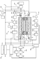
- FIG. 1 is a diagram showing a configuration of a carbon dioxide electrolysis apparatus according to the first embodiment
- FIG. 2 is a cross-sectional view showing a configuration of an electrolysis cell in the electrolysis apparatus shown in FIG.
- an electrolysis cell 2 includes an electrolysis cell 2, an anode solution supply system 100 that supplies an anode solution to the electrolysis cell 2, a cathode solution supply system 200 that supplies a cathode solution to the electrolysis cell 2, and electrolysis
- a gas supply system 300 that supplies carbon dioxide (CO 2 ) gas to the cell 2
- a product collection system 400 that collects products generated by the reduction reaction in the electrolytic cell 2, and the types and amounts of the collected products
- a control system 500 that controls products and controls refresh operations, a waste liquid collection system 600 that collects cathode solution and anode solution waste, and a refresh material supply that recovers the anode and cathode of the electrolytic cell 2 Part 700.
- the electrolytic cell 2 includes an anode part 10, a cathode part 20, and a separator 30.
- the anode unit 10 includes an anode 11, an anode flow path 12, and an anode current collector plate 13.
- the cathode unit 20 includes a cathode solution channel 21, a cathode 22, a cathode channel 23, and a cathode current collector plate 24. Even if the cathode solution channel 21 is not provided and the separator 30 and the cathode 22 are in contact, the cell resistance is low, which is preferable.
- the separator 30 is disposed so as to separate the anode unit 10 and the cathode unit 20.
- the electrolysis cell 2 is sandwiched between a pair of support plates (not shown) and further tightened with bolts or the like.
- a power supply control unit 40 that supplies current to the anode 11 and the cathode 22 is provided.
- the power control unit 40 is connected to the anode 11 and the cathode 22 through a current introduction member.
- the power supply control unit 40 is not limited to a normal system power supply or a battery, and may include a power source that supplies power generated by renewable energy such as a solar battery or wind power generation.
- the power supply control unit 40 may include the power source and a power controller that controls the voltage between the anode 11 and the cathode 22 by adjusting the output of the power source.
- an electrode on the high potential side during electrolysis of carbon dioxide is defined as an anode
- an electrode on the low potential side is defined as a cathode.
- the anode and the cathode may be switched during a refresh operation.
- the anode 11 causes an oxidation reaction of water (H 2 O) in the anode solution as an electrolytic solution to generate oxygen (O 2 ) and hydrogen ions (H + ), or hydroxylation generated at the cathode portion 20.
- This is an electrode (oxidation electrode) that generates an oxidation reaction of product ions (OH ⁇ ) to generate oxygen (O 2 ) and water (H 2 O).
- the anode 11 preferably has a first surface 11 a that contacts the separator 30 and a second surface 11 b that faces the anode flow path 12. The first surface 11 a of the anode 11 is in close contact with the separator 30.
- the anode flow path 12 supplies an anode solution to the anode 11, and is constituted by pits (grooves / recesses) provided in the first flow path plate 14.
- the anode solution flows through the anode channel 12 so as to be in contact with the anode 11.
- the anode current collector plate 13 is in electrical contact with the surface of the first flow path plate 14 constituting the anode flow path 12 on the side opposite to the anode 11.
- the anode 11 and the separator 30 are in close contact.
- Oxygen (O 2 ) is generated at the anode 11.
- bubbles of oxygen (O 2 ) gas generated at the anode 11 are generated. It may stay in the anode solution flow path, and the cell resistance between the anode and the separator (ion exchange membrane or the like) may increase, thereby increasing the voltage fluctuation of the anode.
- the anode flow path 12 is not disposed between the anode 11 and the separator 30, but the anode 11 and the separator 30 are brought into close contact with each other, so that the oxygen gas generated at the anode 11 and the anode solution are anoded. It is discharged to the flow path 12. As a result, the retention of oxygen gas between the anode 11 and the separator 30 is prevented, and cell voltage fluctuations due to anode voltage fluctuations can be suppressed.
- the first flow path plate 14 is provided with a solution inlet and a solution outlet, not shown, and the anode solution is introduced by the anode solution supply system 100 through the solution inlet and the solution outlet. And discharged. It is preferable to use a material having low chemical reactivity and high conductivity for the first flow path plate 14. Examples of such materials include metal materials such as Ti and SUS, carbon, and the like.
- the anode flow path 12 is preferably provided with a plurality of lands (projections) 15.
- the land 15 is provided for mechanical holding and electrical conduction.
- the lands 15 are preferably provided in a staggered manner in order to make the flow of the anode solution uniform.
- the anode flow path 12 meanders by such a land 15. Further, in order to discharge the anode solution mixed with oxygen (O 2 ) gas satisfactorily, it is preferable that the lands 15 are alternately provided in the anode channel 12 and the anode channel 12 is meandered.
- the anode 11 can oxidize water (H 2 O) to generate oxygen and hydrogen ions, or oxidize hydroxide ions (OH ⁇ ) to generate water and oxygen. It is preferable to be mainly composed of a catalyst material (anode catalyst material) capable of reducing the overvoltage of the catalyst.
- Such catalyst materials include metals such as platinum (Pt), palladium (Pd), and nickel (Ni), alloys and intermetallic compounds containing these metals, manganese oxide (Mn—O), iridium oxide (Ir— O), nickel oxide (Ni—O), cobalt oxide (Co—O), iron oxide (Fe—O), tin oxide (Sn—O), indium oxide (In—O), ruthenium oxide (Ru—O) Binary metal oxides such as lithium oxide (Li—O) and lanthanum oxide (La—O), Ni—Co—O, Ni—Fe—O, La—Co—O, Ni—La—O, Sr Examples thereof include ternary metal oxides such as —Fe—O, quaternary metal oxides such as Pb—Ru—Ir—O and La—Sr—Co—O, and metal complexes such as Ru complexes and Fe complexes.
- metals such as platinum (Pt), palladium (Pd), and nickel (Ni), alloys
- the cathode 22 may contain the catalyst material. Further, when platinum, nickel, iron, or the like is used, water can be generated by oxidizing water and reducing oxygen. For this reason, it is possible to efficiently oxidize and reduce water by using these alloys and mixtures.
- the anode 11 is a base structure having a porous structure such as a mesh material, a punching material, a porous body, and a metal fiber sintered body capable of moving an anode solution and ions between the separator 30 and the anode flow path 12. It has materials.
- the base material may be composed of a metal material such as titanium (Ti), nickel (Ni), iron (Fe), or an alloy containing at least one of these metals (for example, SUS), or the anode catalyst described above. You may comprise with material.
- an oxide is used as the anode catalyst material, it is preferable to form a catalyst layer by adhering or laminating the anode catalyst material on the surface of the base material made of the metal material.
- the anode catalyst material preferably has nanoparticles, nanostructures, nanowires and the like in order to enhance the oxidation reaction.
- a nanostructure is a structure in which nanoscale irregularities are formed on the surface of a catalyst material.
- the cathode 22 causes a reduction reaction of carbon dioxide (CO 2 ) and a reduction reaction of a carbon compound generated thereby, and carbon monoxide (CO), methane (CH 4 ), ethane (C 2 H 6 ), ethylene It is an electrode (reduction electrode) that produces carbon compounds such as (C 2 H 4 ), methanol (CH 3 OH), ethanol (C 2 H 5 OH), and ethylene glycol (C 2 H 6 O 2 ).
- a side reaction that generates hydrogen (H 2 ) may occur simultaneously with the reduction reaction of carbon dioxide (CO 2 ) and the reduction reaction of water (H 2 O).
- the cathode 22 has a first surface 22 a facing the cathode solution channel 21 and a second surface 22 b facing the cathode channel 23.
- the cathode solution channel 21 is disposed between the cathode 22 and the separator 30 so that the cathode solution as an electrolytic solution is in contact with the cathode 22 and the separator 30.
- the cathode solution channel 21 is configured by an opening provided in the second channel plate 25.
- the second flow path plate 25 is provided with a solution inlet and a solution outlet, not shown, and the cathode solution is introduced by the cathode solution supply system 200 through the solution inlet and the solution outlet. And discharged.
- the cathode solution flows through the cathode solution channel 21 so as to be in contact with the cathode 22 and the separator 30.
- a material having low chemical reactivity and no electrical conductivity examples include insulating resin materials such as acrylic resin, polyether ether ketone (PEEK), and fluorine resin.
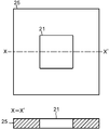
- a land (convex portion) 26 may be provided in the cathode solution flow channel 21 as shown in FIG.
- the land 26 of the cathode solution channel 21 is provided at the center of the cathode solution channel 21, and the bridge portion 27 is thinner than the land 26 so as not to hinder the flow of the cathode solution in the cathode solution channel 21. 2 of the flow path plate 25.
- the lands 26 are provided in the cathode solution channel 21, it is preferable that the number of lands 26 is small in order to reduce the cell resistance.
- the cathode channel 23 is configured by pits (grooves / recesses) provided in the third channel plate 28.
- the third channel plate 28 constituting the cathode channel 23 is preferably made of a material having low chemical reactivity and high conductivity. Examples of such materials include metal materials such as Ti and SUS, carbon, and the like.
- the first flow path plate 14, the second flow path plate 25, and the second flow path plate 28 are provided with solution and gas inlets and outlets (not shown) and screw holes for tightening. Etc. are provided. In addition, packing not shown is sandwiched between the flow path plates 14, 25, and 28 as necessary.
- the third flow path plate 28 is provided with a gas inlet and a gas outlet that are not shown, and the gas supply system 300 passes through the gas inlet and the gas outlet through the CO 2 gas or CO 2.
- 2 gas (collectively, sometimes simply referred to as CO 2 gas) is introduced and discharged.
- the CO 2 gas flows through the cathode channel 23 so as to be in contact with the cathode 22.
- the cathode flow path 23 is preferably provided with a plurality of lands (projections) 29.
- the land 29 is provided for mechanical holding and electrical conduction.
- the lands 29 are preferably provided in a staggered manner, whereby the cathode channel 23 meanders in the same manner as the anode channel 12.
- the cathode current collector plate 24 is in electrical contact with the surface of the third flow path plate 28 opposite to the cathode 22.
- the contact area between the anode 11 and the first flow path plate 14 constituting the anode flow path 12 in addition, the contact area between the cathode 22 and the third flow path plate 28 constituting the cathode flow path 23 can be increased.
- the land 26 in the cathode solution channel 21 the contact area between the cathode 22 and the second channel plate 25 constituting the cathode solution channel 21 can be increased.
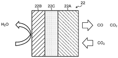
- the cathode 22 has a gas diffusion layer 22A and a cathode catalyst layer 22B provided thereon.
- a porous layer 22C denser than the gas diffusion layer 22A may be disposed between the gas diffusion layer 22A and the cathode catalyst layer 22B.
- the gas diffusion layer 22A is disposed on the cathode channel 23 side, and the cathode catalyst layer 22B is disposed on the cathode solution channel 21 side.
- the cathode catalyst layer 22B may enter the gas diffusion layer 22A.
- the cathode catalyst layer 22B preferably has catalyst nanoparticles, catalyst nanostructures, and the like.
- the gas diffusion layer 22A is made of, for example, carbon paper, carbon cloth, etc., and is subjected to water repellent treatment.
- the porous layer 22C is composed of a porous body having a pore diameter smaller than that of carbon paper or carbon cloth.
- cathode solution and ions are supplied and discharged from the cathode solution channel 21 in the cathode catalyst layer 22B.
- CO 2 gas is supplied from the cathode channel 23, and the product of the CO 2 gas reduction reaction is discharged.
- CO 2 gas reaches the cathode catalyst layer 22B mainly by gas diffusion.
- the reduction reaction of CO 2 and the reduction reaction of the carbon compound produced thereby occur near the boundary between the gas diffusion layer 22A and the cathode catalyst layer 22B or near the cathode catalyst layer 22B that has entered the gas diffusion layer 22A.
- the gaseous product is mainly discharged from the cathode channel 23, and the liquid product is mainly discharged from the cathode solution channel 21.
- the cathode catalyst layer 22B can reduce carbon dioxide to produce a carbon compound, and if necessary, reduce the carbon compound produced thereby to produce a carbon compound. It is preferable to use a catalyst material (cathode catalyst material) that can be reduced.
- a catalyst material cathode catalyst material
- Such materials include gold (Au), silver (Ag), copper (Cu), platinum (Pt), palladium (Pd), nickel (Ni), cobalt (Co), iron (Fe), manganese (Mn ), Titanium (Ti), cadmium (Cd), zinc (Zn), indium (In), gallium (Ga), lead (Pb), tin (Sn) and other metals, alloys containing at least one of these metals, Examples thereof include metal materials such as intermetallic compounds, carbon materials such as carbon (C), graphene, CNT (carbon nanotubes), fullerene and ketjen black, and metal complexes such as Ru complexes and Re complexes.
- the anode 11 may contain the above catalyst material.
- Various shapes such as a plate shape, a mesh shape, a wire shape, a particle shape, a porous shape, a thin film shape, and an island shape can be applied to the cathode catalyst layer 22B.
- the cathode catalyst material constituting the cathode catalyst layer 22B includes the above-described metal material nanoparticles, metal material nanostructures, metal material nanowires, or metal material nanoparticles described above such as carbon particles, carbon nanotubes, and graphene. It is preferable to have a composite supported on a carbon material. By applying catalyst nanoparticles, catalyst nanostructures, catalyst nanowires, catalyst nanosupport structures, etc. as the cathode catalyst material, the reaction efficiency of the carbon dioxide reduction reaction at the cathode 22 can be increased.
- the separator 30 is configured by an ion exchange membrane or the like that can move ions between the anode 11 and the cathode 22 and can separate the anode portion 10 and the cathode portion 20.
- the ion exchange membrane for example, a cation exchange membrane such as Nafion or Flemion, or an anion exchange membrane such as Neoceptor or Selemion can be used.
- the separator 30 is preferably composed of an anion exchange membrane.
- a glass filter, a porous polymer membrane, a porous insulating material, or the like may be applied to the separator 30 as long as it is a material that can move ions between the anode 11 and the cathode 22. May be.
- the anode solution and the cathode solution as the electrolytic solution are preferably solutions containing at least water (H 2 O). Since carbon dioxide (CO 2 ) is supplied from the cathode channel 23, the cathode solution may or may not contain carbon dioxide (CO 2 ). The same solution may be applied to the anolyte solution and the catholyte solution, or different solutions may be applied. Examples of the solution containing H 2 O used as the anode solution and the cathode solution include an aqueous solution containing an arbitrary electrolyte.
- aqueous solution containing an electrolyte examples include hydroxide ions (OH ⁇ ), hydrogen ions (H + ), potassium ions (K + ), sodium ions (Na + ), lithium ions (Li + ), chloride ions (Cl ⁇ ), Bromide ion (Br ⁇ ), iodide ion (I ⁇ ), nitrate ion (NO 3 ⁇ ), sulfate ion (SO 4 2 ⁇ ), phosphate ion (PO 4 2 ⁇ ), borate ion (BO) 3 3- ) and an aqueous solution containing at least one selected from hydrogencarbonate ions (HCO 3 ⁇ ).
- an alkaline solution in which an electrolyte such as potassium hydroxide or sodium hydroxide is dissolved at a high concentration as the anode solution and the cathode solution.
- the catholyte solution, and cations such as imidazolium ions, pyridinium ions, BF 4 - with consists salts with anions such, the ionic liquid or an aqueous solution thereof in a liquid state in a wide temperature range - or PF 6 Also good.
- Other cathode solutions include amine solutions such as ethanolamine, imidazole and pyridine, or aqueous solutions thereof.
- the amine may be any of primary amine, secondary amine, and tertiary amine.
- An anode solution is supplied from the anode solution supply system 100 to the anode flow path 12 of the anode unit 10.
- the anode solution supply system 100 circulates the anode solution so that the anode solution flows through the anode channel 12.
- the anode solution supply system 100 includes a pressure control unit 101, an anode solution tank 102, a flow rate control unit (pump) 103, a reference electrode 104, and a pressure gauge 105 so that the anode solution circulates in the anode flow path 12. It is configured.
- the anode solution tank 102 is connected to a gas component collection unit (not shown) that collects a gas component such as oxygen (O 2 ) contained in the circulating anode solution.
- the anode solution is introduced into the anode channel 12 with the flow rate and pressure controlled by the pressure control unit 101 and the flow rate control unit 103.
- the cathode solution is supplied from the cathode solution supply system 200 to the cathode solution channel 21 of the cathode unit 20.
- the cathode solution supply system 200 circulates the cathode solution so that the cathode solution flows through the cathode solution channel 21.
- the cathode solution supply system 200 includes a pressure control unit 201, a cathode solution tank 202, a flow rate control unit (pump) 203, a reference electrode 204, and a pressure gauge 205, and the cathode solution circulates in the cathode solution channel 21. It is configured as follows.
- the cathode solution tank 202 is connected to a gas component collection unit 206 that collects gas components such as carbon monoxide (CO) contained in the circulating cathode solution.
- the cathode solution is introduced into the cathode solution channel 21 with the flow rate and pressure controlled by the pressure control unit 201 and the flow rate control unit 203.
- the cathode flow path 23 is supplied with CO 2 gas from the gas supply system 300.
- the gas supply system 300 includes a CO 2 gas cylinder 301, a flow rate control unit 302, a pressure gauge 303, and a pressure control unit 304.
- the CO 2 gas is introduced into the cathode channel 23 while the flow rate and pressure are controlled by the flow rate control unit 302 and the pressure control unit 304.
- the gas supply system 300 is connected to a product collection system 400 that collects products in the gas flowing through the cathode channel 23.
- the product collection system 400 includes a gas-liquid separation unit 401 and a product collection unit 402. Reduction products such as CO and H 2 contained in the gas flowing through the cathode channel 23 are accumulated in the product collection unit 402 via the gas-liquid separation unit 401.
- the anode solution and the cathode solution circulate through the anode channel 12 and the cathode solution channel 21 during the electrolytic reaction operation.
- the anode solution and the cathode solution are supplied to the waste liquid collection system 600 so that the anode 11, the anode channel 12, the cathode 22, the cathode solution channel 21 and the like are exposed from the anode solution and the cathode solution. Discharged.
- the waste liquid collection system 600 includes a waste liquid collection tank 601 connected to the anode flow path 12 and the cathode solution flow path 21.
- the anolyte or catholyte waste liquid is collected in a waste liquid collection tank 601 by opening and closing a valve (not shown). The opening and closing of the valves and the like are collectively controlled by the control system 500.
- the waste liquid collection tank 601 also functions as a rinsing liquid collection unit supplied from the refresh material supply unit 700. Further, a gaseous substance supplied from the refreshing material supply unit 700 and partially including a liquid substance is also collected in the waste liquid collection tank 601 as necessary.
- the refresh material supply unit 700 includes a gaseous substance supply system and a rinse liquid supply system.
- the gaseous substance supply system includes a gas tank 711 serving as a supply source of gaseous substances such as air, carbon dioxide, oxygen, nitrogen, and argon, and a control unit 712 that controls the supply pressure and flow rate of the gaseous substance.
- the rinse liquid supply system includes a tank 70 that serves as a supply source of a rinse liquid such as water.
- the gaseous substance supply system and the rinse liquid supply system are connected to the anode flow path 12, the cathode solution flow path 21, and the cathode flow path 23 through piping.
- the tank 70 is connected to the cathode channel 23, for example.
- the tank 70 stores a rinsing liquid.
- the tank 70 may contain an oxidation product such as water together with the rinse liquid.
- the carbon dioxide electrolysis apparatus 1 has a valve 71 or a valve 74.
- the valve 71 controls the connection between the channel through which the carbon dioxide supplied from the gas supply system 300 flows and the cathode channel 23 by an opening / closing operation.
- the valve 72 controls the connection between the cathode channel 23 and the channel through which the reduction product flows from the cathode channel 23 to the product collection system 400 by the opening / closing operation.
- the valve 73 controls, for example, the connection between the channel through which the anode solution flows and the anode channel 12 by an opening / closing operation.
- the valve 74 controls the connection between the anode channel 12 and the channel through which the oxidation product flows from the anode channel 12 to the product collection system 400, for example, by an opening / closing operation. Opening and closing of the valves including the valves 71 to 74 are collectively controlled by the control system 500.
- the control system 500 may control a valve for connecting the cathode solution channel 21 with a channel for flowing the cathode solution into or out of the cathode solution channel 21.
- a part of the reduction product accumulated in the product collection unit 402 is sent to the reduction performance detection unit 501 of the control system 500.
- the reduction performance detection unit 501 detects the production amount and ratio of each product such as CO and H 2 in the reduction product.
- the detected production amount and ratio of each product are input to the data collection / control unit 502 of the control system 500.
- the data collection / control unit 502 includes electrical data such as cell voltage, cell current, cathode potential, anode potential, and the like inside the anode solution channel and cathode solution channel. Data such as pressure and pressure loss is collected and sent to the refresh control unit 503.
- the data collection / control unit 502 includes the power control unit 40, the pressure control unit 101 and the flow rate control unit 103 of the anode solution supply system 100, the pressure control unit 201 and the flow rate of the cathode solution supply system 200.
- the control unit 203, the flow rate control unit 302 and the pressure control unit 304 of the gas supply system 300, and the control unit 712 of the refreshing material supply unit 700 are electrically connected via bidirectional signal lines, some of which are not shown. These are controlled collectively.
- Each pipe is provided with a valve (not shown), and the opening / closing operation of the valve is controlled by a signal from the data collection / control unit 502.
- the data collection / control unit 502 may control the operation of the above components during the electrolysis operation.
- the refresh control unit 503 includes a power control unit 40, a flow rate control unit 103 of the anode solution supply system 100, a flow rate control unit 203 of the cathode solution supply system 200, a flow rate control unit 302 of the gas supply system 300, and a refresh material supply unit 700.
- the control unit 712 and the flow rate control unit 722 are electrically connected via bidirectional signal lines, some of which are not shown, and are collectively controlled.
- Each pipe is provided with a valve (not shown), and the opening / closing operation of the valve is controlled by a signal from the refresh control unit 503.
- the refresh control unit 503 may control the operation of the above components during the electrolysis operation.
- the refresh control unit 503 and the data collection / control unit 502 may be configured by a single control unit.
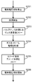
- a startup step S ⁇ b> 101 of the electrolysis apparatus 1 is performed.
- the startup process S101 of the electrolyzer 1 the following operation is performed.
- the flow rate and pressure are controlled by the pressure control unit 101 and the flow rate control unit 103, and the anolyte solution is introduced into the anode flow path 12.
- the cathode solution supply system 200 the flow rate and pressure are controlled by the pressure control unit 201 and the flow rate control unit 203, and the cathode solution is introduced into the cathode solution channel 21.
- the flow rate and pressure are controlled by the flow rate control unit 302 and the pressure control unit 304 to introduce CO 2 gas into the cathode flow path 23.
- the CO 2 electrolysis operation step S102 is performed.
- application of an electrolysis voltage by the power supply control unit 40 of the electrolysis apparatus 1 in which the start-up step S101 has been performed is started, and a voltage is applied between the anode 11 and the cathode 22 to generate a current. Is supplied.
- a current is passed between the anode 11 and the cathode 22, the following oxidation reaction near the anode 11 and reduction reaction near the cathode 22 occur.
- CO carbon monoxide
- the carbon compound as a reduction product of carbon dioxide is not limited to carbon monoxide, and the organic compounds described above may be used. Other carbon compounds may be used.
- the reaction process by the electrolytic cell 2 it is considered that hydrogen ions (H + ) are mainly generated and hydroxide ions (OH ⁇ ) are mainly generated. It is not limited to crab.
- the H + generated in the anode 11 moves in the anode solution existing in the anode 11, the separator 30, and the cathode solution in the cathode solution channel 21, and reaches the vicinity of the cathode 22.
- a reduction reaction of carbon dioxide (CO 2 ) is caused by electrons (e ⁇ ) based on the current supplied from the power supply control unit 40 to the cathode 22 and H + moved to the vicinity of the cathode 22.
- CO 2 supplied from the cathode flow path 23 to the cathode 22 is reduced to generate CO. 2CO 2 + 4H + + 4e ⁇ ⁇ 2CO + 2H 2 O (2)
- the CO 2 reduction reaction is considered to occur near the boundary between the gas diffusion layer 22A and the cathode catalyst layer 22B, as described above.
- the cathode solution flowing through the cathode solution channel 21 penetrates to the gas diffusion layer 22A, or the cathode catalyst layer 22B becomes excessive in water, so that the amount of CO generated by the CO 2 reduction reaction is reduced. Inconveniences such as an increase in cell voltage occur.
- Such cell performance degradation of the electrolytic cell 2 is caused by uneven distribution of ions and residual gas in the vicinity of the anode 11 and the cathode 22, excess water in the cathode catalyst layer 22B, precipitation of electrolyte in the cathode 22 and anode 11, and further anode flow. It is also caused by the deposition of electrolyte in the channel 12 and the cathode solution channel 21.
- salt may be deposited on the cathode solution flow path 21 and the gas diffusion layer 22A due to the electrolysis operation, and the cell performance may be deteriorated due to the blockage of the flow path or the gas diffusibility.
- ions move between the anode 11 and the cathode 22 via the separator 30 or the ion exchange membrane, and the ions react with the gas component.
- a potassium hydroxide solution is used as the anode solution and carbon dioxide gas is used as the cathode gas
- potassium ions move from the anode 11 to the cathode 22, and the ions react with carbon dioxide to cause potassium bicarbonate, potassium carbonate, etc.
- salt may be deposited on the cathode solution flow path 21 and the gas diffusion layer 22A due to the electrolysis operation, and the cell performance may be deteriorated due to the blockage of the flow path or the gas diffusibility.
- ions move between the anode 11 and the cathode 22 via the separator 30 or the ion exchange membrane,
- the salt precipitates in the cathode solution channel 21 and the gas diffusion layer 22A when the salt is below the solubility. Due to the blockage of the flow path, the uniform gas flow is prevented throughout the cell, and the cell performance is degraded. In particular, when a plurality of cathode solution flow paths 21 are provided, the cell performance is significantly reduced. Note that the performance of the cell itself may be improved by partially increasing the gas flow rate. This is because the cell performance is improved by increasing the gas component supplied to the catalyst or increasing the gas diffusibility by increasing the gas pressure. In order to detect such a decrease in cell performance, step S103 is performed to determine whether the cell performance meets the required standard.
- the data collection / control unit 502 for example, periodically or continuously generates the production amount and ratio of each product, the cell voltage of the electrolytic cell 2, the cell current, the cathode potential, the anode potential, and the anode channel 12 Cell performance such as internal pressure and pressure inside the cathode solution channel 21 is collected. Further, the data collection / control unit 502 has cell performance requirement standards set in advance, and determines whether the collected data satisfies the set requirement criteria. If the collected data satisfies the set required criteria, the CO 2 electrolysis operation S102 is continued without stopping the CO 2 electrolysis (S104). If the collected data does not satisfy the set request criteria, the refresh operation step S105 is performed.
- the cell performance collected by the data collection / control unit 502 includes, for example, an upper limit value of the cell voltage when a constant current is passed through the electrolytic cell 2, a lower limit value of the cell current when a constant voltage is applied to the electrolytic cell 2, and CO 2. It is defined by parameters such as the Faraday efficiency of the carbon compound produced by the reduction reaction. Here, the Faraday efficiency is defined as the ratio of the current that contributed to the formation of the target carbon compound to the total current flowing through the electrolytic cell 2.
- the refresh operation step S105 may be performed when the upper limit value of the cell voltage when a constant current is passed reaches 150% or more, preferably 120% or more of the set value.
- the refresh operation step S105 may be performed when the lower limit value of the cell current when the constant voltage is applied reaches 50% or less, preferably 80% or less of the set value. In order to maintain the production amount of the reduction product such as the carbon compound, the refresh operation step S105 may be performed when the Faraday efficiency of the carbon compound is 50% or less, preferably 80% or less than the set value.
- the refresh operation step S105 is performed. Further, two or more of the above parameters may be combined to set the cell performance requirement standard.
- the refresh operation step S105 may be performed when both the cell voltage and the Faraday efficiency of the carbon compound do not satisfy the required standards.
- the refresh operation step S105 is performed when at least one of the cell performances does not satisfy the required standard. In order to stably perform the CO 2 electrolysis operation step S102, the refresh operation step S105 is preferably performed at intervals of, for example, 1 hour or more.
- the cell pressure pressure inside the anode flow path 12, pressure inside the cathode solution flow path 21, etc. is set as one of the parameters for defining the required criteria. It is preferable to detect the precipitation and perform a refresh operation.
- the determination of the necessity of the refresh operation is not only the detection of salt due to the change in cell voltage, current value, and cell pressure, but also when the anode 11 and the cathode 22 are separated by the separator 30.
- Gas-liquid separation performance that is, liquid between the anode 11 and the cathode 22, the amount of gas movement, the amount of product, the voltage difference with the reference electrode, and the estimated value of the Faraday efficiency from these parameters Judgment etc.
- the Faraday efficiency from each parameter value and the necessity of the refresh operation can be comprehensively determined from the parameters described later as the necessity of the refresh operation, and combinations of values and calculation methods are arbitrary.
- the necessity of the refresh operation may be determined based on the degree of flooding estimated from each cell data or pressure change according to the operation method for detecting flooding performance. Further, the operation time of the electrolysis cell 2 may be taken into consideration.
- the operation time is not limited to the operation time after the start of operation, but may be an integrated value of the previous operation time, a continuous time, an operation time after the refresh operation, or an integrated voltage value, time, and current value. It may be a calculation value such as multiplication of time and time, and the combination and calculation method are arbitrary. In addition, the calculated values of these combinations are preferable because differences due to the operation method of the electrolysis cell 2 are taken into consideration rather than simply determination based on the duration or the like. Furthermore, a fluctuation value of current or voltage, a pH value of the electrolyte, a change value, an oxygen generation amount, or a fluctuation amount may be used.
- each parameter for determining the necessity of the refresh operation is that each data of the electrolysis cell 2 is collected through an electronic network, and the big data is collected by the data collection / control unit 502 and the analysis unit 504 of a plurality of cells. Necessary parameters are derived by analysis and analysis such as machine learning, and the refresh control unit 503 is made to update the cell performance requirement criteria defined by each parameter for determining the necessity of refresh, and always performs the best refresh operation. It can be carried out.
- the refresh operation step S105 is performed, for example, according to the flowchart shown in FIG. First, the application of the electrolysis voltage by the power supply control unit 40 is stopped, and the CO 2 reduction reaction is stopped (S201). At this time, the application of the electrolytic voltage is not necessarily stopped. Next, the cathode solution and the anode solution are discharged from the cathode solution channel 21 and the anode channel 12 (S202). At this time, it is not always necessary to discharge at least one of the cathode solution and the anode solution.
- valve 71 and the valve 72 are closed (S203).
- the valve 73 and the valve 74 may be opened or closed.
- the state of the electrolytic cell 2 at this time is shown in FIG.
- FIG. 12 shows the electrolysis cell 2, the tank 70, the flow paths 701 to 704, and the valves 71 to 74.
- the anode channel 12 and the cathode channel 23 are illustrated as being divided into a plurality of parts, but are assumed to be continuous.
- the valve connected to the cathode solution channel 21 may be closed in step S203.
- the channel 701 is a channel through which carbon dioxide supplied from the gas supply system 300 flows.
- the channel 702 is a channel through which the reduction product flows in the product collection system 400.
- the channel 703 is a channel through which the anode solution flows.
- the channel 704 is a channel through which the oxidation product flows in the product collection system 400.
- the valve 71 can connect the cathode channel 23 and the channel 701.
- the valve 72 can connect the cathode channel 23 and the channel 702.
- the valve 73 can connect the anode channel 12 and the channel 703.
- the valve 74 can connect the anode channel 12 and the channel 704.
- the cathode channel 23 is disconnected from the channel 701 and the channel 702, respectively.
- the carbon dioxide remaining inside the cathode channel 23 is absorbed by the rinsing liquid 70a accommodated in the tank 70, and the inside of the cathode channel 23 is depressurized.
- the rinsing liquid 70a is supplied to the inside of the cathode channel 23 whose pressure has been reduced, and for example, ions and impurities attached to the inside of the cathode channel 23 and the cathode catalyst layer 22B can be removed.
- the pressure is excessively reduced, and the rinsing liquid 70a may not be supplied from the tank 70 to the cathode flow path 23.
- a valve for connecting the cathode channel 23 and the tank 70 may be provided in order to suppress a decrease in the amount of carbon dioxide absorbed into the rinsing liquid. For example, by closing the valve during the electrolysis operation and opening the valve in step S203 to connect the cathode channel 23 and the tank 70, it is possible to suppress a decrease in the amount of carbon dioxide absorbed in the rinse liquid due to the electrolysis operation. Further, the inside of the tank 70 may be slightly pressurized so that the gas does not enter the tank 70 during the electrolysis operation.
- gas is supplied to the anode channel 12 and the cathode channel 23 (S204), and the cathode 22 and the anode 11 are dried. At this time, the gas may be supplied also to the cathode solution channel 21.
- the rinsing liquid is supplied to the anode flow path 12 and the cathode flow path 23, the degree of saturation of water in the gas diffusion layer 22A increases, and the output decreases due to gas diffusibility.
- the gas is preferably supplied immediately after circulation of the rinse liquid, and at least within 5 minutes after completion of the supply of the rinse liquid. This is because the output decrease due to the increase in water saturation is large. For example, if the refresh operation is performed every other hour, the output during the refresh operation for 5 minutes is 0 V or significantly less, so the output is 5/60 of the output. You may lose.
- the valves 71 to 74 are opened to introduce the anode solution into the anode channel 12 and CO 2 gas into the cathode channel 23 (S205).
- a valve connected to the cathode solution channel 21 may be opened.
- the application of the electrolysis voltage is resumed between the anode 11 and the cathode 22 by the power supply control unit 40, and the CO 2 electrolysis operation is resumed (S206). Note that if the application of the electrolytic voltage is not stopped in S201, the resuming operation is not performed.
- a gas may be used, or a rinse solution may be used.
- the rinsing liquid is preferably water, more preferably water having an electric conductivity of 1 mS / m or less, and further preferably water having a conductivity of 0.1 mS / m or less.
- an acidic rinse solution such as sulfuric acid, nitric acid, hydrochloric acid or the like having a low concentration may be supplied, thereby dissolving the electrolyte.
- an acidic rinse solution such as sulfuric acid, nitric acid, hydrochloric acid or the like having a low concentration
- a step of supplying a rinsing solution of water in the subsequent step is performed.
- a water rinse solution supply step it is preferable to carry out a water rinse solution supply step in order to prevent the additive contained in the rinse solution from remaining.
- an acid or alkali rinse is preferred for refreshing the ion exchange resin.
- This has the effect of discharging cations and anions substituted for protons and OH ⁇ in the ion exchange resin.
- gas is supplied between the supply of a plurality of rinse liquids so that the acid and alkali rinse liquids are alternately circulated, a combination with water having an electric conductivity of 1 mS / m or less, and the rinse liquids are not mixed. It is preferable to do.
- water is produced when CO is produced from CO 2 and protons by reduction.
- the water discharged from the cathode 22 at this time may be separated and stored by gas-liquid separation. In this way, it is not necessary to newly supply a rinse liquid from the outside, which is advantageous in terms of the system.
- the water may be supplied to the cathode solution channel 21 by changing the potential to increase the reaction current and increasing the amount of water generated. This eliminates the need for pipes and pumps for use as a tank of the generated water and a rinse liquid, and is an effective system configuration.
- the electrolytic solution or the rinsing solution of the anode 11 is hydrolyzed and generated by the catalyst from protons or OH ⁇ ions that have moved to the counter electrode.
- the refresh operation may be performed with water.
- Nafion is used as an ion exchange membrane in an electrolytic cell that reduces CO 2 to CO using a gold catalyst
- water is circulated through the cathode 22 and potential is applied to the cell to perform water decomposition.
- the proton moved to 22 reacts with oxygen by a catalyst to produce water.
- a refresh operation can be performed with the generated water.
- a refresh operation may be performed in which hydrogen gas is generated by supplying a gas not containing oxygen to the cathode 22 or by stopping the gas supply, and the cathode 22 is dried by the generated hydrogen.
- the catalyst can be refreshed by the reducing power of protons and hydrogen.
- the gas used in the gas supply and flow step S204 preferably includes at least one of air, carbon dioxide, oxygen, nitrogen, and argon. Furthermore, it is preferable to use a gas with low chemical reactivity. From these points, air, nitrogen, and argon are preferably used, and more preferably nitrogen and argon.
- the supply of the rinsing liquid and gas for refreshing is not limited to the cathode solution flow path 21 and the anode flow path 12, and the surface of the cathode 22 that contacts the cathode flow path 23 is washed. May be supplied. In order to dry the cathode 22 also from the side in contact with the cathode channel 23, it is effective to supply gas to the cathode channel 23.
- the refresh rinse liquid and gas are supplied to only one of the anode unit 10 and the cathode unit 20. Also good.
- the Faraday efficiency of the carbon compound varies depending on the contact region between the cathode solution and CO 2 in the gas diffusion layer 22A and the cathode catalyst layer 22B of the cathode 22. In such a case, the Faraday efficiency of the carbon compound may be recovered only by supplying a refreshing rinsing liquid or gas only to the cathode portion 20.
- the electrolytic solution may tend to be deposited on one of the anode portion 10 and the cathode portion 20.
- a refreshing rinse liquid and gas may be supplied to only one of the anode unit 10 and the cathode unit 20.
- the cell performance may be recovered by simply drying the anode 11 and the cathode 22. In such a case, only the refreshing gas may be supplied to at least one of the anode unit 10 and the cathode unit 20.
- the refresh operation step S105 can be variously changed in accordance with the operation state and tendency of the electrolysis apparatus 1.
- the CO 2 electrolysis operation step S102 is continued or refreshed based on whether the cell performance of the electrolysis cell 2 satisfies the required standard. It is determined whether step S105 is performed.
- the cathode solution which causes a reduction in cell performance, enters the gas diffusion layer 22A, excess water in the cathode catalyst layer 22B, the vicinity of the anode 11 and the cathode 22
- the distribution of ions and residual gas in the cathode, the deposition of electrolyte in the cathode 22, the anode 11, the anode channel 12, and the cathode solution channel 21 are removed.
- the cell performance of the electrolysis cell 2 can be recovered by restarting the CO 2 electrolysis operation step S102 after the refresh operation step S105.
- the CO 2 electrolysis operation step S102 and the refresh operation step S105 based on the cell performance requirement criteria, it is possible to maintain the CO 2 electrolysis performance of the electrolysis apparatus 1 for a long time.
- a refresh voltage may be applied between the anode 11 and the cathode 22. Thereby, ions and impurities attached to the cathode catalyst layer 22B can be removed.
- a refresh voltage is applied so as to be mainly oxidized, impurities such as ions and organic substances attached to the catalyst surface are oxidized and removed. Further, by performing this treatment in the rinsing liquid, not only refreshing of the catalyst, but also ion substituted in the ion exchange resin can be removed when an ion exchange membrane is used as the separator 30.
- the refresh voltage is preferably from ⁇ 2.5 V to 2.5 V, for example.
- the refresh voltage range is preferably as narrow as possible, for example, more preferably ⁇ 1.5V to 1.5V.
- the refresh voltage may be cyclically applied so that ion and impurity oxidation treatment and reduction treatment are alternately performed. Thereby, regeneration of an ion exchange resin and regeneration of a catalyst can be accelerated.
- the refresh operation may be performed by applying a voltage having a value equivalent to the electrolysis voltage during the electrolysis operation as the refresh voltage. In this case, the configuration of the power control unit 40 can be simplified.
- the refresh operation step S105 is not limited to the content shown in the flowchart shown in FIG.
- FIG. 13 is a flowchart showing another example of the refresh operation step S105.
- the refresh operation step S105 is performed by further using the flow path 705 and the valve 75 in addition to the configuration shown in FIG.
- the flow path 705 is a flow path through which carbon dioxide flows. Note that the channel 705 may be connected to the channel 701.
- the valve 75 can connect the anode channel 12 and the channel 705.
- the application of the electrolytic voltage by the power supply control unit 40 is stopped, and the CO 2 reduction reaction is stopped (S301). At this time, the application of the electrolytic voltage is not necessarily stopped.
- the cathode solution and the anode solution are discharged from the cathode solution channel 21 and the anode channel 12 (S302). At this time, it is not always necessary to discharge at least one of the cathode solution and the anode solution.
- valve 71, the valve 72, and the valve 75 are closed (S303).
- the valve 73 and the valve 74 may be opened or closed.
- the state of the electrolytic cell 2 at this time is shown in FIG.
- valve 73 is closed and the valve 75 is opened (S304). Note that the valve 74 may be opened or closed.
- the state of the electrolytic cell 2 at this time is shown in FIG.
- valves 74 and 75 are closed (S305).
- the state of the electrolytic cell 2 at this time is shown in FIG.
- the anode flow path 12 is disconnected from each of the flow paths 703 to 705.
- carbon dioxide remaining inside the anode flow path 12 and the cathode flow path 23 is absorbed by the rinse liquid 70a in the tank 70, and the inside of the anode flow path 12 and the cathode flow path 23 is decompressed.
- the rinse liquid 70a is supplied to the interior of the anode passage 12 and the cathode passage 23 that have been depressurized, and the ions adhering to the inside of the anode passage 12, the inside of the cathode passage 23, and the cathode catalyst layer 22B Impurities can be removed.
- the subsequent gas flow step S306, the electrolytic solution introduction step S307, and the electrolytic voltage application start step S308 are the same as S204, S205, and S206, respectively, and thus description thereof is omitted.
- FIG. 17 is a flowchart showing another example of the refresh operation step S105.
- the refresh operation step S105 is performed by further using the flow path 706 and the valve 76 in addition to the configuration shown in FIG.
- the flow path 706 is a flow path through which oxygen flows. Note that the channel 706 may be directly or indirectly connected to the channel 704.
- the valve 76 can connect the cathode channel 23 and the channel 706 and connect the anode channel 12 and the channel 706. That is, the valve 76 can switch between the connection between the cathode channel 23 and the channel 706 and the connection between the anode channel 12 and the channel 706.
- the application of the electrolysis voltage by the power supply control unit 40 is stopped, and the CO 2 reduction reaction is stopped (S401). At this time, the application of the electrolytic voltage is not necessarily stopped.
- the cathode solution and the anode solution are discharged from the cathode solution channel 21 and the anode channel 12 (S402). At this time, it is not always necessary to discharge at least one of the cathode solution and the anode solution.
- valves 71 and 76 are closed and the valves 73 and 74 are opened (S403).
- the state of the electrolytic cell 2 at this time is shown in FIG.
- a case where a catalyst that can further reduce oxygen is used for the anode 11 and a catalyst that can further oxidize water is used for the cathode 22 will be described.
- the cathode flow path 23 is disconnected from the flow paths 701 and 702, and the anode flow path 12 and the cathode flow path 23 are disconnected from the flow path 706.
- the valves 73 and 74 are opened, the anode channel 12 is connected to the channels 703 and 704, and the anode solution is supplied to the anode channel 12.
- valve 72 is closed and the valve 76 is opened to connect the cathode channel 23 and the channel 706 (S404).
- the valve 73 and the valve 74 may be opened or closed.
- the state of the electrolytic cell 2 at this time is shown in FIG.
- the cathode channel 23 is disconnected from the channel 702. Further, when the cathode channel 23 and the channel 706 are connected, oxygen is supplied to the cathode channel 23.
- the valve 73 is closed to disconnect the anode flow path 12 from the flow path 703.
- valve 76 is closed and a second electrolytic voltage is applied between the anode and the cathode (S405).
- the anode 11 side has a high potential VL
- the cathode 22 side has a low potential VL lower than the high potential VL.
- the state of the electrolytic cell 2 at this time is shown in FIG.
- the H + generated at the anode 11 moves through the anode flow path 12, the separator 30, the cathode solution flow path 21, and the cathode flow path 23 and reaches the vicinity of the cathode 22.
- the reduction reaction of oxygen (O 2 ) is caused by electrons (e ⁇ ) based on the current supplied from the power supply control unit 40 to the cathode 22 and H + moved to the vicinity of the cathode 22.
- O 2 supplied from the cathode flow path 23 to the cathode 22 is reduced to generate H 2 O.
- a reduction reaction using hydroxide ions as in the above formula (3) may be performed.
- the separator 30 is preferably a porous body.
- oxygen is supplied to the anode channel 12.
- the flow path 706 is connected to the flow path 704
- the oxygen generated in step S ⁇ b> 405 is supplied to the anode flow path 12.
- the valve 76 is closed and the valve 72 is opened, and a third electrolytic voltage is applied between the anode 11 and the cathode 22 (S407).
- the cathode 22 side has a high potential VL
- the anode 11 side has a low potential VL lower than the high potential VL.
- the function of the anode 11 and the function of the cathode 22 are opposite. Note that the values of the potentials VL and VH may be different from the second power supply voltage.
- the state of the electrolytic cell 2 at this time is shown in FIG.
- the H + generated at the cathode 22 moves through the anode channel 12, the separator 30, and the cathode channel 23 and reaches the vicinity of the anode 11.
- the reduction reaction of oxygen (O 2 ) is caused by electrons (e ⁇ ) based on the current supplied from the power supply control unit 40 to the anode 11 and H + moved to the vicinity of the anode 11.
- O 2 supplied from the anode flow path 12 to the anode 11 is reduced to generate H 2 O.
- a reduction reaction using hydroxide ions as in the above formula (3) may be performed.
- ions and impurities attached to the inside of the anode channel 12 can be removed. Note that, by reducing the pressure inside the anode channel 12, the rinse liquid 70 a is supplied to the inside of the anode channel 12, and ions and impurities attached to the inside of the anode channel 12 can be removed.
- the separator 30 is, for example, Nafion
- the separator 30 by removing the impurities, metal ions or the like mixed as impurities are replaced with protons, and the separator 30 can be regenerated.
- This is preferable from the viewpoint of refresh effect and life.
- impurities on the electrode and a regeneration function of the catalyst by oxidation-reduction treatment can be expected. From the above viewpoints, by supplying oxygen-containing gas alternately to the anode and the cathode and repeating the oxidation and reduction, it is possible to obtain the effect of improving the life by the catalyst regeneration function, the separator regeneration function, and the storage effect in the solution. .
- a hydrophilic polytetrafluoroethylene (PTFE) porous body is used to supply the rinsing liquid only to the anode flow path 12, and the anode is formed by a valve or the like (not shown). Apply pressure to the outlet liquid or plug the anode outlet. Then, the rinsing liquid passes through the separator 30 and flows to the cathode 22, and the rinsing liquid flows out from the discharge port of the cathode 22. Thereby, the cathode 22 and the anode 11 can be refreshed simultaneously.
- This configuration is preferable because it eliminates the need for a device for allowing the rinse liquid to flow through the cathode 22, thereby making the device compact and simplifying the system.
- the cathode channel 23 can be washed. At this time, the impurities transferred to the cathode channel 23 can be reduced by the protons moved to the cathode channel 23, and the catalyst and members can be regenerated. Since this configuration does not require a device for supplying the rinsing liquid to the cathode channel 23, the device can be made compact and the system can be simplified. Further, when the air flowing to the cathode is stopped before the subsequent flow of the CO 2 gas, the generated protons react with each other, hydrogen is generated, and the generated water can be pushed out. The oxygen-containing gas is stopped before extruding with CO 2 , and the regeneration function of the catalyst and members by protons can be more effective. This is because since there is no oxygen, other members that are difficult to reduce and each member of the cathode 22 are reduced. Specifically, there are organic impurities and metal oxides. A refreshing effect can be expected by supplying and reacting CO 2 thereafter.
- a liquid channel may be provided in the cathode channel separately from the CO 2 gas.
- This flow path can be used for controlling the temperature of the cell by circulating a liquid in order to recover the heat generated by the cell. If the liquid is in contact with the catalyst layer of the cell, it can be used for humidifying the catalyst layer and the electrolyte membrane, and the humidity can be controlled. This method is preferable because the catalyst layer and the separator 30 can be operated under saturated steam conditions at the cell temperature.
- CO 2 may flow through this flow path, and as described above, the CO 2 gas is absorbed into the rinsing liquid circulated through the solution flow path for refreshing and storage of the cell. Since the rinse liquid can be supplied, it is preferable.
- FIG. 23 is a diagram showing the configuration of the carbon dioxide electrolysis apparatus according to the second embodiment
- FIG. 24 is a cross-sectional view showing the configuration of the electrolysis cell in the electrolysis apparatus shown in FIG.
- the carbon dioxide electrolysis apparatus 1X shown in FIG. 23 is similar to the carbon dioxide electrolysis apparatus 1 according to the first embodiment, and includes an electrolysis cell 2X, an anode solution supply system 100 that supplies an anode solution to the electrolysis cell 2X, and electrolysis.
- Cathode solution supply system 200 that supplies a cathode solution to the cell 2X, a gas supply system 300 that supplies carbon dioxide (CO 2 ) gas to the electrolytic cell 2X, and a product that collects products generated by a reduction reaction in the electrolytic cell 2X
- a product collection system 400 a control system 500 that detects the type and amount of the collected product, and controls the product and refresh operation, and a waste liquid collection system 600 that collects the waste solution of the cathode solution and the anode solution.
- a refresh material supply unit 700 for recovering the anode, cathode, etc. of the electrolytic cell 2X.
- FIG. 23 shows the valves 71 to 74 and the tank 70 as in FIG.
- the carbon dioxide electrolysis apparatus 1X shown in FIG. 23 basically has the same configuration as the electrolysis apparatus 1 shown in FIG. 1 except that the configuration of the electrolysis cell 2X is different.
- the electrolytic cell 2X includes a reaction tank 53 having an anode solution tank 51, a cathode solution tank 52, and a separator 30 that separates the anode solution tank 51 and the cathode solution tank 52.
- the anode solution tank 51 has a solution inlet 54A and a solution outlet 55A connected to the anode solution supply system 100, and a gas inlet 56A and a gas outlet 57A.
- An anode solution is introduced into and discharged from the anode solution supply system 100 into the anode solution tank 51.
- the anode 11 is arranged in the anode solution tank 51 so as to be immersed in the anode solution.
- the anode 11 is connected to the power supply control unit 40 via the current introduction unit 58A.
- the cathode solution tank 52 has a solution introduction port 54B and a solution discharge port 55B connected to the cathode solution supply system 200, and a gas introduction port 56B and a gas discharge port 57B connected to the gas supply system 300.
- the cathode solution is introduced into and discharged from the cathode solution tank 52 from the cathode solution supply system 200.
- CO 2 gas is introduced into the cathode solution tank 52 from the gas supply system 300, and the gas containing the gaseous product is sent to the product collection system 400.
- the cathode 22 is disposed in the cathode solution tank 52 so as to be immersed in the cathode solution.
- the cathode 22 is connected to the power supply control unit 40 through the current introduction unit 58B.
- the gaseous substance supply system of the refresh material supply unit 700 is connected to the gas introduction port 56A of the anode solution tank 51 and the cathode solution tank 52 gas introduction port 56B via a pipe.
- the rinse liquid supply system of the refresh material supply unit 700 is connected to the solution introduction port 54A of the anode solution tank 51 and the solution introduction port 54B of the cathode solution tank 52 through a pipe.
- the solution discharge port 55A of the anode solution tank 51 and the solution discharge port 55B of the cathode solution tank 52 are connected to the waste liquid collection system 600 through a pipe.
- the gas discharge port 57A of the anode solution tank 51 and the gas discharge port 57B of the cathode solution tank 52 are connected to the waste liquid collection system 600 through a pipe, and are collected in a waste gas collection tank (not shown) via the waste liquid collection system 600. Or released into the atmosphere.
- the constituent material of each part is the same as that of the electrolysis apparatus 1 of the first embodiment, and the details are as described above.
- the determination step S103 for determining whether or not the cell performance requirement standard is satisfied is also performed in the same manner as the electrolysis apparatus 1 of the first embodiment.
- the refresh operation step S105 is performed in the same manner as the electrolysis method of the electrolysis apparatus 1 of the first embodiment.
- the description of the electrolysis apparatus of 1st Embodiment can be used suitably as description of the electrolysis apparatus of 2nd Embodiment.
- whether to continue the CO 2 electrolysis operation or to perform the refresh operation is determined based on whether the cell performance of the electrolysis cell 2X satisfies the required standard. .
- the uneven distribution of ions and residual gas in the vicinity of the anode 11 and the cathode 22 which causes a decrease in cell performance is eliminated, and the electrolyte is deposited on the anode 11 and the cathode 22. Is removed. Therefore, the cell performance of the electrolytic cell 2X can be recovered by restarting the CO 2 electrolysis operation after the refresh operation step. By repeating the CO 2 electrolysis operation and the refresh operation based on the cell performance requirement criteria, it is possible to maintain the CO 2 electrolysis performance of the electrolyzer 1X for a long time.
- FIG. 25 is a diagram showing the configuration of the carbon dioxide electrolysis apparatus according to the third embodiment
- FIG. 26 is a cross-sectional view showing the configuration of the electrolysis cell in the electrolysis apparatus shown in FIG.
- the carbon dioxide electrolysis apparatus 1Y shown in FIG. 26 is similar to the carbon dioxide electrolysis apparatus 1 according to the first embodiment, and includes an electrolysis cell 2Y, an anode solution supply system 100 that supplies an anode solution to the electrolysis cell 2Y, and electrolysis.
- a gas supply system 300 that supplies carbon dioxide (CO 2 ) gas to the cell 2Y
- a product collection system 400 that collects products generated by the reduction reaction in the electrolytic cell 2Y, and the types and amounts of the collected products
- a control system 500 that detects and controls the product and the refresh operation
- a waste liquid collection system 600 that collects the waste liquid of the anode solution
- a refresh material supply unit 700 that recovers the anode and cathode of the electrolytic cell 2Y It has. 25 shows the valves 71 to 74 and the tank 70 as in FIG.
- a carbon dioxide electrolysis apparatus 1Y shown in FIG. 25 is basically the same as the electrolysis apparatus 1 shown in FIG. 1 except that the configuration of the electrolysis cell 2Y is different and the cathode solution supply system 200 is not provided. It has the structure.
- the electrolytic cell 2Y includes an anode part 10, a cathode part 20, and a separator 30.
- the anode unit 10 includes an anode 11, an anode flow path 12, and an anode current collector plate 13.
- the cathode unit 20 includes a cathode 22, a cathode channel 23, and a cathode current collector plate 24.
- the power control unit 40 is connected to the anode 11 and the cathode 22 through a current introduction member.
- the anode 11 preferably has a first surface 11 a that contacts the separator 30 and a second surface 11 b that faces the anode flow path 12.
- the first surface 11 a of the anode 11 is in close contact with the separator 30.
- the anode flow path 12 is configured by pits (grooves / recesses) provided in the flow path plate 14.
- the anode solution flows through the anode channel 12 so as to be in contact with the anode 11.
- the anode current collector plate 13 is in electrical contact with the surface of the flow path plate 14 constituting the anode flow path 12 on the side opposite to the anode 11.
- the cathode 22 has a first surface 22 a that contacts the separator 30 and a second surface 22 b that faces the cathode channel 23.
- the cathode flow path 23 is configured by pits (grooves / recesses) provided in the flow path plate 28.
- the cathode current collector plate 24 is in electrical contact with the surface of the flow path plate 28 constituting the cathode flow path 23 on the side opposite to the cathode 22.
- the gaseous substance supply system and the rinse liquid supply system of the refresh material supply unit 700 are connected to the anode flow path 12 and the cathode flow path 23 through piping.
- the anode channel 12 and the cathode channel 23 are connected to the waste liquid collection system 600 through a pipe.
- the rinse liquid discharged from the anode flow path 12 and the CO 2 gas flow path is collected in a waste liquid collection tank 601 with the waste liquid collection system 600.
- the refresh gas discharged from the anode flow path 12 and the CO 2 gas flow path is collected in a waste gas collection tank (not shown) via the waste liquid collection system 600 or released into the atmosphere.
- the constituent material of each part is the same as that of the electrolysis apparatus 1 of the first embodiment, and the details are as described above.
- the start-up process S101 of the electrolysis apparatus 1Y and the electrolysis operation process S102 of CO 2 are performed except that the supply of the cathode solution is not performed. It is carried out in the same way.
- the reduction reaction of CO 2 in the cathode unit 20 is performed by an anode solution penetrated into the cathode 22 via the CO 2 and the separator 30 supplied from the cathode channel 23.
- the determination step S103 for determining whether or not the cell performance requirement standard is satisfied is also performed in the same manner as the electrolysis apparatus 1 of the first embodiment.
- the refresh operation step S105 is performed in the same manner as in the electrolysis apparatus of the first embodiment.
- the description of the electrolysis apparatus of 1st Embodiment can be used suitably as description of the electrolysis apparatus of 3rd Embodiment.
- whether to continue the CO 2 electrolysis operation or to perform the refresh operation is determined based on whether the cell performance of the electrolysis cell 2Y satisfies the required standard. .
- the uneven distribution of ions in the vicinity of the anode 11 and the cathode 22 that causes a decrease in the cell performance is eliminated, and excess water in the cathode 22 and in the anode 11 and the cathode 22 are eliminated. Electrolyte deposition and channel blockage due to this are removed. Therefore, the cell performance of the electrolysis cell 2Y can be recovered by restarting the CO 2 electrolysis operation after the refresh operation step. By repeating such a CO 2 electrolysis operation and a refresh operation based on the cell performance requirement criteria, it is possible to maintain the CO 2 electrolysis performance of the electrolyzer 1Y for a long time.
- Example 1 The electrolytic apparatus shown in FIG. 1 was assembled, and the electrolytic performance of carbon dioxide was examined.
- a cathode was prepared by applying carbon particles carrying gold nanoparticles on carbon paper provided with a porous layer by the following procedure.
- a coating solution was prepared by mixing carbon particles carrying gold nanoparticles with pure water, a Nafion solution, and ethylene glycol. The average particle diameter of the gold nanoparticles was 8.7 nm, and the supported amount was 18.9% by mass.
- This coating solution was filled in an air brush and spray-coated on carbon paper provided with a porous layer using Ar gas. After coating, the sample was washed with pure water for 30 minutes and then immersed in hydrogen peroxide to oxidize and remove organic substances such as ethylene glycol.
- the coating amount of Au was estimated to be about 0.4 mg / cm 2 from the mixed amount of gold nanoparticles and carbon particles in the coating solution.
- an electrode obtained by applying IrO 2 nanoparticles as a catalyst to a Ti mesh was used.
- an IrO 2 / Ti mesh cut into 2 ⁇ 2 cm was used. In this example, the water oxidation reaction may occur due to the carbon particles.
- the electrolysis cell 2 includes a cathode current collector plate 24, a cathode channel 23 (third channel plate 28), a cathode 22, and a cathode solution channel 21 (second channel plate) from above. 25), the separator 30, the anode 11, and the anode flow path 12 (anode current collector plate 13) were laminated in this order, sandwiched by a support plate (not shown), and further tightened with a bolt.
- the separator 30 was made of a PTFE porous material (trade name: Poeflon, manufactured by Sumitomo Electric Industries, Ltd.) subjected to hydrophilic treatment.
- the IrO 2 / Ti mesh of the anode 11 was brought into close contact with the PTFE porous body.
- the thickness of the cathode solution channel 21 was 1 mm.
- the evaluation temperature was room temperature.
- the electrolytic device 1 shown in FIG. 25 was assembled using the electrolytic cell 2 described above, and the electrolytic device was operated under the following conditions.
- CO 2 gas is supplied to the cathode channel of the electrolysis cell at 20 sccm
- a potassium hydroxide aqueous solution (concentration 1 M KOH) is introduced into the cathode solution channel at a flow rate of 5 mL / min
- a potassium hydroxide aqueous solution (concentration) was supplied to the anode channel.
- 1M KOH was introduced at a flow rate of 20 mL / min.
- a voltage of 2.2 V is applied between the anode and the cathode to cause a current to flow, and an electrolytic reaction of CO 2 is performed, and the cell voltage at that time is measured. Collected by the data collection and control unit. Further, a part of the gas output from the CO 2 gas flow path is collected, and the amount of CO gas generated by the CO 2 reduction reaction and the amount of H 2 gas generated by the water reduction reaction are measured by a gas chromatograph. analyzed. The data collection / control unit calculated and collected the partial current density of CO or H 2 and the Faraday efficiency, which is the ratio of the total current density to the partial current density, from the gas generation amount.
- the operation and stop of the electrolyzer were repeated every 12 hours. After 12 hours of operation, the application of the electrolysis voltage to the cell was stopped, the supply of CO 2 gas to the cathode channel 23 was stopped, and the valves 71 and 72 were closed. The CO 2 gas remaining in the cells and piping was absorbed by the rinsing liquid in the tank 70, and the inside of the cells was depressurized to supply the rinsing liquid to the cathode channel 23. Three minutes before the passage of 24 hours, the valve was opened again, CO 2 gas was supplied, and the rinse liquid was discharged. Operation resumed after 24 hours.
- Comparative Example 1 In Comparative Example 1, the operation was performed in the same manner as in Example 1, the refresh operation was not performed after 12 hours and 36 hours from the start of operation, and the reaction was performed without supplying voltage to the cell while supplying CO 2 to the cathode flow path. Stopped and operated. Table 1 shows the cell current, the CO Faraday efficiency, and the H 2 Faraday efficiency immediately after the start, 12 hours, 24 hours, 36 hours, 48 hours, and 504 hours in the same manner as in Example 1.
- Comparative Example 1 When comparing Comparative Example 1 and Example 1, the performance of Comparative Example 1 was greatly reduced after 504 hours. This is thought to be due to the fact that the cell resistance was 95 m ⁇ immediately after the start of operation but became 150 m ⁇ after 504 hours. The increase in cell resistance may be due to the fact that the separator 30 has deteriorated due to ions of the electrolyte component, impurities, or the like.
- Example 2 In Example 2, the carbon dioxide electrolysis cell and the carbon dioxide electrolysis apparatus shown in FIG. 25 were assembled, and the carbon dioxide electrolysis performance was examined.
- the electrolysis cell 2 has a cathode current collector plate 24, a cathode channel 23 (third channel plate 28), a cathode 22, a separator 30, an anode 11, and an anode channel 12 (anode) from the top.
- the current collector plates 13) were laminated in this order, sandwiched between support plates (not shown), and further tightened with bolts.
- the anode 11 and the cathode 22 were produced in the same manner as in Example 1.
- the separator 30 was made of a PTFE porous material (trade name: Poeflon, manufactured by Sumitomo Electric Industries, Ltd.) subjected to hydrophilic treatment.
- the evaluation temperature was room temperature.
- Example 1 Similarly to Example 1, the valves 71 and 72 were closed after 12 hours and 36 hours to stop the supply of CO 2 gas to the cathode channel 23. On the other hand, CO 2 gas was also supplied to the anode flow path 12, and after 1 minute, the valves 73 and 74 were closed to stop the supply of CO 2 gas to the anode flow path 12. The CO 2 gas remaining in the cell and the channel was absorbed by the rinse liquid in the tank 70, the inside of the cell was decompressed, and the rinse liquid was supplied to the anode channel 12 and the cathode channel 23. Table 1 shows the cell current, the CO Faraday efficiency, and the H 2 Faraday efficiency immediately after starting, 12 hours, 24 hours, 36 hours, and 48 hours in the same manner as in Example 1.
- Example 2 the performance degradation of Example 2 is suppressed more than that of Example 1. This is due to a small decrease in the performance of the anode, and was confirmed by the potential difference from the standard electrode. From this, it can be understood that the cell performance was recovered by discharging impurities attached to the anode.
- Example 3 In Example 3, with the same apparatus as in Example 1, the cathode potential with respect to the reference electrode potential was changed from 2.5 V to ⁇ 2 V at a rate of 50 mV / sec with the rinsing liquid present in the cathode flow path 23. Thereafter, the sweep changing from ⁇ 2 V to 2.5 V at a speed of 50 mv / sec was repeated 5 times. Otherwise, the refresh operation was performed under the same conditions as in Example 1. Table 1 shows the cell current, the CO Faraday efficiency, and the H 2 Faraday efficiency immediately after the start, 12 hours, 24 hours, 36 hours, 48 hours, and 504 hours in the same manner as in Example 1. From the results, it can be seen that the cell performance has been recovered by the refresh operation.
- Example 4 in addition to the same apparatus configuration as in Example 1, an apparatus for introducing oxygen gas into the anode channel 12 and the cathode channel 23 was used.
- the supply of the CO 2 gas at the cathode was stopped after 12 hours and 36 hours, and oxygen was first introduced into the cathode channel 23. Therefore, the cathode potential with respect to the reference electrode potential was 2.5 V, and water was oxidized at the anode.
- protons and oxygen moved from the anode reacted with each other to produce water, and by this operation, the inside of the cathode electrode passage was depressurized, and the produced water and rinse liquid were supplied to the cathode passage 23.
- Example 1 shows the cell current, the CO Faraday efficiency, and the H 2 Faraday efficiency immediately after starting, 12 hours, 24 hours, 36 hours, and 48 hours in the same manner as in Example 1. From the results, it can be seen that the cell performance has been recovered by the refresh operation.
- Example 5 In Example 5, it carried out similarly to Example 1 except having used Nafion 115 for the separator. Table 1 shows the cell current, the CO Faraday efficiency, and the H 2 Faraday efficiency immediately after the start, 12 hours, 24 hours, 36 hours, 48 hours, and 504 hours in the same manner as in Example 1. From the results, it can be seen that the cell performance has been recovered by the refresh operation.
- Comparative Example 2 Comparative Example 2 was performed in the same manner as Comparative Example 1 except that Nafion 115 was used as the separator. Table 1 shows the cell current, the CO Faraday efficiency, and the H 2 Faraday efficiency immediately after the start, 12 hours, 24 hours, 36 hours, 48 hours, and 504 hours in the same manner as in Example 1. The results show that the cell performance is low.
Landscapes
- Chemical & Material Sciences (AREA)
- Engineering & Computer Science (AREA)
- Organic Chemistry (AREA)
- Chemical Kinetics & Catalysis (AREA)
- Electrochemistry (AREA)
- Materials Engineering (AREA)
- Metallurgy (AREA)
- Inorganic Chemistry (AREA)
- Automation & Control Theory (AREA)
- Analytical Chemistry (AREA)
- Electrolytic Production Of Non-Metals, Compounds, Apparatuses Therefor (AREA)
- Electrodes For Compound Or Non-Metal Manufacture (AREA)
Abstract
二酸化炭素電解装置は、二酸化炭素を還元するための第1の触媒を含む第1の電極と、水または水酸化物イオンを酸化するための第2の触媒を含む第2の電極と、第1の電極に面する第1の電極流路と、第2の電極に面する第2の電極流路と、第1の電極と第2の電極とを分離するセパレータと、を備える電解セルと、電源制御部と、二酸化炭素が流れる第1の流路と、炭素化合物が流れる第2の流路と、水を含む電解溶液が流れる第3の流路と、酸素が流れる第4の流路と、第1の電極流路と第1の流路とを接続するための第1のバルブと、第1の電極流路と第2の流路とを接続するための第2のバルブと、第1の電極流路に接続され、リンス液を収容するためのタンクと、電解セルの性能の要求基準に基づいて第1のバルブおよび第2のバルブの開閉を制御する制御部と、を具備する。
Description
本発明の実施形態は、二酸化炭素電解装置および二酸化炭素電解方法に関する。
近年、石油や石炭といった化石燃料の枯渇が懸念され、持続的に利用できる再生可能エネルギーへの期待が高まっている。再生可能エネルギーとしては、太陽電池や風力発電等が挙げられる。これらは発電量が天候や自然状況に依存するため、電力の安定供給が難しいという課題を有している。そのため、再生可能エネルギーで発生させた電力を蓄電池に貯蔵し、電力を安定化させることが試みられている。しかし、電力を貯蔵する場合、蓄電池にコストを要したり、また蓄電時にロスが発生するといった問題がある。
このような点に対して、再生可能エネルギーで発生させた電力を用いて水電解を行い、水から水素(H2)を製造したり、あるいは二酸化炭素(CO2)を電気化学的に還元し、一酸化炭素(CO)、ギ酸(HCOOH)、メタノール(CH3OH)、メタン(CH4)、酢酸(CH3COOH)、エタノール(C2H5OH)、エタン(C2H6)、エチレン(C2H4)等の炭素化合物のような化学物質(化学エネルギー)に変換する技術が注目されている。これらの化学物質をボンベやタンクに貯蔵する場合、電力(電気エネルギー)を蓄電池に貯蔵する場合に比べて、エネルギーの貯蔵コストを低減することができ、また貯蔵ロスも少ないという利点がある。
二酸化炭素の電解装置としては、例えばカソードにAgナノ粒子触媒を用い、カソードにカソード溶液とCO2ガスを接触させると共に、アノードにアノード溶液を接触させる構造が検討されている。電解装置の具体的な構成としては、例えばカソードの一方の面に沿って配置されたカソード溶液流路と、カソードの他方の面に沿って配置されたCO2ガス流路と、アノードの一方の面に沿って配置されたアノード溶液流路と、カソード溶液流路とアノード溶液流路との間に配置されたセパレータとを備える構成が挙げられる。このような構成を有する電解装置を用いて、例えばカソードとアノードに定電流を流して、CO2から例えばCOを生成する反応を長時間実施した場合、COの生成量が低下したり、セル電圧が増加したりする等といった経時的なセル性能の劣化が生じるという課題がある。このため、経時的なセル性能の劣化を抑制することを可能にした二酸化炭素の電解装置が求められている。
Zengcal Liu et al., Journal of CO2 Utilization, 15, p.50-56(2015)
Sinchao Ma et al., Journal of The Electrochemical Society, 161(10), F1124-F1131(2014)
本発明が解決しようとする課題は、長時間にわたってセル性能を維持することを可能にした二酸化炭素電解装置およびその駆動方法を提供することにある。
実施形態の二酸化炭素電解装置は、二酸化炭素を還元して炭素化合物を生成するための第1の触媒を含む第1の電極と、水または水酸化物イオンを酸化して酸素を生成するための第2の触媒を含む第2の電極と、第1の電極に面する第1の電極流路と、第2の電極に面する第2の電極流路と、第1の電極と第2の電極とを分離するセパレータと、を備える電解セルと、第1の電極と第2の電極との間に電圧を印加する電源制御部と、二酸化炭素が流れる第1の流路と、炭素化合物が流れる第2の流路と、水を含む電解溶液が流れる第3の流路と、酸素が流れる第4の流路と、第1の電極流路と第1の流路とを接続するための第1のバルブと、第1の電極流路と第2の流路とを接続するための第2のバルブと、第1の電極流路に接続され、リンス液を収容するためのタンクと、電解セルの性能の要求基準に基づいて第1のバルブおよび第2のバルブの開閉を制御する制御部と、を具備する。
以下、実施形態の二酸化炭素電解装置について、図面を参照して説明する。以下に示す各実施形態において、実質的に同一の構成部位には同一の符号を付し、その説明を一部省略する場合がある。図面は模式的なものであり、厚さと平面寸法との関係、各部の厚さの比率等は現実のものとは異なる場合がある。
(第1の実施形態)
図1は第1の実施形態による二酸化炭素の電解装置の構成を示す図であり、図2は図1に示す電解装置における電解セルの構成を示す断面図である。図1に示す二酸化炭素の電解装置1は、電解セル2と、電解セル2にアノード溶液を供給するアノード溶液供給系統100と、電解セル2にカソード溶液を供給するカソード溶液供給系統200と、電解セル2に二酸化炭素(CO2)ガスを供給するガス供給系統300と、電解セル2における還元反応により生成した生成物を収集する生成物収集系統400と、収集した生成物の種類や生成量を検出すると共に、生成物の制御やリフレッシュ動作の制御を行う制御系500と、カソード溶液やアノード溶液の廃液を収集する廃液収集系統600と、電解セル2のアノードやカソード等を回復させるリフレッシュ材供給部700とを具備している。
図1は第1の実施形態による二酸化炭素の電解装置の構成を示す図であり、図2は図1に示す電解装置における電解セルの構成を示す断面図である。図1に示す二酸化炭素の電解装置1は、電解セル2と、電解セル2にアノード溶液を供給するアノード溶液供給系統100と、電解セル2にカソード溶液を供給するカソード溶液供給系統200と、電解セル2に二酸化炭素(CO2)ガスを供給するガス供給系統300と、電解セル2における還元反応により生成した生成物を収集する生成物収集系統400と、収集した生成物の種類や生成量を検出すると共に、生成物の制御やリフレッシュ動作の制御を行う制御系500と、カソード溶液やアノード溶液の廃液を収集する廃液収集系統600と、電解セル2のアノードやカソード等を回復させるリフレッシュ材供給部700とを具備している。
電解セル2は、図2に示すように、アノード部10とカソード部20とセパレータ30とを具備している。アノード部10は、アノード11、アノード流路12、およびアノード集電板13を備えている。カソード部20は、カソード溶液流路21、カソード22、カソード流路23、およびカソード集電板24を備えている。カソード溶液流路21が無く、セパレーター30とカソード22が接していてもセル抵抗が低いため好ましい。セパレータ30は、アノード部10とカソード部20とを分離するように配置されている。電解セル2は、図示しない一対の支持板で挟み込まれ、さらにボルト等で締め付けられている。図1および図2において、アノード11およびカソード22に電流を流す電源制御部40が設けられている。電源制御部40は電流導入部材を介してアノード11およびカソード22と接続されている。電源制御部40は、通常の系統電源や電池等に限られるものではなく、太陽電池や風力発電等の再生可能エネルギーで発生させた電力を供給する電力源を有していてもよい。なお、電源制御部40は、上記電力源と、上記電力源の出力を調整してアノード11とカソード22との間の電圧を制御するパワーコントローラ等を有していてもよい。
なお、本明細書において、二酸化炭素の電解時における高電位側の電極をアノードと定義し、低電位側の電極をカソードと定義する。アノードおよびカソードは、例えばリフレッシュ動作時に入れ替わる場合がある。
アノード11は、電解溶液としてのアノード溶液中の水(H2O)の酸化反応を生起し、酸素(O2)や水素イオン(H+)を生成する、もしくはカソード部20で生じた水酸化物イオン(OH-)の酸化反応を生起し、酸素(O2)や水(H2O)を生成する電極(酸化電極)である。アノード11は、セパレータ30と接する第1の面11aと、アノード流路12に面する第2の面11bとを有することが好ましい。アノード11の第1の面11aは、セパレータ30と密着している。アノード流路12は、アノード11にアノード溶液を供給するものであり、第1の流路板14に設けられたピット(溝部/凹部)により構成されている。アノード溶液は、アノード11と接するようにアノード流路12内を流通する。アノード集電板13は、アノード流路12を構成する第1の流路板14のアノード11とは反対側の面と電気的に接している。
上述したように、実施形態の電解セル2においては、アノード11とセパレータ30とを密着させている。アノード11では酸素(O2)が生成されるが、この際にセパレータをカソード溶液流路とアノード溶液流路とで挟み込んだセル構造では、アノード11で発生した酸素(O2)ガスの気泡がアノード溶液流路に滞留し、アノードとセパレータ(イオン交換膜等)との間のセル抵抗が増加し、これによりアノードの電圧変動が大きくなることがある。このような点に対して、アノード11とセパレータ30との間にアノード流路12を配置せず、アノード11とセパレータ30とを密着させることで、アノード11で発生した酸素ガスはアノード溶液と共にアノード流路12に排出される。これによって、アノード11とセパレータ30との間における酸素ガスの滞留が防止され、アノードの電圧変動によるセル電圧の変動を抑制することが可能になる。
第1の流路板14には、図示を省略した溶液導入口と溶液導出口とが設けられており、これら溶液導入口および溶液導出口を介して、アノード溶液供給系統100によりアノード溶液が導入および排出される。第1の流路板14には、化学反応性が低く、かつ導電性が高い材料を用いることが好ましい。そのような材料としては、TiやSUS等の金属材料、カーボン等が挙げられる。アノード流路12には、図3に示すように、複数のランド(凸部)15が設けられていることが好ましい。ランド15は、機械的な保持と電気的な導通のために設けられている。ランド15は、アノード溶液の流れを均一化させるために、互い違いに設けることが好ましい。このようなランド15によって、アノード流路12は蛇行している。さらに、酸素(O2)ガスが混在するアノード溶液を良好に排出するためにも、アノード流路12にランド15を互い違いに設け、アノード流路12を蛇行させることが好ましい。
アノード11は、水(H2O)を酸化して酸素や水素イオンを生成する、もしくは水酸化物イオン(OH-)を酸化して水や酸素を生成することが可能で、そのような反応の過電圧を減少させることが可能な触媒材料(アノード触媒材料)で主として構成されることが好ましい。そのような触媒材料としては、白金(Pt)、パラジウム(Pd)、ニッケル(Ni)等の金属、それらの金属を含む合金や金属間化合物、酸化マンガン(Mn-O)、酸化イリジウム(Ir-O)、酸化ニッケル(Ni-O)、酸化コバルト(Co-O)、酸化鉄(Fe-O)、酸化スズ(Sn-O)、酸化インジウム(In-O)、酸化ルテニウム(Ru-O)、酸化リチウム(Li-O)、酸化ランタン(La-O)等の二元系金属酸化物、Ni-Co-O、Ni-Fe-O、La-Co-O、Ni-La-O、Sr-Fe-O等の三元系金属酸化物、Pb-Ru-Ir-O、La-Sr-Co-O等の四元系金属酸化物、Ru錯体やFe錯体等の金属錯体が挙げられる。なお、カソード22が上記触媒材料を含んでいてもよい。また、白金やニッケル、鉄などを用いる場合、水を酸化するとともに酸素を還元して水を生成することもできる。このため、これら複数の合金や混合物を用いることにより効率よく水の酸化と還元を行うことができる。
アノード11は、セパレータ30とアノード流路12との間でアノード溶液やイオンを移動させることが可能な構造、例えばメッシュ材、パンチング材、多孔体、金属繊維焼結体等の多孔構造を有する基材を備えている。基材は、チタン(Ti)、ニッケル(Ni)、鉄(Fe)等の金属やこれら金属を少なくとも1つ含む合金(例えばSUS)等の金属材料で構成してもよいし、上述したアノード触媒材料で構成してもよい。アノード触媒材料として酸化物を用いる場合には、上記した金属材料からなる基材の表面にアノード触媒材料を付着もしくは積層して触媒層を形成することが好ましい。アノード触媒材料は、酸化反応を高める上でナノ粒子、ナノ構造体、ナノワイヤ等を有することが好ましい。ナノ構造体とは、触媒材料の表面にナノスケールの凹凸を形成した構造体である。
カソード22は、二酸化炭素(CO2)の還元反応やそれにより生成される炭素化合物の還元反応を生起し、一酸化炭素(CO)、メタン(CH4)、エタン(C2H6)、エチレン(C2H4)、メタノール(CH3OH)、エタノール(C2H5OH)、エチレングリコール(C2H6O2)等の炭素化合物を生成する電極(還元電極)である。カソード22においては、二酸化炭素(CO2)の還元反応と同時に、水(H2O)の還元反応により水素(H2)を発生する副反応が生起される場合がある。カソード22は、カソード溶液流路21に面する第1の面22aと、カソード流路23に面する第2の面22bとを有する。カソード溶液流路21は、電解溶液としてのカソード溶液がカソード22およびセパレータ30と接するように、カソード22とセパレータ30との間に配置されている。
カソード溶液流路21は、第2の流路板25に設けられた開口部により構成されている。第2の流路板25には、図示を省略した溶液導入口と溶液導出口とが設けられており、これら溶液導入口および溶液導出口を介して、カソード溶液供給系統200によりカソード溶液が導入および排出される。カソード溶液は、カソード22およびセパレータ30と接するようにカソード溶液流路21内を流通する。カソード溶液流路21を構成する第2の流路板25には、化学反応性が低く、かつ導電性を有しない材料を用いることが好ましい。そのような材料としては、アクリル樹脂、ポリエーテルエーテルケトン(PEEK)、フッ素樹脂等の絶縁樹脂材料が挙げられる。
カソード22においては、主としてカソード溶液に接している部分でCO2の還元反応が生じる。このため、カソード溶液流路21には、図4に示すように、開口面積が広い開口部を適用することが好ましい。ただし、機械的な保持や電気的な接続性を高めるために、図5に示すように、カソード溶液流路21にランド(凸部)26を設けてもよい。カソード溶液流路21のランド26は、カソード溶液流路21の中央部に設けられており、カソード溶液流路21内のカソード溶液の流通を妨げないように、ランド26より薄いブリッジ部27で第2の流路板25に保持されている。カソード溶液流路21にランド26を設ける場合、セル抵抗を低減するために、ランド26の数は少ない方が好ましい。
カソード流路23は、第3の流路板28に設けられたピット(溝部/凹部)により構成されている。カソード流路23を構成する第3の流路板28には、化学反応性が低く、かつ導電性が高い材料を用いることが好ましい。そのような材料としては、TiやSUS等の金属材料、カーボン等が挙げられる。なお、第1の流路板14、第2の流路板25、および第2の流路板28には、図示を省略した溶液やガスの導入口および導出口、また締め付けのためのネジ穴等が設けられている。また、各流路板14、25、28の前後には、図示を省略したパッキンが必要に応じて挟み込まれる。
第3の流路板28には、図示を省略したガス導入口とガス導出口とが設けられており、これらガス導入口およびガス導出口を介して、ガス供給系統300によりCO2ガスもしくはCO2を含むガス(総称して、単にCO2ガスと呼称する場合もある。)が導入および排出される。CO2ガスは、カソード22と接するようにカソード流路23内を流通する。カソード流路23には、図6に示すように、複数のランド(凸部)29が設けられていることが好ましい。ランド29は、機械的な保持と電気的な導通のために設けられている。ランド29は互い違いに設けることが好ましく、これによりカソード流路23はアノード流路12と同様に蛇行している。カソード集電板24は、第3の流路板28のカソード22とは反対側の面と電気的に接している。
実施形態の電解セル2においては、アノード流路12およびカソード流路23にランド15、29を設けることで、アノード11とアノード流路12を構成する第1の流路板14との接触面積、およびカソード22とカソード流路23を構成する第3の流路板28との接触面積を増やすことができる。また、カソード溶液流路21にランド26を設けることで、カソード22とカソード溶液流路21を構成する第2の流路板25との接触面積を増やすことができる。これらによって、電解セル2の機械的な保持性を高めつつ、アノード集電板13とカソード集電板24との間の電気的な導通が良好になり、CO2の還元反応効率等を向上させることが可能になる。
カソード22は、図7に示すように、ガス拡散層22Aとその上に設けられたカソード触媒層22Bとを有している。ガス拡散層22Aとカソード触媒層22Bとの間には、図8に示すように、ガス拡散層22Aより緻密な多孔質層22Cを配置してもよい。図9に示すように、ガス拡散層22Aはカソード流路23側に配置され、カソード触媒層22Bはカソード溶液流路21側に配置される。カソード触媒層22Bは、ガス拡散層22A中に入り込んでいてもよい。カソード触媒層22Bは、触媒ナノ粒子や触媒ナノ構造体等を有することが好ましい。ガス拡散層22Aは、例えばカーボンペーパやカーボンクロス等により構成され、撥水処理が施されている。多孔質層22Cは、カーボンペーパやカーボンクロスより孔径が小さい多孔質体により構成される。
図9の模式図に示すように、カソード触媒層22Bにおいてはカソード溶液流路21からカソード溶液やイオンが供給および排出される。ガス拡散層22Aにおいては、カソード流路23からCO2ガスが供給され、またCO2ガスの還元反応の生成物が排出される。ガス拡散層22Aに適度な撥水処理を施しておくことによって、カソード触媒層22Bには主としてガス拡散によりCO2ガスが到達する。CO2の還元反応やそれにより生成される炭素化合物の還元反応は、ガス拡散層22Aとカソード触媒層22Bとの境界近傍、もしくはガス拡散層22A中に入り込んだカソード触媒層22B近傍で生起し、ガス状の生成物はカソード流路23から主として排出され、液状の生成物はカソード溶液流路21から主として排出される。
カソード触媒層22Bは、二酸化炭素を還元して炭素化合物を生成する、また必要に応じてそれにより生成した炭素化合物を還元して炭素化合物を生成することが可能で、そのような反応の過電圧を減少させることが可能な触媒材料(カソード触媒材料)で構成することが好ましい。そのような材料としては、金(Au)、銀(Ag)、銅(Cu)、白金(Pt)、パラジウム(Pd)、ニッケル(Ni)、コバルト(Co)、鉄(Fe)、マンガン(Mn)、チタン(Ti)、カドミウム(Cd)、亜鉛(Zn)、インジウム(In)、ガリウム(Ga)、鉛(Pb)、錫(Sn)等の金属、それらの金属を少なくとも1つ含む合金や金属間化合物等の金属材料、炭素(C)、グラフェン、CNT(カーボンナノチューブ)、フラーレン、ケッチェンブラック等の炭素材料、Ru錯体やRe錯体等の金属錯体が挙げられる。なお、アノード11が上記触媒材料を含んでいてもよい。カソード触媒層22Bには、板状、メッシュ状、ワイヤ状、粒子状、多孔質状、薄膜状、島状等の各種形状を適用することができる。
カソード触媒層22Bを構成するカソード触媒材料は、上記した金属材料のナノ粒子、金属材料のナノ構造体、金属材料のナノワイヤ、もしくは上記した金属材料のナノ粒子がカーボン粒子、カーボンナノチューブ、グラフェン等の炭素材料に担持された複合体を有することが好ましい。カソード触媒材料として触媒ナノ粒子、触媒ナノ構造体、触媒ナノワイヤ、触媒ナノ担持構造体等を適用することによって、カソード22における二酸化炭素の還元反応の反応効率を高めることができる。
セパレータ30は、アノード11とカソード22との間でイオンを移動させることができ、かつアノード部10とカソード部20とを分離することが可能なイオン交換膜等で構成される。イオン交換膜としては、例えばナフィオンやフレミオンのようなカチオン交換膜、ネオセプタやセレミオンのようなアニオン交換膜を使用することができる。後述するように、アノード溶液やカソード溶液としてアルカリ溶液を使用し、主として水酸化物イオン(OH-)の移動を想定した場合、セパレータ30はアニオン交換膜で構成することが好ましい。ただし、イオン交換膜以外にもアノード11とカソード22との間でイオンを移動させることが可能な材料であれば、ガラスフィルタ、多孔質高分子膜、多孔質絶縁材料等をセパレータ30に適用してもよい。
電解溶液としてのアノード溶液およびカソード溶液は、少なくとも水(H2O)を含む溶液であることが好ましい。二酸化炭素(CO2)は、カソード流路23から供給されるため、カソード溶液は二酸化炭素(CO2)を含んでいてもよいし、含んでいなくてもよい。アノード溶液とカソード溶液には、同一の溶液を適用してもよいし、異なる溶液を適用してもよい。アノード溶液およびカソード溶液として用いるH2Oを含む溶液としては、任意の電解質を含む水溶液が挙げられる。電解質を含む水溶液としては、例えば水酸化物イオン(OH-)、水素イオン(H+)、カリウムイオン(K+)、ナトリウムイオン(Na+)、リチウムイオン(Li+)、塩化物イオン(Cl-)、臭化物イオン(Br-)、ヨウ化物イオン(I-)、硝酸イオン(NO3
-)、硫酸イオン(SO4
2-)、リン酸イオン(PO4
2-)、ホウ酸イオン(BO3
3-)、および炭酸水素イオン(HCO3
-)から選ばれる少なくとも1つを含む水溶液が挙げられる。電解溶液の電気的な抵抗を低減するためには、アノード溶液およびカソード溶液として、水酸化カリウムや水酸化ナトリウム等の電解質を高濃度に溶解させたアルカリ溶液を用いることが好ましい。
カソード溶液には、イミダゾリウムイオンやピリジニウムイオン等の陽イオンと、BF4
-やPF6
-等の陰イオンとの塩からなり、幅広い温度範囲で液体状態であるイオン液体もしくはその水溶液を用いてもよい。その他のカソード溶液としては、エタノールアミン、イミダゾール、ピリジン等のアミン溶液もしくはその水溶液が挙げられる。アミンは、一級アミン、二級アミン、三級アミンのいずれでもかまわない。
アノード部10のアノード流路12には、アノード溶液供給系統100からアノード溶液が供給される。アノード溶液供給系統100は、アノード溶液がアノード流路12内を流通するように、アノード溶液を循環させる。アノード溶液供給系統100は、圧力制御部101、アノード溶液タンク102、流量制御部(ポンプ)103、基準電極104、および圧力計105を有しており、アノード溶液がアノード流路12を循環するように構成されている。アノード溶液タンク102は、循環するアノード溶液中に含まれる酸素(O2)等のガス成分を収集する、図示しないガス成分収集部に接続されている。アノード溶液は、圧力制御部101および流量制御部103において、流量や圧力が制御されてアノード流路12に導入される。
カソード部20のカソード溶液流路21には、カソード溶液供給系統200からカソード溶液が供給される。カソード溶液供給系統200は、カソード溶液がカソード溶液流路21内を流通するように、カソード溶液を循環させる。カソード溶液供給系統200は、圧力制御部201、カソード溶液タンク202、流量制御部(ポンプ)203、基準電極204、および圧力計205を有しており、カソード溶液がカソード溶液流路21を循環するように構成されている。カソード溶液タンク202は、循環するカソード溶液中に含まれる一酸化炭素(CO)等のガス成分を収集するガス成分収集部206に接続されている。カソード溶液は、圧力制御部201および流量制御部203において、流量や圧力が制御されてカソード溶液流路21に導入される。
カソード流路23には、ガス供給系統300からCO2ガスが供給される。ガス供給系統300は、CO2ガスボンベ301、流量制御部302、圧力計303、および圧力制御部304を有している。CO2ガスは、流量制御部302および圧力制御部304において、流量や圧力が制御されてカソード流路23に導入される。ガス供給系統300は、カソード流路23を流通したガス中の生成物を収集する生成物収集系統400と接続されている。生成物収集系統400は、気液分離部401と生成物収集部402とを有している。カソード流路23を流通したガス中に含まれるCOやH2等の還元生成物は、気液分離部401を介して生成物収集部402に蓄積される。
アノード溶液やカソード溶液は、上述したように電解反応動作時においてはアノード流路12やカソード溶液流路21を循環する。後述する電解セル2のリフレッシュ動作時には、アノード11、アノード流路12、カソード22、カソード溶液流路21等がアノード溶液やカソード溶液から露出するように、アノード溶液やカソード溶液は廃液収集系統600に排出される。廃液収集系統600は、アノード流路12およびカソード溶液流路21に接続された廃液収集タンク601を有する。アノード溶液やカソード溶液の廃液は、図示しないバルブを開閉することによって、廃液収集タンク601に収集される。バルブの開閉等は制御系500により一括して制御される。廃液収集タンク601は、リフレッシュ材供給部700から供給されるリンス液の収集部としても機能する。さらに、リフレッシュ材供給部700から供給され、液状物質を一部含むガス状物質も、必要に応じて廃液収集タンク601で収集される。
リフレッシュ材供給部700は、ガス状物質供給系とリンス液供給系とを備えている。ガス状物質供給系は、空気、二酸化炭素、酸素、窒素、アルゴン等のガス状物質の供給源となるガスタンク711と、ガス状物質の供給圧力および流量を制御する制御部712とを有している。リンス液供給系は、水等のリンス液の供給源となるタンク70を有している。ガス状物質供給系およびリンス液供給系は、配管を介してアノード流路12、カソード溶液流路21、およびカソード流路23に接続されている。
タンク70は、例えばカソード流路23に接続される。タンク70は、リンス液を収容する。なお、タンク70は、リンス液と共に水等の酸化生成物を含んでいてもよい。
さらに、二酸化炭素電解装置1は、バルブ71ないしバルブ74とを有している。バルブ71は、開閉動作により、ガス供給系統300から供給される二酸化炭素が流れる流路とカソード流路23との接続を制御する。バルブ72は、開閉動作により、カソード流路23から生成物収集系統400に還元生成物が流れる流路とカソード流路23との接続を制御する。バルブ73は、開閉動作により、例えばアノード溶液が流れる流路とアノード流路12との接続を制御する。バルブ74は、開閉動作により、例えばアノード流路12から生成物収集系統400に酸化生成物が流れる流路とアノード流路12との接続を制御する。バルブ71ないし74を含む各バルブの開閉等は制御系500により一括して制御される。これに加え、カソード溶液をカソード溶液流路21に流入または排出するための流路とカソード溶液流路21とを接続するためのバルブを制御系500により制御してもよい。
生成物収集部402に蓄積された還元生成物の一部は、制御系500の還元性能検出部501に送られる。還元性能検出部501においては、還元生成物中のCOやH2等の各生成物の生成量や比率が検出される。検出された各生成物の生成量や比率は、制御系500のデータ収集・制御部502に入力される。さらに、データ収集・制御部502は電解セル2のセル性能の一部として、セル電圧、セル電流、カソード電位、アノード電位等の電気的なデータやアノード溶液流路およびカソード溶液流路の内部の圧力および圧力損失等のデータを収集してリフレッシュ制御部503に送る。
データ収集・制御部502は、還元性能検出部501に加えて、電源制御部40、アノード溶液供給系統100の圧力制御部101や流量制御部103、カソード溶液供給系統200の圧力制御部201や流量制御部203、ガス供給系統300の流量制御部302や圧力制御部304、およびリフレッシュ材供給部700の制御部712と、一部図示を省略した双方向の信号線を介して電気的に接続されており、これらは一括して制御される。なお、各配管には図示しないバルブが設けられており、バルブの開閉動作はデータ収集・制御部502からの信号により制御される。データ収集・制御部502は、例えば電解動作時に上記構成要素の動作を制御してもよい。
リフレッシュ制御部503は、電源制御部40、アノード溶液供給系統100の流量制御部103、カソード溶液供給系統200の流量制御部203、ガス供給系統300の流量制御部302、およびリフレッシュ材供給部700の制御部712、流量制御部722と、一部図示を省略した双方向の信号線を介して電気的に接続されており、これらは一括して制御される。なお、各配管には図示しないバルブが設けられており、バルブの開閉動作はリフレッシュ制御部503からの信号により制御される。リフレッシュ制御部503は、例えば電解動作時に上記構成要素の動作を制御してもよい。また、リフレッシュ制御部503およびデータ収集・制御部502を一つの制御部により構成してもよい。
実施形態の二酸化炭素の電解装置1の運転動作について説明する。まず、図10に示すように、電解装置1の立上げ工程S101が実施される。電解装置1の立上げ工程S101においては、以下の動作が実施される。アノード溶液供給系統100においては、圧力制御部101や流量制御部103で流量や圧力を制御して、アノード溶液をアノード流路12に導入する。カソード溶液供給系統200においては、圧力制御部201や流量制御部203で流量や圧力を制御して、カソード溶液をカソード溶液流路21に導入する。ガス供給系統300においては、流量制御部302や圧力制御部304で流量や圧力を制御して、CO2ガスをカソード流路23に導入する。
次に、CO2の電解動作工程S102が実施される。CO2の電解動作工程S102においては、立上げ工程S101が実施された電解装置1の電源制御部40による電解電圧の印加を開始し、アノード11とカソード22との間に電圧を印加して電流が供給される。アノード11とカソード22との間に電流を流すと、以下に示すアノード11付近での酸化反応およびカソード22付近での還元反応が生じる。ここでは、炭素化合物として一酸化炭素(CO)を生成する場合について、主として説明するが、二酸化炭素の還元生成物としての炭素化合物は一酸化炭素に限られるものではなく、前述した有機化合物等の他の炭素化合物であってもよい。また、電解セル2による反応過程としては、主に水素イオン(H+)を生成する場合と、主に水酸化物イオン(OH-)を生成する場合とが考えられるが、これら反応過程のいずれかに限定されるものではない。
まず、主に水(H2O)を酸化して水素イオン(H+)を生成する場合の反応過程について述べる。アノード11とカソード22との間に電源制御部40から電流を供給すると、アノード溶液と接するアノード11で水(H2O)の酸化反応が生じる。具体的には、下記の(1)式に示すように、アノード溶液中に含まれるH2Oが酸化されて、酸素(O2)と水素イオン(H+)とが生成される。
2H2O → 4H++O2+4e- …(1)
2H2O → 4H++O2+4e- …(1)
アノード11で生成されたH+は、アノード11内に存在するアノード溶液、セパレータ30、およびカソード溶液流路21内のカソード溶液中を移動し、カソード22付近に到達する。電源制御部40からカソード22に供給される電流に基づく電子(e-)とカソード22付近に移動したH+とによって、二酸化炭素(CO2)の還元反応が生じる。具体的には、下記の(2)式に示すように、カソード流路23からカソード22に供給されたCO2が還元されてCOが生成される。
2CO2+4H++4e- → 2CO+2H2O …(2)
2CO2+4H++4e- → 2CO+2H2O …(2)
次に、主に二酸化炭素(CO2)を還元して水酸化物イオン(OH-)を生成する場合の反応過程について述べる。アノード11とカソード22との間に電源制御部40から電流を供給すると、カソード22付近において、下記の(3)式に示すように、水(H2O)と二酸化炭素(CO2)が還元されて、一酸化炭素(CO)と水酸化物イオン(OH-)とが生成される。水酸化物イオン(OH-)はアノード11付近に拡散し、下記の(4)式に示すように、水酸化物イオン(OH-)が酸化されて酸素(O2)が生成される。
2CO2+2H2O+4e- → 2CO+4OH- …(3)
4OH- → 2H2O+O2+4e- …(4)
2CO2+2H2O+4e- → 2CO+4OH- …(3)
4OH- → 2H2O+O2+4e- …(4)
上述したカソード22における反応過程において、CO2の還元反応は前述したように、ガス拡散層22Aとカソード触媒層22Bとの境界近傍で生起すると考えられる。この際、カソード溶液流路21を流れるカソード溶液がガス拡散層22Aまで侵入したり、カソード触媒層22Bが水分過剰になったりすることによって、CO2の還元反応によるCOの生成量が低下したり、セル電圧が増加する等といった不都合が生じる。このような電解セル2のセル性能の低下は、アノード11およびカソード22付近におけるイオンや残存ガスの分布の偏り、カソード触媒層22Bの水分過剰、カソード22やアノード11における電解質の析出、さらにアノード流路12やカソード溶液流路21における電解質の析出等によっても引き起こされる。
また、電解動作によってカソード溶液流路21やガス拡散層22Aに塩が析出し、流路の閉塞やガス拡散性の低下によりセル性能が低下する場合がある。これはイオンがセパレータ30やイオン交換膜を介してアノード11とカソード22との間で移動し、当該イオンがガス成分と反応するためである。例えば、アノード溶液に水酸化カリウム溶液を用い、カソードガスに二酸化炭素ガスを用いる場合、アノード11からカソード22にカリウムイオンが移動し、当該イオンが二酸化炭素と反応して炭酸水素カリウムや炭酸カリウム等の塩が生じる。カソード溶液流路21やガス拡散層22A内において、上記塩が溶解度以下である場合にカソード溶液流路21やガス拡散層22Aに上記塩が析出する。流路の閉塞により、セル全体の均一なガスの流れが妨げられてセル性能が低下する。特に複数のカソード溶液流路21を設ける場合、セル性能の低下が顕著である。なお、ガス流速が部分的に速くなることなどで、セル自体の性能が向上する場合もある。これはガスの圧力が増加することによって、触媒への供給されるガス成分等が増加するまたはガス拡散性が増加することによりセル性能が向上させるためである。このようなセル性能の低下を検知するために、セル性能が要求基準を満たしているかどうかを判定する工程S103を実施する。
データ収集・制御部502は前述したように、例えば定期的にまたは連続的に各生成物の生成量や比率、電解セル2のセル電圧、セル電流、カソード電位、アノード電位、アノード流路12の内部の圧力、カソード溶液流路21の内部の圧力等のセル性能を収集する。さらに、データ収集・制御部502には、セル性能の要求基準が予め設定されており、収集したデータが設定された要求基準を満たしているかどうかが判定される。収集データが設定された要求基準を満たしている場合には、CO2の電解停止(S104)を行うことなく、CO2の電解動作S102が継続される。収集データが設定された要求基準を満たしていない場合には、リフレッシュ動作工程S105が実施される。
データ収集・制御部502で収集するセル性能は、例えば電解セル2に定電流を流した際のセル電圧の上限値、電解セル2に定電圧を印加した際のセル電流の下限値、CO2の還元反応により生成した炭素化合物のファラデー効率等のパラメータにより定義される。ここで、ファラデー効率は電解セル2に流れた全電流に対し、目的とする炭素化合物の生成に寄与した電流の比率と定義する。電解効率を維持するためには、定電流を流した際のセル電圧の上限値は設定値の150%以上、好ましくは120%以上に達した際にリフレッシュ動作工程S105を実施するとよい。また、定電圧を印加した際のセル電流の下限値は設定値の50%以下、好ましくは80%以下に達した際にリフレッシュ動作工程S105を実施するとよい。炭素化合物等の還元生成物の生産量を維持するためには、炭素化合物のファラデー効率が設定値より50%以下、好ましくは80%以下になった場合にリフレッシュ動作工程S105を実施するとよい。
セル性能の判定は、例えばセル電圧、セル電流、炭素化合物のファラデー効率、アノード流路12の内部の圧力、およびカソード溶液流路21の内部の圧力の少なくとも1つのパラメータが要求基準を満たしていない場合に、セル性能が要求基準を満たしていないと判定し、リフレッシュ動作工程S105を実施する。また、上記パラメータの2つ以上を組み合わせて、セル性能の要求基準を設定してもよい。例えば、セル電圧および炭素化合物のファラデー効率が共に要求基準を満たしていない場合に、リフレッシュ動作工程S105を実施するようにしてもよい。リフレッシュ動作工程S105は、セル性能の少なくとも1つが要求基準を満たしていない場合に実施する。CO2電解動作工程S102を安定して実施するために、リフレッシュ動作工程S105は例えば1時間以上間隔を開けて実施することが好ましい。
セル性能の要求基準をセル電圧、セル電流、炭素化合物のファラデー効率のいずれかだけで判断すると、セル性能が向上もしくは変化がない場合でも、流路やガス拡散層に塩が析出して出力が低下する場合にはリフレッシュが必要と判断される場合がある。電解装置では、セル性能の低下を事前に察知し、最適なタイミングでリフレッシュ動作を行うことが重要である。そこで、実施形態の電解装置では、セルの圧力(アノード流路12の内部の圧力、カソード溶液流路21の内部の圧力等)を要求基準を定義するためのパラメータの一つとすることにより塩の析出を感知し、リフレッシュ動作を行うことが好ましい。
リフレッシュ動作の必要性の判断は、セル電圧や電流値、セルの圧力変化による塩の感知のみでなく、セパレータ30によりアノード11とカソード22との間を隔てている場合、アノード11とカソード22との間での気液分離の性能、つまり、アノード11とカソード22との間の液体、ガスの移動量や、生成物の量、基準電極との電圧差、これらパラメータからのファラデー効率の推測値等により判断する。各パラメータ値からのファラデー効率やリフレッシュ動作の必要性は、後述するパラメータからもリフレッシュ動作の必要性の判断として総合的に判定することができ、各値の組み合わせや計算手法は任意である。
フラッディング性能を検出するための運転方法による各セルデータや圧力変化などから見積もられたフラッディング度によりリフレッシュ動作の必要性を判断してもよい。また、電解セル2の運転時間を考慮してもよい。運転時間は、運転開始後の運転時間のみでなく、これまでの運転時間の積算値でもよく、継続時間でもよく、リフレッシュ動作後の運転時間でもよく、さらには積算した電圧値と時間、電流値と時間の掛け算等の計算値でもよく、その組み合わせや計算方法は任意である。また、これら組み合わせの計算値は、単に継続時間等による判断よりも電解セル2の運転方法による違いが加味されるため、好ましい。さらには電流や電圧の変動値や電解液のpH値、変化値、酸素発生量、変動量を用いてもよい。
リフレッシュ動作の必要性を判断する動作を行い、その運転時のセル電圧等のパラメータで判断すると、運転動作時間が減少してしまうが、リフレッシュ動作の必要性が的確に判断できるため、好ましい。なお、この際のリフレッシュ動作の必要性の判断時間は、リフレッシュ動作時間の少なくとも半分以下、好ましくは1/4以下、理想的には1/10以下であることが好ましい。また、リフレッシュ動作の必要性を判断するための各パラメータは、電解セル2の各データを電子的ネットワークを介して収集し、複数のセルのデータ収集・制御部502と解析部504により、ビックデーター解析や、機械学習などの解析により必要なパラメータを導き出し、リフレッシュ制御部503にリフレッシュの必要性を判断するための各パラメータにより定義されるセル性能の要求基準を更新させ、常に最良のリフレッシュ動作を行うことができる。
リフレッシュ動作工程S105は、例えば図11に示すフロー図にしたがって実施される。まず、電源制御部40による電解電圧の印加を停止し、CO2の還元反応を停止させる(S201)。このとき、必ずしも電解電圧の印加を停止しなくてもよい。次に、カソード溶液流路21およびアノード流路12からカソード溶液およびアノード溶液を排出(S202)させる。このとき、必ずしもカソード溶液およびアノード溶液の少なくとも一つを排出しなくてもよい。
次に、バルブ71およびバルブ72を閉じる(S203)。なお、バルブ73およびバルブ74を開けるまたは閉じてもよい。このときの電解セル2の状態を図12に示す。図12は、電解セル2と、タンク70と、流路701ないし流路704と、バルブ71ないしバルブ74と、を示す。なお、図12においてアノード流路12およびカソード流路23のそれぞれが複数に分割されているように図示されているが、それぞれ連続しているものとする。また、ステップS203においてカソード溶液流路21に接続されたバルブを閉じてもよい。
流路701は、ガス供給系統300から供給される二酸化炭素が流れる流路である。流路702は、生成物収集系統400に還元生成物が流れる流路である。流路703は、アノード溶液が流れる流路である。流路704は、生成物収集系統400に酸化生成物が流れる流路である。
バルブ71は、カソード流路23と流路701とを接続することができる。バルブ72は、カソード流路23と流路702とを接続することができる。バルブ73は、アノード流路12と流路703とを接続することができる。バルブ74は、アノード流路12と流路704とを接続することができる。
バルブ71およびバルブ72を閉じると、カソード流路23が流路701および流路702のそれぞれと非接続になる。このとき、カソード流路23の内部に残存する二酸化炭素はタンク70に収容されるリンス液70aに吸収され、カソード流路23の内部は減圧される。これにより、減圧されたカソード流路23の内部にリンス液70aの少なくとも一部が供給され、例えばカソード流路23の内部やカソード触媒層22Bに付着したイオンや不純物を除去することができる。なお、カソード流路23を完全に閉じると減圧され過ぎてかえってタンク70からカソード流路23にリンス液70aが供給されない場合がある。これを防止するために、例えばタンク70に配管を設けてカソード流路23の内部の圧力を調整することが好ましい。
リンス液への二酸化炭素の吸収量の低下を抑制するためにカソード流路23とタンク70とを接続するためのバルブを設けてもよい。例えば電解動作時に上記バルブを閉じておきステップS203において開けてカソード流路23とタンク70とを接続することにより電解動作によるリンス液への二酸化炭素の吸収量の低下を抑制することができる。また、タンク70の内部をわずかに加圧して電解動作時にガスがタンク70に侵入しないように調整してもよい。
次に、アノード流路12およびカソード流路23にガスを供給(S204)し、カソード22およびアノード11を乾燥させる。このとき、カソード溶液流路21にもガスを供給してもよい。アノード流路12およびカソード流路23にリンス液を供給すると、ガス拡散層22A中の水の飽和度が上昇し、ガスの拡散性による出力低下が生じる。ガスを供給することにより、水の飽和度が下がるためセル性能が回復し、リフレッシュ効果が高まる。ガスは、リンス液流通後すぐに供給することが好ましく、少なくともリンス液の供給の終了後5分以内に行うことが好ましい。これは水の飽和度の上昇による出力低下が大きいためであり、例えば1時間おきにリフレッシュ動作を行うとすると、5分間のリフレッシュ動作中の出力は0Vかあるいは著しく少ないため、出力の5/60を失う場合がある。
以上のリフレッシュ動作が終了したら、バルブ71ないしバルブ74を開けてアノード流路12にアノード溶液を、カソード流路23にCO2ガスを導入(S205)する。このとき、カソード溶液流路21にカソード溶液を導入するためにカソード溶液流路21に接続されたバルブを開けてもよい。そして、電源制御部40によるアノード11とカソード22との間に電解電圧の印加を再開させてCO2電解動作を再開する(S206)。なお、S201で電解電圧の印加を停止していない場合には上記再開動作は行われない。各流路12、21からのカソード溶液およびアノード溶液の排出には、ガスを用いてもよいし、リンス液を用いてもよい。
リンス液の供給およびフロー(S203)は、カソード溶液およびアノード溶液に含まれる電解質の析出を防止し、カソード22、アノード11、および各流路12、21を洗浄するために実施される。そのため、リンス液は水が好ましく、電気伝導率が1mS/m以下の水がより好ましく、0.1mS/m以下の水がさらに好ましい。カソード22やアノード11等における電解質等の析出物を除去するためには、低濃度の硫酸、硝酸、塩酸等の酸性リンス液を供給してもよく、これにより電解質を溶解させるようにしてもよい。低濃度の酸性リンス液を用いた場合、その後工程で水のリンス液を供給する工程を実施する。ガスの供給工程の直前は、リンス液中に含まれる添加剤が残留することを防止するために、水のリンス液の供給工程を実施することが好ましい。
特にイオン交換樹脂のリフレッシュのためには、酸またはアルカリのリンス液が好ましい。これは、イオン交換樹脂中にプロトンやOH-の代わりに置換された、陽イオンや陰イオンを排出する効果がある。このため、酸とアルカリのリンス液を交互に流通させることや、電気伝導率が1mS/m以下の水との組み合わせ、リンス液が混合しないように複数のリンス液の供給の合間にガスを供給することが好ましい。
リンス液として反応によって生成した水を用いてもよい。例えばCO2とプロトンから還元によってCOを生成する場合、水が生じる。このときのカソード22から排出される水を気液分離によって分離し、溜めて用いてもよい。このようにすると新たに外部からリンス液を供給せずに済み、システム上有利になる。また、電位を変化させて反応電流を増加させ、生成される水の量を増加させることにより、当該水をカソード溶液流路21に供給してもよい。これにより、生成された水のタンクやリンス液として用いるための配管やポンプなどが不要になり、システム上有効な構成となる。また、カソード溶液流路21に酸素を含むガスを供給し、電圧を印加することにより、アノード11の電解液またはリンス液を水分解し、対極に移動したプロトンやOH-イオンから触媒によって生成する水によってリフレッシュ動作を行ってもよい。例えば、金触媒を用いてCO2をCOへ還元する電解セルで、ナフィオンをイオン交換膜として用いた場合、カソード22に空気を流通させて、セルに電位を掛けて水分解を行うと、カソード22に移動したプロトンが酸素と触媒によって反応し、水が生成する。この生成水でリフレッシュ動作を行うことができる。また、この後カソード22に酸素を含まないガスを供給することやガスの供給を停止することにより、水素ガスを発生させ、発生した水素によってカソード22を乾燥させるリフレッシュ動作を行ってもよい。これにより、プロトンや水素の還元力によって触媒のリフレッシュ動作を行うこともできる。
ガスの供給およびフロー工程S204に用いるガスは、空気、二酸化炭素、酸素、窒素、およびアルゴンの少なくとも1つを含むことが好ましい。さらに、化学反応性の低いガスを用いることが好ましい。このような点から、空気、窒素、およびアルゴンが好ましく用いられ、さらには窒素およびアルゴンがより好ましい。リフレッシュ用のリンス液およびガスの供給は、カソード溶液流路21およびアノード流路12のみに限らず、カソード22のカソード流路23と接する面を洗浄するため、カソード流路23にリンス液およびガスを供給してもよい。カソード流路23と接する面側からもカソード22を乾燥させるために、カソード流路23にガスを供給することは有効である。
以上ではリフレッシュ用のリンス液およびガスをアノード部10およびカソード部20の両方に供給する場合について説明したが、アノード部10またはカソード部20の一方のみにリフレッシュ用のリンス液およびガスを供給してもよい。例えば、炭素化合物のファラデー効率は、カソード22のガス拡散層22Aとカソード触媒層22Bにおけるカソード溶液とCO2との接触領域により変動する。このような場合、カソード部20のみにリフレッシュ用のリンス液やガスを供給しただけで、炭素化合物のファラデー効率が回復することもある。使用する電解溶液(アノード溶液およびカソード溶液)の種類によっては、アノード部10またはカソード部20の一方に析出しやすい傾向を有することがある。このような電解装置1の傾向に基づいて、アノード部10またはカソード部20の一方のみにリフレッシュ用のリンス液およびガスを供給してもよい。さらに、電解装置1の運転時間等によっては、アノード11およびカソード22を乾燥させるだけでセル性能が回復する場合もある。そのような場合には、アノード部10およびカソード部20の少なくとも一方にリフレッシュ用のガスのみを供給するようにしてもよい。リフレッシュ動作工程S105は、電解装置1の動作状況や傾向等に応じて種々に変更が可能である。
上述したように、第1の実施形態の電解装置1においては、電解セル2のセル性能が要求基準を満たしているかどうかに基づいて、CO2の電解動作工程S102を継続するか、もしくはリフレッシュ動作工程S105を実施するかが判定される。リフレッシュ動作工程S105でリフレッシュ用のリンス液やガスを供給することによって、セル性能の低下要因となるカソード溶液のガス拡散層22Aへの侵入、カソード触媒層22Bの水分過剰、アノード11およびカソード22付近におけるイオンや残存ガスの分布の偏り、カソード22、アノード11、アノード流路12、およびカソード溶液流路21における電解質の析出等が取り除かれる。従って、リフレッシュ動作工程S105後にCO2の電解動作工程S102を再開することによって、電解セル2のセル性能を回復させることができる。このようなCO2の電解動作工程S102およびリフレッシュ動作工程S105をセル性能の要求基準に基づいて繰り返すことによって、電解装置1によるCO2の電解性能を長時間にわたって維持することが可能になる。
リンス液を供給している間、アノード11とカソード22との間にリフレッシュ電圧を印加してもよい。これにより、カソード触媒層22Bに付着したイオンや不純物を除去することができる。主に酸化処理になるようにリフレッシュ電圧を印加すると触媒表面についたイオンや有機物等の不純物が酸化され除去される。また、この処理をリンス液中で行うことによって触媒のリフレッシュだけでなく、セパレータ30としてイオン交換膜を用いる場合にイオン交換樹脂中に置換されたイオンを除去することもできる。
リフレッシュ電圧は、例えば-2.5V以上2.5V以下であることが好ましい。リフレッシュ動作にエネルギーを使うため、リフレッシュ電圧の範囲は、できる限り狭い方が好ましく、例えば-1.5V以上1.5V以下であることがより好ましい。リフレッシュ電圧は、イオンや不純物の酸化処理と還元処理が交互に行われるようにサイクリックに印加されてもよい。これにより、イオン交換樹脂の再生や触媒の再生を加速させることができる。また、リフレッシュ電圧として電解動作時の電解電圧と同等の値の電圧を印加して、リフレッシュ動作を行ってもよい。この場合、電源制御部40の構成を簡略化することができる。
リフレッシュ動作工程S105は、図11に示すフロー図に示す内容に限定されない。図13はリフレッシュ動作工程S105の他の例を示すフロー図である。本例では、図12に示す構成に加え、流路705と、バルブ75と、をさらに用いてリフレッシュ動作工程S105を行う。
流路705は、二酸化炭素が流れる流路である。なお、流路705は、流路701に接続されていてもよい。バルブ75は、アノード流路12と流路705とを接続することができる。
リフレッシュ動作工程S105の他の例では、図13に示すように、まず、電源制御部40による電解電圧の印加を停止し、CO2の還元反応を停止させる(S301)。このとき、必ずしも電解電圧の印加を停止しなくてもよい。次に、カソード溶液流路21およびアノード流路12からカソード溶液およびアノード溶液を排出(S302)させる。このとき、必ずしもカソード溶液およびアノード溶液の少なくとも一つを排出しなくてもよい。
次に、バルブ71、バルブ72、およびバルブ75を閉じる(S303)。なお、バルブ73およびバルブ74を開けるまたは閉じてもよい。このときの電解セル2の状態を図14に示す。
バルブ71、72、75を閉じると、カソード流路23が流路701および流路702のそれぞれと非接続になり、アノード流路12が流路705と非接続になる。
次に、バルブ73を閉じると共にバルブ75を開ける(S304)。なお、バルブ74を開けるまたは閉じてもよい。このときの電解セル2の状態を図15に示す。
バルブ73を閉じると共にバルブ75を開けると、アノード流路12が流路703と非接続になり且つ流路705に接続されるため、カソード流路23およびアノード流路12に二酸化炭素が供給される。
次に、バルブ74、75を閉じる(S305)。このときの電解セル2の状態を図16に示す。
バルブ74、75を閉じると、アノード流路12が流路703ないし流路705のそれぞれと非接続になる。このとき、アノード流路12およびカソード流路23の内部に残存する二酸化炭素はタンク70内のリンス液70aに吸収され、アノード流路12およびカソード流路23の内部は減圧される。これにより、減圧されたアノード流路12の内部やカソード流路23の内部にリンス液70aが供給され、アノード流路12の内部およびカソード流路23の内部やカソード触媒層22Bに付着したイオンや不純物を除去することができる。
その後のガスフロー工程S306、電解溶液等の導入工程S307、電解電圧印加開始工程S308については、S204、S205、S206とそれぞれ同様であるため、説明を省略する。
図17はリフレッシュ動作工程S105の他の例を示すフロー図である。本例では、図12に示す構成に加え、流路706と、バルブ76と、をさらに用いてリフレッシュ動作工程S105を行う。
流路706は、酸素が流れる流路である。なお、流路706は、流路704に直接または間接的に接続されていてもよい。バルブ76は、カソード流路23と流路706とを接続し、アノード流路12と流路706とを接続することができる。すなわち、バルブ76は、カソード流路23と流路706との接続と、アノード流路12と流路706とを接続とを切り替えることができる。
リフレッシュ動作工程S105の他の例では、図17に示すように、まず、電源制御部40による電解電圧の印加を停止し、CO2の還元反応を停止させる(S401)。このとき、必ずしも電解電圧の印加を停止しなくてもよい。次に、カソード溶液流路21およびアノード流路12からカソード溶液およびアノード溶液を排出(S402)させる。このとき、必ずしもカソード溶液およびアノード溶液の少なくとも一つを排出しなくてもよい。
次に、バルブ71、76を閉じると共にバルブ73、74を開ける(S403)。このときの電解セル2の状態を図18に示す。なお、本例では、アノード11に酸素の還元をさらに行うことが可能である触媒を用い、カソード22に水の酸化をさらに行うことが可能な触媒を用いる場合について説明する。
バルブ71、76を閉じると、カソード流路23が流路701および流路702のそれぞれと非接続になり、アノード流路12およびカソード流路23のそれぞれが流路706と非接続になる。バルブ73、74を開けるとアノード流路12が流路703および流路704に接続され、アノード流路12にアノード溶液が供給される。
次に、バルブ72を閉じると共にバルブ76を開けてカソード流路23と流路706とを接続する(S404)。なお、バルブ73およびバルブ74を開けるまたは閉じてもよい。このときの電解セル2の状態を図19に示す。
バルブ72を閉じると、カソード流路23が流路702と非接続となる。また、カソード流路23と流路706とを接続すると、カソード流路23に酸素が供給される。なお、流路706が流路704に接続される場合、バルブ73を閉じてアノード流路12を流路703と非接続にする。
次に、バルブ76を閉じると共にアノードとカソードとの間に第2の電解電圧を印加する(S405)。第2の電源電圧では、アノード11側が高電位VLであり、カソード22側が高電位VLよりも低い低電位VLである。このときの電解セル2の状態を図20に示す。
バルブ76を閉じると、カソード流路23が流路701、702、流路705のそれぞれと非接続になる。第2の電解電圧が印加されると、アノード11とカソード22との間に電圧を印加して電流が供給される。アノード11とカソード22との間に電源制御部40から電流を供給すると、アノード11で水(H2O)の酸化反応が生じる。具体的には、下記の(5)式に示すように、H2Oが酸化されて、酸素(O2)と水素イオン(H+)とが生成される。なお、上記(4)式のような水酸化物イオンを用いた酸化反応が行われてもよい。
2H2O + 2e- → 4H++O2 …(5)
2H2O + 2e- → 4H++O2 …(5)
アノード11で生成されたH+は、アノード流路12、セパレータ30、カソード溶液流路21、およびカソード流路23を介して移動し、カソード22付近に到達する。電源制御部40からカソード22に供給される電流に基づく電子(e-)とカソード22付近に移動したH+とによって、酸素の(O2)の還元反応が生じる。具体的には、下記の(6)式に示すように、カソード流路23からカソード22に供給されたO2が還元されてH2Oが生成される。なお、上記(3)式のような水酸化物イオンを用いた還元反応が行われてもよい。
O2+4H+ → 2e-+2H2O …(6)
O2+4H+ → 2e-+2H2O …(6)
生成されたH2Oがカソード流路23に供給されることにより、カソード流路23の内部やカソード触媒層22Bに付着したイオンや不純物を除去することができる。また、酸素等のガスがセパレータ30を通過してアノード流路12の内部が減圧されることにより、リンス液70aが減圧されたアノード流路12の内部に供給され、アノード流路12の内部に付着したイオンや不純物を除去することもできる。このとき、セパレータ30は多孔質体を用いることが好ましい。
次に、第3の電圧の印加を停止すると共にバルブ73を閉じてバルブ76を開けてアノード流路12と流路706とを接続する。(S406)。このときの電解セル2の状態を図21に示す。
アノード流路12と流路706とを接続するとアノード流路12に酸素が供給される。なお、流路706が流路704に接続される場合、ステップS405で生成された酸素がアノード流路12に供給される。
次に、バルブ76を閉じてバルブ72を開けると共にアノード11とカソード22との間に第3の電解電圧を印加する(S407)。第3の電源電圧では、カソード22側が高電位VLであり、アノード11側が高電位VLよりも低い低電位VLである。このとき、アノード11の機能とカソード22の機能は反対になる。なお、電位VL、VHの値は、第2の電源電圧と異なっていてもよい。このときの電解セル2の状態を図22に示す。
バルブ76を閉じると、アノード流路12が流路703ないし流路705のそれぞれと非接続になる。第3の電解電圧が印加されると、アノード11とカソード22との間に電圧を印加して電流が供給される。アノード11とカソード22との間に電源制御部40から電流を供給すると、ステップS406により生成された水と接するカソード22で水(H2O)の酸化反応が生じる。具体的には、上記(5)式に示すように、H2Oが酸化されて、酸素(O2)と水素イオン(H+)とが生成される。なお、上記(4)式のような水酸化物イオンを用いた酸化反応が行われてもよい。
カソード22で生成されたH+は、アノード流路12、セパレータ30、およびカソード流路23を移動し、アノード11付近に到達する。電源制御部40からアノード11に供給される電流に基づく電子(e-)とアノード11付近に移動したH+とによって、酸素の(O2)の還元反応が生じる。具体的には、上記(6)式に示すように、アノード流路12からアノード11に供給されたO2が還元されてH2Oが生成される。なお、上記(3)式のような水酸化物イオンを用いた還元反応が行われてもよい。
生成されたH2Oがアノード流路12の内部に供給されることにより、アノード流路12の内部に付着したイオンや不純物を除去することができる。なお、アノード流路12の内部が減圧されることにより、リンス液70aがアノード流路12の内部に供給され、アノード流路12の内部に付着したイオンや不純物を除去することもできる。
その後のガスフロー工程S408、電解溶液等の導入工程S409、電解電圧印加開始工程S410については、S204、S205、S206とそれぞれ同様であるため、説明を省略する。
セパレータ30が例えばナフィオンの場合は、不純物を除去することにより、不純物として混入した、金属イオン等が、プロトンへと置換され、セパレータ30を再生することができる。これは、リフレッシュ効果や寿命的観点から好ましい。さらには電極上の不純物や、酸化還元処理による触媒の再生機能が期待できるため、なお好ましい。以上の観点から、アノードとカソードに交互に酸素含有ガスを供給し、酸化と還元を繰り返す動作によって、触媒再生機能、セパレータ再生機能と、溶液中の保存効果による寿命向上という効果を得ることができる。
アノードとカソード共に同じ液体を供給することは長期安定性の観点からセルに不要な電位が印加することがなく、また、不要な電位を印加して両極の酸化還元処理を行う場合の条件や、両極間の電解液の混合、リンス液の混合による問題点が解消されるため好ましい。
比較的低い圧力によってセパレータ30を液体が通過する場合、例えば親水性のポリテトラフルオロエチレン(PTFE)多孔体などを用いて、リンス液をアノード流路12にのみ供給し、図示しないバルブ等でアノード出口の液体に圧力を加えるもしくはアノード出口を塞ぐ。するとリンス液はセパレータ30を通過し、カソード22に流れ、カソード22の排出口からリンス液が流出する。これにより、カソード22とアノード11のリフレッシュを同時に行うことができる。この構成はカソード22にリンス液を流通させる装置が不要であるため、装置がコンパクトになり、また、システムが簡略化されて好ましい。
生成された水は純水のため、カソード流路23を洗浄することができる。この際、カソード流路23に移動したプロトンによってカソード流路23の不純物を還元処理することができ、触媒や部材を再生することができる。この構成はカソード流路23にリンス液を供給する装置が不要であるため、装置がコンパクトになり、また、システムが簡略化されてよい。また、その後のCO2ガスの流通前にカソードに流通した空気を停止させると、生じたプロトン同士が反応し、水素が発生し、生じた水を押し出すこともできる。CO2で押し出す前に酸素含有ガスを停止させ、プロトンによる触媒や部材の再生機能がより効果を発揮することができる。これは酸素がないために、他の還元しにくい触媒やカソード22の各部材が還元されるからである。具体的には不純物の有機物や、金属酸化物などがある。その後にCO2を供給して、反応させることでよりリフレッシュ効果が期待できる。
カソード流路にCO2ガスとは別に液体流路が設けられていてもよい。この流路はセルの発熱を回収するために液体を循環させて、セルの温度管理に用いることができる。また、セルの触媒層に液体が接するように作製しておけば、触媒層や電解質膜の加湿に用いることができ、湿度を制御することができる。この方式は、セルの温度での飽和水蒸気条件で触媒層や、セパレータ30を動作させることができるため、好ましい。この流路は通常CO2を流しておいても良く、前述のようにリフレッシュやセルの保存のために、溶液流路に流通させたリンス液にCO2ガスが吸収することによって、流路にリンス液を供給することができるため、好ましい。
(第2の実施形態)
図23は第2の実施形態による二酸化炭素の電解装置の構成を示す図であり、図24は図23に示す電解装置における電解セルの構成を示す断面図である。図23に示す二酸化炭素の電解装置1Xは、第1の実施形態による二酸化炭素の電解装置1と同様に、電解セル2Xと、電解セル2Xにアノード溶液を供給するアノード溶液供給系統100と、電解セル2Xにカソード溶液を供給するカソード溶液供給系統200と、電解セル2Xに二酸化炭素(CO2)ガスを供給するガス供給系統300と、電解セル2Xにおける還元反応により生成した生成物を収集する生成物収集系統400と、収集した生成物の種類や生成量を検出すると共に、生成物の制御やリフレッシュ動作の制御を行う制御系500と、カソード溶液やアノード溶液の廃液を収集する廃液収集系統600と、電解セル2Xのアノードやカソード等を回復させるリフレッシュ材供給部700とを具備している。また、図23は、図1と同様にバルブ71ないしバルブ74と、タンク70と、を示している。
図23は第2の実施形態による二酸化炭素の電解装置の構成を示す図であり、図24は図23に示す電解装置における電解セルの構成を示す断面図である。図23に示す二酸化炭素の電解装置1Xは、第1の実施形態による二酸化炭素の電解装置1と同様に、電解セル2Xと、電解セル2Xにアノード溶液を供給するアノード溶液供給系統100と、電解セル2Xにカソード溶液を供給するカソード溶液供給系統200と、電解セル2Xに二酸化炭素(CO2)ガスを供給するガス供給系統300と、電解セル2Xにおける還元反応により生成した生成物を収集する生成物収集系統400と、収集した生成物の種類や生成量を検出すると共に、生成物の制御やリフレッシュ動作の制御を行う制御系500と、カソード溶液やアノード溶液の廃液を収集する廃液収集系統600と、電解セル2Xのアノードやカソード等を回復させるリフレッシュ材供給部700とを具備している。また、図23は、図1と同様にバルブ71ないしバルブ74と、タンク70と、を示している。
図23に示す二酸化炭素の電解装置1Xは、電解セル2Xの構成が相違することを除いて、基本的には図1に示した電解装置1と同様な構成を備えている。電解セル2Xは、図24に示すように、アノード溶液槽51と、カソード溶液槽52と、これらアノード溶液槽51とカソード溶液槽52とを分離するセパレータ30とを有する反応槽53を備えている。アノード溶液槽51は、アノード溶液供給系統100に接続された溶液導入口54Aおよび溶液排出口55Aと、ガス導入口56Aおよびガス排出口57Aとを有している。アノード溶液槽51には、アノード溶液供給系統100からアノード溶液が導入および排出される。アノード溶液槽51には、アノード溶液に浸漬するようにアノード11が配置されている。アノード11は電流導入部58Aを介して電源制御部40と接続されている。
カソード溶液槽52は、カソード溶液供給系統200に接続された溶液導入口54Bおよび溶液排出口55Bと、ガス供給系統300に接続されたガス導入口56Bおよびガス排出口57Bとを有している。カソード溶液槽52には、カソード溶液供給系統200からカソード溶液が導入および排出される。さらに、カソード溶液槽52にはガス供給系統300からCO2ガスが導入され、ガス状生成物を含むガスは生成物収集系統400に送られる。カソード溶液中のCO2ガスの溶解度を高めるために、ガス導入口56BからCO2ガスをカソード溶液中に放出させることが好ましい。カソード溶液槽52には、カソード溶液に浸漬するようにカソード22が配置されている。カソード22は電流導入部58Bを介して電源制御部40と接続されている。
リフレッシュ材供給部700のガス状物質供給系は、配管を介してアノード溶液槽51のガス導入口56Aおよびカソード溶液槽52ガス導入口56Bと接続されている。リフレッシュ材供給部700のリンス液供給系は、配管を介してアノード溶液槽51の溶液導入口54Aおよびカソード溶液槽52の溶液導入口54Bと接続されている。アノード溶液槽51の溶液排出口55Aおよびカソード溶液槽52の溶液排出口55Bは、配管を介して廃液収集系統600と接続されている。アノード溶液槽51のガス排出口57Aおよびカソード溶液槽52のガス排出口57Bは、配管を介して廃液収集系統600と接続されており、廃液収集系統600を介して図示しない廃ガス収集タンクに回収されるか、もしくは大気中に放出される。各部の構成材料等は、第1の実施形態の電解装置1と同様であり、詳細は前述した通りである。
第2の実施形態の電解装置1Xにおいて、電解装置1Xの立上げ工程S101およびCO2の電解動作工程S102は、アノード溶液、カソード溶液、およびCO2ガスの供給形態が異なることを除いて、第1の実施形態の電解装置1と同様に実施される。セル性能の要求基準を満たしているかどうかの判定工程S103についても、第1の実施形態の電解装置1と同様に実施される。セル性能が要求基準を満たしていないと判定された場合、第1の実施形態の電解装置1の電解方法と同様にリフレッシュ動作工程S105を実施する。なお、第2の実施形態の電解装置の説明として第1の実施形態の電解装置の説明を適宜援用することができる。
第2の実施形態の電解装置1Xにおいても、電解セル2Xのセル性能が要求基準を満たしているかどうかに基づいて、CO2電解動作を継続するか、もしくはリフレッシュ動作を実施するかが判定される。リフレッシュ動作工程でリンス液やガスを供給することによって、セル性能の低下要因となるアノード11およびカソード22付近におけるイオンや残存ガスの分布の偏りが解消され、アノード11およびカソード22における電解質の析出等が取り除かれる。従って、リフレッシュ動作工程後にCO2の電解動作を再開することによって、電解セル2Xのセル性能を回復させることができる。CO2の電解動作およびリフレッシュ動作をセル性能の要求基準に基づいて繰り返すことによって、電解装置1XによるCO2の電解性能を長時間にわたって維持することが可能になる。
(第3の実施形態)
図25は第3の実施形態による二酸化炭素の電解装置の構成を示す図であり、図26は図25に示す電解装置における電解セルの構成を示す断面図である。図26に示す二酸化炭素の電解装置1Yは、第1の実施形態による二酸化炭素の電解装置1と同様に、電解セル2Yと、電解セル2Yにアノード溶液を供給するアノード溶液供給系統100と、電解セル2Yに二酸化炭素(CO2)ガスを供給するガス供給系統300と、電解セル2Yにおける還元反応により生成した生成物を収集する生成物収集系統400と、収集した生成物の種類や生成量を検出すると共に、生成物の制御やリフレッシュ動作の制御を行う制御系500と、アノード溶液の廃液を収集する廃液収集系統600と、電解セル2Yのアノードやカソード等を回復させるリフレッシュ材供給部700とを具備している。また、図25は、図1と同様にバルブ71ないしバルブ74と、タンク70と、を示している。
図25は第3の実施形態による二酸化炭素の電解装置の構成を示す図であり、図26は図25に示す電解装置における電解セルの構成を示す断面図である。図26に示す二酸化炭素の電解装置1Yは、第1の実施形態による二酸化炭素の電解装置1と同様に、電解セル2Yと、電解セル2Yにアノード溶液を供給するアノード溶液供給系統100と、電解セル2Yに二酸化炭素(CO2)ガスを供給するガス供給系統300と、電解セル2Yにおける還元反応により生成した生成物を収集する生成物収集系統400と、収集した生成物の種類や生成量を検出すると共に、生成物の制御やリフレッシュ動作の制御を行う制御系500と、アノード溶液の廃液を収集する廃液収集系統600と、電解セル2Yのアノードやカソード等を回復させるリフレッシュ材供給部700とを具備している。また、図25は、図1と同様にバルブ71ないしバルブ74と、タンク70と、を示している。
図25に示す二酸化炭素の電解装置1Yは、電解セル2Yの構成が相違すると共に、カソード溶液供給系統200を備えていないことを除いて、基本的には図1に示した電解装置1と同様な構成を具備している。電解セル2Yは、図26に示すように、アノード部10とカソード部20とセパレータ30とを具備している。アノード部10は、アノード11、アノード流路12、およびアノード集電板13を備えている。カソード部20は、カソード22、カソード流路23、およびカソード集電板24を備えている。電源制御部40は電流導入部材を介してアノード11およびカソード22と接続されている。
アノード11は、セパレータ30と接する第1の面11aと、アノード流路12に面する第2の面11bとを有することが好ましい。アノード11の第1の面11aは、セパレータ30と密着している。アノード流路12は、流路板14に設けられたピット(溝部/凹部)により構成されている。アノード溶液は、アノード11と接するようにアノード流路12内を流通する。アノード集電板13は、アノード流路12を構成する流路板14のアノード11とは反対側の面と電気的に接している。カソード22は、セパレータ30と接する第1の面22aと、カソード流路23に面する第2の面22bとを有する。カソード流路23は、流路板28に設けられたピット(溝部/凹部)により構成されている。カソード集電板24は、カソード流路23を構成する流路板28のカソード22とは反対側の面と電気的に接している。
リフレッシュ材供給部700のガス状物質供給系およびリンス液供給系は、配管を介してアノード流路12およびカソード流路23と接続されている。アノード流路12およびカソード流路23は、配管を介して廃液収集系統600と接続されている。アノード流路12およびCO2ガス流路から排出されたリンス液は、廃液収集系統600との廃液収集タンク601に回収される。アノード流路12およびCO2ガス流路から排出されたリフレッシュ用のガスは、廃液収集系統600を介して図示しない廃ガス収集タンクに回収されるか、もしくは大気中に放出される。各部の構成材料等は、第1の実施形態の電解装置1と同様であり、詳細は前述した通りである。
第3の実施形態の電解装置1Yにおいて、電解装置1Yの立上げ工程S101およびCO2の電解動作工程S102は、カソード溶液の供給を実施しないことを除いて、第1の実施形態の電解装置1と同様に実施される。なお、カソード部20におけるCO2の還元反応は、カソード流路23から供給されたCO2とセパレータ30を介してカソード22に浸透したアノード溶液とにより行われる。セル性能の要求基準を満たしているかどうかの判定工程S103についても、第1の実施形態の電解装置1と同様に実施される。セル性能が要求基準を満たしていないと判定されたとき、第1の実施形態の電解装置と同様にリフレッシュ動作工程S105を実施する。なお、第3の実施形態の電解装置の説明として第1の実施形態の電解装置の説明を適宜援用することができる。
第3の実施形態の電解装置1Yにおいても、電解セル2Yのセル性能が要求基準を満たしているかどうかに基づいて、CO2電解動作を継続するか、もしくはリフレッシュ動作を実施するかが判定される。リフレッシュ動作工程でリンス液やガスを供給することによって、セル性能の低下要因となるアノード11およびカソード22付近におけるイオンの分布の偏りが解消され、またカソード22における水分過剰やアノード11およびカソード22における電解質の析出、それによる流路閉塞等が取り除かれる。従って、リフレッシュ動作工程後にCO2の電解動作を再開することによって、電解セル2Yのセル性能を回復させることができる。このようなCO2の電解動作およびリフレッシュ動作をセル性能の要求基準に基づいて繰り返すことによって、電解装置1YによるCO2の電解性能を長時間にわたって維持することが可能になる。
(実施例1)
図1に示した電解装置を組み立てて、二酸化炭素の電解性能を調べた。まず、多孔質層が設けられたカーボンペーパ上に、金ナノ粒子が担持されたカーボン粒子を塗布したカソードを、以下の手順により作製した。金ナノ粒子が担持されたカーボン粒子と純水、ナフィオン溶液、エチレングリコールとを混合した塗布溶液を作製した。金ナノ粒子の平均粒径は8.7nmであり、担持量は18.9質量%であった。この塗布溶液をエアーブラシに充填し、Arガスを用いて多孔質層が設けられたカーボンペーパ上にスプレー塗布した。塗布後に純水で30分間流水洗浄し、その後に過酸化水素水に浸漬してエチレングリコール等の有機物を酸化除去した。これを2×2cmの大きさに切り出してカソードとした。なお、Auの塗布量は塗布溶液の金ナノ粒子とカーボン粒子の混合量から約0.4mg/cm2と見積もられた。アノードには、Tiメッシュに触媒となるIrO2ナノ粒子を塗布した電極を用いた。アノードとしてIrO2/Tiメッシュを2×2cmに切り出したものを使用した。本例では、カーボン粒子により水の酸化反応が生じる場合がある。
図1に示した電解装置を組み立てて、二酸化炭素の電解性能を調べた。まず、多孔質層が設けられたカーボンペーパ上に、金ナノ粒子が担持されたカーボン粒子を塗布したカソードを、以下の手順により作製した。金ナノ粒子が担持されたカーボン粒子と純水、ナフィオン溶液、エチレングリコールとを混合した塗布溶液を作製した。金ナノ粒子の平均粒径は8.7nmであり、担持量は18.9質量%であった。この塗布溶液をエアーブラシに充填し、Arガスを用いて多孔質層が設けられたカーボンペーパ上にスプレー塗布した。塗布後に純水で30分間流水洗浄し、その後に過酸化水素水に浸漬してエチレングリコール等の有機物を酸化除去した。これを2×2cmの大きさに切り出してカソードとした。なお、Auの塗布量は塗布溶液の金ナノ粒子とカーボン粒子の混合量から約0.4mg/cm2と見積もられた。アノードには、Tiメッシュに触媒となるIrO2ナノ粒子を塗布した電極を用いた。アノードとしてIrO2/Tiメッシュを2×2cmに切り出したものを使用した。本例では、カーボン粒子により水の酸化反応が生じる場合がある。
電解セル2は、図2に示したように、上からカソード集電板24、カソード流路23(第3の流路板28)、カソード22、カソード溶液流路21(第2の流路板25)、セパレータ30、アノード11、アノード流路12(アノード集電板13)の順で積層し、図示しない支持板により挟み込み、さらにボルトで締め付けて作製した。セパレータ30には、親水処理されたPTFE多孔体(商品名:ポアフロン、住友電気工業社製)を用いた。アノード11のIrO2/Tiメッシュは、PTFE多孔体に密着させた。カソード溶液流路21の厚さは1mmとした。なお、評価温度は室温とした。
上記した電解セル2を用いて図25に示した電解装置1を組み立て、電解装置を以下の条件で運転した。電解セルのカソード流路にCO2ガスを20sccmで供給し、カソード溶液流路に水酸化カリウム水溶液(濃度1M KOH)を5mL/minの流量で導入し、アノード流路に水酸化カリウム水溶液(濃度1M KOH)を20mL/minの流量で導入した。次に、電源制御部により電圧を制御することにより、アノードとカソードの間に2.2Vの電圧を印加して電流を流し、CO2の電解反応を行い、その際のセル電圧を計測してデータ収集・制御部で収集した。さらに、CO2ガス流路から出力されるガスの一部を収集し、CO2の還元反応により生成されるCOガス、および水の還元反応により生成されるH2ガスの生成量をガスクロマトグラフにより分析した。データ収集・制御部でガス生成量からCOもしくはH2の部分電流密度、および全電流密度と部分電流密度の比であるファラデー効率を算出して収集した。
12時間ごとに電解装置の運転と停止を繰り返した。12時間運転後に、セルへの電解電圧の印加を停止し、カソード流路23へのCO2ガスの供給を停止し、バルブ71、72を閉じた。セルや配管内に残存したCO2ガスをタンク70のリンス液に吸収させてセル内を減圧しリンス液をカソード流路23に供給した。24時間経過の3分前にバルブを再び開け、CO2ガスを供給し、リンス液を排出した。24時間後に運転再開した。再び12時間運転し、合計36時間後にCOとH2の部分電流密度および全電流密度と部分電流密度の比であるファラデー効率を収集した。その後、上記と同じ方式でリンス液をカソード流路23に供給し、12時間後、合計48時間経過の3分前にバルブを再び開け、リンス液を排出し、再び運転を再開した。合計48時間後にCOとH2の部分電流密度および全電流密度と部分電流密度の比であるファラデー効率を収集した。さらに、504時間まで運転し、COとH2の部分電流密度および全電流密度と部分電流密度の比であるファラデー効率を収集した。表1に各時間毎のセル電流とCOのファラデー効率、H2のファラデー効率を示す。インピーダンス測定の結果から504時間後のセル抵抗は100mΩであった。このことから、停止直後の値から、長期で運転すると性能の低下を抑制するという効果が大きいことがわかる。
(比較例1)
比較例1では、実施例1と同様に運転し、運転開始から12時間後、36時間後のリフレッシュ動作を行わず、カソード流路にCO2を供給したまま、セルに電圧を与えず反応を停止して運転を行った。実施例1と同様に開始直後、12時間後、24時間後、36時間後、48時間後、504時間後のセル電流とCOのファラデー効率、H2のファラデー効率を表1に示す。
比較例1では、実施例1と同様に運転し、運転開始から12時間後、36時間後のリフレッシュ動作を行わず、カソード流路にCO2を供給したまま、セルに電圧を与えず反応を停止して運転を行った。実施例1と同様に開始直後、12時間後、24時間後、36時間後、48時間後、504時間後のセル電流とCOのファラデー効率、H2のファラデー効率を表1に示す。
比較例1と実施例1とを比較すると、比較例1では504時間後に性能が大きく低下した。これはセル抵抗が運転開始直後は95mΩであったが、504時間後には150mΩになった影響があると考えられる。セル抵抗の上昇は、セパレータ30が電解液成分のイオンや、不純物などによって、劣化したため等が考えられる。
(実施例2)
実施例2では、図25に示す二酸化炭素電解セルおよび二酸化炭素電解装置を組み立て、二酸化炭素電解性能を調べた。電解セル2は、図26に示したように、上からカソード集電板24、カソード流路23(第3の流路板28)、カソード22、セパレータ30、アノード11、アノード流路12(アノード集電板13)の順で積層し、図示しない支持板により挟み込み、さらにボルトで締め付けて作製した。アノード11とカソード22は実施例1と同様に作製した。セパレータ30には、親水処理されたPTFE多孔体(商品名:ポアフロン、住友電気工業社製)を用いた。なお、評価温度は室温とした。
実施例2では、図25に示す二酸化炭素電解セルおよび二酸化炭素電解装置を組み立て、二酸化炭素電解性能を調べた。電解セル2は、図26に示したように、上からカソード集電板24、カソード流路23(第3の流路板28)、カソード22、セパレータ30、アノード11、アノード流路12(アノード集電板13)の順で積層し、図示しない支持板により挟み込み、さらにボルトで締め付けて作製した。アノード11とカソード22は実施例1と同様に作製した。セパレータ30には、親水処理されたPTFE多孔体(商品名:ポアフロン、住友電気工業社製)を用いた。なお、評価温度は室温とした。
実施例1と同様に12時間後と36時間後にバルブ71、72を閉じてカソード流路23へのCO2ガスの供給を停止した。一方アノード流路12にもCO2ガスを供給し、1分後にバルブ73、74を閉じてアノード流路12へのCO2ガスの供給を停止した。セルや流路内に残存したCO2ガスをタンク70のリンス液に吸収させてセル内を減圧しリンス液をアノード流路12およびカソード流路23に供給した。実施例1と同様に開始直後、12時間後、24時間後、36時間後、48時間後のセル電流とCOのファラデー効率、H2のファラデー効率を表1に示す。
実施例2は、実施例1よりも性能低下が抑制されていることがわかる。これは、アノードの性能低下が少ないことによるものであり、標準電極との電位差によって確認できた。このことからアノードに付着した不純物などが排出されてセル性能が回復したことがわかる。
(実施例3)
実施例3では、実施例1と同じ装置で、リンス液がカソード流路23に存在する状態で、参照極の電位に対するカソードの電位を2.5Vから-2Vまで50mv/秒の速度で変化させた後に-2Vから2.5Vまで50mv/秒の速度で変化させる掃引を5回繰り返した。それ以外は実施例1と同様の条件でリフレッシュ動作を行った。実施例1と同様に開始直後、12時間後、24時間後、36時間後、48時間後、504時間後のセル電流とCOのファラデー効率、H2のファラデー効率を表1に示す。結果から、リフレッシュ動作によりセル性能が回復したことがわかる。
実施例3では、実施例1と同じ装置で、リンス液がカソード流路23に存在する状態で、参照極の電位に対するカソードの電位を2.5Vから-2Vまで50mv/秒の速度で変化させた後に-2Vから2.5Vまで50mv/秒の速度で変化させる掃引を5回繰り返した。それ以外は実施例1と同様の条件でリフレッシュ動作を行った。実施例1と同様に開始直後、12時間後、24時間後、36時間後、48時間後、504時間後のセル電流とCOのファラデー効率、H2のファラデー効率を表1に示す。結果から、リフレッシュ動作によりセル性能が回復したことがわかる。
(実施例4)
実施例4では、実施例1と同じ装置構成に加え、アノード流路12とカソード流路23に酸素ガスを導入する装置を用いた。実施例1と同様に12時間後と36時間後にカソードのCO2ガスの供給を停止し、まず、カソード流路23に酸素を導入した。そこで、参照極の電位に対するカソードの電位を2.5Vとし、アノードで水を酸化した。一方カソードではアノードから移動したプロトンと酸素が触媒によって反応し水を生成した、この動作によって、カソード極の流路の内部を減圧し、生成した水とリンス液をカソード流路23に供給した。その後、アノード流路12に酸素を導入した。そこで、参照極の電位に対するカソードの電位を-2.5Vとした。アノード流路で水を生成し、内部を減圧し、生成した水とリンス液をアノード流路12に供給した。それ以外は実施例1と同様にリフレッシュ動作を行った。実施例1と同様に開始直後、12時間後、24時間後、36時間後、48時間後のセル電流とCOのファラデー効率、H2のファラデー効率を表1に示す。結果から、リフレッシュ動作によりセル性能が回復したことがわかる。
実施例4では、実施例1と同じ装置構成に加え、アノード流路12とカソード流路23に酸素ガスを導入する装置を用いた。実施例1と同様に12時間後と36時間後にカソードのCO2ガスの供給を停止し、まず、カソード流路23に酸素を導入した。そこで、参照極の電位に対するカソードの電位を2.5Vとし、アノードで水を酸化した。一方カソードではアノードから移動したプロトンと酸素が触媒によって反応し水を生成した、この動作によって、カソード極の流路の内部を減圧し、生成した水とリンス液をカソード流路23に供給した。その後、アノード流路12に酸素を導入した。そこで、参照極の電位に対するカソードの電位を-2.5Vとした。アノード流路で水を生成し、内部を減圧し、生成した水とリンス液をアノード流路12に供給した。それ以外は実施例1と同様にリフレッシュ動作を行った。実施例1と同様に開始直後、12時間後、24時間後、36時間後、48時間後のセル電流とCOのファラデー効率、H2のファラデー効率を表1に示す。結果から、リフレッシュ動作によりセル性能が回復したことがわかる。
(実施例5)
実施例5では、セパレータにナフィオン115を用いた以外は実施例1の同様に行った。実施例1と同様に開始直後、12時間後、24時間後、36時間後、48時間後、504時間後のセル電流とCOのファラデー効率、H2のファラデー効率を表1に示す。結果から、リフレッシュ動作によりセル性能が回復したことがわかる。
実施例5では、セパレータにナフィオン115を用いた以外は実施例1の同様に行った。実施例1と同様に開始直後、12時間後、24時間後、36時間後、48時間後、504時間後のセル電流とCOのファラデー効率、H2のファラデー効率を表1に示す。結果から、リフレッシュ動作によりセル性能が回復したことがわかる。
(比較例2)
比較例2では、セパレータにナフィオン115を用いた以外は比較例1と同様に行った。実施例1と同様に開始直後、12時間後、24時間後、36時間後、48時間後、504時間後のセル電流とCOのファラデー効率、H2のファラデー効率を表1に示す。結果からセル性能が低いことがわかる。
比較例2では、セパレータにナフィオン115を用いた以外は比較例1と同様に行った。実施例1と同様に開始直後、12時間後、24時間後、36時間後、48時間後、504時間後のセル電流とCOのファラデー効率、H2のファラデー効率を表1に示す。結果からセル性能が低いことがわかる。
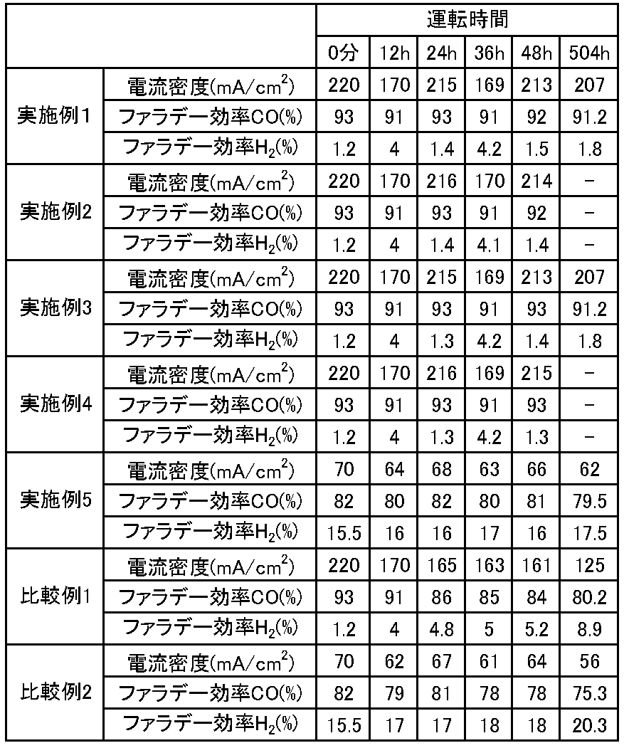
表1からわかるとおり、リフレッシュ動作を行うことにより、電流密度、COのファラデー効率、およびH2のファラデー効率の少なくとも一つを改善させることができることがわかる。このことは、従来よりも長時間にわたってセル性能を維持できることを示している。
なお、上述した各実施形態の構成は、それぞれ組合せて適用することができ、また一部置き換えることも可能である。ここでは、本発明のいくつかの実施形態を説明したが、これらの実施形態は例として提示したものであり、発明の範囲を限定することは意図するものではない。これら実施形態は、その他の様々な形態で実施し得るものであり、発明の要旨を逸脱しない範囲において、種々の省略、置き換え、変更等を行うことができる。これら実施形態やその変形は、発明の範囲や要旨に含まれると同時に、特許請求の範囲に記載された発明とその均等の範囲に含まれるものである。
Claims (15)
- 二酸化炭素を還元して炭素化合物を生成するための第1の触媒を含む第1の電極と、水または水酸化物イオンを酸化して酸素を生成するための第2の触媒を含む第2の電極と、前記第1の電極に面する第1の電極流路と、前記第2の電極に面する第2の電極流路と、前記第1の電極と前記第2の電極とを分離するセパレータと、を備える電解セルと、
前記第1の電極と前記第2の電極との間に電圧を印加する電源制御部と、
前記二酸化炭素が流れる第1の流路と、
前記炭素化合物が流れる第2の流路と、
前記水を含む電解溶液が流れる第3の流路と、
前記酸素が流れる第4の流路と、
前記第1の電極流路と前記第1の流路とを接続するための第1のバルブと、
前記第1の電極流路と前記第2の流路とを接続するための第2のバルブと、
前記第1の電極流路に接続され、リンス液を収容するためのタンクと、
前記電解セルの性能の要求基準に基づいて前記第1のバルブおよび前記第2のバルブの開閉を制御する制御部と、を具備する、二酸化炭素電解装置。 - 前記第2の電極流路と前記第3の流路とを接続するための第3のバルブと、
前記第2の電極流路と前記第4の流路とを接続するための第4のバルブと、
二酸化炭素が流れる第5の流路と、
前記第2の電極流路と前記第5の流路とを接続するための第5のバルブと、
をさらに具備し、
前記制御部は、前記要求基準に基づいて前記第3のバルブないし前記第5のバルブの開閉をさらに制御する、請求項1に記載の二酸化炭素電解装置。 - 前記第2の電極流路と前記第3の流路とを接続するための第3のバルブと、
前記第2の電極流路と前記第4の流路とを接続するための第4のバルブと、
酸素が流れる第5の流路と、
前記第1の電極流路または前記第2の電極流路と前記第5の流路とを接続するための第5のバルブと、
をさらに具備し、
前記制御部は、前記要求基準に基づいて前記第3のバルブないし前記第5のバルブの開閉をさらに制御する、請求項1に記載の二酸化炭素電解装置。 - 前記リンス液は、酸性リンス液および前記水からなる群より選ばれる少なくとも一つを含む、請求項1に記載の二酸化炭素電解装置。
- 前記制御部により制御され、露出された前記第1の電極流路および前記第2の電極流路の少なくとも一方にガス状物質を供給するガス供給部をさらに具備する、請求項1に記載の二酸化炭素電解装置。
- 前記制御部により制御され、前記ガス状物質の流量を調整する流量制御部をさらに具備する、請求項5に記載の二酸化炭素電解装置。
- 前記ガス状物質は、空気、二酸化炭素、酸素、窒素、およびアルゴンからなる群より選ばれる少なくとも1つを含む、請求項5に記載の二酸化炭素電解装置。
- 前記電解セルは、前記第1の電極が浸漬される第2の電解溶液を収容するための第1の溶液槽と、前記第2の電極が浸漬される前記電解溶液を収容するための第2の溶液槽と、をさらに備える、請求項1に記載の二酸化炭素電解装置。
- 前記第1の電極および前記第2の電極のそれぞれは、前記セパレータと接している、請求項1に記載の二酸化炭素電解装置。
- 前記電解セルは、前記第1の電極と前記セパレータとの間に設けられ、前記電解溶液または第2の電解溶液が流れる第3の電極流路をさらに備える、請求項1に記載の二酸化炭素電解装置。
- 前記性能は、前記電解セルのセル電圧、セル電流、および前記炭素化合物のファラデー効率の少なくとも一つを含むパラメータにより定義される、請求項1に記載の二酸化炭素電解装置。
- 二酸化炭素を還元して炭素化合物を生成するための第1の触媒を含む第1の電極に面する第1の電極流路と前記二酸化炭素が流れる第1の流路とを接続するための第1のバルブと、前記第1の電極流路と前記炭素化合物が流れる第2の流路とを接続するための第2のバルブと、を開けることにより、前記第1の流路から第1の電極流路に前記二酸化炭素を供給すると共に、水または水酸化物イオンを酸化して酸素を生成するための第2の触媒を含む第2の電極に面する第2の電極流路に水を含む電解溶液を供給するステップと、
前記第1の電極と前記第2の電極との間に電圧を印加し、前記第1の電極付近で前記二酸化炭素を還元して前記炭素化合物を生成すると共に、前記第2の電極付近で前記水または水酸化物イオンを酸化して前記酸素を生成するステップと、
前記第1の電極と、前記第2の電極と、前記第1の電極流路と、前記第2の電極流路と、前記第1の電極と前記第2の電極とを分離するセパレータと、を具備する電解セルの性能の要求基準に基づいて前記第1の電極流路に接続されたタンクに収容されるリンス液の少なくとも一部を前記第1の電極流路に供給するために、前記第1のバルブと前記第2のバルブとを閉じて前記第1の電極流路の内部に残存する前記二酸化炭素の少なくとも一部を前記リンス液に吸収させることにより前記第1の電極流路の内部を減圧するステップと、
を具備する二酸化炭素電解方法。 - 二酸化炭素を還元して炭素化合物を生成するための第1の触媒を含む第1の電極に面する第1の電極流路と前記二酸化炭素が流れる第1の流路とを接続するための第1のバルブと、前記第1の電極流路と前記炭素化合物が流れる第2の流路とを接続するための第2のバルブと、を開けて前記第1の流路から第1の電極流路に前記二酸化炭素を供給し、水または水酸化物イオンを酸化して酸素を生成するための第2の触媒を含む第2の電極に面する第2の電極流路と前記水を含む電解溶液が流れる第3の流路とを接続するための第3のバルブと、前記第2の電極流路と前記酸素が流れる第4の流路とを接続するための第4のバルブと、を開けて前記第3の流路から前記第2の電極流路に水を含む電解溶液を供給し、前記第2の電極流路と二酸化炭素が流れる第5の流路とを接続するための第5のバルブを閉じるステップと、
前記第1の電極と前記第2の電極との間に電圧を印加し、前記第1の電極付近で前記二酸化炭素を還元して前記炭素化合物を生成すると共に、前記第2の電極付近で前記水または水酸化物イオンを酸化して前記酸素を生成するステップと、
前記第1の電極と、前記第2の電極と、前記第1の電極流路と、前記第2の電極流路と、前記第1の電極と前記第2の電極とを分離するセパレータと、を具備する電解セルの性能の要求基準に基づいて前記第1の電極流路に接続されたタンクに収容されるリンス液の少なくとも一部を前記第1の電極流路および前記第2の電極流路に供給するために、前記第1のバルブと前記第2のバルブと前記第5のバルブとを閉じ、前記第3のバルブを閉じると共に前記第5のバルブを開けて前記第5の流路から前記第2の電極流路に前記二酸化炭素を供給し、前記第4のバルブと前記第5のバルブとを閉じて残存する前記二酸化炭素の少なくとも一部を前記第1の電極流路に接続されたタンクに収容されるリンス液に吸収させることにより前記第1の電極流路の内部および前記第2の電極流路の内部を減圧するステップと、
を具備する、二酸化炭素電解方法。 - 二酸化炭素を還元して炭素化合物を生成し、酸素を還元して水を生成し、水または水酸化物イオンを酸化して酸素を生成するための第1の触媒を含む第1の電極に面する第1の電極流路と前記二酸化炭素が流れる第1の流路とを接続する第1のバルブと、前記第1の電極流路と前記炭素化合物が流れる第2の流路とを接続する第2のバルブと、を開けて前記第1の流路から前記第1の電極流路に前記二酸化炭素を供給すると共に、水または水酸化物イオンを酸化して酸素を生成し、酸素を還元して水を生成するための第2の触媒を含む第2の電極に面する第2の電極流路と前記水を含む電解溶液が流れる第3の流路とを接続する第3のバルブと、前記第2の電極流路と前記酸素が流れる第4の流路とを接続する第4のバルブと、を開けて前記第3の流路から前記第2の電極流路に前記電解溶液を供給し、前記第1の電極流路または前記第2の電極流路と前記酸素が流れる第5の流路とを接続するための第5のバルブを閉じるステップと、
前記第1の電極と前記第2の電極との間に第1の電圧を印加し、前記第1の電極付近で前記二酸化炭素を還元して前記炭素化合物を生成すると共に、前記第2の電極付近で前記水または水酸化物イオンを酸化して前記酸素を生成するステップと、
前記第1の電極と、前記第2の電極と、前記第1の電極流路と、前記第2の電極流路と、前記第1の電極と前記第2の電極とを分離するセパレータと、を具備する電解セルの性能の要求基準に基づいて水を含むリンス液を前記第1の電極流路、前記第2の電極流路、および前記第1の電極流路に接続されたタンクに供給するために、前記第1のバルブを閉じ、前記第2のバルブを閉じると共に前記第5のバルブを開けて前記第1の電極流路と前記第5の流路とを接続して前記酸素を前記第1の電極流路に供給し、前記第3のバルブと前記第5のバルブとを閉じると共に前記第1の電極と前記第2の電極との間に第2の電圧を印加して前記第1の電極付近で前記酸素を還元して前記水を生成すると共に前記第2の電極付近で前記水または水酸化物イオンを酸化して前記酸素を生成し、前記第2の電圧の印加を停止すると共に前記第5のバルブを開けて前記第2の電極流路と前記第5の流路とを接続して前記第2の電極流路に前記酸素を供給し、前記第5のバルブを閉じて前記第2のバルブを開けると共に前記第1の電極と前記第2の電極との間に第3の電圧を印加して前記第1の電極付近で前記水を酸化して酸素を生成すると共に前記第2の電極付近で前記酸素を還元して前記水を生成する、ステップと、
を具備する、二酸化炭素電解方法。 - 前記性能は、前記電解セルのセル電圧、セル電流、および前記炭素化合物のファラデー効率の少なくとも一つを含むパラメータにより定義される、請求項12に記載の二酸化炭素電解方法。
Priority Applications (1)
| Application Number | Priority Date | Filing Date | Title |
|---|---|---|---|
| US16/559,905 US11286573B2 (en) | 2018-03-22 | 2019-09-04 | Carbon dioxide electrolytic device and method of electrolyzing carbon dioxide |
Applications Claiming Priority (2)
| Application Number | Priority Date | Filing Date | Title |
|---|---|---|---|
| JP2018054093A JP6818711B2 (ja) | 2018-03-22 | 2018-03-22 | 二酸化炭素電解装置および二酸化炭素電解方法 |
| JP2018-054093 | 2018-03-22 |
Related Child Applications (1)
| Application Number | Title | Priority Date | Filing Date |
|---|---|---|---|
| US16/559,905 Continuation US11286573B2 (en) | 2018-03-22 | 2019-09-04 | Carbon dioxide electrolytic device and method of electrolyzing carbon dioxide |
Publications (1)
| Publication Number | Publication Date |
|---|---|
| WO2019181002A1 true WO2019181002A1 (ja) | 2019-09-26 |
Family
ID=67986880
Family Applications (1)
| Application Number | Title | Priority Date | Filing Date |
|---|---|---|---|
| PCT/JP2018/033690 Ceased WO2019181002A1 (ja) | 2018-03-22 | 2018-09-11 | 二酸化炭素電解装置および二酸化炭素電解方法 |
Country Status (3)
| Country | Link |
|---|---|
| US (1) | US11286573B2 (ja) |
| JP (1) | JP6818711B2 (ja) |
| WO (1) | WO2019181002A1 (ja) |
Cited By (2)
| Publication number | Priority date | Publication date | Assignee | Title |
|---|---|---|---|---|
| EP3626859B1 (en) * | 2018-09-19 | 2022-08-10 | Kabushiki Kaisha Toshiba | Electrochemical reaction device |
| JP2022141239A (ja) * | 2021-03-15 | 2022-09-29 | 株式会社東芝 | 二酸化炭素電解装置及び二酸化炭素電解方法 |
Families Citing this family (21)
| Publication number | Priority date | Publication date | Assignee | Title |
|---|---|---|---|---|
| WO2020132064A1 (en) | 2018-12-18 | 2020-06-25 | Opus 12 Inc. | Electrolyzer and method of use |
| JP2021008655A (ja) * | 2019-07-02 | 2021-01-28 | 株式会社デンソー | エネルギ変換システム |
| JP7242601B2 (ja) * | 2020-03-23 | 2023-03-20 | 株式会社東芝 | 二酸化炭素電解装置 |
| CN115298361B (zh) * | 2020-03-31 | 2025-11-18 | 大阪瓦斯株式会社 | 电解池单元、电解池装置及烃制备系统、电解池单元的制备方法及使用方法 |
| DE102020206341A1 (de) * | 2020-05-20 | 2021-11-25 | Siemens Aktiengesellschaft | Korrosionsschutz in einem CO2-Elektrolyse-Stack |
| CN116096477A (zh) * | 2020-07-14 | 2023-05-09 | 伊利诺伊大学评议会 | 用于碳捕获和转化的系统和工艺 |
| JP7247150B2 (ja) * | 2020-09-02 | 2023-03-28 | 株式会社東芝 | 二酸化炭素電解装置および二酸化炭素電解方法 |
| JP7316309B2 (ja) | 2021-02-26 | 2023-07-27 | 本田技研工業株式会社 | 二酸化炭素処理装置、二酸化炭素処理方法及び炭素化合物の製造方法 |
| JP7203875B2 (ja) * | 2021-03-04 | 2023-01-13 | 本田技研工業株式会社 | 電気化学反応装置、二酸化炭素の還元方法、及び炭素化合物の製造方法 |
| JP7203876B2 (ja) * | 2021-03-04 | 2023-01-13 | 本田技研工業株式会社 | 電気化学反応装置、二酸化炭素の還元方法、及び炭素化合物の製造方法 |
| JP7542467B2 (ja) * | 2021-03-18 | 2024-08-30 | 株式会社東芝 | 二酸化炭素電解装置および二酸化炭素電解装置の運転方法 |
| JP7520757B2 (ja) * | 2021-03-18 | 2024-07-23 | 株式会社東芝 | 二酸化炭素電解装置 |
| DE102021205987A1 (de) * | 2021-06-14 | 2022-12-15 | Robert Bosch Gesellschaft mit beschränkter Haftung | Verfahren zur Regenerierung einer elektrochemischen Zelleneinheit |
| JP7316339B2 (ja) | 2021-10-18 | 2023-07-27 | 本田技研工業株式会社 | 二酸化炭素処理装置、二酸化炭素処理方法及び炭素化合物の製造方法 |
| US20230407495A1 (en) * | 2022-06-14 | 2023-12-21 | Giner, Inc. | Gas diffusion electrode suitable for use in carbon dioxide electrolyzer and membrane electrode assembly including said gas diffusion electrode |
| JP7797344B2 (ja) * | 2022-09-15 | 2026-01-13 | 株式会社東芝 | 電解装置 |
| JP7775169B2 (ja) * | 2022-09-15 | 2025-11-25 | 株式会社東芝 | 電解装置および電解装置の制御方法 |
| JP7830292B2 (ja) * | 2022-11-04 | 2026-03-16 | 東芝エネルギーシステムズ株式会社 | 電気分解装置 |
| WO2024258243A1 (ko) * | 2023-06-16 | 2024-12-19 | 주식회사 엘지화학 | 전기분해 장치 |
| KR20240176639A (ko) * | 2023-06-16 | 2024-12-24 | 주식회사 엘지화학 | 전기분해 장치 |
| WO2026009268A1 (ja) * | 2024-07-01 | 2026-01-08 | Ntt株式会社 | 二酸化炭素還元システム |
Citations (5)
| Publication number | Priority date | Publication date | Assignee | Title |
|---|---|---|---|---|
| WO2011135783A1 (ja) * | 2010-04-26 | 2011-11-03 | パナソニック株式会社 | 二酸化炭素を還元する方法 |
| JP2013536319A (ja) * | 2010-07-29 | 2013-09-19 | リキッド・ライト・インコーポレーテッド | 二酸化炭素の生成物への還元 |
| WO2015178019A1 (ja) * | 2014-05-20 | 2015-11-26 | 株式会社 東芝 | 光電気化学反応装置 |
| JP2017172037A (ja) * | 2016-03-18 | 2017-09-28 | 株式会社東芝 | 電気化学反応装置 |
| JP2018034136A (ja) * | 2016-09-02 | 2018-03-08 | 株式会社東芝 | Co2還元触媒、co2還元電極およびco2還元装置 |
Family Cites Families (6)
| Publication number | Priority date | Publication date | Assignee | Title |
|---|---|---|---|---|
| US9145615B2 (en) * | 2010-09-24 | 2015-09-29 | Yumei Zhai | Method and apparatus for the electrochemical reduction of carbon dioxide |
| JP5624860B2 (ja) | 2010-11-25 | 2014-11-12 | 古河電気工業株式会社 | 電解セル、電解装置、炭化水素の生成方法 |
| FR2981369B1 (fr) | 2011-10-12 | 2013-11-15 | Areva | Procede et systeme de traitement de gaz carbones par hydrogenation electrochimique pour l'obtention d'un compose de type cxhyoz |
| JP6622237B2 (ja) | 2017-03-14 | 2019-12-18 | 株式会社東芝 | 二酸化炭素電解装置 |
| JP6649307B2 (ja) * | 2017-03-21 | 2020-02-19 | 株式会社東芝 | 電気化学反応装置 |
| JP6672211B2 (ja) | 2017-03-21 | 2020-03-25 | 株式会社東芝 | 二酸化炭素電解装置および二酸化炭素電解方法 |
-
2018
- 2018-03-22 JP JP2018054093A patent/JP6818711B2/ja active Active
- 2018-09-11 WO PCT/JP2018/033690 patent/WO2019181002A1/ja not_active Ceased
-
2019
- 2019-09-04 US US16/559,905 patent/US11286573B2/en active Active
Patent Citations (5)
| Publication number | Priority date | Publication date | Assignee | Title |
|---|---|---|---|---|
| WO2011135783A1 (ja) * | 2010-04-26 | 2011-11-03 | パナソニック株式会社 | 二酸化炭素を還元する方法 |
| JP2013536319A (ja) * | 2010-07-29 | 2013-09-19 | リキッド・ライト・インコーポレーテッド | 二酸化炭素の生成物への還元 |
| WO2015178019A1 (ja) * | 2014-05-20 | 2015-11-26 | 株式会社 東芝 | 光電気化学反応装置 |
| JP2017172037A (ja) * | 2016-03-18 | 2017-09-28 | 株式会社東芝 | 電気化学反応装置 |
| JP2018034136A (ja) * | 2016-09-02 | 2018-03-08 | 株式会社東芝 | Co2還元触媒、co2還元電極およびco2還元装置 |
Cited By (4)
| Publication number | Priority date | Publication date | Assignee | Title |
|---|---|---|---|---|
| EP3626859B1 (en) * | 2018-09-19 | 2022-08-10 | Kabushiki Kaisha Toshiba | Electrochemical reaction device |
| US11946150B2 (en) | 2018-09-19 | 2024-04-02 | Kabushiki Kaisha Toshiba | Electrochemical reaction device |
| JP2022141239A (ja) * | 2021-03-15 | 2022-09-29 | 株式会社東芝 | 二酸化炭素電解装置及び二酸化炭素電解方法 |
| JP7520754B2 (ja) | 2021-03-15 | 2024-07-23 | 株式会社東芝 | 二酸化炭素電解装置及び二酸化炭素電解方法 |
Also Published As
| Publication number | Publication date |
|---|---|
| JP6818711B2 (ja) | 2021-01-20 |
| US11286573B2 (en) | 2022-03-29 |
| JP2019167556A (ja) | 2019-10-03 |
| US20200002821A1 (en) | 2020-01-02 |
Similar Documents
| Publication | Publication Date | Title |
|---|---|---|
| JP6818711B2 (ja) | 二酸化炭素電解装置および二酸化炭素電解方法 | |
| JP6845114B2 (ja) | 二酸化炭素電解装置および二酸化炭素電解方法 | |
| JP6622237B2 (ja) | 二酸化炭素電解装置 | |
| JP6783814B2 (ja) | 二酸化炭素電解装置および二酸化炭素電解方法 | |
| JP6672211B2 (ja) | 二酸化炭素電解装置および二酸化炭素電解方法 | |
| EP3626858B1 (en) | Carbon dioxide electrolytic device and method of electrolyzing carbon dioxide | |
| JP7242601B2 (ja) | 二酸化炭素電解装置 | |
| EP3623501B1 (en) | Carbon dioxide electrolytic device | |
| JP7204619B2 (ja) | 二酸化炭素電解装置及び二酸化炭素電解方法 | |
| JP2018123390A (ja) | 二酸化炭素の電解セルと電解装置 | |
| US12241170B2 (en) | Carbon dioxide electrolytic device | |
| WO2019176141A1 (ja) | 二酸化炭素の電解セルと電解装置 | |
| US12031219B2 (en) | Carbon dioxide electrolytic device and method of electrolyzing carbon dioxide |
Legal Events
| Date | Code | Title | Description |
|---|---|---|---|
| 121 | Ep: the epo has been informed by wipo that ep was designated in this application |
Ref document number: 18910855 Country of ref document: EP Kind code of ref document: A1 |
|
| NENP | Non-entry into the national phase |
Ref country code: DE |
|
| 122 | Ep: pct application non-entry in european phase |
Ref document number: 18910855 Country of ref document: EP Kind code of ref document: A1 |