WO2019181205A1 - Dispositif de traitement d'image, système de traitement d'informations et procédé de traitement d'informations - Google Patents
Dispositif de traitement d'image, système de traitement d'informations et procédé de traitement d'informations Download PDFInfo
- Publication number
- WO2019181205A1 WO2019181205A1 PCT/JP2019/002718 JP2019002718W WO2019181205A1 WO 2019181205 A1 WO2019181205 A1 WO 2019181205A1 JP 2019002718 W JP2019002718 W JP 2019002718W WO 2019181205 A1 WO2019181205 A1 WO 2019181205A1
- Authority
- WO
- WIPO (PCT)
- Prior art keywords
- fluorescence
- information processing
- sample
- light irradiation
- intensity
- Prior art date
- Legal status (The legal status is an assumption and is not a legal conclusion. Google has not performed a legal analysis and makes no representation as to the accuracy of the status listed.)
- Ceased
Links
Images


Classifications
-
- G—PHYSICS
- G01—MEASURING; TESTING
- G01N—INVESTIGATING OR ANALYSING MATERIALS BY DETERMINING THEIR CHEMICAL OR PHYSICAL PROPERTIES
- G01N15/00—Investigating characteristics of particles; Investigating permeability, pore-volume or surface-area of porous materials
- G01N15/10—Investigating individual particles
- G01N15/14—Optical investigation techniques, e.g. flow cytometry
- G01N15/1456—Optical investigation techniques, e.g. flow cytometry without spatial resolution of the texture or inner structure of the particle, e.g. processing of pulse signals
- G01N15/1459—Optical investigation techniques, e.g. flow cytometry without spatial resolution of the texture or inner structure of the particle, e.g. processing of pulse signals the analysis being performed on a sample stream
-
- G—PHYSICS
- G01—MEASURING; TESTING
- G01N—INVESTIGATING OR ANALYSING MATERIALS BY DETERMINING THEIR CHEMICAL OR PHYSICAL PROPERTIES
- G01N15/00—Investigating characteristics of particles; Investigating permeability, pore-volume or surface-area of porous materials
- G01N15/10—Investigating individual particles
- G01N15/1012—Calibrating particle analysers; References therefor
-
- G—PHYSICS
- G01—MEASURING; TESTING
- G01N—INVESTIGATING OR ANALYSING MATERIALS BY DETERMINING THEIR CHEMICAL OR PHYSICAL PROPERTIES
- G01N15/00—Investigating characteristics of particles; Investigating permeability, pore-volume or surface-area of porous materials
- G01N15/10—Investigating individual particles
- G01N15/14—Optical investigation techniques, e.g. flow cytometry
- G01N15/1429—Signal processing
-
- G—PHYSICS
- G01—MEASURING; TESTING
- G01N—INVESTIGATING OR ANALYSING MATERIALS BY DETERMINING THEIR CHEMICAL OR PHYSICAL PROPERTIES
- G01N15/00—Investigating characteristics of particles; Investigating permeability, pore-volume or surface-area of porous materials
- G01N15/10—Investigating individual particles
- G01N15/14—Optical investigation techniques, e.g. flow cytometry
- G01N15/149—Optical investigation techniques, e.g. flow cytometry specially adapted for sorting particles, e.g. by their size or optical properties
- G01N15/1492—Optical investigation techniques, e.g. flow cytometry specially adapted for sorting particles, e.g. by their size or optical properties within droplets
-
- G—PHYSICS
- G01—MEASURING; TESTING
- G01N—INVESTIGATING OR ANALYSING MATERIALS BY DETERMINING THEIR CHEMICAL OR PHYSICAL PROPERTIES
- G01N21/00—Investigating or analysing materials by the use of optical means, i.e. using sub-millimetre waves, infrared, visible or ultraviolet light
- G01N21/17—Systems in which incident light is modified in accordance with the properties of the material investigated
- G01N21/47—Scattering, i.e. diffuse reflection
- G01N21/49—Scattering, i.e. diffuse reflection within a body or fluid
- G01N21/53—Scattering, i.e. diffuse reflection within a body or fluid within a flowing fluid, e.g. smoke
-
- G—PHYSICS
- G01—MEASURING; TESTING
- G01N—INVESTIGATING OR ANALYSING MATERIALS BY DETERMINING THEIR CHEMICAL OR PHYSICAL PROPERTIES
- G01N21/00—Investigating or analysing materials by the use of optical means, i.e. using sub-millimetre waves, infrared, visible or ultraviolet light
- G01N21/62—Systems in which the material investigated is excited whereby it emits light or causes a change in wavelength of the incident light
- G01N21/63—Systems in which the material investigated is excited whereby it emits light or causes a change in wavelength of the incident light optically excited
- G01N21/64—Fluorescence; Phosphorescence
- G01N21/6402—Atomic fluorescence; Laser induced fluorescence
-
- G—PHYSICS
- G01—MEASURING; TESTING
- G01N—INVESTIGATING OR ANALYSING MATERIALS BY DETERMINING THEIR CHEMICAL OR PHYSICAL PROPERTIES
- G01N21/00—Investigating or analysing materials by the use of optical means, i.e. using sub-millimetre waves, infrared, visible or ultraviolet light
- G01N21/62—Systems in which the material investigated is excited whereby it emits light or causes a change in wavelength of the incident light
- G01N21/63—Systems in which the material investigated is excited whereby it emits light or causes a change in wavelength of the incident light optically excited
- G01N21/64—Fluorescence; Phosphorescence
- G01N21/6486—Measuring fluorescence of biological material, e.g. DNA, RNA, cells
-
- G—PHYSICS
- G01—MEASURING; TESTING
- G01N—INVESTIGATING OR ANALYSING MATERIALS BY DETERMINING THEIR CHEMICAL OR PHYSICAL PROPERTIES
- G01N33/00—Investigating or analysing materials by specific methods not covered by groups G01N1/00 - G01N31/00
- G01N33/48—Biological material, e.g. blood, urine; Haemocytometers
- G01N33/50—Chemical analysis of biological material, e.g. blood, urine; Testing involving biospecific ligand binding methods; Immunological testing
- G01N33/58—Chemical analysis of biological material, e.g. blood, urine; Testing involving biospecific ligand binding methods; Immunological testing involving labelled substances
- G01N33/582—Chemical analysis of biological material, e.g. blood, urine; Testing involving biospecific ligand binding methods; Immunological testing involving labelled substances with fluorescent label
-
- G—PHYSICS
- G01—MEASURING; TESTING
- G01N—INVESTIGATING OR ANALYSING MATERIALS BY DETERMINING THEIR CHEMICAL OR PHYSICAL PROPERTIES
- G01N15/00—Investigating characteristics of particles; Investigating permeability, pore-volume or surface-area of porous materials
- G01N15/10—Investigating individual particles
- G01N15/14—Optical investigation techniques, e.g. flow cytometry
- G01N15/149—Optical investigation techniques, e.g. flow cytometry specially adapted for sorting particles, e.g. by their size or optical properties
-
- G—PHYSICS
- G01—MEASURING; TESTING
- G01N—INVESTIGATING OR ANALYSING MATERIALS BY DETERMINING THEIR CHEMICAL OR PHYSICAL PROPERTIES
- G01N15/00—Investigating characteristics of particles; Investigating permeability, pore-volume or surface-area of porous materials
- G01N15/10—Investigating individual particles
- G01N2015/1006—Investigating individual particles for cytology
Definitions
- This technology relates to an information processing apparatus that processes fluorescence information obtained from a fluorescently labeled sample. More specifically, the present invention relates to an information processing apparatus, an information processing system, and an information processing method that obtain information on the sensitivity of fluorescence detection based on fluorescence information obtained from a fluorescently labeled sample.
- microparticles such as cells and microorganisms
- microparticles such as microbeads
- a method for analyzing and sorting the fine particles is being developed.
- Flow cytometry is a method of detecting fluorescence and scattered light emitted from each microparticle by pouring the microparticles to be analyzed in a state of being aligned in the fluid and irradiating the microparticles with laser light, etc. This is an analysis method for analyzing and sorting fine particles.
- microparticles In the analysis of microparticles typified by flow cytometry, many optical methods are used to detect the fluorescence and scattered light emitted from the microparticles by irradiating the microparticles to be analyzed with light such as a laser. . Then, based on the detected optical information, a histogram is extracted by an analysis computer and software, and analysis is performed.
- quality control In the optical analysis of microparticles, quality control (QC: Quality ⁇ Control) is used to verify the accuracy, etc., and to confirm / standardize the operation of the microparticles before optical measurement of the actual microparticles. ) May be performed.
- QC Quality ⁇ Control
- this quality control when evaluating the performance of an apparatus, usually, a plurality of beads (3 peak beads, 6 peak beads, 8 peak beads, etc.) labeled with fluorescent dyes having different fluorescence intensities are used. .
- Patent Document 1 relates to a fluorescence-labeled test cell from a two-dimensional correlation diagram of the fluorescence-labeled test cell obtained by a flow cytometer.
- a program that calculates the centroid value of a fluorescent population and corrects the fluorescence value using the fluorescence value of a fluorescently labeled test cell corresponding to the centroid value and a predetermined determinant.
- one kind of beads align check beads, Ultra Rainbow fluorescent particles, etc. labeled with a fluorescent dye having a single fluorescence intensity, which usually gives a wide spectrum. Etc. are used.
- beads suitable for device performance evaluation and beads suitable for device adjustment are different from each other. Therefore, beads for device performance evaluation and devices for device adjustment are different. It was necessary to prepare two types of beads.
- beads composed of a plurality of types labeled with fluorescent dyes having different fluorescence intensities such as 3-peak beads, 6-peak beads, and 8-peak beads suitable for performance evaluation of the apparatus, have a narrow excitation wavelength region and fluorescence wavelength region,
- the intensity of the obtained fluorescence is generally low, and particularly when it is 700 nm or less, the obtained intensity is extremely lowered.
- the main object of the present technology is to provide a technology capable of performing device performance evaluation and device adjustment in optical analysis of fine particles with high accuracy using the same beads.
- the inventors of the present invention have conducted extensive research to solve the above-mentioned object, and as a result, paying attention to the setting of the light irradiation power, a wide range that has been used when adjusting the apparatus in conventional quality control.
- a single type of bead labeled with a fluorescent dye having a single fluorescence intensity that yields the spectrum of the above the performance of the apparatus was successfully evaluated with high accuracy, and the present technology was completed.
- a fluorescence signal from a sample made of particles labeled with a fluorescent dye having a single fluorescence intensity a plurality of fluorescence intensities at a plurality of light irradiation powers are acquired, and the fluorescence intensity of the sample is acquired.
- an information processing apparatus including an information processing unit that recognizes an intensity range for each of a plurality of fluorescence intensities detected based on a ratio and calculates information on sensitivity of a fluorescence detection unit.
- the light irradiation power may be at least 3 or at least 5 different powers.
- the information processing unit can recognize the fluorescence intensity range obtained from the sheath liquid not including the sample as the minimum intensity range, and can calculate information on the sensitivity of the fluorescence detection unit.
- Information on the sensitivity of the fluorescence detection unit that can be calculated by the information processing apparatus according to the present technology includes linearity and / or fluorescence detection sensitivity based on the fluorescence intensity and the number of particles.
- a trigger can be applied with a constant light irradiation power by an excitation laser different from an excitation laser for acquiring a plurality of fluorescence intensities at a plurality of light irradiation powers.
- the information processing unit can also calculate information related to the adjustment of the fluorescence detection unit based on a fluorescence signal from a sample made of particles labeled with the fluorescent dye having the single fluorescence intensity. .
- an irradiation unit that irradiates light to a sample composed of particles labeled with a fluorescent dye having a single fluorescence intensity; and A detection unit for detecting a fluorescence signal from the sample; For the fluorescence signal, a plurality of fluorescence intensities at a plurality of light irradiation powers are acquired, an intensity range for each of a plurality of fluorescence intensities detected based on a fluorescence intensity ratio of the sample is recognized, and information on sensitivity of the detection unit An information processing unit for calculating An information processing system is provided.
- a fluorescence signal from a sample made of particles labeled with a fluorescent dye having a single fluorescence intensity a plurality of fluorescence intensities at a plurality of light irradiation powers are acquired, and the fluorescence intensity ratio of the sample is obtained.
- device performance evaluation and device adjustment in optical analysis of fine particles can be performed with high accuracy using the same beads.
- the effect described here is not necessarily limited, and may be any effect described in the present technology.
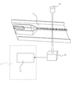
- FIG. 2 is a schematic conceptual diagram schematically showing an example of a flow cytometer that can use the information processing apparatus 1 according to the present technology.
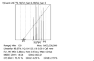
- It is a drawing substitute graph which shows an example of the result of recognizing each intensity range in eight kinds of light irradiation powers in the fluorescence region of Brilliant Violet (BV421) using Ultra Rainbow fluorescent particles.
- It is a drawing substitute graph which shows an example of the result of having recognized each intensity range in eight kinds of light irradiation powers in the fluorescence field of Phycoerythrin (PE) using Ultra * Rainbow fluorescent particles.
- PE Phycoerythrin
- It is a drawing substitute graph which shows an example of the regression line A in the case of performing performance evaluation of an apparatus using 8 types of light irradiation power.
- Information processing device 1 (1) Information processing unit 11 2. Information processing system 10 (1) Information processing unit 11 (2) Light irradiation unit 12 (3) Fluorescence detection unit 13 (4) Sorting unit 14 3. Information processing method
- the information processing apparatus 1 according to the present technology is an information processing apparatus that can be used when performing optical analysis of fine particles, and includes at least an information processing unit 11.
- An example of an apparatus that performs optical analysis of fine particles that can use the information processing apparatus 1 according to the present technology is a flow cytometer.
- FIG. 1 is a schematic conceptual diagram schematically showing an example of a flow cytometer that can use the information processing apparatus 1 according to the present technology.
- analysis of microparticles is performed by detecting optical information obtained from microparticles arranged in a line in a flow cell (flow path P). And can be sorted.
- the flow path P may be provided in advance in the flow cytometer, but a commercially available flow path P or a disposable chip provided with the flow path P may be installed in the flow cytometer for analysis or sorting. Is possible.
- the form of the flow path P is not particularly limited, and can be freely designed.
- it is not limited to the flow path P formed in the two-dimensional or three-dimensional plastic or glass substrate T as shown in FIG. 1, but is used in a conventional flow cytometer as shown in FIG.
- Such a flow path P can also be used for a flow cytometer.
- the channel width, the channel depth, and the channel cross-sectional shape of the channel P are not particularly limited as long as they can form a laminar flow, and can be freely designed.
- a microchannel having a channel width of 1 mm or less can also be used for the flow cytometer.
- a micro flow channel having a flow channel width of 10 ⁇ m or more and 1 mm or less can be suitably used by a flow cytometer capable of using the information processing apparatus 1 according to the present technology.
- Information processing unit 11 calculates information related to the sensitivity of the fluorescence detection unit (hereinafter also referred to as “sensitivity information”). The calculation of sensitivity information is performed according to the following procedure.
- a plurality of fluorescence intensities at a plurality of light irradiation powers are acquired for a fluorescence signal from a sample composed of particles labeled with a fluorescent dye having a single fluorescence intensity.
- the fluorescence signal is obtained by converting optical information detected by a fluorescence detection unit 12 of a flow cytometer described later into an electrical signal (voltage pulse), and converting the converted electrical signal into an analog-digital signal. Can be used.
- Examples of the sample made of particles labeled with a fluorescent dye having a single fluorescence intensity include alignment check beads, Ultra-Rainbow fluorescent particles, and the like.
- a sample containing particles labeled with one type of fluorescent dye can be used.
- fluorescent dyes that can be used in this technology include Cascade Blue, Pacific Blue, Fluorescein Isothiocyanate (FITC), Phycoerythrin (PE), Propidium Iodide (PI), Texas Red (TR), Peridinin chlorophyll protein (PerCP ), Allophycocyanin (APC), 4 ′, 6-Diamidino-2-phenylindole (DAPI), Cy3, Cy5, Cy7, Brilliant Violet (BV421), and the like.
- the plurality of light irradiation powers it is preferable to use 3 or more different powers, more preferably 5 or more different powers, and still more preferably 8 or more different powers.
- the linearity by the fluorescence intensity and the number of particles and the fluorescence detection sensitivity (MESF: Molecules ⁇ Equivalent Soluble Fluorochromes) can be obtained as information on the sensitivity of the fluorescence detector.
- the Q value and the B value can be further obtained, and the performance evaluation of the apparatus can be performed with higher accuracy.
- FIGS. 2 is a result obtained from a sample using Brilliant Violet (BV421) as an example of a fluorescent dye
- FIG. 3 is a result obtained from a sample using Phycoerythrin (PE) as an example of a fluorescent dye. It is.
- the horizontal axis represents fluorescence intensity
- the vertical axis represents the number of particles (the same applies hereinafter).
- the fluorescence obtained from the sample consisting of particles labeled with a fluorescent dye having a single fluorescence intensity is adjusted to a desired level, and the light irradiation power is fixed at that value.
- the data of the maximum peak of a specific number of events is acquired (see symbol P8 in FIGS. 2 and 3).
- the light irradiation power is changed, and data of six peaks at a desired level is acquired (see symbols P2 to P7 in FIGS. 2 and 3).
- the median value (Median value) of the width (width) of the obtained seven peak data is determined, and the light irradiation power is set to the power at the time of measurement.
- the data of only the sheath liquid that does not include the above data is acquired at intervals of the median value (Median value) of the obtained Width (width) (see symbol P1 in FIGS. 2 and 3). According to such a procedure, the eight types of intensity ranges obtained from the sample are recognized while changing the light irradiation power.
- each intensity range is recognized in a plurality of states in advance. Therefore, it is not necessary to separate each intensity group. Further, as described above, the separation of the fluorescence intensity groups requires a high level of technology, and there is a problem that misidentification of each group occurs. However, in the present technology, such misperception cannot occur. As a result, the performance evaluation of the apparatus can be performed more easily and with high accuracy.
- the background signal of the apparatus is emitted with the light irradiation power emitted at the power at the time of measurement.
- the state of the device itself can be evaluated.
- optical noise and electrical noise are often dominant with respect to the background, and the optical noise includes autofluorescent components from the sheath liquid. If these are large, the fluorescence detection sensitivity (MESF) increases. .
- the excitation laser used for the channel to be evaluated is different from the excitation laser for the channel to be triggered. This is because a trigger different from the excitation laser for acquiring a plurality of fluorescence intensities at a plurality of light irradiation powers is used to stably trigger at a constant light irradiation power.
- a trigger different from the excitation laser for acquiring a plurality of fluorescence intensities at a plurality of light irradiation powers is used to stably trigger at a constant light irradiation power.
- the coaxial it is preferable to select a channel having a large level difference between lasers and a large output on the triggering side.
- Information relating to the sensitivity of the fluorescence detection unit is calculated based on the intensity ranges for each of the plurality of fluorescence intensities recognized above.
- Information on the sensitivity of the fluorescence detection unit that can be calculated by the information processing apparatus 1 according to the present technology includes linearity by fluorescence intensity and the number of particles, fluorescence detection sensitivity (MESF), Q value , B value and the like.
- EMF fluorescence detection sensitivity
- Linearity R (correlation coefficient) is obtained using LogMFI2 to LogMFI8 and LogME2 to LogME8, and is used as linearity. The linearity is better as it is closer to 100%.
- C Fluorescence detection sensitivity
- EMF Molecules of Equivalent Soluble Fluorochromes
- a regression line A is obtained using LogMFI2 to LogMFI8 and LogME2 to LogME8, and the slope of the straight line is a and the intercept is b.
- FIG. 4 shows an example of a regression line A in the case where the performance evaluation of the apparatus is performed using eight types of light irradiation power.
- the fluorescence detection sensitivity (MESF) is obtained using the following mathematical formula (1).
- the performance of the device is evaluated using a single type of sample labeled with a fluorescent dye having a single fluorescence intensity, which has been conventionally used for device adjustment. It is also possible to adjust the apparatus using the same sample. That is, in the present technology, the information processing unit also calculates information on adjustment of the fluorescence detection unit based on a fluorescence signal from a sample made of particles labeled with the fluorescent dye having a single fluorescence intensity. Can do.
- 1 type (s) or 2 or more types can be freely selected and used for a well-known method.
- the information processing system 10 is an information processing system that can be used when performing optical analysis of fine particles, and includes at least an information processing unit 11, a light irradiation unit 12, and a fluorescence detection unit 13. Moreover, it is also possible to provide the fractionation part 14 grade
- An example of an apparatus that performs optical analysis of fine particles that can use the information processing system 10 according to the present technology is a flow cytometer.
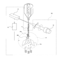
- FIG. 6 is a schematic conceptual diagram schematically illustrating an example of a flow cytometer that can use the information processing system 10 according to the present technology.
- the information processing unit 11 acquires a plurality of fluorescence intensities at a plurality of light irradiation powers based on a fluorescence signal acquired by a fluorescence detection unit described later, and each of the plurality of fluorescence intensities detected based on the fluorescence intensity ratio of the sample. Is recognized, and information related to the sensitivity of the detection unit is calculated. The details are the same as those of the information processing unit 11 of the information processing apparatus 1 described above, and thus description thereof is omitted here.
- Light irradiation unit 12 In the light irradiation unit 12, light is irradiated to a sample composed of a plurality of particles labeled with fluorescent dyes having different fluorescence intensities. Although the kind of light irradiated from the light irradiation part 12 is not specifically limited, In order to generate
- the type of the laser is not particularly limited, and an argon ion (Ar) laser, a helium-neon (He-Ne) laser, a die (dye) laser, a krypton (Cr) laser, a semiconductor laser, or a semiconductor laser
- Ar argon ion
- He-Ne helium-neon
- Dye die
- Ce krypton
- semiconductor laser or a semiconductor laser
- One or two or more solid lasers combined with wavelength conversion optical elements can be used in any combination.
- Fluorescence detection unit 13 detects a fluorescence signal from the sample.
- the type of the fluorescence detection unit 13 that can be used in the present technology is not particularly limited as long as the fluorescence signal from the sample can be detected, and a known photodetector can be freely selected and employed.
- fluorescence measuring instrument for example, fluorescence measuring instrument, scattered light measuring instrument, transmitted light measuring instrument, reflected light measuring instrument, diffracted light measuring instrument, ultraviolet spectroscopic measuring instrument, infrared spectroscopic measuring instrument, Raman spectroscopic measuring instrument, FRET measuring instrument, FISH measuring instrument and others
- spectrum measuring instruments PMT arrays or photodiode arrays in which light receiving elements such as PMTs and photodiodes are arranged one-dimensionally, or a plurality of independent detection channels such as two-dimensional light receiving elements such as CCD or CMOS, etc. These can be used singly or in combination of two or more.
- the installation location of the fluorescence detection unit 13 in the information processing system 10 according to the present technology is not particularly limited as long as the fluorescence signal from the sample can be detected, and can be freely designed.
- the fluorescence detection unit 13 may be arranged on the same side as the light irradiation unit 12 or on the side of the 90-degree side with respect to the flow path P. It doesn't matter.
- Sorting unit 14 sorts particles based on the fluorescence signal detected by the fluorescence detection unit 13 or the analysis result of the particles analyzed by the information processing unit 11. For example, the sorting unit 14 can sort particles downstream of the flow path P based on the analysis results of the size, form, internal structure, and the like of the particles analyzed from the optical information.
- a vibration element 14a that vibrates at a predetermined frequency is used to apply vibration to the whole or a part of the flow path P, thereby discharging the flow path P. Droplets are generated from the outlet.
- the vibration element 14a to be used is not particularly limited, and a known element can be freely selected and used.
- a piezoelectric vibration element or the like can be given.
- the size of the droplet can be adjusted to generate a droplet containing a certain amount of the sample. it can.
- the generated droplet is charged with a positive or negative charge based on the analysis result of the analyzed particle size, shape, internal structure, etc. (see reference numeral 14b in FIG. 6). Then, the charged droplets are sorted by changing the path in a desired direction by the counter electrode 14c to which a voltage is applied.
- the information processing method according to the present technology is an information processing method that can be used when performing optical analysis of fine particles, and is a method that performs at least an information processing step.
- a specific information processing method performed in the information processing step is the same as the method performed by the information processing unit 11 of the information processing apparatus 1 described above.
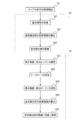
- FIG. 7 is a flowchart in the case where the performance of the apparatus is evaluated using eight types of light irradiation power.
- FIG. 7 is a flowchart showing a flow of information processing using the information processing method according to the present technology.
- sample particles First, a sample (for example, alignment check beads) made of particles labeled with a fluorescent dye having a single fluorescence intensity is started to flow into the flow path.
- a sample for example, alignment check beads
- a fluorescent dye having a single fluorescence intensity is started to flow into the flow path.
- the power of the excitation laser of the channel to be acquired is set to the value at the time of normal measurement, and the channel and the output level are set to the reference value in order to trigger with another laser.
- a sample for example, alignment check beads
- the fluorescence detection unit 13 for example, PMT (for example, a photomultiplier tube).
- HV voltage: High Voltage
- a set HV value may be applied every time. In this state, a certain number of events are acquired.
- the functions performed by the information processing unit 11 according to the present technology are hardware including a personal computer, a control unit including a CPU, a recording medium (nonvolatile memory (USB memory, etc.), HDD, CD, etc.), and the like. It can also be stored as a program in a hardware resource and functioned by a personal computer or a control unit.
- Example described below shows an example of a typical example of the present technology, and the scope of the present technology is not interpreted narrowly.
- “SP6800” manufactured by Sony Corporation was used.
- Example 1 In Experimental Example 1, as an example of a sample consisting of particles labeled with a fluorescent dye having a single fluorescence intensity, eight types of peak data are obtained using alignment check beads, and sensitivity information of the BV421 channel is calculated. did.
- Example 2 As an example of a sample consisting of particles labeled with a fluorescent dye having a single fluorescence intensity, eight types of peak data are obtained using alignment check beads and PE channel sensitivity information is calculated. did.
- the present technology may have the following configurations.
- An information processing apparatus comprising an information processing unit that recognizes an intensity range for each of the fluorescence intensities and calculates information related to the sensitivity of the fluorescence detection unit.
- the information processing apparatus recognizes a fluorescence intensity range obtained from the sheath liquid not including the sample as a minimum intensity range, and calculates information regarding sensitivity of the fluorescence detection unit.
- the information on the sensitivity of the fluorescence detection unit is the information processing apparatus according to (1), which is linearity and / or fluorescence detection sensitivity based on fluorescence intensity and the number of particles.
- a trigger is applied at a constant light irradiation power by an excitation laser different from an excitation laser for acquiring a plurality of fluorescence intensities at a plurality of light irradiation powers.
- the information processing unit also calculates information on adjustment of the fluorescence detection unit based on a fluorescence signal from a sample made of particles labeled with the fluorescent dye having the single fluorescence intensity, according to (1).
- Information processing device (8) An irradiation unit for irradiating light to a sample composed of particles labeled with a fluorescent dye having a single fluorescence intensity; A detection unit for detecting a fluorescence signal from the sample; For the fluorescence signal, a plurality of fluorescence intensities at a plurality of light irradiation powers are acquired, an intensity range for each of a plurality of fluorescence intensities detected based on a fluorescence intensity ratio of the sample is recognized, and information on sensitivity of the detection unit An information processing unit for calculating An information processing system comprising: (9) For a fluorescence signal from a sample consisting of particles labeled with a fluorescent dye having a single fluorescence intensity, a plurality of fluorescence intensities at a plurality of light
Landscapes
- Health & Medical Sciences (AREA)
- Chemical & Material Sciences (AREA)
- Life Sciences & Earth Sciences (AREA)
- Physics & Mathematics (AREA)
- Immunology (AREA)
- Analytical Chemistry (AREA)
- Biochemistry (AREA)
- General Health & Medical Sciences (AREA)
- General Physics & Mathematics (AREA)
- Pathology (AREA)
- Engineering & Computer Science (AREA)
- Dispersion Chemistry (AREA)
- Molecular Biology (AREA)
- Biomedical Technology (AREA)
- Hematology (AREA)
- Urology & Nephrology (AREA)
- Nuclear Medicine, Radiotherapy & Molecular Imaging (AREA)
- Biotechnology (AREA)
- Cell Biology (AREA)
- Microbiology (AREA)
- Signal Processing (AREA)
- Food Science & Technology (AREA)
- Medicinal Chemistry (AREA)
- Optics & Photonics (AREA)
- Investigating, Analyzing Materials By Fluorescence Or Luminescence (AREA)
Abstract
La présente invention peut utiliser les mêmes billes pour évaluer avec une grande précision les performances d'un dispositif d'analyse optique de particules fines et régler celui-ci. La présente invention concerne un dispositif de traitement d'informations comprenant une unité de traitement d'informations pour : acquérir, à une pluralité de puissances d'irradiation de lumière, une pluralité d'intensités de fluorescence d'un signal de fluorescence à partir d'un échantillon comprenant des particules marquées au moyen d'un colorant fluorescent ayant une intensité de fluorescence unique ; reconnaître une plage d'intensité pour chacune de la pluralité d'intensités de fluorescence détectées sur la base d'un rapport d'intensité de fluorescence pour l'échantillon ; et calculer des informations concernant la sensibilité de l'unité de détection de fluorescence.
Priority Applications (1)
| Application Number | Priority Date | Filing Date | Title |
|---|---|---|---|
| US16/979,691 US11561162B2 (en) | 2018-03-19 | 2019-01-28 | Information processing device, information processing system, and information processing method |
Applications Claiming Priority (2)
| Application Number | Priority Date | Filing Date | Title |
|---|---|---|---|
| JP2018-051001 | 2018-03-19 | ||
| JP2018051001 | 2018-03-19 |
Publications (1)
| Publication Number | Publication Date |
|---|---|
| WO2019181205A1 true WO2019181205A1 (fr) | 2019-09-26 |
Family
ID=67987701
Family Applications (1)
| Application Number | Title | Priority Date | Filing Date |
|---|---|---|---|
| PCT/JP2019/002718 Ceased WO2019181205A1 (fr) | 2018-03-19 | 2019-01-28 | Dispositif de traitement d'image, système de traitement d'informations et procédé de traitement d'informations |
Country Status (2)
| Country | Link |
|---|---|
| US (1) | US11561162B2 (fr) |
| WO (1) | WO2019181205A1 (fr) |
Cited By (2)
| Publication number | Priority date | Publication date | Assignee | Title |
|---|---|---|---|---|
| CN116261657A (zh) * | 2020-10-12 | 2023-06-13 | 索尼集团公司 | 服务器系统、信息处理系统、数据获取客户终端、数据分析客户终端以及信息处理方法 |
| WO2024111263A1 (fr) * | 2022-11-24 | 2024-05-30 | ソニーグループ株式会社 | Dispositif d'analyse d'échantillon biologique, système d'analyse d'échantillon biologique et procédé de vérification de l'état d'un dispositif d'analyse d'échantillon biologique |
Families Citing this family (3)
| Publication number | Priority date | Publication date | Assignee | Title |
|---|---|---|---|---|
| JP7233531B2 (ja) * | 2018-10-25 | 2023-03-06 | プレアー ソシエテ・アノニム | 液滴中の不純物を検出および/または測定するための方法および装置 |
| CN115151811B (zh) * | 2020-02-26 | 2026-04-03 | 贝克顿·迪金森公司 | 具有辅助光散射检测器的光检测系统及其使用方法 |
| CN120609726A (zh) * | 2024-03-08 | 2025-09-09 | 贝克曼库尔特有限公司 | 用于流式细胞仪的信息处理方法和装置及流式细胞仪 |
Citations (4)
| Publication number | Priority date | Publication date | Assignee | Title |
|---|---|---|---|---|
| JPH04109141A (ja) * | 1990-08-29 | 1992-04-10 | Hitachi Ltd | 粒子計数方法及び装置 |
| JP2009109218A (ja) * | 2007-10-26 | 2009-05-21 | Sony Corp | 微小粒子の光学的測定方法及び光学的測定装置 |
| JP2014534430A (ja) * | 2011-10-17 | 2014-12-18 | エッペンドルフ アクチェンゲゼルシャフト | 定量的な光学的測定のための方法及び実験機器 |
| WO2016185755A1 (fr) * | 2015-05-15 | 2016-11-24 | ソニー株式会社 | Dispositif de traitement d'informations, système de traitement d'informations et procédé de traitement d'informations |
Family Cites Families (4)
| Publication number | Priority date | Publication date | Assignee | Title |
|---|---|---|---|---|
| JP2003083894A (ja) | 2001-09-14 | 2003-03-19 | Sumitomo Electric Ind Ltd | 蛍光値補正方法、蛍光値補正装置、蛍光値補正プログラム及び前記蛍光値補正プログラムを記録した記録媒体 |
| EP2305173B1 (fr) * | 2003-03-28 | 2016-05-11 | Inguran, LLC | Appareil et procédés pour fournir des particules triées |
| US7822558B2 (en) * | 2005-02-15 | 2010-10-26 | Mitsui Engineering & Shipbuilding Co., Ltd. | Fluorescence detecting device and fluorescence detecting method |
| US11413358B2 (en) * | 2018-04-09 | 2022-08-16 | Inguran, Llc | Sperm nuclei and methods of their manufacture and use |
-
2019
- 2019-01-28 WO PCT/JP2019/002718 patent/WO2019181205A1/fr not_active Ceased
- 2019-01-28 US US16/979,691 patent/US11561162B2/en active Active
Patent Citations (4)
| Publication number | Priority date | Publication date | Assignee | Title |
|---|---|---|---|---|
| JPH04109141A (ja) * | 1990-08-29 | 1992-04-10 | Hitachi Ltd | 粒子計数方法及び装置 |
| JP2009109218A (ja) * | 2007-10-26 | 2009-05-21 | Sony Corp | 微小粒子の光学的測定方法及び光学的測定装置 |
| JP2014534430A (ja) * | 2011-10-17 | 2014-12-18 | エッペンドルフ アクチェンゲゼルシャフト | 定量的な光学的測定のための方法及び実験機器 |
| WO2016185755A1 (fr) * | 2015-05-15 | 2016-11-24 | ソニー株式会社 | Dispositif de traitement d'informations, système de traitement d'informations et procédé de traitement d'informations |
Cited By (2)
| Publication number | Priority date | Publication date | Assignee | Title |
|---|---|---|---|---|
| CN116261657A (zh) * | 2020-10-12 | 2023-06-13 | 索尼集团公司 | 服务器系统、信息处理系统、数据获取客户终端、数据分析客户终端以及信息处理方法 |
| WO2024111263A1 (fr) * | 2022-11-24 | 2024-05-30 | ソニーグループ株式会社 | Dispositif d'analyse d'échantillon biologique, système d'analyse d'échantillon biologique et procédé de vérification de l'état d'un dispositif d'analyse d'échantillon biologique |
Also Published As
| Publication number | Publication date |
|---|---|
| US20210041342A1 (en) | 2021-02-11 |
| US11561162B2 (en) | 2023-01-24 |
Similar Documents
| Publication | Publication Date | Title |
|---|---|---|
| US12487167B2 (en) | Methods and apparatus for full spectrum flow cytometer | |
| WO2019181205A1 (fr) | Dispositif de traitement d'image, système de traitement d'informations et procédé de traitement d'informations | |
| CN102998240B (zh) | 微粒测量装置 | |
| Grégori et al. | Hyperspectral cytometry at the single‐cell level using a 32‐channel photodetector | |
| CN101419171A (zh) | 用于微粒的光学检测方法和光学检测装置 | |
| CN108351287A (zh) | 用于调整细胞仪测量的系统和方法 | |
| JP6954406B2 (ja) | 粒子測定システム及び粒子測定方法 | |
| US20090153883A1 (en) | Laminar flow width detecting method, laminar flow width control method, laminar flow control system, and flow cytometer | |
| CN101201313B (zh) | 改变测量系统的一个或多个参数的方法 | |
| US20240094107A1 (en) | Microparticle measurement spectrometer, microparticle measurement device using the microparticle measurement spectrometer, and method for calibrating microparticle measurement photoelectric conversion system | |
| JP6699102B2 (ja) | 微小粒子測定装置及び情報処理方法 | |
| JP6623551B2 (ja) | 情報処理装置、情報処理システム及び情報処理方法 | |
| JP6860015B2 (ja) | 微小粒子測定装置及び微小粒子測定方法 | |
| WO2023240165A2 (fr) | Procédés et appareil pour un dosage basé sur la fluorescence à vingt cinq couleurs et panneau de cytométrie de flux | |
| WO2023245083A2 (fr) | Procédés et appareil pour un kit d'immunophénotypage par cytométrie de flux intracellulaire et de surface chez la souris | |
| US12298218B2 (en) | Particle detection apparatus, information processing apparatus, information processing method, and particle detection method | |
| US20240337581A1 (en) | Methods and aparatus for a twenty-five-color fluorescence-based assay and flow cytometry panel | |
| WO2025096187A1 (fr) | Caractérisation de particules par cytométrie en flux |
Legal Events
| Date | Code | Title | Description |
|---|---|---|---|
| 121 | Ep: the epo has been informed by wipo that ep was designated in this application |
Ref document number: 19771626 Country of ref document: EP Kind code of ref document: A1 |
|
| NENP | Non-entry into the national phase |
Ref country code: DE |
|
| 122 | Ep: pct application non-entry in european phase |
Ref document number: 19771626 Country of ref document: EP Kind code of ref document: A1 |
|
| NENP | Non-entry into the national phase |
Ref country code: JP |