WO2019181220A1 - 表面被覆切削工具 - Google Patents
表面被覆切削工具 Download PDFInfo
- Publication number
- WO2019181220A1 WO2019181220A1 PCT/JP2019/003140 JP2019003140W WO2019181220A1 WO 2019181220 A1 WO2019181220 A1 WO 2019181220A1 JP 2019003140 W JP2019003140 W JP 2019003140W WO 2019181220 A1 WO2019181220 A1 WO 2019181220A1
- Authority
- WO
- WIPO (PCT)
- Prior art keywords
- face
- flank
- nitride layer
- rake face
- coating
- Prior art date
- Legal status (The legal status is an assumption and is not a legal conclusion. Google has not performed a legal analysis and makes no representation as to the accuracy of the status listed.)
- Ceased
Links
Images




Classifications
-
- B—PERFORMING OPERATIONS; TRANSPORTING
- B23—MACHINE TOOLS; METAL-WORKING NOT OTHERWISE PROVIDED FOR
- B23B—TURNING; BORING
- B23B27/00—Tools for turning or boring machines; Tools of a similar kind in general; Accessories therefor
- B23B27/14—Cutting tools of which the bits or tips or cutting inserts are of special material
- B23B27/148—Composition of the cutting inserts
-
- C—CHEMISTRY; METALLURGY
- C23—COATING METALLIC MATERIAL; COATING MATERIAL WITH METALLIC MATERIAL; CHEMICAL SURFACE TREATMENT; DIFFUSION TREATMENT OF METALLIC MATERIAL; COATING BY VACUUM EVAPORATION, BY SPUTTERING, BY ION IMPLANTATION OR BY CHEMICAL VAPOUR DEPOSITION, IN GENERAL; INHIBITING CORROSION OF METALLIC MATERIAL OR INCRUSTATION IN GENERAL
- C23C—COATING METALLIC MATERIAL; COATING MATERIAL WITH METALLIC MATERIAL; SURFACE TREATMENT OF METALLIC MATERIAL BY DIFFUSION INTO THE SURFACE, BY CHEMICAL CONVERSION OR SUBSTITUTION; COATING BY VACUUM EVAPORATION, BY SPUTTERING, BY ION IMPLANTATION OR BY CHEMICAL VAPOUR DEPOSITION, IN GENERAL
- C23C14/00—Coating by vacuum evaporation, by sputtering or by ion implantation of the coating forming material
- C23C14/0021—Reactive sputtering or evaporation
-
- B—PERFORMING OPERATIONS; TRANSPORTING
- B23—MACHINE TOOLS; METAL-WORKING NOT OTHERWISE PROVIDED FOR
- B23B—TURNING; BORING
- B23B51/00—Tools for drilling machines
-
- B—PERFORMING OPERATIONS; TRANSPORTING
- B23—MACHINE TOOLS; METAL-WORKING NOT OTHERWISE PROVIDED FOR
- B23C—MILLING
- B23C5/00—Milling-cutters
- B23C5/16—Milling-cutters characterised by physical features other than shape
-
- C—CHEMISTRY; METALLURGY
- C23—COATING METALLIC MATERIAL; COATING MATERIAL WITH METALLIC MATERIAL; CHEMICAL SURFACE TREATMENT; DIFFUSION TREATMENT OF METALLIC MATERIAL; COATING BY VACUUM EVAPORATION, BY SPUTTERING, BY ION IMPLANTATION OR BY CHEMICAL VAPOUR DEPOSITION, IN GENERAL; INHIBITING CORROSION OF METALLIC MATERIAL OR INCRUSTATION IN GENERAL
- C23C—COATING METALLIC MATERIAL; COATING MATERIAL WITH METALLIC MATERIAL; SURFACE TREATMENT OF METALLIC MATERIAL BY DIFFUSION INTO THE SURFACE, BY CHEMICAL CONVERSION OR SUBSTITUTION; COATING BY VACUUM EVAPORATION, BY SPUTTERING, BY ION IMPLANTATION OR BY CHEMICAL VAPOUR DEPOSITION, IN GENERAL
- C23C14/00—Coating by vacuum evaporation, by sputtering or by ion implantation of the coating forming material
- C23C14/06—Coating by vacuum evaporation, by sputtering or by ion implantation of the coating forming material characterised by the coating material
- C23C14/0641—Nitrides
-
- C—CHEMISTRY; METALLURGY
- C23—COATING METALLIC MATERIAL; COATING MATERIAL WITH METALLIC MATERIAL; CHEMICAL SURFACE TREATMENT; DIFFUSION TREATMENT OF METALLIC MATERIAL; COATING BY VACUUM EVAPORATION, BY SPUTTERING, BY ION IMPLANTATION OR BY CHEMICAL VAPOUR DEPOSITION, IN GENERAL; INHIBITING CORROSION OF METALLIC MATERIAL OR INCRUSTATION IN GENERAL
- C23C—COATING METALLIC MATERIAL; COATING MATERIAL WITH METALLIC MATERIAL; SURFACE TREATMENT OF METALLIC MATERIAL BY DIFFUSION INTO THE SURFACE, BY CHEMICAL CONVERSION OR SUBSTITUTION; COATING BY VACUUM EVAPORATION, BY SPUTTERING, BY ION IMPLANTATION OR BY CHEMICAL VAPOUR DEPOSITION, IN GENERAL
- C23C14/00—Coating by vacuum evaporation, by sputtering or by ion implantation of the coating forming material
- C23C14/06—Coating by vacuum evaporation, by sputtering or by ion implantation of the coating forming material characterised by the coating material
- C23C14/0664—Carbonitrides
-
- C—CHEMISTRY; METALLURGY
- C23—COATING METALLIC MATERIAL; COATING MATERIAL WITH METALLIC MATERIAL; CHEMICAL SURFACE TREATMENT; DIFFUSION TREATMENT OF METALLIC MATERIAL; COATING BY VACUUM EVAPORATION, BY SPUTTERING, BY ION IMPLANTATION OR BY CHEMICAL VAPOUR DEPOSITION, IN GENERAL; INHIBITING CORROSION OF METALLIC MATERIAL OR INCRUSTATION IN GENERAL
- C23C—COATING METALLIC MATERIAL; COATING MATERIAL WITH METALLIC MATERIAL; SURFACE TREATMENT OF METALLIC MATERIAL BY DIFFUSION INTO THE SURFACE, BY CHEMICAL CONVERSION OR SUBSTITUTION; COATING BY VACUUM EVAPORATION, BY SPUTTERING, BY ION IMPLANTATION OR BY CHEMICAL VAPOUR DEPOSITION, IN GENERAL
- C23C14/00—Coating by vacuum evaporation, by sputtering or by ion implantation of the coating forming material
- C23C14/22—Coating by vacuum evaporation, by sputtering or by ion implantation of the coating forming material characterised by the process of coating
- C23C14/24—Vacuum evaporation
- C23C14/32—Vacuum evaporation by explosion; by evaporation and subsequent ionisation of the vapours, e.g. ion-plating
- C23C14/325—Electric arc evaporation
-
- C—CHEMISTRY; METALLURGY
- C23—COATING METALLIC MATERIAL; COATING MATERIAL WITH METALLIC MATERIAL; CHEMICAL SURFACE TREATMENT; DIFFUSION TREATMENT OF METALLIC MATERIAL; COATING BY VACUUM EVAPORATION, BY SPUTTERING, BY ION IMPLANTATION OR BY CHEMICAL VAPOUR DEPOSITION, IN GENERAL; INHIBITING CORROSION OF METALLIC MATERIAL OR INCRUSTATION IN GENERAL
- C23C—COATING METALLIC MATERIAL; COATING MATERIAL WITH METALLIC MATERIAL; SURFACE TREATMENT OF METALLIC MATERIAL BY DIFFUSION INTO THE SURFACE, BY CHEMICAL CONVERSION OR SUBSTITUTION; COATING BY VACUUM EVAPORATION, BY SPUTTERING, BY ION IMPLANTATION OR BY CHEMICAL VAPOUR DEPOSITION, IN GENERAL
- C23C28/00—Coating for obtaining at least two superposed coatings either by methods not provided for in a single one of groups C23C2/00 - C23C26/00 or by combinations of methods provided for in subclasses C23C and C25C or C25D
- C23C28/04—Coating for obtaining at least two superposed coatings either by methods not provided for in a single one of groups C23C2/00 - C23C26/00 or by combinations of methods provided for in subclasses C23C and C25C or C25D only coatings of inorganic non-metallic material
- C23C28/042—Coating for obtaining at least two superposed coatings either by methods not provided for in a single one of groups C23C2/00 - C23C26/00 or by combinations of methods provided for in subclasses C23C and C25C or C25D only coatings of inorganic non-metallic material including a refractory ceramic layer, e.g. refractory metal oxides, ZrO2, rare earth oxides
-
- C—CHEMISTRY; METALLURGY
- C23—COATING METALLIC MATERIAL; COATING MATERIAL WITH METALLIC MATERIAL; CHEMICAL SURFACE TREATMENT; DIFFUSION TREATMENT OF METALLIC MATERIAL; COATING BY VACUUM EVAPORATION, BY SPUTTERING, BY ION IMPLANTATION OR BY CHEMICAL VAPOUR DEPOSITION, IN GENERAL; INHIBITING CORROSION OF METALLIC MATERIAL OR INCRUSTATION IN GENERAL
- C23C—COATING METALLIC MATERIAL; COATING MATERIAL WITH METALLIC MATERIAL; SURFACE TREATMENT OF METALLIC MATERIAL BY DIFFUSION INTO THE SURFACE, BY CHEMICAL CONVERSION OR SUBSTITUTION; COATING BY VACUUM EVAPORATION, BY SPUTTERING, BY ION IMPLANTATION OR BY CHEMICAL VAPOUR DEPOSITION, IN GENERAL
- C23C28/00—Coating for obtaining at least two superposed coatings either by methods not provided for in a single one of groups C23C2/00 - C23C26/00 or by combinations of methods provided for in subclasses C23C and C25C or C25D
- C23C28/04—Coating for obtaining at least two superposed coatings either by methods not provided for in a single one of groups C23C2/00 - C23C26/00 or by combinations of methods provided for in subclasses C23C and C25C or C25D only coatings of inorganic non-metallic material
- C23C28/044—Coating for obtaining at least two superposed coatings either by methods not provided for in a single one of groups C23C2/00 - C23C26/00 or by combinations of methods provided for in subclasses C23C and C25C or C25D only coatings of inorganic non-metallic material coatings specially adapted for cutting tools or wear applications
-
- C—CHEMISTRY; METALLURGY
- C23—COATING METALLIC MATERIAL; COATING MATERIAL WITH METALLIC MATERIAL; CHEMICAL SURFACE TREATMENT; DIFFUSION TREATMENT OF METALLIC MATERIAL; COATING BY VACUUM EVAPORATION, BY SPUTTERING, BY ION IMPLANTATION OR BY CHEMICAL VAPOUR DEPOSITION, IN GENERAL; INHIBITING CORROSION OF METALLIC MATERIAL OR INCRUSTATION IN GENERAL
- C23C—COATING METALLIC MATERIAL; COATING MATERIAL WITH METALLIC MATERIAL; SURFACE TREATMENT OF METALLIC MATERIAL BY DIFFUSION INTO THE SURFACE, BY CHEMICAL CONVERSION OR SUBSTITUTION; COATING BY VACUUM EVAPORATION, BY SPUTTERING, BY ION IMPLANTATION OR BY CHEMICAL VAPOUR DEPOSITION, IN GENERAL
- C23C30/00—Coating with metallic material characterised only by the composition of the metallic material, i.e. not characterised by the coating process
- C23C30/005—Coating with metallic material characterised only by the composition of the metallic material, i.e. not characterised by the coating process on hard metal substrates
-
- B—PERFORMING OPERATIONS; TRANSPORTING
- B23—MACHINE TOOLS; METAL-WORKING NOT OTHERWISE PROVIDED FOR
- B23B—TURNING; BORING
- B23B2224/00—Materials of tools or workpieces composed of a compound including a metal
- B23B2224/32—Titanium carbide nitride (TiCN)
-
- B—PERFORMING OPERATIONS; TRANSPORTING
- B23—MACHINE TOOLS; METAL-WORKING NOT OTHERWISE PROVIDED FOR
- B23B—TURNING; BORING
- B23B2228/00—Properties of materials of tools or workpieces, materials of tools or workpieces applied in a specific manner
- B23B2228/10—Coatings
Definitions
- the present disclosure relates to a surface-coated cutting tool.
- This application claims priority based on Japanese Patent Application No. 2018-050918, which is a Japanese patent application filed on March 19, 2018. All the descriptions described in the Japanese patent application are incorporated herein by reference.
- Patent Document 1 Japanese Patent Application Laid-Open No. 2007-030131
- Patent Document 2 International Publication No. 2012/043459
- Patent Document 3 Japanese Patent Application Laid-Open No. 2009-066673
- the surface-coated cutting tool according to the present disclosure is A substrate including a rake face and a flank face; A first coating covering the rake face; A second coating covering the flank; A surface-coated cutting tool comprising:
- the first coating includes a first composite nitride layer in the region d1 on the rake face,
- the second coating includes a second composite nitride layer in the region d2 on the flank,
- the first composite nitride layer is Ti 1-x1-y1 Al x1 Ta y1 C ⁇ 1 N ⁇ 1 (where x1, y1, ⁇ 1, and ⁇ 1 each represent an atomic ratio, and x1 is 0.4 ⁇ x1 ⁇ 0.
- the second composite nitride layer includes Ti 1-x2-y2 Al x2 Ta y2 C ⁇ 2 N ⁇ 2 (where x2, y2, ⁇ 2, and ⁇ 2 each represent an atomic ratio, and x2 is 0.45 ⁇ x2 ⁇ 0.
- the region d1 is formed from the virtual ridge line formed by intersecting the rake face and the flank face.
- the region d1 is a region sandwiched between the virtual line D1 200 ⁇ m away from the ridge line on the rake face and the ridge line.
- the region d2 is a region sandwiched between the virtual line D2 that is 200 ⁇ m away from the ridge line on the flank and the ridge line.
- FIG. 1 is a perspective view illustrating an aspect of a cutting tool.
- 2 is a cross-sectional view taken along line XX in FIG.
- FIG. 3 is a partially enlarged view of FIG.
- FIG. 4 is a diagram illustrating another shape of the blade edge surface.
- FIG. 5 is a diagram further illustrating another shape of the cutting edge surface.
- FIG. 6 is a diagram further illustrating another shape of the blade edge surface.
- FIG. 7 is a schematic plan view illustrating a rotary tool that is another embodiment of the cutting tool.
- FIG. 8A is a cross-sectional view taken along line YY shown in FIG.
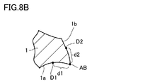
- FIG. 8B is a partially enlarged view of FIG. 8A.
- FIG. 8A is a cross-sectional view taken along line YY shown in FIG.
- FIG. 8B is a partially enlarged view of FIG. 8A.
- the present disclosure has been made in view of the above circumstances, and an object thereof is to provide a surface-coated cutting tool having excellent fracture resistance and excellent wear resistance.
- a surface-coated cutting tool includes: A substrate including a rake face and a flank face; A first coating covering the rake face; A second coating covering the flank; A surface-coated cutting tool comprising: The first coating includes a first composite nitride layer in the region d1 on the rake face, The second coating includes a second composite nitride layer in the region d2 on the flank, It said first composite nitride layer, Ti 1-x1-y1 Al x1 Ta y1 C ⁇ 1 N ⁇ 1 (although, x1, y1, ⁇ 1 and .beta.1 each represent atomic ratios, x1 is 0.4 ⁇ x1 ⁇ 0.
- the second composite nitride layer includes Ti 1-x2-y2 Al x2 Ta y2 C ⁇ 2 N ⁇ 2 (where x2, y2, ⁇ 2, and ⁇ 2 each represent an atomic ratio, and x2 is 0.45 ⁇ x2 ⁇ 0.
- the region d1 is formed from the virtual ridge line formed by intersecting the rake face and the flank face.
- the surface-coated cutting tool can have a rake face excellent in hardness and toughness and a flank face excellent in hardness at the same time by having the above-described configuration. As a result, the surface-coated cutting tool has excellent fracture resistance and excellent wear resistance.
- the above y1 is 0.03 ⁇ y1 ⁇ 0.05. By defining in this way, it becomes a surface-coated cutting tool that is further excellent in fracture resistance and wear resistance.
- y2 is 0.08 ⁇ y2 ⁇ 0.1.
- the above x1 is 0.4 ⁇ x1 ⁇ 0.5. By defining in this way, it becomes a surface-coated cutting tool that is further excellent in fracture resistance and wear resistance.
- Each of the first coating and the second coating has a thickness of 1 ⁇ m or more and 10 ⁇ m or less. By defining in this way, it becomes a surface-coated cutting tool that is further excellent in fracture resistance and wear resistance.
- the base material includes at least one selected from the group consisting of cemented carbide, cermet, high speed steel, ceramics, cBN sintered body, and diamond sintered body.
- the chemical formula includes any conventionally known composition (element ratio). Shall be.
- the chemical formula includes not only the stoichiometric composition but also the non-stoichiometric composition.
- the chemical formula of “TiC” includes not only the stoichiometric composition “Ti 1 C 1 ” but also a non-stoichiometric composition such as “Ti 1 C 0.8 ”. The same applies to the description of compounds other than “TiC”.
- the surface-coated cutting tool is A substrate including a rake face and a flank face; A first coating covering the rake face; A second coating covering the flank; A surface-coated cutting tool comprising: The first coating includes a first composite nitride layer in the region d1 on the rake face, The second coating includes a second composite nitride layer in the region d2 on the flank, It said first composite nitride layer, Ti 1-x1-y1 Al x1 Ta y1 C ⁇ 1 N ⁇ 1 (although, x1, y1, ⁇ 1 and .beta.1 each represent atomic ratios, x1 is 0.4 ⁇ x1 ⁇ 0.
- the second composite nitride layer includes Ti 1-x2-y2 Al x2 Ta y2 C ⁇ 2 N ⁇ 2 (where x2, y2, ⁇ 2, and ⁇ 2 each represent an atomic ratio, and x2 is 0.45 ⁇ x2 ⁇ 0.
- the region d1 is formed from the virtual ridge line formed by intersecting the rake face and the flank face.
- the surface-coated cutting tool of the present embodiment includes a base material and a coating (first coating and second coating) that covers the base material.
- the cutting tool includes, for example, a drill, an end mill (for example, a ball end mill), a cutting edge exchangeable cutting tip for a drill, a cutting edge exchangeable cutting tip for an end mill, a cutting edge exchangeable cutting tip for milling, and a cutting edge exchangeable cutting tip for turning.
- Cermet (mainly composed of TiC, TiN, TiCN, etc.), high speed steel, ceramics (titanium carbide, silicon carbide, silicon nitride, aluminum nitride, aluminum oxide, etc.), cubic crystal It is preferable to include at least one selected from the group consisting of a type boron nitride sintered body (cBN sintered body) and a diamond sintered body, and at least one selected from the group consisting of cemented carbide, cermet and cBN sintered body. More preferably it contains a seed.
- WC-based cemented carbide or cermet particularly TiCN-based cermet. This is because these substrates are particularly excellent in the balance between hardness and strength at high temperatures, and have excellent characteristics as substrates for surface-coated cutting tools for the above applications.
- the effect of this embodiment is shown even if such a cemented carbide includes an abnormal phase called free carbon or ⁇ phase in the structure.
- the base material used in this embodiment may have a modified surface.
- a de- ⁇ layer may be formed on the surface, or in the case of cermet, a surface hardened layer may be formed. Even if the surface is modified in this way, this embodiment The effect of is shown.
- the base material has a rake face and a flank face.
- "Rake face” means a face that scoops off chips cut from the work material.
- the “flank” means a surface that partially contacts the work material.
- the base material is classified into two types according to its shape: “when the rake face and the flank face are connected via the cutting edge face” or “when the rake face and the flank face are connected via a ridge line”. . In the following, description will be given using a blade-tip-exchangeable cutting tip (FIGS. 1 to 6) and a rotary tool (FIGS. 7, 8A and 8B) as specific examples.
- the cutting tool 10 shown in FIG. 1 and FIG. 2 has a surface including an upper surface, a lower surface, and four side surfaces, and as a whole, has a rectangular column shape that is slightly thin in the vertical direction. Further, the cutting tool 10 is formed with a through-hole penetrating the upper and lower surfaces, and adjacent side surfaces are connected by an arc surface at a boundary portion between the four side surfaces.
- the upper surface and the lower surface form the rake face 1a
- the four side faces (and the arc faces connecting them to each other) form the flank face 1b
- the arc faces connecting the rake face 1a and the flank face 1b. Forms the cutting edge surface 1c.
- FIG. 3 is a partially enlarged view of FIG.
- a virtual plane A corresponds to a surface obtained by extending the rake face 1a.
- the boundary line AA is a boundary line between the rake face 1a and the cutting edge face 1c.
- the virtual plane B corresponds to a surface obtained by extending the flank 1b.
- the boundary line BB is a boundary line between the flank 1b and the cutting edge surface 1c.
- the virtual ridge line AB ′ is an intersection line between a surface (virtual plane A) obtained by extending the rake face 1a and a surface (virtual plane B) obtained by extending the flank 1b. That is, the virtual plane A and the virtual plane B intersect to form a virtual ridge line AB ′.
- the cutting edge surface 1c is a circular arc surface (honing), and the rake face 1a and the flank face 1b are connected via the cutting edge face 1c.
- a portion of the rake face 1 a and the flank 1 b adjacent to the cutting edge surface 1 c and the cutting edge surface 1 c form a cutting edge portion of the cutting tool 10.
- the virtual plane A and the virtual plane B are shown as lines, and the boundary line AA, the boundary line BB, and the virtual ridge line AB ′ are shown as dots.
- FIGS. 1 to 3 show the case where the cutting edge surface 1c is an arcuate surface (honing), the shape of the cutting edge surface 1c is not limited to this.
- it may have a planar shape (negative land).
- FIG. 5 there may be a shape in which a flat surface and a circular arc surface are mixed (a shape in which honing and negative land are combined).
- the rake face 1 a and the flank face 1 b are connected via the blade edge face 1 c, and the virtual plane A, the boundary line AA, the virtual plane B, A boundary line BB and a virtual ridge line AB ′ are set. That is, the cases shown in FIGS. 3 to 5 are all included in the case where “the rake face and the flank face are connected via the cutting edge face”.
- the blade edge surface 1c can be determined only from the shape. This is because the cutting edge surface 1c in this case is not included in either the virtual plane A or the virtual plane B, and can be visually distinguished from the rake face 1a and the flank face 1b.
- the cutting edge surface 1c is generally the surface of the base material 1 and may include a surface formed by performing a machining process on the ridges of the intersecting surfaces.
- the substrate 1 is obtained by subjecting at least a part of the surface of the substrate precursor made of a sintered body or the like to machining, and the cutting edge surface 1c is chamfered by machining treatment.
- the surface formed through may be included.
- the base material 1 has a sharp edge shape as shown in FIG. 6, it is included in “when the rake face and the flank face are connected via a ridge line”.
- the cutting edge surface 1c shown in FIGS. 3 to 5 does not exist, and the rake face 1a and the flank face 1b are adjacent to each other.
- the boundary line between the rake face 1a and the flank face 1b forms a ridge line AB, and the ridge line AB and a part of the rake face 1a and the flank face 1b adjacent to the ridge line AB form a cutting edge part of the cutting tool 10.
- FIG. 7 is a schematic plan view illustrating a rotary tool that is another embodiment of the cutting tool.
- 8A is a cross-sectional view taken along the line YY shown in FIG. 7, and
- FIG. 8B is a partially enlarged view of FIG. 8A.
- a four-blade end mill is exemplified as such a rotary tool.
- a drill is cited as another aspect of such a rotary tool.
- the first coating 11a covers the rake face 1a (FIG. 12A). More specifically, the “first coating” covers at least a part of the rake face of the substrate. The first coating preferably covers the entire rake face. However, even if a part of the rake face is not covered with the first coating or the configuration of the coating is partially different, it does not depart from the scope of the present embodiment.
- the first coating includes a first composite nitride layer in the region d1 on the rake face 1a.
- the first coating may be composed of a first composite nitride layer in the region d1.
- the first coating may be composed of a first composite nitride layer and one or more other layers in the region d1.
- the “other layers” will be described later.
- the region d1 is “200 ⁇ m on the rake face 1a from the virtual ridge line AB ′”.
- the first film in the present embodiment may include the first composite nitride layer in a region on the rake face and in a region other than the region d1.
- the first coating may include the first composite nitride layer over the entire rake face.
- the first coating may include one or more other layers in a region other than the region d1.
- the “first composite nitride layer” will be described later.
- the thickness of the first coating is preferably 1 ⁇ m or more and 10 ⁇ m or less, and more preferably 1 ⁇ m or more and 6 ⁇ m or less.
- the thickness of the first coating can be determined, for example, by a method using a scanning electron microscope (SEM). More specifically, first, arbitrary three points in the first film of the cross-sectional sample parallel to the normal direction of the surface of the substrate are measured. Next, the thickness of the first coating is obtained by taking the average value of the three measured thicknesses. The same applies to the thicknesses of the first composite nitride layer, the second coating, and the second composite nitride layer, which will be described later.
- Examples of the scanning electron microscope include JSM-IT300 (trade name) manufactured by JEOL Ltd.
- the composition of the first composite nitride layer can be obtained, for example, by performing energy dispersive X-ray analysis (EDX analysis) performed under the following conditions. Specifically, first, when the base material 1 (that is, the cutting tool 10) is a blade-tip-exchangeable cutting tip having a sharp edge shape as shown in FIG. 6, the ridge line AB is separated from the ridge line AB by 200 ⁇ m. EDX measurement is performed on any three points (for example, FIG. 9) in the region d1 sandwiched between the imaginary line D1, and the average value of atomic% of Al, Ti, and Ta is obtained. Next, the composition ratio of each of Al, Ti and Ta is obtained based on the obtained average value of atomic%.
- EDX analysis energy dispersive X-ray analysis
- composition ratio of Al when the composition ratio of Al is obtained, it can be obtained by the following formula (1).
- M Al , M Ti and M Ta represent average values of atomic% of Al, Ti and Ta, respectively.
- the composition ratios of other metal elements Ti and Ta can be obtained by the same method.
- Al composition ratio M Al / (M Al + M Ti + M Ta ) Formula (1)
- the composition ratio of the nonmetallic elements N and C in the first composite nitride layer can also be obtained by the above method.
- An example of the EDX apparatus is JED-2300 Analysis Station Plus (trade name) manufactured by JEOL Ltd.
- the composition ratio of each element obtained based on the above method is defined as the composition ratio of each element in the region d1 of the rake face 1a (FIG. 9).
- the composition ratio of each element in the region d1 of the rake face 1a (FIG. 9).
- three points on the virtual line D1 are selected in FIG. 9, but any three points may be selected within the region d1.
- the “arbitrary three points” are selected from different crystal grains in the first composite nitride layer.
- the average value of the atomic% of each element obtained in step 1 is defined as the atomic% of each element in the rake face region d1.
- the composition ratio obtained based on the atomic% of each element is defined as the composition ratio in the region d1 of the rake face.
- the composition of the first composite nitride layer can be obtained by the method described above.
- the region d1 of the rake face 1a is specified based on a cross section (FIG. 8A) cut along a plane perpendicular to the rotation axis of the rotary tool. That is, the region d1 can be grasped as a region sandwiched between the ridge line AB and a virtual line D1 that is 200 ⁇ m away from the ridge line AB along the surface of the groove 1a (FIG. 8B).
- x1 is 0.4 ⁇ x1 ⁇ 0.6, preferably 0.4 ⁇ x1 ⁇ 0.5, and 0.45 ⁇ x1 ⁇ 0.5. It is more preferable.
- wear resistance such as crater wear resistance is improved.
- the above x1 is less than 0.4, the oxidation resistance tends to decrease.
- y1 is 0.01 ⁇ y1 ⁇ 0.05, preferably 0.03 ⁇ y1 ⁇ 0.05, and 0.03 ⁇ y1 ⁇ 0.04. It is more preferable.
- y1 is within the above range, the high-temperature hardness of the first composite nitride layer is increased, and wear resistance such as crater wear resistance is improved.
- y1 exceeds 0.05, the compressive stress of the first composite nitride layer decreases, and chipping such as film chipping tends to occur.
- the ⁇ 1 is 0 ⁇ ⁇ 1 ⁇ 0.4, preferably 0 ⁇ ⁇ 1 ⁇ 0.3, and more preferably 0 ⁇ ⁇ 1 ⁇ 0.2.
- the first composite nitride layer can be grasped as a first composite carbonitride layer containing composite carbonitride.
- ⁇ 1 is preferably 0.4 ⁇ 1 ⁇ 1.2, and more preferably 0.8 ⁇ ⁇ 1 ⁇ 1.2.
- ⁇ 1 + ⁇ 1 is 0.8 ⁇ ⁇ 1 + ⁇ 1 ⁇ 1.2, preferably 0.85 ⁇ ⁇ 1 + ⁇ 1 ⁇ 1.15, and 0.9 ⁇ ⁇ 1 + ⁇ 1 ⁇ 1.1. It is more preferable.
- the thickness of the first composite nitride layer is preferably 1 ⁇ m or more and 8 ⁇ m or less, and more preferably 1 ⁇ m or more and 6 ⁇ m or less.
- the thickness of the first composite nitride layer can be determined by a method using SEM, for example, as described above.
- the second coating 11b covers the flank 1b (FIG. 12B). More specifically, the “second coating” covers at least a part of the flank in the substrate. The second coating preferably covers the entire flank. However, even if a part of the flank is not covered with the second coating or the configuration of the coating is partially different, it does not depart from the scope of the present embodiment.
- the second coating includes a second composite nitride layer in the region d2 on the flank 1b.
- the second coating may be composed of a second composite nitride layer in the region d2.
- the second coating may be composed of a second composite nitride layer and one or more other layers in the region d2.
- the “other layers” will be described later.
- the region d2 is “200 ⁇ m on the flank 1b from the virtual ridge line AB ′”.
- the second coating film in the present embodiment may include the second composite nitride layer in a region on the flank and other than the region d2.
- the second coating may include the second composite nitride layer over the entire flank.
- the second coating may include one or more other layers in a region other than the region d2. The “second composite nitride layer” will be described later.
- the thickness of the second coating is preferably 1 ⁇ m or more and 10 ⁇ m or less, more preferably 1 ⁇ m or more and 8 ⁇ m or less, and further preferably 1 ⁇ m or more and 6 ⁇ m or less.
- the thickness of the second coating can be determined by a method using SEM, for example, as described above.
- the composition of the second composite nitride layer can be obtained by the method described above.
- the region d2 of the flank 1b is specified based on a cross section (FIG. 8A) cut along a plane perpendicular to the rotation axis of the rotary tool. That is, the region d2 can be grasped as a region sandwiched between the ridge line AB and a virtual line D2 that is 200 ⁇ m away from the ridge line AB along the surface of the outer peripheral portion 1b (FIG. 8B).
- x2 is 0.45 ⁇ x2 ⁇ 0.65, preferably 0.55 ⁇ x2 ⁇ 0.65, and is 0.55 ⁇ x2 ⁇ 0.6. It is more preferable.
- x2 is within the above range, the hardness of the second composite nitride layer is increased, and wear resistance such as flank wear resistance is improved.
- x2 exceeds 0.65, the crystal structure in the second composite nitride layer becomes a hexagonal crystal and the hardness tends to decrease.
- y2 is 0.05 ⁇ y2 ⁇ 0.1, preferably 0.08 ⁇ y2 ⁇ 0.1, and 0.08 ⁇ y2 ⁇ 0.09. It is more preferable.
- y2 is within the above range, the hardness and high-temperature hardness of the second composite nitride layer are improved, and wear resistance such as flank wear resistance is improved.
- y2 exceeds 0.1, the hardness of the second composite nitride layer is excessively increased, and thus chipping such as film chipping tends to occur.
- ⁇ 2 is 0 ⁇ ⁇ 2 ⁇ 0.4, preferably 0 ⁇ ⁇ 2 ⁇ 0.3, and more preferably 0 ⁇ ⁇ 2 ⁇ 0.2.
- the second composite nitride layer can be grasped as a second composite carbonitride layer containing composite carbonitride.
- ⁇ 2 is preferably 0.4 ⁇ 2 ⁇ 1.2, and more preferably 0.8 ⁇ ⁇ 2 ⁇ 1.2.
- the method for manufacturing the surface-coated cutting tool according to the present embodiment is as follows. Preparing a base material, a base material preparation step; A first coating step of coating at least a part of the rake face with the first composite nitride layer; A second coating step of coating at least a part of the flank with the second composite nitride layer.
- a base material preparation step Preparing a base material, a base material preparation step; A first coating step of coating at least a part of the rake face with the first composite nitride layer; A second coating step of coating at least a part of the flank with the second composite nitride layer.
- the substrate is prepared.
- the base material any of those conventionally known as this type of base material can be used as described above.
- a raw material powder having a predetermined composition (mass%) is uniformly mixed using a commercially available attritor, and then the mixed powder is formed into a predetermined shape.
- the molded body of the raw material powder is sintered at 1300 to 1500 ° C. or lower for 1 to 2 hours in a predetermined sintering furnace, whereby the base material made of the cemented carbide can be obtained.
- the said base material may use a commercially available thing as it is.
- first coating step at least a part of the rake face is coated with the first composite nitride layer.
- “at least a part of the rake face” is an area on the rake face 1a, and is a virtual line that is 200 ⁇ m away from the ridge line AB and the ridge line AB that the rake face 1a and the flank 1b intersect.
- a region d1 sandwiched between the lines D1 is included (for example, FIG. 6).
- “at least a part of the rake face” is a region in the rake face 1a, and includes the boundary line AA between the rake face 1a and the cutting edge face 1c, and the rake face 1a. It includes a region d1 sandwiched between a virtual line D1 that is 200 ⁇ m away from a virtual ridge line AB ′ formed by intersecting the virtual plane A and the virtual plane B including the flank 1b (for example, FIGS. 3 to 5).
- the method for covering at least a part of the rake face with the first composite nitride layer is not particularly limited, and for example, the first composite nitride layer may be formed by physical vapor deposition (PVD method). .
- a conventionally known physical vapor deposition method can be used without any particular limitation.
- Examples of such physical vapor deposition include sputtering, ion plating, arc ion plating, and electron ion beam vapor deposition.
- the cathode arc ion plating method or sputtering method with a high ion ratio of the raw material element is used, it becomes possible to perform metal or gas ion bombardment treatment on the substrate surface before forming the coating film. This is preferable because the adhesiveness is greatly improved.
- the first composite nitride layer is formed by the arc ion plating method
- the following conditions can be given. That is, first, a target (sintered or melted target) containing Al, Ti and Ta is set in an arc evaporation source in the apparatus, the substrate (base material) temperature is set to 400 to 600 ° C., and the gas in the apparatus The pressure is set to 1-10 Pa.
- a mixed gas of nitrogen gas and argon gas is introduced as the gas.
- the mixed gas may further contain methane gas.
- an arc current of 100 to 180 A is supplied to the cathode electrode while changing the bias voltage of the substrate (negative) set in the apparatus so that the absolute value of the voltage increases in the range of ⁇ 50 to ⁇ 150V.
- the apparatus used for the arc ion plating method include AIP-S40 (trade name) manufactured by Kobe Steel.
- composition of the target used for forming the first composite nitride layer examples include Al (0.4 to 0.6 atomic%), Ti (0.35 to 0.59 atomic%), and Ta ( 0.1 to 0.5 atomic%).
- ⁇ Second coating step> In the second coating step, at least a part of the flank is coated with the second composite nitride layer.
- “at least a part of the flank” is a region on the flank 1b, which is a ridge line AB intersecting the rake face 1a and the flank 1b, and a virtual distance 200 ⁇ m away from the ridge line AB.
- a region d2 sandwiched between the lines D2 is included (for example, FIG. 6).
- “at least a part of the flank” is a region in the flank 1b, and is defined by a boundary line BB between the flank 1b and the blade edge surface 1c, and the virtual ridge line AB ′. It includes a region d2 sandwiched between virtual lines D2 separated by 200 ⁇ m (for example, FIGS. 3 to 5).
- the method for covering at least a part of the flank with the second composite nitride layer is not particularly limited, and for example, the second composite nitride layer may be formed by physical vapor deposition.
- the physical vapor deposition method a conventionally known physical vapor deposition method can be used without any particular limitation in the same manner as the first coating step described above.
- a cathode arc ion plating method may be used as the physical vapor deposition method.
- the first coating step and the second coating step may be performed simultaneously, or the second coating step may be performed after the first coating step. Moreover, you may perform the said 1st coating process after performing the said 2nd coating process.
- the method of performing as follows is mentioned. That is, as shown in FIG. 10, first, the target A corresponding to the first composite nitride layer and the target B corresponding to the second composite nitride layer are placed at different positions. Next, a base material (for example, a base material having the shape of a blade-tip-exchangeable cutting tip shown in FIG. 1) is installed so that the rake face 1a faces the target A and the flank face 1b faces the target B. The first coating step and the second coating step are performed simultaneously. More specifically, on the same wall surface of the chamber used for film formation, the target A is installed in the upper part and the target B is installed in the lower part.
- a base material for example, a base material having the shape of a blade-tip-exchangeable cutting tip shown in FIG.
- the rake face 1a and the flank face 1b are at an angle of 45 ° with respect to the wall surface of the chamber so that the rake face 1a faces the target A and the flank face 1b faces the target B.
- a substrate is placed and film formation is performed.
- the first composite nitride layer is also formed on the other rake face 1a, the orientation of the base material is changed so that the other rake face 1a faces the target A, and then formed by the same method as described above.
- a film may be formed.
- the commercially available commercially available which can be used as a masking agent or a masking agent to the outer peripheral part 1b of the rotary tool which is a base material first.
- the said outer peripheral part 1b is coat
- a first composite nitride layer is formed in the groove 1a using the target A (first covering step).
- the masking agent in the outer peripheral portion 1b is removed with a dedicated remover or a solvent such as alcohol or acetone.
- the manufacturing method according to this embodiment as described above, composite nitride layers having different Ta concentrations are separately formed on each of the rake face and the flank face. Therefore, it is possible to form composite nitride layers that match the characteristics required for each of the rake face and the flank face. That is, the manufacturing method according to the present embodiment can manufacture a surface-coated cutting tool having a rake face excellent in hardness and toughness and a flank face excellent in hardness at the same time by having the above-described configuration. It becomes possible.
- Appendix 1 A base material including a rake face, a flank face, and a cutting edge portion connecting the rake face and the flank face; A first coating covering the rake face; A second coating covering the flank; A surface-coated cutting tool comprising: The first coating is a region on the rake face, and is a first area in a region d1 sandwiched between a ridge line formed by intersecting the rake face and the flank face and a virtual line D1 separated from the ridge line by 200 ⁇ m.
- the second coating includes a second composite nitride layer in a region d2 between the ridgeline and a virtual line D2 that is 200 ⁇ m away from the ridgeline, in the flank area.
- the first composite nitride layer includes Ti 1-x1-y1 Al x1 Ta y1 C ⁇ 1 N ⁇ 1 (where x1, y1, ⁇ 1, and ⁇ 1 each represents an atomic ratio, and x1 is 0.4 ⁇ x1 ⁇ 0.
- a carbide ball end mill ( ⁇ 6) having a JIS standard of “GSXB20300” (manufactured by Sumitomo Electric Hardmetal Co., Ltd., trade name: GSXB20300, non-coated product) was prepared as a base material.
- a first composite nitride layer was formed on the groove (rake face) of the base material by arc ion plating. Specifically, the following method was used. First, the said outer peripheral part was coat
- the substrate temperature was set to 400 to 600 ° C.
- the gas pressure in the apparatus was set to 1.0 to 10.0 Pa.
- a mixed gas of nitrogen gas and argon gas was introduced when forming a nitride layer.
- a mixed gas of nitrogen gas, methane gas, and argon gas was introduced. Then, an arc current of 100 to 180 A was supplied to the cathode electrode while changing the substrate (negative) bias voltage so that the absolute value of the voltage increased in the range of ⁇ 50 to ⁇ 150V.
- the masking agent covering the outer peripheral portion was removed with a dedicated remover.
- a second composite nitride layer was formed on the outer peripheral portion (flank) of the substrate by arc ion plating.
- the following method was used.
- the said groove part was coat
- the base material was set in an arc ion plating apparatus.
- a target sintered target or melt target
- the substrate temperature was set to 400 to 600 ° C.
- the gas pressure in the apparatus was set to 1.0 to 10.0 Pa.
- a mixed gas of nitrogen gas and argon gas was introduced when forming a nitride layer.
- a mixed gas of nitrogen gas, methane gas, and argon gas was introduced. Then, an arc current of 100 to 180 A was supplied to the cathode electrode while changing the substrate (negative) bias voltage so that the absolute value of the voltage increased in the range of ⁇ 50 to ⁇ 150V.
- a second film composed of the second composite nitride layer was formed by generating metal ions and the like from the arc evaporation source. After the second coating was formed, the masking agent covering the groove was removed with a special removing agent.
- the composition of the first coating (first composite nitride layer) and the second coating (second composite nitride layer) was determined by using the above sample, and an EDX device attached to SEM (manufactured by JEOL Ltd., trade name: JED). -2300 Analysis Station Plus) under the following conditions.
- SEM manufactured by JEOL Ltd., trade name: JED
- -2300 Analysis Station Plus a specific example, first, based on a cross section (for example, FIG.
- composition ratio of the first coating indicates the composition ratio of each element.
- an element not having a numeral indicates that the composition ratio of the element is 1.
- Ti0.50Al0.50N means that the composition ratio of Ti element and Al element is 0.50, and the composition ratio of N element is 1.
- the thickness of the first coating (first composite nitride layer) and the second coating (second composite nitride layer) was determined by scanning electron microscope (SEM) (trade name: JSM-IT300, manufactured by JEOL Ltd.). It was determined by measuring three arbitrary points in the cross-sectional sample parallel to the normal direction of the surface of the base material and taking the average value of the measured thicknesses of the three points. The results are shown in Tables 1 to 3.
- the numerical values in the “film thickness” column in Tables 1 to 3 mean the average value of the film thickness on the rake face and the film thickness on the flank face.
- SEM measurement conditions Acceleration voltage: 10 kV Irradiation current: 40 ⁇ A Magnification: 10,000 times
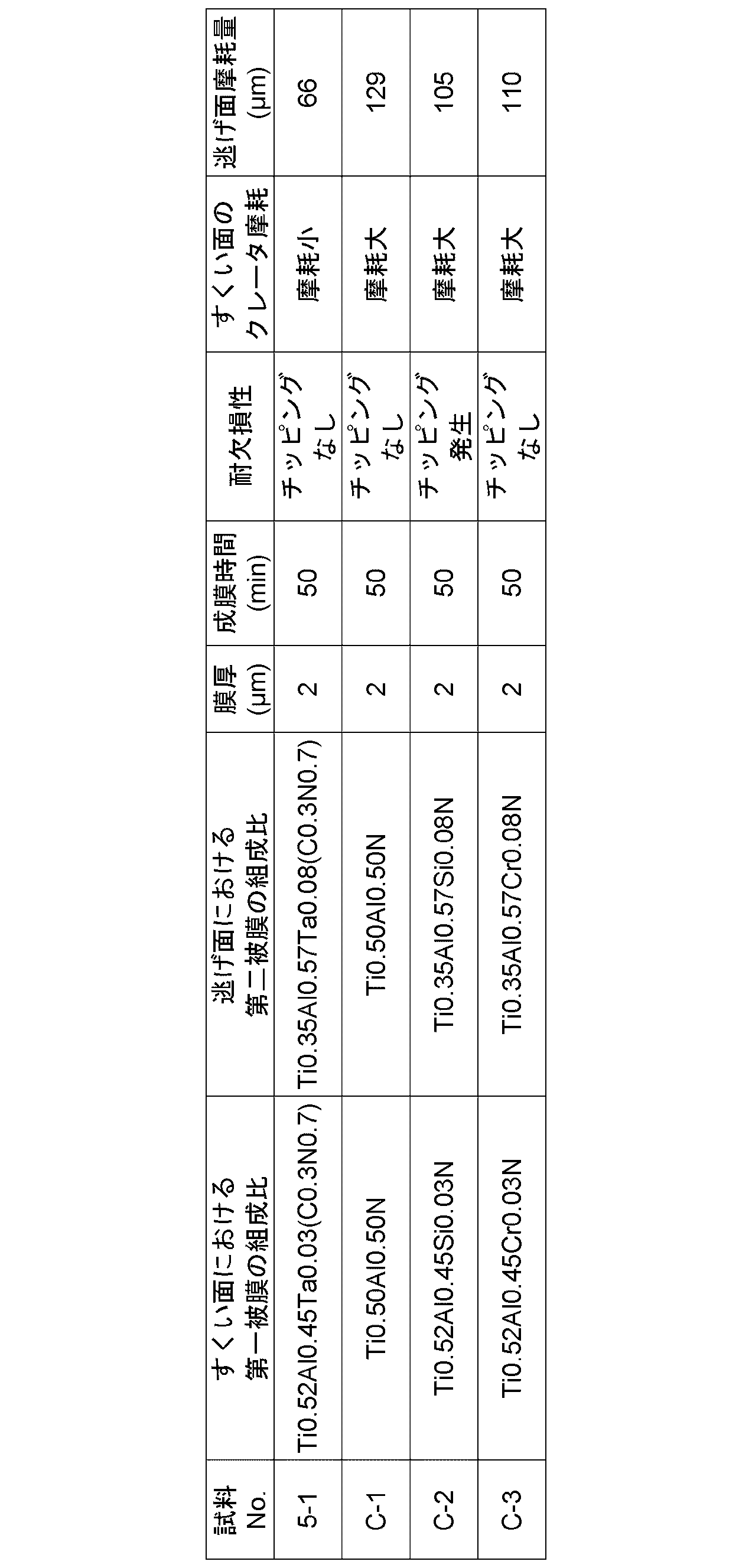
- the cutting tool according to -1 has superior fracture resistance and superior wear resistance (crater wear resistance and flank wear resistance) compared to the cutting tool of the comparative example. It was.
Landscapes
- Chemical & Material Sciences (AREA)
- Engineering & Computer Science (AREA)
- Mechanical Engineering (AREA)
- Chemical Kinetics & Catalysis (AREA)
- Materials Engineering (AREA)
- Metallurgy (AREA)
- Organic Chemistry (AREA)
- Inorganic Chemistry (AREA)
- Ceramic Engineering (AREA)
- Cutting Tools, Boring Holders, And Turrets (AREA)
- Physical Vapour Deposition (AREA)
- Chemical Vapour Deposition (AREA)
Abstract
Description
すくい面と、逃げ面とを含む基材と、
上記すくい面を被覆する第一被膜と、
上記逃げ面を被覆する第二被膜と、
を備える表面被覆切削工具であって、
上記第一被膜は、上記すくい面における領域d1において、第一複合窒化物層を含み、
上記第二被膜は、上記逃げ面における領域d2において、第二複合窒化物層を含み、
上記第一複合窒化物層は、Ti1-x1-y1Alx1Tay1Cα1Nβ1(ただし、x1、y1、α1及びβ1はそれぞれ原子比を示し、x1は0.4≦x1≦0.6であり、y1は0.01≦y1≦0.05であり、α1は0≦α1≦0.4であり、α1+β1は0.8≦α1+β1≦1.2である)を含み、
上記第二複合窒化物層は、Ti1-x2-y2Alx2Tay2Cα2Nβ2(ただし、x2、y2、α2及びβ2はそれぞれ原子比を示し、x2は0.45≦x2≦0.65であり、y2は0.05<y2≦0.1であり、α2は0≦α2≦0.4であり、α2+β2は0.8≦α2+β2≦1.2である)を含み、
上記すくい面と上記逃げ面とが刃先面を介して繋がっている場合は、上記領域d1は、上記すくい面を延長した面と上記逃げ面を延長した面とが交差してなる仮想稜線から上記すくい面上で200μm離れた仮想線D1と、上記すくい面と上記刃先面との境界線と、で挟まれた領域であり、かつ、上記領域d2は、上記仮想稜線から上記逃げ面上で200μm離れた仮想線D2と、上記逃げ面と上記刃先面との境界線と、で挟まれた領域であり、
上記すくい面と上記逃げ面とが稜線を介して繋がっている場合は、上記領域d1は、上記稜線から上記すくい面上で200μm離れた仮想線D1と、上記稜線と、で挟まれた領域であり、かつ、上記領域d2は、上記稜線から上記逃げ面上で200μm離れた仮想線D2と、上記稜線と、で挟まれた領域である。
特許文献1では、基材の表面に硬質な被膜を設けることによって、切削工具の性能(例えば、耐欠損性、耐摩耗性等)を向上させている。しかしながら、切削工具におけるすくい面及び逃げ面は、それぞれ異なる性能が求められているにも関わらず、特許文献1に記載の切削工具ではすくい面及び逃げ面共に同質の被膜が設けられている。そのため、上記被膜を設けることによって、例えばすくい面の性能は向上したとしても、逃げ面の性能が不充分である等の場合が生じている。
上記によれば、優れた耐欠損性を有し、且つ優れた耐摩耗性を有する表面被覆切削工具を提供することが可能になる。
最初に本開示の一態様の内容を列記して説明する。
[1]本開示の一態様に係る表面被覆切削工具は、
すくい面と、逃げ面とを含む基材と、
上記すくい面を被覆する第一被膜と、
上記逃げ面を被覆する第二被膜と、
を備える表面被覆切削工具であって、
上記第一被膜は、上記すくい面における領域d1において、第一複合窒化物層を含み、
上記第二被膜は、上記逃げ面における領域d2において、第二複合窒化物層を含み、
上記第一複合窒化物層は、Ti1-x1-y1Alx1Tay1Cα1Nβ1(ただし、x1、y1、α1及びβ1はそれぞれ原子比を示し、x1は0.4≦x1≦0.6であり、y1は0.01≦y1≦0.05であり、α1は0≦α1≦0.4であり、α1+β1は0.8≦α1+β1≦1.2である)を含み、
上記第二複合窒化物層は、Ti1-x2-y2Alx2Tay2Cα2Nβ2(ただし、x2、y2、α2及びβ2はそれぞれ原子比を示し、x2は0.45≦x2≦0.65であり、y2は0.05<y2≦0.1であり、α2は0≦α2≦0.4であり、α2+β2は0.8≦α2+β2≦1.2である)を含み、
上記すくい面と上記逃げ面とが刃先面を介して繋がっている場合は、上記領域d1は、上記すくい面を延長した面と上記逃げ面を延長した面とが交差してなる仮想稜線から上記すくい面上で200μm離れた仮想線D1と、上記すくい面と上記刃先面との境界線と、で挟まれた領域であり、かつ、上記領域d2は、上記仮想稜線から上記逃げ面上で200μm離れた仮想線D2と、上記逃げ面と上記刃先面との境界線と、で挟まれた領域であり、
上記すくい面と上記逃げ面とが稜線を介して繋がっている場合は、上記領域d1は、上記稜線から上記すくい面上で200μm離れた仮想線D1と、上記稜線と、で挟まれた領域であり、かつ、上記領域d2は、上記稜線から上記逃げ面上で200μm離れた仮想線D2と、上記稜線と、で挟まれた領域である。
以下、本開示の一実施形態(以下「本実施形態」と記す。)について説明する。ただし、本実施形態はこれに限定されるものではない。なお以下の実施形態の説明に用いられる図面において、同一の参照符号は、同一部分または相当部分を表わす。本明細書において「A~B」という形式の表記は、範囲の上限下限(すなわちA以上B以下)を意味し、Aにおいて単位の記載がなく、Bにおいてのみ単位が記載されている場合、Aの単位とBの単位とは同じである。さらに、本明細書において、たとえば「TiC」等のように、構成元素の比が限定されていない化学式によって化合物が表された場合には、その化学式は従来公知のあらゆる組成(元素比)を含むものとする。このとき化学式は、化学量論組成のみならず、非化学量論組成も含むものとする。たとえば「TiC」の化学式には、化学量論組成「Ti1C1」のみならず、たとえば「Ti1C0.8」のような非化学量論組成も含まれる。このことは、「TiC」以外の化合物の記載についても同様である。
本実施形態に係る表面被覆切削工具は、
すくい面と、逃げ面とを含む基材と、
上記すくい面を被覆する第一被膜と、
上記逃げ面を被覆する第二被膜と、
を備える表面被覆切削工具であって、
上記第一被膜は、上記すくい面における領域d1において、第一複合窒化物層を含み、
上記第二被膜は、上記逃げ面における領域d2において、第二複合窒化物層を含み、
上記第一複合窒化物層は、Ti1-x1-y1Alx1Tay1Cα1Nβ1(ただし、x1、y1、α1及びβ1はそれぞれ原子比を示し、x1は0.4≦x1≦0.6であり、y1は0.01≦y1≦0.05であり、α1は0≦α1≦0.4であり、α1+β1は0.8≦α1+β1≦1.2である)を含み、
上記第二複合窒化物層は、Ti1-x2-y2Alx2Tay2Cα2Nβ2(ただし、x2、y2、α2及びβ2はそれぞれ原子比を示し、x2は0.45≦x2≦0.65であり、y2は0.05<y2≦0.1であり、α2は0≦α2≦0.4であり、α2+β2は0.8≦α2+β2≦1.2である)を含み、
上記すくい面と上記逃げ面とが刃先面を介して繋がっている場合は、上記領域d1は、上記すくい面を延長した面と上記逃げ面を延長した面とが交差してなる仮想稜線から上記すくい面上で200μm離れた仮想線D1と、上記すくい面と上記刃先面との境界線と、で挟まれた領域であり、かつ、上記領域d2は、上記仮想稜線から上記逃げ面上で200μm離れた仮想線D2と、上記逃げ面と上記刃先面との境界線と、で挟まれた領域であり、
上記すくい面と上記逃げ面とが稜線を介して繋がっている場合は、上記領域d1は、上記稜線から上記すくい面上で200μm離れた仮想線D1と、上記稜線と、で挟まれた領域であり、かつ、上記領域d2は、上記稜線から上記逃げ面上で200μm離れた仮想線D2と、上記稜線と、で挟まれた領域である。ここで、α1≠0のとき、上記第一複合窒化物層は、複合炭窒化物を含む第一複合炭窒化物層として把握できる。また、α2≠0のとき、上記第二複合窒化物層は、複合炭窒化物を含む第二複合炭窒化物層として把握できる。
本実施形態の基材は、この種の基材として従来公知のものであればいずれのものも使用することができる。例えば、上記基材は、超硬合金(例えば、炭化タングステン(WC)基超硬合金、WCの他にCoを含む超硬合金、WCの他にCr、Ti、Ta、Nb等の炭窒化物を添加した超硬合金等)、サーメット(TiC、TiN、TiCN等を主成分とするもの)、高速度鋼、セラミックス(炭化チタン、炭化珪素、窒化珪素、窒化アルミニウム、酸化アルミニウム等)、立方晶型窒化硼素焼結体(cBN焼結体)及びダイヤモンド焼結体からなる群より選ばれる少なくとも1種を含むことが好ましく、超硬合金、サーメット及びcBN焼結体からなる群より選ばれる少なくとも1種を含むことがより好ましい。
図1は切削工具の一態様を例示する斜視図であり、図2は図1のX-X線に関する矢視断面図である。このような形状の切削工具は、旋削加工用刃先交換型切削チップ等の刃先交換型切削チップとして用いられる。
仮想平面Aはすくい面1aを延長した面に相当する。境界線AAはすくい面1aと刃先面1cとの境界線である。仮想平面Bは逃げ面1bを延長した面に相当する。境界線BBは逃げ面1bと刃先面1cとの境界線である。仮想稜線AB’はすくい面1aを延長した面(仮想平面A)と逃げ面1bを延長した面(仮想平面B)との交差線である。すなわち、仮想平面Aと仮想平面Bとが交差して仮想稜線AB’を成す。
図3に示す場合は、刃先面1cは円弧面(ホーニング)であり、すくい面1aと逃げ面1bとが刃先面1cを介して繋がっている。すくい面1aおよび逃げ面1bにおいて刃先面1cに隣接する部分、ならびに刃先面1cが切削工具10の刃先部を成す。
なお図3において、仮想平面Aおよび仮想平面Bは線状に示され、境界線AA、境界線BBおよび仮想稜線AB’は点状に示される。
図3に示す場合と同様に、図4および図5に示す場合においてもすくい面1aと逃げ面1bとが刃先面1cを介して繋がっており、仮想平面A、境界線AA、仮想平面B、境界線BBおよび仮想稜線AB’が設定される。
すなわち、図3から図5に示す場合は、いずれも「すくい面と逃げ面とが刃先面を介して繋がっている場合」に含まれる。
図6に示す場合、図3から図5に示す刃先面1cは存在せず、すくい面1aと逃げ面1bとが隣接している。また、すくい面1aと逃げ面1bとの境界線が稜線ABを成し、稜線ABならびにすくい面1aおよび逃げ面1bにおいて稜線ABに隣接する部分が切削工具10の刃先部を成す。
図7は、切削工具の他の一態様である回転工具を例示する概略平面図である。図8Aは、図7に示すY-Y線に関する矢視断面図であり、図8Bは、図8Aの部分拡大図である。本実施形態ではこのような回転工具として4枚刃のエンドミルが例示される。このような回転工具の他の態様としては、例えば、ドリルが挙げられる。
本実施形態において、第一被膜11aは上記すくい面1aを被覆する(図12A)。より詳細には、「第一被膜」は、上記基材における上記すくい面の少なくとも一部を被覆する。上記第一被膜は、上記すくい面の全面を被覆することが好ましい。しかしながら、上記すくい面の一部が上記第一被膜で被覆されていなかったり被膜の構成が部分的に異なっていたりしていたとしても本実施形態の範囲を逸脱するものではない。
ここで図3から図5に示すような「すくい面1aと逃げ面1bとが刃先面1cを介して繋がっている場合」には、領域d1は「仮想稜線AB’からすくい面1a上で200μm離れた仮想線D1と、すくい面1aと刃先面1cとの境界線AAと、で挟まれた領域」である。
一方、図6に示すような「すくい面1aと逃げ面1bとが稜線ABを介して繋がっている場合」には、領域d1は「稜線ABからすくい面1a上で200μm離れた仮想線D1と、稜線ABと、で挟まれた領域」である。
ここで本実施形態における上記第一被膜は、上記領域d1に加えて、上記すくい面における領域であって上記領域d1以外の領域において、上記第一複合窒化物層を含んでいてもよい。例えば、上記第一被膜は、上記すくい面全体において上記第一複合窒化物層を含んでいてもよい。本実施形態の一側面において、上記第一被膜は上記領域d1以外の領域において、1又は複数の他の層を含んでいてもよい。「第一複合窒化物層」については後述する。
上記第一複合窒化物層は、Ti1-x1-y1Alx1Tay1Cα1Nβ1を含む。ここで、x1、y1、α1及びβ1はそれぞれ原子比を示し、x1は0.4≦x1≦0.6であり、y1は0.01≦y1≦0.05であり、α1は0≦α1≦0.4であり、α1+β1は0.8≦α1+β1≦1.2である。上記第一複合窒化物層は、本実施形態に係る表面被覆切削工具が奏する効果を損なわない範囲において、不可避不純物が含まれていてもよい。上記不可避不純物の含有割合は、第一複合窒化物層の全質量に対して0質量%以上1質量%以下であることが好ましい。
Alの組成比=MAl/(MAl+MTi+MTa) 式(1)
また、上記第一複合窒化物層における非金属元素N及びCの組成比も上述の方法によって求めることが可能である。
上記EDX装置としては、例えば、日本電子株式会社製のJED-2300 Analysis Station Plus(商品名)が挙げられる。
加速電圧 :15kV
照射電流 :70μA
測定対象の元素 : Al、Ti、Ta、C、N
積算回数 :20回
本実施形態において、第二被膜11bは上記逃げ面1bを被覆する(図12B)。より詳細には、「第二被膜」は、上記基材における上記逃げ面の少なくとも一部を被覆する。上記第二被膜は、上記逃げ面の全面を被覆することが好ましい。しかしながら、上記逃げ面の一部が上記第二被膜で被覆されていなかったり被膜の構成が部分的に異なっていたりしていたとしても本実施形態の範囲を逸脱するものではない。
ここで図3から図5に示すような「すくい面1aと逃げ面1bとが刃先面1cを介して繋がっている場合」には、領域d2は「仮想稜線AB’から逃げ面1b上で200μm離れた仮想線D2と、逃げ面1bと刃先面1cとの境界線BBと、で挟まれた領域」である。
一方、図6に示すような「すくい面1aと逃げ面1bとが稜線ABを介して繋がっている場合」には、領域d2は「稜線ABから逃げ面1b上で200μm離れた仮想線D2と、稜線ABと、で挟まれた領域」である。
ここで本実施形態における上記第二被膜は、上記領域d2に加えて、上記逃げ面における領域であって上記領域d2以外の領域において、上記第二複合窒化物層を含んでいてもよい。例えば、上記第二被膜は、上記逃げ面全体において上記第二複合窒化物層を含んでいてもよい。本実施形態の一側面において、上記第二被膜は上記領域d2以外の領域において、1又は複数の他の層を含んでいてもよい。「第二複合窒化物層」については後述する。
上記第二複合窒化物層は、Ti1-x2-y2Alx2Tay2Cα2Nβ2を含む。ここで、x2、y2、α2及びβ2はそれぞれ原子比を示し、x2は0.45≦x2≦0.65であり、y2は0.05<y2≦0.1であり、α2は0≦α2≦0.4であり、α2+β2は0.8≦α2+β2≦1.2である。上記第二複合窒化物層は、本実施形態に係る表面被覆切削工具が奏する効果を損なわない範囲において、不可避不純物が含まれていてもよい。上記不可避不純物の含有割合は、第二複合窒化物層の全質量に対して0質量%以上1質量%以下であることが好ましい。
また、本実施形態の効果を損なわない範囲において、上記第一被膜及び上記第二被膜は、それぞれ他の層を更に含んでいてもよい。他の層としては、例えばTiN層(TiNで示される化合物からなる層、以下同様。)、TiBNO層、TiCNO層、TiB2層、TiAlN層、TiAlCN層、TiAlON層、TiAlONC層、Al2O3層等を挙げることができる。なお、上記他の層はその積層の順も特に限定されない。例えば、上記他の層は、上記基材と上記第一複合窒化物層との間に形成されていてもよいし、上記第一複合窒化物層上に形成されていてもよい。言い方を変えると上記第一複合窒化物層は上記第一被膜における最外層であってもよい。また、上記他の層は、上記基材と上記第二複合窒化物層との間に形成されていてもよいし、上記第二複合窒化物層上に形成されていてもよい。言い方を変えると上記第二複合窒化物層は上記第二被膜における最外層であってもよい。
本実施形態に係る表面被覆切削工具の製造方法は、
上記基材を準備する、基材準備工程と、
上記すくい面の少なくとも一部を、上記第一複合窒化物層で被覆する、第一被覆工程と、
上記逃げ面の少なくとも一部を、上記第二複合窒化物層で被覆する、第二被覆工程と、を含む。以下、各工程について説明する。
基材準備工程では、上記基材を準備する。上記基材としては、上述したようにこの種の基材として従来公知のものであればいずれのものも使用することができる。例えば、上記基材が超硬合金からなる場合、まず、所定の配合組成(質量%)からなる原料粉末を市販のアトライターを用いて均一に混合して、続いてこの混合粉末を所定の形状(例えば、CNMG120408NUXで示される形状、GSXB20300で示される形状等)に加圧成形する。その後、原料粉末の成形体を、所定の焼結炉において1300~1500℃以下で、1~2時間焼結することにより、超硬合金からなる上記基材を得ることができる。また、上記基材は、市販のものをそのまま用いてもよい。
第一被覆工程では、上記すくい面の少なくとも一部を上記第一複合窒化物層で被覆する。ここで、「すくい面の少なくとも一部」には、上記すくい面1aにおける領域であって、上記すくい面1aと上記逃げ面1bとが交差してなる稜線ABと上記稜線ABから200μm離れた仮想線D1とに挟まれた領域d1が含まれる(例えば、図6)。
第二被覆工程では、上記逃げ面の少なくとも一部を上記第二複合窒化物層で被覆する。ここで、「逃げ面の少なくとも一部」には、上記逃げ面1bにおける領域であって、上記すくい面1aと上記逃げ面1bとが交差してなる稜線ABと上記稜線ABから200μm離れた仮想線D2とに挟まれた領域d2が含まれる(例えば、図6)。
本実施形態に係る製造方法では、上述した工程の他にも、他の層を形成する工程等を適宜行ってもよい。上述の他の層を形成する場合、従来の方法によって他の層を形成してもよい。
以上の説明は、以下に付記する実施態様を含む。
(付記1)
すくい面と、逃げ面と、前記すくい面及び前記逃げ面を繋ぐ刃先部とを含む基材と、
前記すくい面を被覆する第一被膜と、
前記逃げ面を被覆する第二被膜と、
を備える表面被覆切削工具であって、
前記第一被膜は、前記すくい面における領域であって、前記すくい面と前記逃げ面とが交差してなる稜線と前記稜線から200μm離れた仮想線D1とに挟まれた領域d1において、第一複合窒化物層を含み、
前記第二被膜は、前記逃げ面における領域であって、前記稜線と前記稜線から200μm離れた仮想線D2とに挟まれた領域d2において、第二複合窒化物層を含み、
前記第一複合窒化物層は、Ti1-x1-y1Alx1Tay1Cα1Nβ1(ただし、x1、y1、α1及びβ1はそれぞれ原子比を示し、x1は0.4≦x1≦0.6であり、y1は0.01≦y1≦0.05であり、α1は0≦α1≦0.4であり、α1+β1は0.8≦α1+β1≦1.2である)を含み、
前記第二複合窒化物層は、Ti1-x2-y2Alx2Tay2Cα2Nβ2(ただし、x2、y2、α2及びβ2はそれぞれ原子比を示し、x2は0.45≦x2≦0.65であり、y2は0.05<y2≦0.1であり、α2は0≦α2≦0.4であり、α2+β2は0.8≦α2+β2≦1.2である)を含む、表面被覆切削工具。
<基材準備工程>
まず、基材準備工程として、JIS規格が「GSXB20300」である超硬のボールエンドミル(φ6)(住友電工ハードメタル株式会社製、商品名:GSXB20300、ノンコート品)を基材として準備した。
第一被覆工程として、アークイオンプレーティング法により、上記基材の溝部(すくい面)の上に第一複合窒化物層を形成した。具体的には以下の方法で行った。まず、上記基材の外周部(逃げ面)にマスキング剤を塗布することで、上記外周部を被覆した。その後、当該基材をアークイオンプレーティング装置(株式会社神戸製鋼所製、商品名:AIP-S40)にセットした。次に表1~3における「すくい面における第一被膜の組成比」の欄に記載の組成比で各金属元素を含むターゲット(焼結ターゲット又は溶成ターゲット)を装置内のアーク式蒸発源にセットした。このとき、基材温度を400~600℃及び該装置内のガス圧を1.0~10.0Paに設定した。上記ガスとしては、窒化物の層を形成する場合には窒素ガス及びアルゴンガスの混合ガスを導入した。上記ガスとしては、炭窒化物の層を形成する場合には、窒素ガス、メタンガス、及びアルゴンガスの混合ガスを導入した。そして、基板(負)バイアス電圧を-50~-150Vの範囲で電圧の絶対値が増大するように変化させながら、カソード電極に100~180Aのアーク電流を供給した。このようにアーク電流を供給することで、アーク式蒸発源から金属イオン等を発生させることにより第一複合窒化物層からなる第一被膜を形成した。上記第一被膜を形成した後に、上記外周部を被覆していたマスキング剤を専用の除去剤で除去した。
第二被覆工程として、アークイオンプレーティング法により、上記基材の外周部(逃げ面)の上に第二複合窒化物層を形成した。具体的には以下の方法で行った。まず、上記基材の溝部(すくい面)にマスキング剤を塗布することで、上記溝部を被覆した。その後、当該基材をアークイオンプレーティング装置にセットした。次に表1~3における「逃げ面における第二被膜の組成比」の欄に記載の組成比で各金属元素を含むターゲット(焼結ターゲット又は溶成ターゲット)を装置内のアーク式蒸発源にセットした。このとき、基材温度を400~600℃及び該装置内のガス圧を1.0~10.0Paに設定した。上記ガスとしては、窒化物の層を形成する場合には窒素ガス及びアルゴンガスの混合ガスを導入した。上記ガスとしては、炭窒化物の層を形成する場合には、窒素ガス、メタンガス、及びアルゴンガスの混合ガスを導入した。そして、基板(負)バイアス電圧を-50~-150Vの範囲で電圧の絶対値が増大するように変化させながら、カソード電極に100~180Aのアーク電流を供給した。このようにアーク電流を供給することで、アーク式蒸発源から金属イオン等を発生させることにより第二複合窒化物層からなる第二被膜を形成した。上記第二被膜を形成した後に、上記溝部を被覆していたマスキング剤を専用の除去剤で除去した。
上述のようにして作製した試料(試料No.1-1~1-7、2-1~2-7、3-1~3-7、4-1~4-7、5-1、及びC-1~C-3)の切削工具を用いて、以下のように、切削工具の各特性を評価した。
第一被膜(第一複合窒化物層)及び第二被膜(第二複合窒化物層)の組成は、上記試料を用いて、SEMに付帯のEDX装置(日本電子株式会社製、商品名:JED-2300 Analysis Station Plus)によって、以下の条件で測定した。具体例を挙げると、まず上記試料(回転工具)の回転軸に対して垂直な面で切断した断面(例えば、図8A)に基づいて、上記溝部(すくい面)における領域であって、上記溝部と上記外周部(逃げ面)とが交差してなる稜線と、上記溝部の表面に沿って上記稜線から200μm離れた仮想線D1とに挟まれた領域d1における任意の3点について、EDX測定を行い、Al、Ti及びTaそれぞれの原子%の平均値を求めた。なお、試料No.C-2及びC-3については、Taの代わりにそれぞれSi及びCrの原子%の平均値を求めた。ここで当該「任意の3点」は、上記第一複合窒化物層中の互いに異なる結晶粒から選択した。次に、求められた原子%の平均値に基づいて、Al、Ti及びTa(試料No.C-2及びC-3については、それぞれSi及びCr)それぞれの組成比を求めた。また、非金属元素であるN及びCそれぞれの組成比も同様の方法によって求めた。結果を表1~3に示す。
加速電圧 :15kV
照射電流 :70μA
測定対象の元素 : Al、Ti、Ta、C、N
積算回数 :20回
第一被膜(第一複合窒化物層)及び第二被膜(第二複合窒化物層)の厚さは、走査型電子顕微鏡(SEM)(日本電子株式会社製、商品名:JSM-IT300)を用いて、基材の表面の法線方向に平行な断面サンプルにおける任意の3点を測定し、測定された3点の厚さの平均値をとることで求めた。結果を表1~3に示す。表1~3における「膜厚」の欄の数値は、すくい面における被膜の膜厚と逃げ面における被膜の膜厚との平均値を意味する。
SEM法の測定条件
加速電圧 :10kV
照射電流 :40μA
倍率 :1万倍
<耐欠損性試験及び耐摩耗性試験>
上述のようにして作製した試料(試料No.1-1~1-7、2-1~2-7、3-1~3-7、4-1~4-7、5-1、及びC-1~C-3)の切削工具を用いて、以下の切削条件により切削試験を行うことで、耐欠損性及び耐摩耗性を評価した。具体的には、被削材を10m切削した後の刃先の状態を確認することで、耐欠損性及び耐摩耗性を評価した。その結果を表1~3に示す。本切削試験において、試料No.1-2~1-6、2-2~2-6、3-2~3-6、4-2~4-6及び5-1は実施例の試料であり、これら以外の試料は比較例の試料である。すなわち、試料No.1-1、1-7、2-1、2-7、3-1、3-7、4-1、4-7及びC-1~C-3は、比較例の試料である。
被削材(材質):インコネル718
速度(Vc) :45m/min
送り(fz) :0.05mm/t
切り込み :ap0.5mm、ae0.3mm
外部給油 :あり(水溶性)


Claims (7)
- すくい面と、逃げ面とを含む基材と、
前記すくい面を被覆する第一被膜と、
前記逃げ面を被覆する第二被膜と、
を備える表面被覆切削工具であって、
前記第一被膜は、前記すくい面における領域d1において、第一複合窒化物層を含み、
前記第二被膜は、前記逃げ面における領域d2において、第二複合窒化物層を含み、
前記第一複合窒化物層は、Ti1-x1-y1Alx1Tay1Cα1Nβ1(ただし、x1、y1、α1及びβ1はそれぞれ原子比を示し、x1は0.4≦x1≦0.6であり、y1は0.01≦y1≦0.05であり、α1は0≦α1≦0.4であり、α1+β1は0.8≦α1+β1≦1.2である)を含み、
前記第二複合窒化物層は、Ti1-x2-y2Alx2Tay2Cα2Nβ2(ただし、x2、y2、α2及びβ2はそれぞれ原子比を示し、x2は0.45≦x2≦0.65であり、y2は0.05<y2≦0.1であり、α2は0≦α2≦0.4であり、α2+β2は0.8≦α2+β2≦1.2である)を含み、
前記すくい面と前記逃げ面とが刃先面を介して繋がっている場合は、前記領域d1は、前記すくい面を延長した面と前記逃げ面を延長した面とが交差してなる仮想稜線から前記すくい面上で200μm離れた仮想線D1と、前記すくい面と前記刃先面との境界線と、で挟まれた領域であり、かつ、前記領域d2は、前記仮想稜線から前記逃げ面上で200μm離れた仮想線D2と、前記逃げ面と前記刃先面との境界線と、で挟まれた領域であり、
前記すくい面と前記逃げ面とが稜線を介して繋がっている場合は、前記領域d1は、前記稜線から前記すくい面上で200μm離れた仮想線D1と、前記稜線と、で挟まれた領域であり、かつ、前記領域d2は、前記稜線から前記逃げ面上で200μm離れた仮想線D2と、前記稜線と、で挟まれた領域である、表面被覆切削工具。 - 前記y1は、0.03≦y1≦0.05である、請求項1に記載の表面被覆切削工具。
- 前記y2は、0.08≦y2≦0.1である、請求項1又は請求項2に記載の表面被覆切削工具。
- 前記x1は、0.4≦x1≦0.5である、請求項1から請求項3のいずれか一項に記載の表面被覆切削工具。
- 前記x2は、0.55≦x2≦0.65である、請求項1から請求項4のいずれか一項に記載の表面被覆切削工具。
- 前記第一被膜及び前記第二被膜のそれぞれは、その厚さが1μm以上10μm以下である、請求項1から請求項5のいずれか一項に記載の表面被覆切削工具。
- 前記基材は、超硬合金、サーメット、高速度鋼、セラミックス、cBN焼結体及びダイヤモンド焼結体からなる群より選ばれる少なくとも1種を含む、請求項1から請求項6のいずれか一項に記載の表面被覆切削工具。
Priority Applications (4)
| Application Number | Priority Date | Filing Date | Title |
|---|---|---|---|
| US16/955,866 US11534836B2 (en) | 2018-03-19 | 2019-01-30 | Surface-coated cutting tool |
| JP2020507397A JP6981604B2 (ja) | 2018-03-19 | 2019-01-30 | 表面被覆切削工具 |
| CN201980006865.XA CN111565873B (zh) | 2018-03-19 | 2019-01-30 | 表面被覆切削工具 |
| EP19770722.7A EP3769875B1 (en) | 2018-03-19 | 2019-01-30 | Surface coated cutting tool |
Applications Claiming Priority (2)
| Application Number | Priority Date | Filing Date | Title |
|---|---|---|---|
| JP2018050918 | 2018-03-19 | ||
| JP2018-050918 | 2018-03-19 |
Publications (1)
| Publication Number | Publication Date |
|---|---|
| WO2019181220A1 true WO2019181220A1 (ja) | 2019-09-26 |
Family
ID=67986392
Family Applications (1)
| Application Number | Title | Priority Date | Filing Date |
|---|---|---|---|
| PCT/JP2019/003140 Ceased WO2019181220A1 (ja) | 2018-03-19 | 2019-01-30 | 表面被覆切削工具 |
Country Status (5)
| Country | Link |
|---|---|
| US (1) | US11534836B2 (ja) |
| EP (1) | EP3769875B1 (ja) |
| JP (1) | JP6981604B2 (ja) |
| CN (1) | CN111565873B (ja) |
| WO (1) | WO2019181220A1 (ja) |
Cited By (2)
| Publication number | Priority date | Publication date | Assignee | Title |
|---|---|---|---|---|
| JP7416327B1 (ja) * | 2022-08-30 | 2024-01-17 | 住友電気工業株式会社 | 切削工具 |
| JP7416328B1 (ja) * | 2022-08-30 | 2024-01-17 | 住友電気工業株式会社 | 切削工具 |
Families Citing this family (1)
| Publication number | Priority date | Publication date | Assignee | Title |
|---|---|---|---|---|
| KR102450097B1 (ko) * | 2020-11-16 | 2022-10-05 | 한국야금 주식회사 | 절삭공구용 경질 피막 |
Citations (8)
| Publication number | Priority date | Publication date | Assignee | Title |
|---|---|---|---|---|
| JP2002137120A (ja) * | 2000-10-31 | 2002-05-14 | Mmc Kobelco Tool Kk | 硬質被覆層がすぐれた切粉潤滑性を有する表面被覆高速度工具鋼製歯切工具 |
| JP2004050342A (ja) * | 2002-07-19 | 2004-02-19 | Mitsubishi Materials Kobe Tools Corp | 高速歯切加工で硬質被覆層がすぐれた耐チッピング性を発揮する表面被覆むく歯切工具 |
| JP2006305721A (ja) * | 2005-04-29 | 2006-11-09 | Ceratizit Austria Gmbh | 被覆工具 |
| JP2007030131A (ja) | 2005-07-29 | 2007-02-08 | Mitsubishi Materials Corp | 高反応性被削材の高速歯切加工で硬質被覆層がすぐれた耐摩耗性を発揮する表面被覆超硬合金製歯切工具 |
| JP2007105841A (ja) * | 2005-10-14 | 2007-04-26 | Mitsubishi Materials Corp | 高反応性被削材の高速切削加工で硬質被覆層がすぐれた耐摩耗性を発揮する表面被覆切削工具 |
| JP2009066673A (ja) | 2007-09-11 | 2009-04-02 | Kyocera Corp | エンドミル |
| WO2012043459A1 (ja) | 2010-09-29 | 2012-04-05 | 京セラ株式会社 | 切削工具 |
| JP2018050918A (ja) | 2016-09-28 | 2018-04-05 | 株式会社サンセイアールアンドディ | 遊技機 |
Family Cites Families (9)
| Publication number | Priority date | Publication date | Assignee | Title |
|---|---|---|---|---|
| SE519921C2 (sv) * | 1999-05-06 | 2003-04-29 | Sandvik Ab | PVD-belagt skärverktyg och metod för dess framställning |
| TW554059B (en) | 2000-10-31 | 2003-09-21 | Mmc Kobelco Tool Co Ltd | High-speed tool steel gear cutting tool and manufacturing method therefor |
| JP4007102B2 (ja) * | 2002-07-10 | 2007-11-14 | 三菱マテリアル神戸ツールズ株式会社 | 高速重切削条件で硬質被覆層がすぐれた耐チッピング性を発揮する表面被覆超硬合金製切削工具 |
| JP4771198B2 (ja) * | 2005-02-15 | 2011-09-14 | 三菱マテリアル株式会社 | 高反応性被削材の高速切削加工で硬質被覆層がすぐれた耐摩耗性を発揮する表面被覆サーメット製切削工具 |
| JP4720987B2 (ja) * | 2005-07-08 | 2011-07-13 | 三菱マテリアル株式会社 | 高反応性被削材の高速歯切加工で硬質被覆層がすぐれた耐摩耗性を発揮する表面被覆高速度工具鋼製歯切工具 |
| JP5046726B2 (ja) * | 2007-04-24 | 2012-10-10 | 京セラ株式会社 | 表面被覆切削工具 |
| JP5124793B2 (ja) * | 2010-07-16 | 2013-01-23 | 住友電工ハードメタル株式会社 | 表面被覆切削工具 |
| DE112013003182B4 (de) * | 2012-06-29 | 2022-05-25 | Sumitomo Electric Hardmetal Corp. | Oberflächenbeschichtetes Schneidwerkzeug |
| US10640864B2 (en) * | 2014-04-10 | 2020-05-05 | Tungaloy Corporation | Coated tool |
-
2019
- 2019-01-30 WO PCT/JP2019/003140 patent/WO2019181220A1/ja not_active Ceased
- 2019-01-30 JP JP2020507397A patent/JP6981604B2/ja active Active
- 2019-01-30 US US16/955,866 patent/US11534836B2/en active Active
- 2019-01-30 EP EP19770722.7A patent/EP3769875B1/en active Active
- 2019-01-30 CN CN201980006865.XA patent/CN111565873B/zh active Active
Patent Citations (8)
| Publication number | Priority date | Publication date | Assignee | Title |
|---|---|---|---|---|
| JP2002137120A (ja) * | 2000-10-31 | 2002-05-14 | Mmc Kobelco Tool Kk | 硬質被覆層がすぐれた切粉潤滑性を有する表面被覆高速度工具鋼製歯切工具 |
| JP2004050342A (ja) * | 2002-07-19 | 2004-02-19 | Mitsubishi Materials Kobe Tools Corp | 高速歯切加工で硬質被覆層がすぐれた耐チッピング性を発揮する表面被覆むく歯切工具 |
| JP2006305721A (ja) * | 2005-04-29 | 2006-11-09 | Ceratizit Austria Gmbh | 被覆工具 |
| JP2007030131A (ja) | 2005-07-29 | 2007-02-08 | Mitsubishi Materials Corp | 高反応性被削材の高速歯切加工で硬質被覆層がすぐれた耐摩耗性を発揮する表面被覆超硬合金製歯切工具 |
| JP2007105841A (ja) * | 2005-10-14 | 2007-04-26 | Mitsubishi Materials Corp | 高反応性被削材の高速切削加工で硬質被覆層がすぐれた耐摩耗性を発揮する表面被覆切削工具 |
| JP2009066673A (ja) | 2007-09-11 | 2009-04-02 | Kyocera Corp | エンドミル |
| WO2012043459A1 (ja) | 2010-09-29 | 2012-04-05 | 京セラ株式会社 | 切削工具 |
| JP2018050918A (ja) | 2016-09-28 | 2018-04-05 | 株式会社サンセイアールアンドディ | 遊技機 |
Non-Patent Citations (1)
| Title |
|---|
| See also references of EP3769875A4 |
Cited By (2)
| Publication number | Priority date | Publication date | Assignee | Title |
|---|---|---|---|---|
| JP7416327B1 (ja) * | 2022-08-30 | 2024-01-17 | 住友電気工業株式会社 | 切削工具 |
| JP7416328B1 (ja) * | 2022-08-30 | 2024-01-17 | 住友電気工業株式会社 | 切削工具 |
Also Published As
| Publication number | Publication date |
|---|---|
| EP3769875A1 (en) | 2021-01-27 |
| JP6981604B2 (ja) | 2021-12-15 |
| EP3769875A4 (en) | 2021-11-24 |
| US11534836B2 (en) | 2022-12-27 |
| EP3769875B1 (en) | 2025-09-24 |
| US20200331071A1 (en) | 2020-10-22 |
| CN111565873A (zh) | 2020-08-21 |
| JPWO2019181220A1 (ja) | 2020-12-17 |
| CN111565873B (zh) | 2023-01-10 |
Similar Documents
| Publication | Publication Date | Title |
|---|---|---|
| US11117196B2 (en) | Surface-coated cutting tool | |
| WO2013131961A1 (en) | Nanolaminated coated cutting tool | |
| CN110691664B (zh) | 表面被覆切削工具 | |
| JP7226688B2 (ja) | 切削工具 | |
| JP7354933B2 (ja) | 切削工具 | |
| CN110691663B (zh) | 表面被覆切削工具 | |
| JP7574906B2 (ja) | 切削工具 | |
| WO2018070195A1 (ja) | 表面被覆切削工具 | |
| JP6981604B2 (ja) | 表面被覆切削工具 | |
| JP2021030356A (ja) | 表面被覆切削工具 | |
| WO2022176058A1 (ja) | 切削工具 | |
| JP7338827B1 (ja) | 切削工具 | |
| JP7638381B2 (ja) | 被覆工具および切削工具 | |
| CN114929415B (zh) | 切削工具 | |
| JP6794604B1 (ja) | 切削工具 | |
| JP7251347B2 (ja) | 表面被覆切削工具 | |
| US20210046553A1 (en) | Cutting tool | |
| JP7646009B2 (ja) | 被覆工具および切削工具 | |
| WO2024062613A9 (ja) | 切削工具 | |
| JP2021030357A (ja) | 表面被覆切削工具 |
Legal Events
| Date | Code | Title | Description |
|---|---|---|---|
| 121 | Ep: the epo has been informed by wipo that ep was designated in this application |
Ref document number: 19770722 Country of ref document: EP Kind code of ref document: A1 |
|
| ENP | Entry into the national phase |
Ref document number: 2020507397 Country of ref document: JP Kind code of ref document: A |
|
| NENP | Non-entry into the national phase |
Ref country code: DE |
|
| ENP | Entry into the national phase |
Ref document number: 2019770722 Country of ref document: EP Effective date: 20201019 |
|
| WWG | Wipo information: grant in national office |
Ref document number: 2019770722 Country of ref document: EP |