WO2019181409A1 - パワーエレメントおよびそれを有する膨張弁 - Google Patents
パワーエレメントおよびそれを有する膨張弁 Download PDFInfo
- Publication number
- WO2019181409A1 WO2019181409A1 PCT/JP2019/007620 JP2019007620W WO2019181409A1 WO 2019181409 A1 WO2019181409 A1 WO 2019181409A1 JP 2019007620 W JP2019007620 W JP 2019007620W WO 2019181409 A1 WO2019181409 A1 WO 2019181409A1
- Authority
- WO
- WIPO (PCT)
- Prior art keywords
- valve
- power element
- diaphragm
- hole
- outer peripheral
- Prior art date
- Legal status (The legal status is an assumption and is not a legal conclusion. Google has not performed a legal analysis and makes no representation as to the accuracy of the status listed.)
- Ceased
Links
Images
Classifications
-
- F—MECHANICAL ENGINEERING; LIGHTING; HEATING; WEAPONS; BLASTING
- F25—REFRIGERATION OR COOLING; COMBINED HEATING AND REFRIGERATION SYSTEMS; HEAT PUMP SYSTEMS; MANUFACTURE OR STORAGE OF ICE; LIQUEFACTION SOLIDIFICATION OF GASES
- F25B—REFRIGERATION MACHINES, PLANTS OR SYSTEMS; COMBINED HEATING AND REFRIGERATION SYSTEMS; HEAT PUMP SYSTEMS
- F25B41/00—Fluid-circulation arrangements
- F25B41/30—Expansion means; Dispositions thereof
- F25B41/31—Expansion valves
- F25B41/33—Expansion valves with the valve member being actuated by the fluid pressure, e.g. by the pressure of the refrigerant
-
- F—MECHANICAL ENGINEERING; LIGHTING; HEATING; WEAPONS; BLASTING
- F16—ENGINEERING ELEMENTS AND UNITS; GENERAL MEASURES FOR PRODUCING AND MAINTAINING EFFECTIVE FUNCTIONING OF MACHINES OR INSTALLATIONS; THERMAL INSULATION IN GENERAL
- F16K—VALVES; TAPS; COCKS; ACTUATING-FLOATS; DEVICES FOR VENTING OR AERATING
- F16K31/00—Actuating devices; Operating means; Releasing devices
- F16K31/002—Actuating devices; Operating means; Releasing devices actuated by temperature variation
-
- F—MECHANICAL ENGINEERING; LIGHTING; HEATING; WEAPONS; BLASTING
- F25—REFRIGERATION OR COOLING; COMBINED HEATING AND REFRIGERATION SYSTEMS; HEAT PUMP SYSTEMS; MANUFACTURE OR STORAGE OF ICE; LIQUEFACTION SOLIDIFICATION OF GASES
- F25B—REFRIGERATION MACHINES, PLANTS OR SYSTEMS; COMBINED HEATING AND REFRIGERATION SYSTEMS; HEAT PUMP SYSTEMS
- F25B41/00—Fluid-circulation arrangements
- F25B41/30—Expansion means; Dispositions thereof
- F25B41/31—Expansion valves
- F25B41/33—Expansion valves with the valve member being actuated by the fluid pressure, e.g. by the pressure of the refrigerant
- F25B41/335—Expansion valves with the valve member being actuated by the fluid pressure, e.g. by the pressure of the refrigerant via diaphragms
-
- B—PERFORMING OPERATIONS; TRANSPORTING
- B60—VEHICLES IN GENERAL
- B60H—ARRANGEMENTS OF HEATING, COOLING, VENTILATING OR OTHER AIR-TREATING DEVICES SPECIALLY ADAPTED FOR PASSENGER OR GOODS SPACES OF VEHICLES
- B60H1/00—Heating, cooling or ventilating devices
- B60H1/00485—Valves for air-conditioning devices, e.g. thermostatic valves
-
- F—MECHANICAL ENGINEERING; LIGHTING; HEATING; WEAPONS; BLASTING
- F25—REFRIGERATION OR COOLING; COMBINED HEATING AND REFRIGERATION SYSTEMS; HEAT PUMP SYSTEMS; MANUFACTURE OR STORAGE OF ICE; LIQUEFACTION SOLIDIFICATION OF GASES
- F25B—REFRIGERATION MACHINES, PLANTS OR SYSTEMS; COMBINED HEATING AND REFRIGERATION SYSTEMS; HEAT PUMP SYSTEMS
- F25B2500/00—Problems to be solved
- F25B2500/15—Hunting, i.e. oscillation of controlled refrigeration variables reaching undesirable values
Definitions
- the present invention relates to an expansion valve with a built-in temperature sensing mechanism used in a refrigeration cycle, and a power element included in the expansion valve.
- Such an expansion valve has a valve main body and a power element that is a valve member driving device attached to the valve main body.
- the valve body is provided with a first refrigerant flow path through which a high-pressure refrigerant flows, which are configured by sequentially connecting an inlet port, a valve chamber, a valve hole, and an outlet port.
- the valve main body is provided with a second refrigerant flow path that communicates with the power element.
- a spherical valve member is disposed in the valve chamber. The valve member is pressed toward the valve seat provided in the valve chamber side opening of the valve hole by a coil spring. A valve rod is inserted through the valve hole. One end of the valve stem faces the coil spring through the valve member, and the other end is attached to the power element.
- the power element is configured by sandwiching a thin diaphragm that is elastically deformed by pressure between the upper lid member and the receiving member.
- a pressure working chamber is formed between the upper lid member and the diaphragm.
- a metal stopper member is disposed between the diaphragm and the receiving member. The stopper member is provided with a receiving portion with which the other end of the valve stem is brought into contact.
- the expansion valve is required to be downsized due to space and weight restrictions when mounted on an automobile.
- the expansion valve is reduced in size, the second refrigerant flow path and the power element approach each other, so that the heat of the refrigerant is easily transmitted to the pressure working chamber, and the sensitivity to the temperature change of the refrigerant is increased in the power element.
- This may cause a so-called hunting phenomenon in which the flow rate of the refrigerant repeats fluctuations in a short cycle.
- Such a hunting phenomenon can be suppressed by adopting a resin stopper member having a low thermal conductivity and optimizing the sensitivity to the temperature change of the refrigerant.
- the receiving member of the power element is provided with a through hole in the central portion, and the stopper member is prevented from falling off by the flange portion of the stopper member being in contact with the peripheral portion of the through hole.
- the flange portion be expanded outward.
- the outer lid is joined by welding so that the upper lid member, the diaphragm, and the receiving member are overlapped and integrated. For this reason, the stopper member may be deformed due to the influence of heat during welding.
- an object of the present invention is to provide a power element that can suppress deformation of a resin stopper member due to welding heat, and an expansion valve having the power element.
- the inventors focused on the fact that heat during welding is mainly transmitted to the stopper member through the receiving member, and produced a large number of power elements having different shapes and thicknesses of the receiving member.
- the effects of heat on the stopper member were studied earnestly.
- the present inventors have found a configuration that can effectively suppress the influence regardless of the shape and thickness of the receiving member, and have reached the present invention.
- a power element includes a diaphragm, an upper cover member that is stacked on one surface of the diaphragm, and forms a pressure working chamber between the diaphragm and the diaphragm.
- a receiving member that overlaps the other surface and forms a refrigerant inflow chamber with the diaphragm; and a resin stopper member that is accommodated in the refrigerant inflow chamber, and penetrates through a central portion of the receiving member A hole is provided, the stopper member has a flange portion in contact with a peripheral edge portion of the through hole of the receiving member, and an outer peripheral portion is welded so that the upper lid member, the receiving member, and the diaphragm are integrated.
- the radial distance between the portion of the flange portion that contacts the receiving member and the outer peripheral end of the outer peripheral portion is 6 mm or more.
- a gap is formed between the diaphragm and the stopper member.
- an expansion valve includes a valve body provided with a refrigerant passage having a valve chamber and a valve hole, a valve member disposed in the valve chamber, A coil spring that presses the valve member toward the valve chamber side opening of the valve hole, a valve rod that is inserted through the valve hole and disposed to face the coil spring via the valve member, and And a power element that drives the valve member via a valve stem, wherein the power element is constituted by the power element.
- the outer peripheral portion of the upper lid member, the receiving member, and the diaphragm is welded so as to be integrated.
- the resin stopper member is housed in a refrigerant inflow chamber formed between the diaphragm and the receiving member, and has a flange portion in contact with the peripheral portion of the through hole provided in the central portion of the receiving member. Yes.
- connects the receiving member in a flange part, and the outer peripheral end of an outer peripheral part is 6 mm or more. Since it did in this way, the heat of welding transmitted to a stopper member through a receiving member can be made small, and the deformation
- the power element is attached to the valve body by a screw structure.
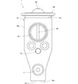
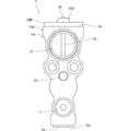
- FIG. 1 is a front view of an expansion valve according to a first embodiment of the present invention.
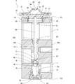
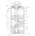
- FIG. 2 is a longitudinal sectional view of the expansion valve of FIG.
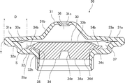
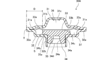
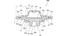
- FIG. 3 is a cross-sectional view of a power element included in the expansion valve of FIG. 4 is a cross-sectional view showing a configuration of a modification of the power element of FIG.
- “upper and lower” means upper and lower in each figure.
- the expansion valve 1 includes a valve body 10, a power element 30, a valve member 40, a support member 45, a coil spring 50, an adjustment screw 55, It has a valve stem 60 and a vibration isolation member 65.
- the valve main body 10 is obtained, for example, by subjecting a substantially quadrangular prism-shaped extruded body formed by extruding aluminum (or aluminum alloy) in a direction orthogonal to the paper surface of FIG.
- the valve body 10 is provided with a first refrigerant flow path 11, a second refrigerant flow path 12, a power element attachment portion 20, and an adjustment screw attachment portion 22.
- the first refrigerant flow path 11 has an inlet port 13, a valve chamber 14, a valve hole 15 and an outlet port 16. These are in sequence.
- the inlet port 13 is open to the front surface 10 a of the valve body 10.
- the inlet port 13 communicates with the valve chamber 14 from the side through a small diameter hole 13a.
- the outlet port 16 opens on the rear surface 10 b of the valve body 10.
- the outlet port 16 communicates with the valve chamber 14 from above via a valve hole 15 serving as an orifice.
- a valve seat 17 is provided at the valve chamber side opening of the valve hole 15.
- the second refrigerant channel 12 is provided above the first refrigerant channel 11.
- the second refrigerant channel 12 has an inlet provided on the rear surface 10b of the valve body 10 and an outlet provided on the front surface 10a.
- the second refrigerant channel 12 passes through the valve body 10 linearly from the rear surface 10b to the front surface 10a.
- valve body 10 is provided with a through hole 18 extending vertically.
- the valve chamber 14, the valve hole 15, the through hole 18, and the pressure equalizing hole 21 to be described later are arranged so that their central axes are on the same straight line.
- a large-diameter portion 18a is provided at the end of the through hole 18 on the second refrigerant channel 12 side.
- the power element mounting portion 20 is a cylindrical hole provided in the upper surface 10c of the valve body 10. An internal thread is cut on the inner peripheral surface of the power element mounting portion 20. A pressure equalizing hole 21 communicating with the second refrigerant channel 12 is provided on the bottom surface of the power element mounting portion 20.
- the central axis direction (up and down direction in FIG. 2) of the power element mounting portion 20 is orthogonal to the direction (left and right direction in FIG. 2) in which the second refrigerant flow path 12 extends.
- the adjustment screw mounting portion 22 is a circular hole provided in the lower surface 10d of the valve body 10.
- the adjusting screw mounting portion 22 communicates with the valve chamber 14.
- a female screw is cut on the inner peripheral surface of the adjustment screw mounting portion 22.
- the valve chamber 14 is closed with respect to the outside by closing the opening of the adjustment screw mounting portion 22 with an adjustment screw 55 described later.
- the front surface 10a of the valve body 10 is provided with a mounting hole 23 for mounting to an evaporator, other parts (not shown) or the like.
- An internal thread may be cut on the inner peripheral surface of the mounting hole 23.
- the power element 30 includes an upper lid member 31, a receiving member 32, a diaphragm 33, and a stopper member 34.
- the upper lid member 31, the receiving member 32, and the diaphragm 33 are made of a metal such as stainless steel, for example.
- the stopper member 34 is made of, for example, a resin such as polyphenylene sulfide (PPS), syndiotactic polystyrene (SPS), or polyamideimide (PAI).
- PPS polyphenylene sulfide
- SPS syndiotactic polystyrene
- PAI polyamideimide
- the upper lid member 31 has an annular outer peripheral part 31a and a substantially conical inner part 31b connected to the inner peripheral edge of the outer peripheral part 31a.
- a working gas injection hole 31c is provided at the center of the inner portion 31b.
- the receiving member 32 has an annular outer peripheral portion 32a having a stepped portion provided with a through hole 35 in the central portion, and extends downward connected to the inner peripheral edge of the outer peripheral portion 32a (the peripheral edge portion 35a of the through hole 35). And a cylindrical portion 32b. A male thread that engages with a female thread of the power element mounting portion 20 is cut on the outer peripheral surface of the cylindrical portion 32b.
- the diaphragm 33 has an annular outer peripheral portion 33a having a corrugated cross section and a circular flat plate-shaped central portion 33b connected to the inner peripheral edge of the outer peripheral portion 33a.
- the diaphragm 33 is sandwiched between the upper lid member 31 and the receiving member 32.
- the outer peripheral portion 31 a of the upper lid member 31 is superimposed on the upper surface (one surface) of the outer peripheral portion 33 a of the diaphragm 33, and the outer peripheral portion 32 a of the receiving member 32 is the lower surface (other surface) of the outer peripheral portion 33 a of the diaphragm 33. Is superimposed on. In a state where these are overlapped, the outer peripheral portion 31a of the upper lid member 31, the outer peripheral portion 32a of the receiving member 32, and the outer peripheral portion 33a of the diaphragm 33 are welded (circular welding) over the entire circumference.
- the upper lid member 31, the receiving member 32, and the diaphragm 33 are integrated by welding.
- TIG TUNGSTEN INERT GAS
- the upper lid member 31 forms a pressure working chamber 36 with the diaphragm 33.
- Working gas is injected into the pressure working chamber 36 from the working gas injection hole 31c.
- the working gas injection hole 31c is closed by the sealing plug 38 after the working gas is injected.
- the receiving member 32 forms a refrigerant inflow chamber 37 between the receiving member 32 and the diaphragm 33.
- the stopper member 34 includes a cylindrical portion 34a having a slightly smaller diameter than the through hole 35 and an annular flange portion 34b having a larger diameter than the through hole 35 provided at the upper end portion of the cylindrical portion 34a.
- the column portion 34 a is inserted into the cylindrical portion 32 b of the receiving member 32, and the flange portion 34 b is accommodated in the refrigerant inflow chamber 37.
- the flange portion 34 b is in contact with the peripheral edge portion 35 a of the through hole 35 of the receiving member 32, thereby preventing the stopper member 34 from falling off the through hole 35.
- the outer cover portions 31a, 32a, and 33a are welded so that the upper lid member 31, the receiving member 32, and the diaphragm 33 are integrated.
- connects the receiving member 32 in the flange part 34b, and the outer peripheral end T of outer peripheral part 31a, 32a, 33a is 6 mm or more.
- the upper surface 34 c of the stopper member 34 is disposed to face the central portion 33 b of the diaphragm 33.
- the lower surface 34d of the stopper member 34 is provided with a hole-shaped receiving portion 34e into which an upper end portion 61 (the other end portion) of a valve rod 60 described later is inserted.
- the stopper member 34 when the pressure in the pressure working chamber 36 and the pressure in the refrigerant inflow chamber 37 are equal, such as before the working gas injection hole 31c is closed with the sealing plug 38, there is a gap between the diaphragm 33 and the stopper member 34. It is configured to occur. By doing so, it is possible to prevent the heat of welding from being transmitted to the stopper member 34 through the diaphragm 33. Moreover, in the structure without the said clearance gap, the stopper member 34 is pressed against the receiving member 32 by the diaphragm 33, and there exists a possibility that it may receive the influence of the heat of the receiving member 32 more strongly. Therefore, by providing the gap, the deformation of the stopper member 34 due to the heat of welding can be more effectively suppressed.
- the male screw of the receiving member 32 is screwed with the female screw of the power element mounting portion 20. That is, the power element 30 is attached to the valve body 10 by a screw structure.
- the power element 30 is attached to the valve body 10 in a state where an annular seal member 39 is compressed and sandwiched between the receiving member 32 and the valve body 10.
- the second refrigerant flow path 12 and the refrigerant inflow chamber 37 communicate with each other through the pressure equalizing hole 21.
- the valve member 40 is a spherical member disposed in the valve chamber 14.
- the support member 45 supports the valve member 40 so as to face the valve seat 17.
- the valve member 40 may be fixed to the support member 45.
- the coil spring 50 is installed in a compressed state between the support member 45 and the adjusting screw 55.
- the coil spring 50 presses the valve member 40 toward the valve seat 17 via the support member 45.
- the adjustment screw 55 is screwed into the adjustment screw mounting portion 22 of the valve body 10. By adjusting the screwing amount of the adjusting screw 55, the elastic force (pressing force) of the coil spring 50 can be adjusted.
- valve rod 60 is inserted into each of the valve hole 15, the through hole 18, and the pressure equalizing hole 21 of the valve body 10.
- a lower end portion 62 (one end portion) of the valve rod 60 is in contact with the valve member 40 and is disposed so as to face the coil spring 50 through the valve member 40 and the support member 45.
- the upper end portion 61 of the valve stem 60 is inserted into the receiving portion 34 e of the stopper member 34 of the power element 30. Accordingly, the valve member 40 is driven by the power element 30 via the valve rod 60.
- the anti-vibration member 65 is disposed in the large diameter portion 18 a of the through hole 18.
- the anti-vibration member 65 is comprised of a plurality of leaf spring-like members, for example, and presses the valve stem 60 from the periphery. Thereby, the vibration of the valve stem 60 and the valve member 40 is prevented.
- the refrigerant flows into the inlet port 13, passes through the valve chamber 14 and the valve hole 15, is expanded, flows out from the outlet port 16, and is sent to an evaporator (not shown).
- the refrigerant that has passed through the evaporator passes through the second refrigerant flow path 12 from the inlet to the outlet, and returns to the compressor (not shown).
- a part of the refrigerant passing through the second refrigerant flow path 12 flows into the refrigerant inflow chamber 37 of the power element 30 from the pressure equalizing hole 21.
- the pressure in the pressure working chamber 36 changes according to the temperature change of the refrigerant flowing into the refrigerant inflow chamber 37.
- the stopper member 34 moves up and down. Then, the movement of the stopper member 34 is transmitted to the valve member 40 via the valve rod 60. Thereby, the expansion valve 1 automatically adjusts the flow rate according to the temperature of the refrigerant.
- the outer cover portions 31a, 32a, and 33a are welded so that the upper cover member 31, the receiving member 32, and the diaphragm 33 of the power element 30 are integrated.
- the resin stopper member 34 is accommodated in a refrigerant inflow chamber 37 formed between the diaphragm 33 and the receiving member 32, and is formed in a peripheral portion 35 a of the through hole 35 provided in the central portion of the receiving member 32. It has a flange portion 34b in contact therewith. And the distance D of the radial direction of the part S which contact
- the portion S in contact with the receiving member 32 in the flange portion 34b and the outer peripheral ends T of the outer peripheral portions 31a, 32a, 33a As shown in FIG. 4, also in the power element 30A in which the above-described power element 30 is downsized as a whole, the portion S in contact with the receiving member 32 in the flange portion 34b and the outer peripheral ends T of the outer peripheral portions 31a, 32a, 33a.
- the distance D in the radial direction is 6 mm or more, the deformation of the stopper member 34 due to the heat of welding at the time of manufacturing the power element can be suppressed.
- the power element is attached to the valve body by a caulking structure.
- FIG. 5 is a front view of the expansion valve according to the second embodiment of the present invention.
- 6 is a longitudinal sectional view of the expansion valve of FIG.
- FIG. 7 is a cross-sectional view of a power element included in the expansion valve of FIG.
- “up and down” refers to the upper and lower sides in each figure.
- members and the like having the same functions as those of the first embodiment are denoted by the same reference numerals as those of the first embodiment, and description thereof is omitted.
- the expansion valve 2 includes a valve main body 10 ⁇ / b> B, a power element 30 ⁇ / b> B, a valve member 40, a support member 45, a coil spring 50, and an adjustment screw 55.
- the valve stem 60 and the vibration isolation member 65 are provided.
- the valve body 10B is the first except that it has a power element mounting portion 20B having a caulking structure in place of the power element mounting portion 20 formed of a cylindrical hole portion having a female thread on the inner peripheral surface. It has the same configuration as the valve body 10 of the embodiment.
- the power element mounting portion 20B is integrally provided on the upper surface 10c of the valve body 10B.
- the power element mounting portion 20B has a cylindrical shape before the power element 30B is mounted. After the power element 30B is accommodated inside, the tip portion facing upward is bent inward to By tightening, the power element 30B is attached to the valve body 10B.
- the radial distance D between the portion S in contact with the receiving member 32 in the flange portion 34b and the outer peripheral end T of the outer peripheral portions 31a, 32a, 33a is 6 mm or more. . Therefore, the deformation of the stopper member 34 due to the heat of welding at the time of manufacturing the power element can be suppressed.
Landscapes
- Engineering & Computer Science (AREA)
- Physics & Mathematics (AREA)
- General Engineering & Computer Science (AREA)
- Mechanical Engineering (AREA)
- Fluid Mechanics (AREA)
- Thermal Sciences (AREA)
- Temperature-Responsive Valves (AREA)
- Check Valves (AREA)
- Air-Conditioning For Vehicles (AREA)
Abstract
【課題】溶接の熱による樹脂製のストッパ部材の変形を抑制できるパワーエレメント、および、このパワーエレメントを有する膨張弁を提供する。 【解決手段】膨張弁1において、パワーエレメント30の上蓋部材31、受け部材32およびダイアフラム33は、一体となるように外周部31a、32a、33aが溶接されている。樹脂製のストッパ部材34は、ダイアフラム33と受け部材32との間に形成された冷媒流入室37に収容されているとともに、受け部材32の中央部に設けられた貫通孔35の周縁部35aに接するフランジ部34bを有している。そして、フランジ部34bにおける受け部材32と接する部分Sと外周部31a、32a、33aの外周端Tとの径方向の距離Dが6mm以上である。
Description
本発明は、冷凍サイクルに用いられる感温機構内蔵型の膨張弁、および、この膨張弁が有するパワーエレメントに関する。
従来、自動車に搭載される空調装置等の冷凍サイクルにおいて、冷媒の通過量を温度に応じて調整する感温機構内蔵型の膨張弁が用いられている(例えば、特許文献1および特許文献2参照)。
このような膨張弁は、弁本体と、弁本体に取り付けられた弁部材駆動装置であるパワーエレメントと、を有している。弁本体には、入口ポート、弁室、弁孔および出口ポートが順に連なって構成された、高圧の冷媒が流れる第1の冷媒流路が設けられている。また、弁本体には、パワーエレメントに通じる第2の冷媒流路が設けられている。弁室には、球状の弁部材が配置されている。この弁部材は、コイルばねによって、弁孔の弁室側開口部に設けられた弁座に向けて押圧されている。また、弁孔には、弁棒が挿通されている。この弁棒は、一方の端部が弁部材を介してコイルばねと対向しており、他方の端部がパワーエレメントに取り付けられている。
パワーエレメントは、上蓋部材と受け部材との間に、圧力を受けて弾性変形する薄板のダイアフラムを挟んで構成されている。上蓋部材とダイアフラムとの間には圧力作動室が形成されている。ダイアフラムと受け部材との間には金属製のストッパ部材が配置されている。ストッパ部材は、弁棒の他方の端部が当接される受け部が設けられている。パワーエレメントは、第2の冷媒流路を流れる冷媒の熱がストッパ部材およびダイアフラムを介して圧力作動室に伝わると、圧力作動室に充填されたガスが膨張する。これにより、ダイアフラムがストッパ部材側に膨らむように変形し、ストッパ部材および弁棒を介して弁部材を駆動して、弁部材と弁座との間の開度を制御する。
膨張弁は、自動車に搭載する際のスペースおよび重量の制約から小型化が求められている。膨張弁を小型化すると、第2の冷媒流路とパワーエレメントとが近づくので、圧力作動室に冷媒の熱が伝わりやすくなり、パワーエレメントにおいて冷媒の温度変化に対する感度が高まる。これにより、冷媒の流量が短い周期で変動を繰り返すいわゆるハンチング現象が生じるおそれがある。このようなハンチング現象は、熱伝導率の低い樹脂製のストッパ部材を採用して冷媒の温度変化に対する感度を適正化することで抑制できる。
ところで、パワーエレメントの受け部材は中央部に貫通孔が設けられており、ストッパ部材のフランジ部がこの貫通孔の周縁部に接することで、ストッパ部材の脱落を防いでいる。樹脂製のストッパ部材は、脱落を確実に防ぐためにフランジ部をより外側に広げることが望まれる。しかしながら、パワーエレメントは、上蓋部材とダイアフラムと受け部材とを重ね合わせてこれらが一体となるように外周部を溶接により接合している。そのため、ストッパ部材が溶接時の熱の影響を受けて変形してしまうおそれがある。
そこで、本発明の目的は、溶接の熱による樹脂製のストッパ部材の変形を抑制できるパワーエレメント、および、このパワーエレメントを有する膨張弁を提供することにある。
本発明者らは、溶接時の熱が主に受け部材を通じてストッパ部材に伝わることに着目し、受け部材の形状や厚さなどの異なるパワーエレメントを多数作製し、シミュレーションを併用しながら、溶接時の熱がストッパ部材に与える影響について鋭意検討を重ねた。その結果、受け部材の形状や厚さなどにかかわらず、上記影響を効果的に抑制できる構成を見いだし、本発明に至った。
上記目的を達成するため、本発明の一態様に係るパワーエレメントは、ダイアフラムと、前記ダイアフラムの一方の面に重ねられ、前記ダイアフラムとの間に圧力作動室を形成する上蓋部材と、前記ダイアフラムの他方の面に重ねられ、前記ダイアフラムとの間に冷媒流入室を形成する受け部材と、前記冷媒流入室に収容された樹脂製のストッパ部材と、を有し、前記受け部材の中央部に貫通孔が設けられ、前記ストッパ部材は、前記受け部材の前記貫通孔の周縁部に接するフランジ部を有し、前記上蓋部材、前記受け部材および前記ダイアフラムは、一体となるように外周部が溶接されており、前記フランジ部における前記受け部材と接する部分と前記外周部の外周端との径方向の距離が6mm以上であることを特徴とする。
本発明において、前記圧力作動室の圧力と前記冷媒流入室の圧力とが等しいとき、前記ダイアフラムと前記ストッパ部材との間に隙間が生じるように構成されていることが好ましい。
上記目的を達成するため、本発明の他の一態様に係る膨張弁は、弁室および弁孔を有する冷媒流路が設けられた弁本体と、前記弁室に配置された弁部材と、前記弁部材を前記弁孔の弁室側開口部に向けて押圧するコイルばねと、前記弁孔に挿通され、前記弁部材を介して前記コイルばねと対向するように配置された弁棒と、前記弁棒を介して前記弁部材を駆動するパワーエレメントと、を有し、前記パワーエレメントが、上記パワーエレメントで構成されていることを特徴とする。
本発明によれば、上蓋部材、受け部材およびダイアフラムは、一体となるように外周部が溶接されている。樹脂製のストッパ部材は、ダイアフラムと受け部材との間に形成された冷媒流入室に収容されているとともに、受け部材の中央部に設けられた貫通孔の周縁部に接するフランジ部を有している。そして、フランジ部における受け部材と接する部分と外周部の外周端との径方向の距離が6mm以上である。このようにしたことから、受け部材を通じてストッパ部材に伝わる溶接の熱を小さくして、溶接の熱によるストッパ部材の変形を抑制できる。
(第1実施例)
以下に、本発明の第1実施例に係る膨張弁について、図1~図4を参照して説明する。第1実施例に係る膨張弁は、パワーエレメントをねじ構造により弁本体に取り付けるものである。
以下に、本発明の第1実施例に係る膨張弁について、図1~図4を参照して説明する。第1実施例に係る膨張弁は、パワーエレメントをねじ構造により弁本体に取り付けるものである。
図1は、本発明の第1実施例に係る膨張弁の正面図である。図2は、図1の膨張弁の縦断面図である。図3は、図1の膨張弁が有するパワーエレメントの断面図である。図4は、図3のパワーエレメントの変形例の構成を示す断面図である。以下の説明において、「上下」とは、各図における上下のことを指す。
図1および図2に示すように、第1実施例に係る膨張弁1は、弁本体10と、パワーエレメント30、弁部材40と、支持部材45と、コイルばね50と、調整ねじ55と、弁棒60と、防振部材65と、を有している。
弁本体10は、例えば、図1の紙面と直交する方向にアルミニウム(またはアルミニウム合金)を押し出すことにより成形された略四角柱状の押出成形体に対して、機械加工を施すことによって得られる。弁本体10は、第1の冷媒流路11と、第2の冷媒流路12と、パワーエレメント取付部20と、調整ねじ取付部22と、が設けられている。
第1の冷媒流路11は、入口ポート13、弁室14、弁孔15および出口ポート16を有している。これらは順に連なっている。入口ポート13は、弁本体10の前面10aに開口している。入口ポート13は、小径孔13aを介して弁室14に側方から通じている。出口ポート16は、弁本体10の後面10bに開口している。出口ポート16は、オリフィスとなる弁孔15を介して弁室14に上方から通じている。弁孔15の弁室側開口部には弁座17が設けられている。
第2の冷媒流路12は、第1の冷媒流路11の上方に設けられている。第2の冷媒流路12は、弁本体10の後面10bに入口が設けられ、前面10aに出口が設けられている。第2の冷媒流路12は、弁本体10を後面10bから前面10aまで直線状に貫通している。
また、弁本体10には、上下に延びる通し孔18が設けられている。弁室14、弁孔15、通し孔18および後述する均圧孔21は、それぞれの中心軸が同一直線上になるように配置されている。通し孔18の第2の冷媒流路12側の端部には大径部18aが設けられている。
パワーエレメント取付部20は、弁本体10の上面10cに設けられた円柱状の穴部である。パワーエレメント取付部20の内周面には雌ねじが切られている。パワーエレメント取付部20の底面には、第2の冷媒流路12に通じる均圧孔21が設けられている。パワーエレメント取付部20の中心軸方向(図2の上下方向)は、第2の冷媒流路12が延びる方向(図2の左右方向)と直交している。
調整ねじ取付部22は、弁本体10の下面10dに設けられた円形孔である。調整ねじ取付部22は、弁室14と通じている。調整ねじ取付部22の内周面には雌ねじが切られている。調整ねじ取付部22の開口部分を後述する調整ねじ55で塞ぐことにより、弁室14が外部に対して閉じられる。
弁本体10の前面10aには、図示しない蒸発器や他の部品等に取り付けるための取付穴23が設けられている。取付穴23の内周面に雌ねじが切られていてもよい。
図3に示すように、パワーエレメント30は、上蓋部材31と、受け部材32と、ダイアフラム33と、ストッパ部材34と、を有している。上蓋部材31、受け部材32およびダイアフラム33は、例えば、ステンレス鋼などの金属を材料として構成されている。ストッパ部材34は、例えば、ポリフェニレンサルファイド(PPS)、シンジオタクチックポリスチレン(SPS)またはポリアミドイミド(PAI)などの樹脂を材料として構成されている。パワーエレメント30の各部材は、本発明の目的に反しない限り、これら以外の材料で構成されていてもよい。
上蓋部材31は、円環状の外周部31aと、外周部31aの内周縁に連接された略円錐形状の内側部31bと、を有している。内側部31bの中央部には作動ガス注入孔31cが設けられている。
受け部材32は、中央部に貫通孔35が設けられた、段部を有する円環状の外周部32aと、外周部32aの内周縁(貫通孔35の周縁部35a)に連接された下方に延びる円筒部32bと、を有している。円筒部32bの外周面には、パワーエレメント取付部20の雌ねじに螺合する雄ねじが切られている。
ダイアフラム33は、波形の断面を有する円環状の外周部33aと、外周部33aの内周縁に連接された円形平板状の中央部33bと、を有している。ダイアフラム33は、上蓋部材31および受け部材32で挟まれている。
上蓋部材31は、その外周部31aがダイアフラム33の外周部33aの上面(一方の面)に重ねられ、受け部材32は、その外周部32aがダイアフラム33の外周部33aの下面(他方の面)に重ねられる。これらを重ね合わせた状態で、上蓋部材31の外周部31a、受け部材32の外周部32aおよびダイアフラム33の外周部33aが全周にわたって溶接(周溶接)されている。溶接により、上蓋部材31、受け部材32およびダイアフラム33が一体化されている。溶接方法としては、局所的な加工に適したTIG(TUNGSTEN INERT GAS)溶接、またはレーザー溶接が好ましい。
上蓋部材31は、ダイアフラム33との間に圧力作動室36を形成している。圧力作動室36には、作動ガス注入孔31cから作動ガスが注入される。作動ガス注入孔31cは、作動ガス注入後に封止栓38により塞がれる。受け部材32は、ダイアフラム33との間に冷媒流入室37を形成している。
ストッパ部材34は、貫通孔35より若干小径の円柱部34aと、円柱部34aの上端部に設けられた、貫通孔35より大径の円環状のフランジ部34bと、を有している。ストッパ部材34は、円柱部34aが受け部材32の円筒部32bに挿通され、フランジ部34bが冷媒流入室37に収容される。
フランジ部34bは、受け部材32の貫通孔35の周縁部35aに接しており、これにより、ストッパ部材34が貫通孔35からの脱落することを防いでいる。
本実施例において、上蓋部材31、受け部材32およびダイアフラム33は、一体となるように外周部31a、32a、33aが溶接されている。そして、フランジ部34bにおける受け部材32と接する部分Sと外周部31a、32a、33aの外周端Tとの径方向の距離Dが6mm以上である。本発明者らは、多数の試作品を用いて確認した結果、この距離Dを6mm以上にすることで、パワーエレメント作製時の溶接の熱によるストッパ部材34の変形を抑制できることをつきとめた。
ストッパ部材34の上面34cは、ダイアフラム33の中央部33bと対向して配置される。圧力作動室36の圧力が高まるとダイアフラム33が膨らみ、中央部33bによってストッパ部材34の上面34cが下方に押される。ストッパ部材34の下面34dには、後述する弁棒60の上端部61(他方の端部)が挿入される穴状の受け部34eが設けられている。
本実施例において、作動ガス注入孔31cを封止栓38で塞ぐ前など、圧力作動室36の圧力と冷媒流入室37の圧力とが等しいとき、ダイアフラム33とストッパ部材34との間に隙間が生じるように構成されている。このようにすることで、溶接の熱がダイアフラム33を通じてストッパ部材34に伝わることを防止することができる。また、上記隙間のない構成では、ダイアフラム33によってストッパ部材34が受け部材32に押しつけられ、受け部材32の熱の影響をより強く受けてしまうおそれがある。そのため、上記隙間を設けることで、溶接の熱によるストッパ部材34の変形をより効果的に抑制できる。
パワーエレメント30は、受け部材32の雄ねじがパワーエレメント取付部20の雌ねじと螺合される。すなわち、弁本体10にネジ構造によってパワーエレメント30が取り付けられている。パワーエレメント30は、受け部材32と弁本体10との間に円環状のシール部材39を圧縮して挟み込んだ状態で弁本体10に取り付けられる。パワーエレメント30は、パワーエレメント取付部20に取り付けられると、均圧孔21を介して第2の冷媒流路12と冷媒流入室37とが通じる。
弁部材40は、弁室14に配置された球状の部材である。
支持部材45は、弁部材40を弁座17に対向するように支持する。弁部材40が支持部材45に固定された構成でもよい。
コイルばね50は、支持部材45と調整ねじ55との間に圧縮状態で設置されている。コイルばね50は、支持部材45を介して弁部材40を弁座17に向けて押圧している。
調整ねじ55は、弁本体10の調整ねじ取付部22に螺合されている。調整ねじ55のねじ込み量を調整することにより、コイルばね50の弾性力(押圧力)を調整できる。
弁棒60は、弁本体10の弁孔15、通し孔18および均圧孔21のそれぞれに挿通されている。弁棒60の下端部62(一方の端部)は、弁部材40に接しており、弁部材40および支持部材45を介してコイルばね50と対向するように配置されている。弁棒60の上端部61は、パワーエレメント30のストッパ部材34の受け部34eに挿入される。これにより、パワーエレメント30によって、弁棒60を介して弁部材40が駆動される。
防振部材65は、通し孔18の大径部18aに配置されている。防振部材65は、例えば、複数の板ばね状の部材で構成され、弁棒60を周囲から押圧する。これにより、弁棒60及び弁部材40の振動を防止する。
次に、膨張弁1の動作について説明する。膨張弁1は、冷媒が入口ポート13に流入し、弁室14及び弁孔15を通過して膨張され、出口ポート16から流出して蒸発器(図示せず)へ送り出される。また、この蒸発器を通過した冷媒は、第2の冷媒流路12の入口から出口に抜けるように通過し、圧縮機(図示せず)へ戻る。このとき、第2の冷媒流路12を通過する冷媒の一部は均圧孔21からパワーエレメント30の冷媒流入室37に流入する。そして冷媒流入室37に流入した冷媒の温度変化に応じて圧力作動室36の圧力が変化する。圧力作動室36の圧力に応じて変形したダイアフラム33の動きを受け、ストッパ部材34が上下に移動する。そして、ストッパ部材34の移動が弁棒60を介して弁部材40に伝達される。これにより、膨張弁1は、冷媒の温度に応じて流量を自動的に調整する。
以上より、膨張弁1によれば、パワーエレメント30の上蓋部材31、受け部材32およびダイアフラム33は、一体となるように外周部31a、32a、33aが溶接されている。樹脂製のストッパ部材34は、ダイアフラム33と受け部材32との間に形成された冷媒流入室37に収容されているとともに、受け部材32の中央部に設けられた貫通孔35の周縁部35aに接するフランジ部34bを有している。そして、フランジ部34bにおける受け部材32と接する部分Sと外周部31a、32a、33aの外周端Tとの径方向の距離Dが6mm以上である。このようにしたことから、受け部材32を通じてストッパ部材34に伝わる溶接の熱を小さくして、溶接の熱によるストッパ部材34の変形を抑制できる。
なお、図4に示すように、上述したパワーエレメント30を全体的に小型化したパワーエレメント30Aにおいても、フランジ部34bにおける受け部材32と接する部分Sと外周部31a、32a、33aの外周端Tとの径方向の距離Dを6mm以上にすることで、パワーエレメント作製時の溶接の熱によるストッパ部材34の変形を抑制することができる。
(第2実施例)
以下に、本発明の第2実施例に係る膨張弁について、図5~図7を参照して説明する。第2実施例に係る膨張弁は、パワーエレメントをカシメ構造により弁本体に取り付けるものである。
以下に、本発明の第2実施例に係る膨張弁について、図5~図7を参照して説明する。第2実施例に係る膨張弁は、パワーエレメントをカシメ構造により弁本体に取り付けるものである。
図5は、本発明の第2実施例に係る膨張弁の正面図である。図6は、図5の膨張弁の縦断面図である。図7は、図5の膨張弁が有するパワーエレメントの断面図である。以下の説明においても、「上下」とは、各図における上下のことを指す。また、第1実施例と同等の機能を有する部材等については、第1実施例と同一の符号を付して説明を省略する。
図5および図6に示すように、第2実施例に係る膨張弁2は、弁本体10Bと、パワーエレメント30Bと、弁部材40と、支持部材45と、コイルばね50と、調整ねじ55と、弁棒60と、防振部材65と、を有している。
弁本体10Bは、内周面に雌ねじが切られた円柱状の穴部からなるパワーエレメント取付部20に代えて、カシメ構造を有するパワーエレメント取付部20Bを有していること以外は、第1実施例の弁本体10と同等の構成を有している。
パワーエレメント取付部20Bは、弁本体10Bの上面10cに一体に設けられている。パワーエレメント取付部20Bは、パワーエレメント30Bを取り付ける前は円筒形状を有し、パワーエレメント30Bが内側に収容された後、上方を向く先端部を内側に折り曲げて、パワーエレメント30Bの外周部にかしめることにより、パワーエレメント30Bを弁本体10Bに取り付ける。
パワーエレメント30Bは、外周部32aおよび円筒部32bを有する受け部材32に代えて、段部を有する外周部32aのみ有する受け部材32Bを有していること以外は、第1実施例のパワーエレメント30と同等の構成を有している。
このパワーエレメント30Bにおいても、第1実施例と同様に、フランジ部34bにおける受け部材32と接する部分Sと外周部31a、32a、33aの外周端Tとの径方向の距離Dが6mm以上である。そのため、パワーエレメント作製時の溶接の熱によるストッパ部材34の変形を抑制することができる。
上記に本発明の実施例を説明したが、本発明はこれらの例に限定されない。前述の実施例に対して、当業者が適宜、構成要素の追加、削除、設計変更を行ったものや、実施例の特徴を適宜組み合わせたものも、本発明の趣旨を逸脱しない限り、本発明の範囲に含まれる。
1、2…膨張弁、10、10B…弁本体、10a…前面、10b…後面、10c…上面、10d…下面、11…第1の冷媒流路、12…第2の冷媒流路、13…入口ポート、14…弁室、15…弁孔、16…出口ポート、17…弁座、18…通し孔、18a…大径部、20、20B…パワーエレメント取付部、21…均圧孔、22…調整ねじ取付部、23…取付穴、30、30A、30B…パワーエレメント、31…上蓋部材、31a…外周部、31b…内側部、31c…作動ガス注入孔、32、32B…受け部材、32a…外周部、32b…円筒部、33…ダイアフラム、33a…外周部、33b…中央部、34…ストッパ部材、34a…円柱部、34b…フランジ部、34c…上面、34d…下面、34e…受け部、35…貫通孔、35a…周縁部、36…圧力作動室、37…冷媒流入室、38…封止栓、39…シール部材、40…弁部材、45…支持部材、50…コイルばね、55…調整ねじ、60…弁棒、61…上端部、62…下端部、65…防振部材、S…フランジ部における受け部材に接する部分、T…外周端、D…距離
Claims (3)
- ダイアフラムと、
前記ダイアフラムの一方の面に重ねられ、前記ダイアフラムとの間に圧力作動室を形成する上蓋部材と、
前記ダイアフラムの他方の面に重ねられ、前記ダイアフラムとの間に冷媒流入室を形成する受け部材と、
前記冷媒流入室に収容された樹脂製のストッパ部材と、を有し、
前記受け部材の中央部に貫通孔が設けられ、
前記ストッパ部材は、前記受け部材の前記貫通孔の周縁部に接するフランジ部を有し、
前記上蓋部材、前記受け部材および前記ダイアフラムは、一体となるように外周部が溶接されており、
前記フランジ部における前記受け部材と接する部分と前記外周部の外周端との径方向の距離が6mm以上であることを特徴とするパワーエレメント。 - 前記圧力作動室の圧力と前記冷媒流入室の圧力とが等しいとき、前記ダイアフラムと前記ストッパ部材との間に隙間が生じるように構成されていることを特徴とする請求項1に記載のパワーエレメント。
- 弁室および弁孔を有する冷媒流路が設けられた弁本体と、
前記弁室に配置された弁部材と、
前記弁部材を前記弁孔の弁室側開口部に向けて押圧するコイルばねと、
前記弁孔に挿通され、前記弁部材を介して前記コイルばねと対向するように配置された弁棒と、
前記弁棒を介して前記弁部材を駆動するパワーエレメントと、を有し、
前記パワーエレメントが、請求項1または請求項2に記載のパワーエレメントで構成されていることを特徴とする膨張弁。
Priority Applications (2)
| Application Number | Priority Date | Filing Date | Title |
|---|---|---|---|
| CN201980012940.3A CN111868461B (zh) | 2018-03-20 | 2019-02-27 | 动力元件以及具有该动力元件的膨胀阀 |
| EP19770738.3A EP3770536A4 (en) | 2018-03-20 | 2019-02-27 | POWER ELEMENT AND EXPANSION VALVE WITH IT |
Applications Claiming Priority (2)
| Application Number | Priority Date | Filing Date | Title |
|---|---|---|---|
| JP2018-051857 | 2018-03-20 | ||
| JP2018051857A JP6961232B2 (ja) | 2018-03-20 | 2018-03-20 | パワーエレメントおよびそれを有する膨張弁 |
Publications (1)
| Publication Number | Publication Date |
|---|---|
| WO2019181409A1 true WO2019181409A1 (ja) | 2019-09-26 |
Family
ID=67987725
Family Applications (1)
| Application Number | Title | Priority Date | Filing Date |
|---|---|---|---|
| PCT/JP2019/007620 Ceased WO2019181409A1 (ja) | 2018-03-20 | 2019-02-27 | パワーエレメントおよびそれを有する膨張弁 |
Country Status (4)
| Country | Link |
|---|---|
| EP (1) | EP3770536A4 (ja) |
| JP (1) | JP6961232B2 (ja) |
| CN (1) | CN111868461B (ja) |
| WO (1) | WO2019181409A1 (ja) |
Cited By (2)
| Publication number | Priority date | Publication date | Assignee | Title |
|---|---|---|---|---|
| EP4067714A4 (en) * | 2019-11-25 | 2023-11-22 | Fujikoki Corporation | Power element and expansion valve using same |
| EP4067715A4 (en) * | 2019-11-25 | 2024-02-07 | Fujikoki Corporation | Power element and expansion valve using same |
Families Citing this family (2)
| Publication number | Priority date | Publication date | Assignee | Title |
|---|---|---|---|---|
| JP7366401B2 (ja) * | 2019-11-25 | 2023-10-23 | 株式会社不二工機 | パワーエレメント及びこれを用いた膨張弁 |
| CN114251461A (zh) * | 2020-09-22 | 2022-03-29 | 浙江三花汽车零部件有限公司 | 一种热力膨胀阀 |
Citations (4)
| Publication number | Priority date | Publication date | Assignee | Title |
|---|---|---|---|---|
| JPS51136B2 (ja) | 1972-11-14 | 1976-01-06 | ||
| CN102252469A (zh) * | 2010-05-20 | 2011-11-23 | 浙江三花汽车零部件有限公司 | 热力膨胀阀 |
| JP2016196982A (ja) | 2015-04-03 | 2016-11-24 | 株式会社不二工機 | カシメ固定型パワーエレメント及びこれを用いた膨張弁 |
| JP2018004234A (ja) * | 2016-07-08 | 2018-01-11 | 株式会社テージーケー | 膨張弁 |
Family Cites Families (6)
| Publication number | Priority date | Publication date | Assignee | Title |
|---|---|---|---|---|
| JP3207716B2 (ja) * | 1994-12-22 | 2001-09-10 | 株式会社不二工機 | 温度膨張弁 |
| JPH09178006A (ja) * | 1995-12-26 | 1997-07-11 | Fuji Koki:Kk | 温度膨張弁 |
| JP4081295B2 (ja) * | 2002-04-30 | 2008-04-23 | 株式会社不二工機 | 膨張弁 |
| CN100473881C (zh) * | 2005-12-02 | 2009-04-01 | 浙江三花制冷集团有限公司 | 热力膨胀阀 |
| CN101799077B (zh) * | 2009-07-05 | 2011-10-19 | 浙江三花股份有限公司 | 一种电磁阀 |
| CN102454823A (zh) * | 2010-10-16 | 2012-05-16 | 浙江三花股份有限公司 | 气箱头部件及其加工方法和使用该部件的热力膨胀阀 |
-
2018
- 2018-03-20 JP JP2018051857A patent/JP6961232B2/ja active Active
-
2019
- 2019-02-27 CN CN201980012940.3A patent/CN111868461B/zh active Active
- 2019-02-27 WO PCT/JP2019/007620 patent/WO2019181409A1/ja not_active Ceased
- 2019-02-27 EP EP19770738.3A patent/EP3770536A4/en not_active Withdrawn
Patent Citations (4)
| Publication number | Priority date | Publication date | Assignee | Title |
|---|---|---|---|---|
| JPS51136B2 (ja) | 1972-11-14 | 1976-01-06 | ||
| CN102252469A (zh) * | 2010-05-20 | 2011-11-23 | 浙江三花汽车零部件有限公司 | 热力膨胀阀 |
| JP2016196982A (ja) | 2015-04-03 | 2016-11-24 | 株式会社不二工機 | カシメ固定型パワーエレメント及びこれを用いた膨張弁 |
| JP2018004234A (ja) * | 2016-07-08 | 2018-01-11 | 株式会社テージーケー | 膨張弁 |
Non-Patent Citations (1)
| Title |
|---|
| See also references of EP3770536A4 |
Cited By (2)
| Publication number | Priority date | Publication date | Assignee | Title |
|---|---|---|---|---|
| EP4067714A4 (en) * | 2019-11-25 | 2023-11-22 | Fujikoki Corporation | Power element and expansion valve using same |
| EP4067715A4 (en) * | 2019-11-25 | 2024-02-07 | Fujikoki Corporation | Power element and expansion valve using same |
Also Published As
| Publication number | Publication date |
|---|---|
| JP6961232B2 (ja) | 2021-11-05 |
| EP3770536A1 (en) | 2021-01-27 |
| CN111868461A (zh) | 2020-10-30 |
| EP3770536A4 (en) | 2021-12-01 |
| CN111868461B (zh) | 2022-04-05 |
| JP2019163896A (ja) | 2019-09-26 |
Similar Documents
| Publication | Publication Date | Title |
|---|---|---|
| WO2019181409A1 (ja) | パワーエレメントおよびそれを有する膨張弁 | |
| US10436484B2 (en) | Caulking fixation type power element and expansion valve using the same | |
| CN100394126C (zh) | 膨胀阀 | |
| CN102762935B (zh) | 膨胀阀 | |
| EP2503267B1 (en) | Expansion valve | |
| JP6745636B2 (ja) | 膨張弁 | |
| JP2017198386A (ja) | 膨張弁 | |
| CN107615204A (zh) | 减压阀 | |
| JP7624762B2 (ja) | パワーエレメント及びこれを用いた膨張弁 | |
| EP4067715B1 (en) | Expansion valve comprising a power element | |
| JP2018115799A (ja) | 膨張弁 | |
| WO2018030115A1 (ja) | 膨張弁 | |
| JP2012197989A (ja) | 膨張弁 | |
| EP4067713A1 (en) | Power element and expansion valve using same | |
| JP2018004234A (ja) | 膨張弁 | |
| WO2017038271A1 (ja) | 絞り装置及び冷凍サイクル | |
| JP6788887B2 (ja) | 膨張弁 | |
| CN102252469B (zh) | 热力膨胀阀 | |
| JP7051091B2 (ja) | 膨張弁 | |
| JP7599211B2 (ja) | パワーエレメント及びそれを備えた膨張弁 | |
| JP7519664B2 (ja) | 膨張弁 | |
| JP7246075B2 (ja) | 膨張弁 | |
| JP7349706B2 (ja) | パワーエレメント及びこれを用いた膨張弁 | |
| JP2017058112A (ja) | 膨張弁 | |
| US10900530B2 (en) | Expansion valve |
Legal Events
| Date | Code | Title | Description |
|---|---|---|---|
| 121 | Ep: the epo has been informed by wipo that ep was designated in this application |
Ref document number: 19770738 Country of ref document: EP Kind code of ref document: A1 |
|
| NENP | Non-entry into the national phase |
Ref country code: DE |
|
| ENP | Entry into the national phase |
Ref document number: 2019770738 Country of ref document: EP Effective date: 20201020 |
|
| WWW | Wipo information: withdrawn in national office |
Ref document number: 2019770738 Country of ref document: EP |