WO2019181580A1 - Dispositif de filtration, dispositif de purification et procédé de production d'une solution chimique - Google Patents
Dispositif de filtration, dispositif de purification et procédé de production d'une solution chimique Download PDFInfo
- Publication number
- WO2019181580A1 WO2019181580A1 PCT/JP2019/009500 JP2019009500W WO2019181580A1 WO 2019181580 A1 WO2019181580 A1 WO 2019181580A1 JP 2019009500 W JP2019009500 W JP 2019009500W WO 2019181580 A1 WO2019181580 A1 WO 2019181580A1
- Authority
- WO
- WIPO (PCT)
- Prior art keywords
- filter
- filtration device
- liquid
- group
- purified
- Prior art date
- Legal status (The legal status is an assumption and is not a legal conclusion. Google has not performed a legal analysis and makes no representation as to the accuracy of the status listed.)
- Ceased
Links
Images










Classifications
-
- G—PHYSICS
- G03—PHOTOGRAPHY; CINEMATOGRAPHY; ANALOGOUS TECHNIQUES USING WAVES OTHER THAN OPTICAL WAVES; ELECTROGRAPHY; HOLOGRAPHY
- G03F—PHOTOMECHANICAL PRODUCTION OF TEXTURED OR PATTERNED SURFACES, e.g. FOR PRINTING, FOR PROCESSING OF SEMICONDUCTOR DEVICES; MATERIALS THEREFOR; ORIGINALS THEREFOR; APPARATUS SPECIALLY ADAPTED THEREFOR
- G03F7/00—Photomechanical, e.g. photolithographic, production of textured or patterned surfaces, e.g. printing surfaces; Materials therefor, e.g. comprising photoresists; Apparatus specially adapted therefor
- G03F7/16—Coating processes; Apparatus therefor
-
- B—PERFORMING OPERATIONS; TRANSPORTING
- B01—PHYSICAL OR CHEMICAL PROCESSES OR APPARATUS IN GENERAL
- B01D—SEPARATION
- B01D61/00—Processes of separation using semi-permeable membranes, e.g. dialysis, osmosis or ultrafiltration; Apparatus, accessories or auxiliary operations specially adapted therefor
- B01D61/58—Multistep processes
-
- B—PERFORMING OPERATIONS; TRANSPORTING
- B01—PHYSICAL OR CHEMICAL PROCESSES OR APPARATUS IN GENERAL
- B01D—SEPARATION
- B01D3/00—Distillation or related exchange processes in which liquids are contacted with gaseous media, e.g. stripping
- B01D3/14—Fractional distillation or use of a fractionation or rectification column
- B01D3/143—Fractional distillation or use of a fractionation or rectification column by two or more of a fractionation, separation or rectification step
- B01D3/145—One step being separation by permeation
-
- B—PERFORMING OPERATIONS; TRANSPORTING
- B01—PHYSICAL OR CHEMICAL PROCESSES OR APPARATUS IN GENERAL
- B01D—SEPARATION
- B01D61/00—Processes of separation using semi-permeable membranes, e.g. dialysis, osmosis or ultrafiltration; Apparatus, accessories or auxiliary operations specially adapted therefor
- B01D61/02—Reverse osmosis; Hyperfiltration ; Nanofiltration
- B01D61/027—Nanofiltration
-
- B—PERFORMING OPERATIONS; TRANSPORTING
- B01—PHYSICAL OR CHEMICAL PROCESSES OR APPARATUS IN GENERAL
- B01D—SEPARATION
- B01D61/00—Processes of separation using semi-permeable membranes, e.g. dialysis, osmosis or ultrafiltration; Apparatus, accessories or auxiliary operations specially adapted therefor
- B01D61/02—Reverse osmosis; Hyperfiltration ; Nanofiltration
- B01D61/08—Apparatus therefor
-
- B—PERFORMING OPERATIONS; TRANSPORTING
- B01—PHYSICAL OR CHEMICAL PROCESSES OR APPARATUS IN GENERAL
- B01D—SEPARATION
- B01D61/00—Processes of separation using semi-permeable membranes, e.g. dialysis, osmosis or ultrafiltration; Apparatus, accessories or auxiliary operations specially adapted therefor
- B01D61/14—Ultrafiltration; Microfiltration
- B01D61/145—Ultrafiltration
-
- B—PERFORMING OPERATIONS; TRANSPORTING
- B01—PHYSICAL OR CHEMICAL PROCESSES OR APPARATUS IN GENERAL
- B01D—SEPARATION
- B01D61/00—Processes of separation using semi-permeable membranes, e.g. dialysis, osmosis or ultrafiltration; Apparatus, accessories or auxiliary operations specially adapted therefor
- B01D61/14—Ultrafiltration; Microfiltration
- B01D61/18—Apparatus therefor
-
- B—PERFORMING OPERATIONS; TRANSPORTING
- B01—PHYSICAL OR CHEMICAL PROCESSES OR APPARATUS IN GENERAL
- B01D—SEPARATION
- B01D65/00—Accessories or auxiliary operations, in general, for separation processes or apparatus using semi-permeable membranes
- B01D65/02—Membrane cleaning or sterilisation ; Membrane regeneration
-
- B—PERFORMING OPERATIONS; TRANSPORTING
- B01—PHYSICAL OR CHEMICAL PROCESSES OR APPARATUS IN GENERAL
- B01D—SEPARATION
- B01D67/00—Processes specially adapted for manufacturing semi-permeable membranes for separation processes or apparatus
- B01D67/0081—After-treatment of organic or inorganic membranes
- B01D67/0088—Physical treatment with compounds, e.g. swelling, coating or impregnation
-
- B—PERFORMING OPERATIONS; TRANSPORTING
- B01—PHYSICAL OR CHEMICAL PROCESSES OR APPARATUS IN GENERAL
- B01D—SEPARATION
- B01D69/00—Semi-permeable membranes for separation processes or apparatus characterised by their form, structure or properties; Manufacturing processes specially adapted therefor
- B01D69/02—Semi-permeable membranes for separation processes or apparatus characterised by their form, structure or properties; Manufacturing processes specially adapted therefor characterised by their properties
-
- B—PERFORMING OPERATIONS; TRANSPORTING
- B01—PHYSICAL OR CHEMICAL PROCESSES OR APPARATUS IN GENERAL
- B01D—SEPARATION
- B01D69/00—Semi-permeable membranes for separation processes or apparatus characterised by their form, structure or properties; Manufacturing processes specially adapted therefor
- B01D69/10—Supported membranes; Membrane supports
-
- B—PERFORMING OPERATIONS; TRANSPORTING
- B01—PHYSICAL OR CHEMICAL PROCESSES OR APPARATUS IN GENERAL
- B01D—SEPARATION
- B01D69/00—Semi-permeable membranes for separation processes or apparatus characterised by their form, structure or properties; Manufacturing processes specially adapted therefor
- B01D69/12—Composite membranes; Ultra-thin membranes
- B01D69/1213—Laminated layers
-
- B—PERFORMING OPERATIONS; TRANSPORTING
- B01—PHYSICAL OR CHEMICAL PROCESSES OR APPARATUS IN GENERAL
- B01D—SEPARATION
- B01D69/00—Semi-permeable membranes for separation processes or apparatus characterised by their form, structure or properties; Manufacturing processes specially adapted therefor
- B01D69/12—Composite membranes; Ultra-thin membranes
- B01D69/1216—Three or more layers
-
- B—PERFORMING OPERATIONS; TRANSPORTING
- B01—PHYSICAL OR CHEMICAL PROCESSES OR APPARATUS IN GENERAL
- B01D—SEPARATION
- B01D71/00—Semi-permeable membranes for separation processes or apparatus characterised by the material; Manufacturing processes specially adapted therefor
- B01D71/06—Organic material
- B01D71/26—Polyalkenes
-
- B—PERFORMING OPERATIONS; TRANSPORTING
- B01—PHYSICAL OR CHEMICAL PROCESSES OR APPARATUS IN GENERAL
- B01D—SEPARATION
- B01D71/00—Semi-permeable membranes for separation processes or apparatus characterised by the material; Manufacturing processes specially adapted therefor
- B01D71/06—Organic material
- B01D71/26—Polyalkenes
- B01D71/261—Polyethylene
-
- B—PERFORMING OPERATIONS; TRANSPORTING
- B01—PHYSICAL OR CHEMICAL PROCESSES OR APPARATUS IN GENERAL
- B01D—SEPARATION
- B01D71/00—Semi-permeable membranes for separation processes or apparatus characterised by the material; Manufacturing processes specially adapted therefor
- B01D71/06—Organic material
- B01D71/26—Polyalkenes
- B01D71/262—Polypropylene
-
- B—PERFORMING OPERATIONS; TRANSPORTING
- B01—PHYSICAL OR CHEMICAL PROCESSES OR APPARATUS IN GENERAL
- B01D—SEPARATION
- B01D71/00—Semi-permeable membranes for separation processes or apparatus characterised by the material; Manufacturing processes specially adapted therefor
- B01D71/06—Organic material
- B01D71/28—Polymers of vinyl aromatic compounds
- B01D71/281—Polystyrene
-
- B—PERFORMING OPERATIONS; TRANSPORTING
- B01—PHYSICAL OR CHEMICAL PROCESSES OR APPARATUS IN GENERAL
- B01D—SEPARATION
- B01D71/00—Semi-permeable membranes for separation processes or apparatus characterised by the material; Manufacturing processes specially adapted therefor
- B01D71/06—Organic material
- B01D71/30—Polyalkenyl halides
- B01D71/32—Polyalkenyl halides containing fluorine atoms
-
- B—PERFORMING OPERATIONS; TRANSPORTING
- B01—PHYSICAL OR CHEMICAL PROCESSES OR APPARATUS IN GENERAL
- B01D—SEPARATION
- B01D71/00—Semi-permeable membranes for separation processes or apparatus characterised by the material; Manufacturing processes specially adapted therefor
- B01D71/06—Organic material
- B01D71/30—Polyalkenyl halides
- B01D71/32—Polyalkenyl halides containing fluorine atoms
- B01D71/36—Polytetrafluoroethylene
-
- B—PERFORMING OPERATIONS; TRANSPORTING
- B01—PHYSICAL OR CHEMICAL PROCESSES OR APPARATUS IN GENERAL
- B01D—SEPARATION
- B01D71/00—Semi-permeable membranes for separation processes or apparatus characterised by the material; Manufacturing processes specially adapted therefor
- B01D71/06—Organic material
- B01D71/40—Polymers of unsaturated acids or derivatives thereof, e.g. salts, amides, imides, nitriles, anhydrides, esters
- B01D71/401—Polymers based on the polymerisation of acrylic acid, e.g. polyacrylate
-
- B—PERFORMING OPERATIONS; TRANSPORTING
- B01—PHYSICAL OR CHEMICAL PROCESSES OR APPARATUS IN GENERAL
- B01D—SEPARATION
- B01D71/00—Semi-permeable membranes for separation processes or apparatus characterised by the material; Manufacturing processes specially adapted therefor
- B01D71/06—Organic material
- B01D71/56—Polyamides, e.g. polyester-amides
-
- B—PERFORMING OPERATIONS; TRANSPORTING
- B01—PHYSICAL OR CHEMICAL PROCESSES OR APPARATUS IN GENERAL
- B01D—SEPARATION
- B01D71/00—Semi-permeable membranes for separation processes or apparatus characterised by the material; Manufacturing processes specially adapted therefor
- B01D71/06—Organic material
- B01D71/66—Polymers having sulfur in the main chain, with or without nitrogen, oxygen or carbon only
- B01D71/68—Polysulfones; Polyethersulfones
-
- B—PERFORMING OPERATIONS; TRANSPORTING
- B01—PHYSICAL OR CHEMICAL PROCESSES OR APPARATUS IN GENERAL
- B01D—SEPARATION
- B01D71/00—Semi-permeable membranes for separation processes or apparatus characterised by the material; Manufacturing processes specially adapted therefor
- B01D71/06—Organic material
- B01D71/76—Macromolecular material not specifically provided for in a single one of groups B01D71/08 - B01D71/74
- B01D71/82—Macromolecular material not specifically provided for in a single one of groups B01D71/08 - B01D71/74 characterised by the presence of specified groups, e.g. introduced by chemical after-treatment
-
- G—PHYSICS
- G03—PHOTOGRAPHY; CINEMATOGRAPHY; ANALOGOUS TECHNIQUES USING WAVES OTHER THAN OPTICAL WAVES; ELECTROGRAPHY; HOLOGRAPHY
- G03F—PHOTOMECHANICAL PRODUCTION OF TEXTURED OR PATTERNED SURFACES, e.g. FOR PRINTING, FOR PROCESSING OF SEMICONDUCTOR DEVICES; MATERIALS THEREFOR; ORIGINALS THEREFOR; APPARATUS SPECIALLY ADAPTED THEREFOR
- G03F7/00—Photomechanical, e.g. photolithographic, production of textured or patterned surfaces, e.g. printing surfaces; Materials therefor, e.g. comprising photoresists; Apparatus specially adapted therefor
- G03F7/26—Processing photosensitive materials; Apparatus therefor
- G03F7/30—Imagewise removal using liquid means
-
- G—PHYSICS
- G03—PHOTOGRAPHY; CINEMATOGRAPHY; ANALOGOUS TECHNIQUES USING WAVES OTHER THAN OPTICAL WAVES; ELECTROGRAPHY; HOLOGRAPHY
- G03F—PHOTOMECHANICAL PRODUCTION OF TEXTURED OR PATTERNED SURFACES, e.g. FOR PRINTING, FOR PROCESSING OF SEMICONDUCTOR DEVICES; MATERIALS THEREFOR; ORIGINALS THEREFOR; APPARATUS SPECIALLY ADAPTED THEREFOR
- G03F7/00—Photomechanical, e.g. photolithographic, production of textured or patterned surfaces, e.g. printing surfaces; Materials therefor, e.g. comprising photoresists; Apparatus specially adapted therefor
- G03F7/26—Processing photosensitive materials; Apparatus therefor
- G03F7/42—Stripping or agents therefor
- G03F7/422—Stripping or agents therefor using liquids only
-
- H—ELECTRICITY
- H10—SEMICONDUCTOR DEVICES; ELECTRIC SOLID-STATE DEVICES NOT OTHERWISE PROVIDED FOR
- H10P—GENERIC PROCESSES OR APPARATUS FOR THE MANUFACTURE OR TREATMENT OF DEVICES COVERED BY CLASS H10
- H10P72/00—Handling or holding of wafers, substrates or devices during manufacture or treatment thereof
- H10P72/04—Apparatus for manufacture or treatment
- H10P72/0402—Apparatus for fluid treatment
-
- B—PERFORMING OPERATIONS; TRANSPORTING
- B01—PHYSICAL OR CHEMICAL PROCESSES OR APPARATUS IN GENERAL
- B01D—SEPARATION
- B01D2311/00—Details relating to membrane separation process operations and control
- B01D2311/04—Specific process operations in the feed stream; Feed pretreatment
-
- B—PERFORMING OPERATIONS; TRANSPORTING
- B01—PHYSICAL OR CHEMICAL PROCESSES OR APPARATUS IN GENERAL
- B01D—SEPARATION
- B01D2311/00—Details relating to membrane separation process operations and control
- B01D2311/25—Recirculation, recycling or bypass, e.g. recirculation of concentrate into the feed
-
- B—PERFORMING OPERATIONS; TRANSPORTING
- B01—PHYSICAL OR CHEMICAL PROCESSES OR APPARATUS IN GENERAL
- B01D—SEPARATION
- B01D2311/00—Details relating to membrane separation process operations and control
- B01D2311/25—Recirculation, recycling or bypass, e.g. recirculation of concentrate into the feed
- B01D2311/251—Recirculation of permeate
- B01D2311/2512—Recirculation of permeate to feed side
-
- B—PERFORMING OPERATIONS; TRANSPORTING
- B01—PHYSICAL OR CHEMICAL PROCESSES OR APPARATUS IN GENERAL
- B01D—SEPARATION
- B01D2311/00—Details relating to membrane separation process operations and control
- B01D2311/25—Recirculation, recycling or bypass, e.g. recirculation of concentrate into the feed
- B01D2311/252—Recirculation of concentrate
- B01D2311/2523—Recirculation of concentrate to feed side
-
- B—PERFORMING OPERATIONS; TRANSPORTING
- B01—PHYSICAL OR CHEMICAL PROCESSES OR APPARATUS IN GENERAL
- B01D—SEPARATION
- B01D2311/00—Details relating to membrane separation process operations and control
- B01D2311/26—Further operations combined with membrane separation processes
- B01D2311/2669—Distillation
-
- B—PERFORMING OPERATIONS; TRANSPORTING
- B01—PHYSICAL OR CHEMICAL PROCESSES OR APPARATUS IN GENERAL
- B01D—SEPARATION
- B01D2313/00—Details relating to membrane modules or apparatus
- B01D2313/50—Specific extra tanks
-
- B—PERFORMING OPERATIONS; TRANSPORTING
- B01—PHYSICAL OR CHEMICAL PROCESSES OR APPARATUS IN GENERAL
- B01D—SEPARATION
- B01D2317/00—Membrane module arrangements within a plant or an apparatus
- B01D2317/02—Elements in series
- B01D2317/025—Permeate series
-
- B—PERFORMING OPERATIONS; TRANSPORTING
- B01—PHYSICAL OR CHEMICAL PROCESSES OR APPARATUS IN GENERAL
- B01D—SEPARATION
- B01D2317/00—Membrane module arrangements within a plant or an apparatus
- B01D2317/08—Use of membrane modules of different kinds
-
- B—PERFORMING OPERATIONS; TRANSPORTING
- B01—PHYSICAL OR CHEMICAL PROCESSES OR APPARATUS IN GENERAL
- B01D—SEPARATION
- B01D2325/00—Details relating to properties of membranes
- B01D2325/02—Details relating to pores or porosity of the membranes
-
- B—PERFORMING OPERATIONS; TRANSPORTING
- B01—PHYSICAL OR CHEMICAL PROCESSES OR APPARATUS IN GENERAL
- B01D—SEPARATION
- B01D2325/00—Details relating to properties of membranes
- B01D2325/02—Details relating to pores or porosity of the membranes
- B01D2325/0283—Pore size
- B01D2325/02832—1-10 nm
-
- B—PERFORMING OPERATIONS; TRANSPORTING
- B01—PHYSICAL OR CHEMICAL PROCESSES OR APPARATUS IN GENERAL
- B01D—SEPARATION
- B01D2325/00—Details relating to properties of membranes
- B01D2325/02—Details relating to pores or porosity of the membranes
- B01D2325/0283—Pore size
- B01D2325/02833—Pore size more than 10 and up to 100 nm
-
- B—PERFORMING OPERATIONS; TRANSPORTING
- B01—PHYSICAL OR CHEMICAL PROCESSES OR APPARATUS IN GENERAL
- B01D—SEPARATION
- B01D2325/00—Details relating to properties of membranes
- B01D2325/14—Membrane materials having negatively charged functional groups
-
- B—PERFORMING OPERATIONS; TRANSPORTING
- B01—PHYSICAL OR CHEMICAL PROCESSES OR APPARATUS IN GENERAL
- B01D—SEPARATION
- B01D2325/00—Details relating to properties of membranes
- B01D2325/16—Membrane materials having positively charged functional groups
-
- B—PERFORMING OPERATIONS; TRANSPORTING
- B01—PHYSICAL OR CHEMICAL PROCESSES OR APPARATUS IN GENERAL
- B01D—SEPARATION
- B01D2325/00—Details relating to properties of membranes
- B01D2325/42—Ion-exchange membranes
-
- G—PHYSICS
- G03—PHOTOGRAPHY; CINEMATOGRAPHY; ANALOGOUS TECHNIQUES USING WAVES OTHER THAN OPTICAL WAVES; ELECTROGRAPHY; HOLOGRAPHY
- G03F—PHOTOMECHANICAL PRODUCTION OF TEXTURED OR PATTERNED SURFACES, e.g. FOR PRINTING, FOR PROCESSING OF SEMICONDUCTOR DEVICES; MATERIALS THEREFOR; ORIGINALS THEREFOR; APPARATUS SPECIALLY ADAPTED THEREFOR
- G03F7/00—Photomechanical, e.g. photolithographic, production of textured or patterned surfaces, e.g. printing surfaces; Materials therefor, e.g. comprising photoresists; Apparatus specially adapted therefor
- G03F7/26—Processing photosensitive materials; Apparatus therefor
Definitions
- the present invention relates to a filtration device, a purification device, and a method for producing a chemical solution.
- a chemical solution containing water and / or an organic solvent is used as a cleaning solution after CMP, or as a diluted solution thereof.
- pattern miniaturization has progressed due to advances in photolithography technology.
- the chemical solution used in such a wiring formation process is required to further improve the defect suppression performance.
- Such a chemical solution is generally considered to be obtained by purifying a to-be-purified solution containing as a main component a component required for a chemical solution using a filter or the like to remove impurities and the like.
- Patent Document 1 discloses “a porous PTFE membrane including a porous polytetrafluoroethylene PTFE substrate having a non-crosslinked coating including a perfluorosulfonic acid polymer”.
- Patent document 2 describes “polytetrafluoroethylene blended with perfluorosulfonic acid polymer (porous membrane)”.
- the present inventors obtained a chemical solution by purifying the liquid to be purified using the filter and evaluated the defect suppression performance related to the chemical solution, and found that sufficient defect suppression performance may not be obtained. did. Then, this invention makes it a subject to provide the filtration apparatus which can manufacture the chemical
- Another object of the present invention is to provide a purification device and a method for producing a chemical solution.
- the “defect suppression performance” of a chemical means the performance of the chemical evaluated by the method described in the examples.
- Each chemical solution used for manufacturing a semiconductor substrate is required to have “defect suppression performance” corresponding to the type and role of the chemical solution.
- a chemical liquid that does not substantially contain a resin typically, a prewet liquid, a developer, a rinse liquid, etc.
- the residual defect suppression performance described in [Test Example 1] in Examples described later is referred to as “defect suppression performance”.
- the scum defect suppression performance described in [Test Example 3] in the example mentioned below be “defect suppression performance.”
- medical solution typically used as an etching liquid, resist stripping solution, a developing solution, etc.
- defect suppression performance it means each defect suppression performance (residue defect suppression performance, scum defect suppression performance, or metal defect ratio) according to the type of chemical.
- An inflow portion, an outflow portion, a filter A, and at least one filter B different from the filter A are provided, and the filter A and the filter B are arranged in series between the inflow portion and the outflow portion.
- a filtration device for purifying a liquid to be purified to obtain a chemical solution having a flow passage from the inflow portion to the outflow portion, wherein the filter A includes a porous substrate made of polytetrafluoroethylene, A first porous membrane having a non-crosslinked coating containing a perfluorosulfonic acid polymer formed over the substrate, and a second porous membrane containing polytetrafluoroethylene blended with the perfluorosulfonic acid polymer
- a filtration device comprising at least one selected from the group consisting of: [2] The filtration device according to [1], wherein the filter B includes at least one filter BD disposed on the downstream side of the filter A on the flow path.
- the filtration device according to [2], wherein at least one filter BD has a pore diameter of 20 nm or less.
- the filter BD disposed on the most downstream side has a pore diameter of 10 nm or less, and contains at least one selected from the group consisting of polytetrafluoroethylene, polyethylene, and nylon.
- the filtration device according to any one of [4].
- a filtration device for purifying a liquid to be purified to produce a chemical solution for producing a semiconductor substrate wherein the inflow portion, the outflow portion, the filter A, and the filter A are at least one filter B.
- the filter A and the filter B are arranged in series between the inflow portion and the outflow portion, and have a flow passage from the inflow portion to the outflow portion, and the filter A is made of polytetrafluoro
- a first porous membrane having a porous substrate made of ethylene, a non-crosslinked coating containing a perfluorosulfonic acid polymer formed to cover at least a portion of the substrate, and blended with the perfluorosulfonic acid polymer
- a filtration device comprising at least one selected from the group consisting of a second porous membrane containing polytetrafluoroethylene.
- a purification device comprising the filtration device according to any one of [1] to [20] and at least one distiller connected to an inflow portion of the filtration device.
- a method for producing a chemical solution wherein the liquid to be purified is obtained by purifying the solution to be purified by using the filtration device according to any one of [1] to [20].
- a method for producing a chemical solution comprising a filtration step.
- the method for producing a chemical solution according to [23] further including a filter cleaning step of cleaning the filter A and the filter B before the filtration step.
- a method for producing a chemical solution by purifying a solution to be purified to obtain a chemical solution wherein the solution to be purified is formed so as to cover a porous substrate made of polytetrafluoroethylene and at least a part of the substrate. Selected from the group consisting of a first porous membrane having a non-crosslinked coating containing a perfluorosulfonic acid polymer and a second porous membrane containing polytetrafluoroethylene blended with the perfluorosulfonic acid polymer.
- medical solution manufacturing method which has the process of obtaining the chemical
- the present invention it is possible to provide a filtration device capable of producing a chemical solution having excellent defect suppression performance.
- the present invention can also provide a purification device and a method for producing a chemical solution.
- a numerical range expressed using “to” means a range including numerical values described before and after “to” as a lower limit value and an upper limit value.
- the filtration device includes an inflow portion, an outflow portion, a filter A, and at least one filter B different from the filter A, and the filter A and the filter B include the inflow portion and the outflow portion.
- at least one filter B different from the above filter A is a filtration device having a flow path from the inflow portion to the outflow portion, and the filter A includes a first porous membrane, which will be described later, and
- the filtration device is at least one selected from the group consisting of the second porous membranes.
- the filtration device has a flow path from the inflow portion to the outflow portion, and a filter A and at least one filter B different from the filter A are arranged in series between the inflow portion and the outflow portion. Since the filter A and the filter B according to the embodiment of the present invention are arranged in series on the flow path, the liquid to be purified is sequentially filtered by the filter A and the filter B (or the filter B and the filter A). Is done.
- the filtration apparatus which concerns on embodiment of this invention is demonstrated, in the following description, the filtration apparatus of the whole quantity filtration system (dead end system) which filters the whole quantity of the to-be-purified liquid introduce
- the filtration device is not limited to the above, and the introduced liquid to be purified is separated into a purified liquid to be purified and a concentrated liquid (further, the concentrated liquid is again introduced into the filter as a liquid to be purified). It may be a cross flow type filtration device, or a combination of these. Below, embodiment of the said filtration apparatus is described using drawing.
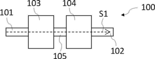
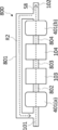
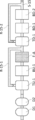
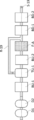
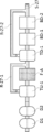
- Drawing 1 is a mimetic diagram showing the filtration device concerning a first embodiment of the present invention.
- the filter device 100 includes a filter 103 as a filter A and a filter 104 (filter BD) different from the filter 103 arranged in series via a pipe 105 between an inflow portion 101 and an outflow portion 102. It is.
- the inflow part 101, the filter 103, the pipe 105, the filter 104, and the outflow part 102 are configured so that the liquid to be purified can be circulated therein, and the flow path S ⁇ b> 1 (liquid to be purified) is connected to the above members. Is formed).
- the inflow part 101 and the outflow part 102 are not particularly limited as long as the liquid to be purified can be introduced into and discharged from the filtration device, but typically, a hollow cylinder having an inlet and an outlet. Shaped pipes (inflow pipe and outflow pipe) and the like. Hereinafter, a mode in which the outflow part and the inflow part are pipes will be described as an example.
- the forms of the inflow part 101, the pipe 105, and the outflow part 102 are not particularly limited, but typically, a hollow cylindrical form formed to allow the liquid to be purified to flow therethrough can be given. Although these material components are not particularly limited, it is preferable that the liquid contact portion (portion where the liquid to be purified may come into contact with when the liquid to be purified is filtered) is formed of a corrosion-resistant material described later. .
- the liquid to be purified introduced from the inflow portion 101 of the filtration device 100 flows through the filtration device 100 along the flow path S1, and is sequentially filtered by the filter 103 (filter A) and the filter 104 (filter BD). And discharged from the outflow portion 102 to the outside of the filtration device 100.
- the form of the liquid to be purified will be described later.
- the filtration device 100 is provided with a pump, a damper, a valve, etc. (not shown) on the flow passage S1 (for example, the inflow portion 101, the pipe 105, and the outflow portion 102) for the purpose of circulating the liquid to be purified. You may have.
- the form of the filter 103 (filter A) and the filter 104 (filter B) is not particularly limited.
- Examples of the form of the filter A and the filter B include a planar shape, a pleated shape, a spiral shape, and a hollow cylindrical shape.
- a core material that is typically formed of a material that allows the liquid to be purified to permeate and / or has a structure that allows the liquid to be purified to permeate, and the core material are wound.
- a cartridge filter having a filter disposed on the core in a rotated form is preferred.
- the core material is not particularly limited, but is preferably formed from a corrosion-resistant material described later.
- the method of arranging the filter is not particularly limited, but typically includes at least one inlet and at least one outlet, and is provided in a housing (not shown) in which at least one flow passage is formed between the inlet and the outlet. It is preferable to arrange
- the flow passage formed in the housing forms a part of the flow passage S1, and the liquid to be purified is filtered by a filter disposed across the flow passage S1 when flowing through the flow passage S1.
- the material of the housing is not particularly limited, and includes any suitable hard impermeable material including any impermeable thermoplastic material that is compatible with the liquid to be purified.
- the housing can be made of a metal such as stainless steel, or a polymer.
- the housing is a polymer such as polyacrylate, polypropylene, polystyrene, or polycarbonate.
- at least a part of the wetted part of the housing preferably 90% of the surface area of the wetted part, more preferably the surface area of the wetted part, in that a more excellent filtration device having the effect of the present invention is obtained.
- 99% is preferably made of a corrosion-resistant material described later.
- the liquid contact part means a part (excluding the filter itself) with which the liquid to be purified may come into contact, and means an inner wall of a unit such as a housing.
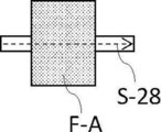
- the filter A has at least one film selected from the group consisting of a first porous film and a second porous film described later.
- the first porous membrane has a porous substrate made of polytetrafluoroethylene (PTFE) and a non-crosslinked coating containing a perfluorosulfonic acid (PFSA) acid polymer formed so as to cover the porous substrate.
- PTFE polytetrafluoroethylene
- PFSA perfluorosulfonic acid
- the porous substrate which the 1st porous film has may have the area
- the porous substrate made of polytetrafluoroethylene is not particularly limited, and those commercially available as PTFE porous substrates can be used as appropriate.
- the method for producing the first porous membrane is not particularly limited, but typically, a polymer dispersion containing a perfluorosulfonic acid (PFSA) polymer is applied to a PTFE porous substrate to form a non-crosslinked coating ( The method of forming the layer) is preferred.
- PFSA perfluorosulfonic acid
- the PFSA polymer dispersion for forming the coating (layer) is not particularly limited, but is available from Solvay Specialty Polymers (Borger, Texas) to AQUIVION® PFSA (eg, Aquivion PFSA D83-24B, Aquivion PFSA -06A, and Aquivion PFSA D79-20BS), which is a short side chain of tetrafluoroethylene and sulfonyl fluoride vinyl ether (SFVE) F 2 C ⁇ CF—O—CF 2 —CF 2 —SO 2 F (SSC) copolymer.
- the ionomer dispersion contains its sulfonic acid form.
- DuPont® Nafion® PFSA polymer dispersion is also preferred as the PFSA polymer dispersion.
- the content of PFSA in the coating solution can be adjusted as appropriate.
- the content is preferably in the range of 0.1 to 3% by mass, more preferably in the range of 0.12 to 2.2% by mass with respect to the total mass of the coating solution.
- the method for forming the coating on the substrate is not particularly limited, and examples thereof include a method of immersing the substrate in the coating solution and a method of spraying the coating solution on the substrate.
- the pore diameter of the first porous membrane is not particularly limited, but is generally preferably 1 to 200 nm and more preferably 10 to 20 nm.
- the pore size is determined by the bubble point of isopropanol (IPA) or HFE-7200 (“Novec 7200”, manufactured by 3M, hydrofluoroether, C 4 F 9 OC 2 H 5 ). Means the pore diameter.
- the thickness of the coating (layer) is not particularly limited, but is generally preferably 5 to 127 ⁇ m, more preferably 13 to 25 ⁇ m.
- the critical wet surface tension (for example, CWST; critical wetting surface tension defined in US Pat. No. 4,925,572) of the first porous membrane (filter A) is not particularly limited.
- CWST can be measured using a set of solutions of constant composition. Each solution has a specific surface tension. The surface tension of the solution ranges from 25 ⁇ 10 ⁇ 5 to 92 ⁇ 10 ⁇ 5 N / cm in small unequal increments.
- the first porous membrane is placed on a white light table, a drop of solution with a constant surface tension is applied to the surface of the membrane, and the droplet is in the first porous The time taken for the light to pass through the membrane and become bright white indicating that light has passed through the membrane is recorded.
- CWST is further known, for example, from US Pat. Nos. 5,152,905, 5,443,743, 5,472,621, and 6,074,869, as known in the art. Can be selected as disclosed in the issue.
- the critical wet surface tension of the first porous membrane is preferably 27 ⁇ 10 ⁇ 5 N / cm or more.
- the inventors have determined that the defect suppression performance of the obtained chemical solution may be affected by the correlation between the physical properties of the liquid to be purified and the critical wet surface tension of the first porous membrane. I caught it.
- the critical wet surface tension of the first porous membrane (filter A) according to the type of the liquid to be purified, a chemical solution having better defect suppression performance can be obtained.
- the critical wet surface tension is 27 ⁇ 10 ⁇ 5 N / cm or more, metal impurities and the like contained in the liquid to be purified can be more efficiently removed, resulting in more excellent defects. A chemical solution having inhibitory performance is obtained.
- the critical wet surface tension is more preferably 30 ⁇ 10 ⁇ 5 N / cm or more, and further preferably 33 ⁇ 10 ⁇ 5 N / cm or more.
- the first porous film has a smaller absolute value of the difference between the critical wet surface tension of the first porous film and the surface tension of the liquid to be purified.
- the surface tension of an organic solvent is generally 15 ⁇ 10 ⁇ 5 to 35 ⁇ 10 ⁇ 5 N / cm so that the surface tension of isopropyl alcohol is 20.8 (25 ° C.) ⁇ 10 ⁇ 5 N / cm.
- the critical wet surface tension of the first porous membrane is generally preferably 40 ⁇ 10 ⁇ 5 N / cm or less.
- the criticality of the first porous membrane is determined.
- a form in which the wet surface tension exceeds 40 ⁇ 10 ⁇ 5 N / cm is also preferable.
- the critical wet surface tension of the first porous membrane can be adjusted by the content of the perfluorosulfonic acid polymer in the non-crosslinked coating containing the perfluorosulfonic acid polymer. Specifically, if the content of the perfluorosulfonic acid polymer in the non-crosslinked coating is increased, a first porous membrane having a higher critical wet surface tension can be easily obtained. If the content is reduced, a first porous membrane having a lower critical wet surface tension can be easily obtained.
- the second porous membrane is a porous membrane containing polytetrafluoroethylene blended with a perfluorosulfonic acid polymer.
- PTFE is not particularly limited, and known PTFE can be used.
- the PFSA blended with PTFE is not particularly limited, but, for example, Solvay Specialty Polymers (Borger, Texas) to Aquivion (registered trademark) PFSA (eg, Aquivion PFSA D83-24B, Aquivion PFSA P83 AFP D79-20BS) which is a short side chain (SSC) copolymer of tetrafluoroethylene and sulfonyl fluoride vinyl ether (SFVE) F 2 C ⁇ CF—O—CF 2 —CF 2 —SO 2 F. Based on.
- the ionomer dispersion contains its sulfonic acid form.
- Another example of a suitable PFSA additive is DuPont® Nafion® PFSA polymer dispersion.
- the content of PFSA is not particularly limited.
- the content of PFSA is typically preferably 1 to 20% by weight, more preferably 1 to 4% by weight, based on the total weight of the blend.
- the method for producing the second porous membrane is not particularly limited, and a known method can be used.
- a lubricant it does not restrict
- PFSA can be sprayed onto the PTFE resin (eg, to improve distribution) prior to physical mixing with the lubricant.
- a required amount of PTFE powder is mixed with a solution of PFSA in an appropriate solvent, for example, an alcohol solvent such as methanol, ethanol, or isopropanol, to obtain a blend.
- an appropriate solvent for example, an alcohol solvent such as methanol, ethanol, or isopropanol
- the blend is then mixed with a odorless mineral spirit, such as a lubricant such as Isopar G, and the resulting paste is subjected to shearing, for example with a twin roller, at least twice, at 2 MPa or more pressure.
- shearing for example with a twin roller, at least twice, at 2 MPa or more pressure.
- each is molded into billets for about 55 seconds.
- the resulting billet is allowed to equilibrate for about 12 hours or longer at room temperature.
- the billet is then extruded into the desired shape.
- extrusion is performed at a die gap size of 26 mm, a maximum pressure, and a constant temperature of 55 ° C. to obtain a tube-shaped PTFE tape.
- the tube-shaped tape is cut open along the central axis and rewound around the pipette to obtain a new billet (uncompressed).
- This new billet is extruded again under the same conditions used in the initial extrusion process.
- This step is added to impart advantageous cross direction mechanical properties to the PTFE tape.
- the calendering is performed at 30 ° C. with a target tape thickness of 200-250 ⁇ m.
- the resulting tape is then dried at 125 ° C. for 1 hour to remove the lubricant from the extruded tape.
- the stretch ratio in the machine direction (MD) and the transverse direction (TD) is 3 at a stretch rate of 300% / second.
- the temperature in the drawing oven is set to 150 ° C.
- the stretched tape is annealed.
- Annealing is performed in an annealing oven, after which the tape is cooled.
- the porosity generated by the stretching is retained during cooling.
- IPA isopropyl alcohol
- the pore diameter of the second porous membrane is not particularly limited, but is preferably 1 to 200 nm, more preferably 10 to 20 nm.
- the thickness of the second porous membrane is not particularly limited, but is generally preferably 5 to 127 ⁇ m, more preferably 0.5 to 1.0 ⁇ m.
- the critical wet surface tension of the second porous membrane (filter A) is preferably 27 ⁇ 10 ⁇ 5 N / cm or more.
- the present inventors have determined that the defect suppression performance of the obtained chemical solution may be influenced by the correlation between the physical properties of the liquid to be purified and the critical wet surface tension of the second porous membrane. It was.
- the critical wet surface tension is 27 ⁇ 10 ⁇ 5 N / cm or more, it is possible to more efficiently remove metal impurities and the like contained in the liquid to be purified, and as a result, a chemical solution having better defect suppression performance. Is obtained.
- the critical wet surface tension is more preferably 30 ⁇ 10 ⁇ 5 N / cm or more, and further preferably 33 ⁇ 10 ⁇ 5 N / cm or more.
- the second porous membrane contains an organic solvent (when it is an “organic solvent-based liquid to be purified” described later) or the like, from the viewpoint of reducing the difference from the surface tension of the liquid to be purified, the second porous membrane
- the critical wet surface tension is preferably 40 ⁇ 10 ⁇ 5 N / cm or less.
- the second porous when the surface tension of the liquid to be purified is larger (for example, when the liquid to be purified contains water or the like, when the liquid to be purified is an “aqueous system liquid to be described later” or the like), the second porous It is also preferred that the critical wet surface tension of the membrane exceeds 40 ⁇ 10 ⁇ 5 N / cm.
- the critical wet surface tension of the second porous membrane can be adjusted by the content of the perfluorosulfonic acid polymer in polytetrafluoroethylene blended with the perfluorosulfonic acid polymer.
- a second porous membrane having a higher critical wetting surface tension can be obtained, and if the content of the perfluorosulfonic acid polymer is decreased, the lower critical wetting is achieved. It is easy to obtain a second porous film having surface tension.
- the filter BD is a filter different from the filter A, and is a filter arranged in series with the filter A on the downstream side of the filter A on the flow path.
- different filters mean that at least one selected from the group consisting of pore diameter, material, and pore structure is different.
- the filter A and the filter BD preferably have different pore diameters, and preferably have different pore diameters and materials, in that a more excellent filtration device having the effect of the present invention can be obtained.
- the different materials typically include forms having different constituent components (material components).
- the pore size of the filter BD is not particularly limited, and a filter having a pore size normally used for filtering the liquid to be purified can be used.
- the pore diameter of the filter is preferably 200 nm or less, more preferably 20 nm or less, still more preferably 10 nm or less, particularly preferably 7 nm or less, and most preferably 5 nm or less.
- limit especially as a lower limit Generally 1 nm or more is preferable from a viewpoint of productivity.
- the filtration device according to the present embodiment has the filter BD on the downstream side of the filter A on the flow path, the fine particles resulting from the filter A can be separated from the liquid to be purified, and more excellent defect suppression. It is easy to obtain chemicals with performance.
- the filtration apparatus of FIG. 1 has one filter BD, as a filtration apparatus which concerns on this embodiment, you may have several filter BD.
- the relationship between the pore diameters of the plurality of filters BD is not particularly limited, but a plurality of pore diameters of the filter BD arranged on the most downstream side on the flow passage are easy in that a chemical solution having better defect suppression performance can be obtained. It is preferable to be the smallest among the filters BD.
- the filter BD arranged on the most downstream side means the filter BD arranged on the most downstream side among all the filters arranged in the flow path.
- the filter BD arranged on the most downstream side contains at least one selected from the group consisting of polyethylene (particularly ultrahigh molecular weight polyethylene; UPE), polytetrafluoroethylene, and nylon as a material component.
- polyethylene particularly ultrahigh molecular weight polyethylene; UPE
- polytetrafluoroethylene particularly ultrahigh molecular weight polyethylene; UPE
- nylon as a material component.
- the filter BD is typically arranged for the purpose of filtering out impurities that may be mixed in the liquid to be purified unintentionally when the product to be purified is filtered by the filter A or the like arranged on the upstream side. Is done.
- the impurities to be removed often differ depending on the material components contained in the filter BD.
- a filter BD containing nylon is presumed that gel-like impurities are easily adsorbed and removed by a hydrophilic layer presumed to be formed on the membrane in the liquid to be purified, and contains ultrahigh molecular weight polyethylene. It is presumed that the filter BD that easily removes particulate impurities due to the sieving effect.
- the filter BD When the liquid to be purified is an organic solvent-based liquid to be purified which will be described later, when the liquid to be purified is passed through a filter BD containing nylon or a filter BD containing ultrahigh molecular weight polyethylene, the filter BD The present inventors have found that unintended impurities may be mixed into the liquid to be purified due to the material. In such a case, if a filter containing polytetrafluoroethylene (preferably made of polytetrafluoroethylene) is arranged as the filter BD arranged on the most downstream side on the flow path, these impurities and the like are also removed. Possible and preferred.
- the pore size of the filter BD is not particularly limited, but is preferably 1 to 20 nm, more preferably 1 to 10 nm, and further preferably 1 to 7 nm.
- the relationship between the hole diameter of the filter A and the hole diameter of the filter BD is not particularly limited, but the hole diameter of the filter BD is preferably smaller than the hole diameter of the filter A.
- the hole diameter of the filter BD is preferably smaller than the hole diameter of the filter A.
- the material of the filter BD is not particularly limited, and may be the same as or different from the filter A. Especially, it is preferable that it differs from the material of the filter A by the point from which the filtration apparatus which has the more excellent effect of this invention is obtained.
- the filter BD includes, as material components, polyamide such as 6-nylon and 6,6-nylon; polyolefin such as polyethylene and polypropylene; polystyrene; polyimide; polyamideimide; poly (meth) acrylate; Polyfluorocarbons such as fluoroalkoxyalkanes, perfluoroethylenepropene copolymers, ethylene-tetrafluoroethylene copolymers, ethylene-chlorotrifluoroethylene copolymers, polychlorotrifluoroethylene, polyvinylidene fluoride, and polyvinyl fluoride; polyvinyl alcohol; polyester Cellulose; preferably containing cellulose acetate and the like.
- polyamide such as 6-nylon and 6,6-nylon
- polyolefin such as polyethylene and polypropylene
- polystyrene polyimide
- polyamideimide poly (meth) acrylate
- Polyfluorocarbons such as fluoroalkoxyalkan
- nylon especially 6,6-nylon is preferred
- polyolefin especially polyethylene is preferred
- polyfluorocarbon in particular, polytetrafluoroethylene (PTFE) and perfluoroalkoxyalkane (PFA) are preferred.
- PTFE polytetrafluoroethylene
- PFA perfluoroalkoxyalkane
- the filter may be surface-treated.
- the surface treatment method is not particularly limited, and a known method can be used. Examples of the surface treatment method include chemical modification treatment, plasma treatment, hydrophobic treatment, coating, gas treatment, and sintering.
- Plasma treatment is preferable because the surface of the filter is hydrophilized.
- the water contact angle on the surface of the filter medium hydrophilized by plasma treatment is not particularly limited, but the static contact angle at 25 ° C. measured with a contact angle meter is preferably 60 ° or less, more preferably 50 ° or less. 30 ° or less is more preferable.
- the filter is preferably a filter in which the above-mentioned materials are used as base materials and ion exchange groups are introduced into the base materials.
- a filter including a layer containing a substrate having an ion exchange group on the surface of the substrate is preferable.
- the surface-modified base material is not particularly limited, and those in which an ion exchange group is introduced into the polymer are preferable in terms of easier production.
- the ion exchange group examples include a sulfonate group, a carboxy group, and a phosphate group as a cation exchange group, and a quaternary ammonium group as an anion exchange group.
- the method for introducing the ion exchange group into the polymer is not particularly limited, but a method of reacting a compound having an ion exchange group and a polymerizable group with the polymer and typically grafting is exemplified.
- the method for introducing the ion exchange group is not particularly limited, but the resin fibers are irradiated with ionizing radiation ( ⁇ ray, ⁇ ray, ⁇ ray, X ray, electron beam, etc.) and an active moiety ( Radical).
- ionizing radiation ⁇ ray, ⁇ ray, ⁇ ray, ⁇ ray, X ray, electron beam, etc.
- Radical an active moiety
- the resin having the produced polymer as a side chain is contact-reacted with a compound having an anion exchange group or a cation exchange group, whereby an ion exchange group is introduced into the graft-polymerized side chain polymer to obtain a final product. It is done.
- the filter may have a configuration in which a woven fabric or a non-woven fabric in which an ion exchange group is formed by a radiation graft polymerization method and a conventional glass wool, woven fabric, or a non-woven fabric filter material.
- the filter BD is at least one selected from the group consisting of polyolefin, polyamide, polyfluorocarbon, polystyrene, polysulfone, and polyethersulfone, in that a filtration device having a better effect of the present invention can be obtained. It is preferable that the filter BD is made of at least one material component selected from the group consisting of polyolefin, polyamide, polyfluorocarbon, polystyrene, polysulfone, and polyethersulfone.
- the polyolefin include polyethylene and polypropylene. Among them, ultrahigh molecular weight polyethylene is preferable.
- the polyamide include 6-nylon and 6,6-nylon.
- Polyfluorocarbons include polytetrafluoroethylene (PTFE), perfluoroalkoxyalkanes, perfluoroethylene propene copolymers, ethylene-tetrafluoroethylene copolymers, ethylene-chlorotrifluoroethylene copolymers, polychlorotrifluoroethylene, polyvinylidene fluoride, and And polyvinyl fluoride, and the like.
- PTFE polytetrafluoroethylene
- perfluoroalkoxyalkanes perfluoroethylene propene copolymers
- ethylene-tetrafluoroethylene copolymers ethylene-chlorotrifluoroethylene copolymers
- polychlorotrifluoroethylene polyvinylidene fluoride
- polyvinyl fluoride and the like.
- PTFE is preferable.
- the pore structure of the filter BD is not particularly limited, and may be appropriately selected according to the component of the liquid to be purified.
- the pore structure of the filter BD means a pore size distribution, a positional distribution of pores in the filter, a shape of the pores, and the like. It can be controlled.
- a porous film can be obtained by forming a powder of resin or the like by sintering, and a fiber film can be obtained by forming by a method such as electrospinning, electroblowing, or meltblowing. These have different pore structures.
- Porous membrane is a membrane that retains components in the liquid to be purified, such as gels, particles, colloids, cells, and polyoligomers, but components that are substantially smaller than the pores pass through the pores. Means. The retention of the components in the liquid to be purified by the porous membrane may depend on operating conditions such as surface speed, use of surfactant, pH, and combinations thereof, and the pore size of the porous membrane, It may depend on the structure and the size of the particles to be removed and the structure (such as hard particles or gel).
- UPE (ultra high molecular weight polyethylene) filters are typically sieving membranes.
- sieving membrane is meant a membrane that captures particles primarily through a sieving retention mechanism, or a membrane that is optimized to capture particles via a sieving retention mechanism.
- Typical examples of sieve membranes include, but are not limited to, polytetrafluoroethylene (PTFE) membranes and UPE membranes.
- PTFE polytetrafluoroethylene
- the “sieving holding mechanism” refers to holding the result due to the removal target particle being larger than the pore diameter of the porous membrane.
- Sieve retention can be improved by forming a filter cake (aggregation of particles to be removed on the surface of the membrane). The filter cake effectively functions as a secondary filter.
- the pore structure of the porous membrane is not particularly limited, but examples of the pore shape include a lace shape, a string shape, and a node shape. It is done.
- the distribution of the pore size in the porous membrane and the distribution of the positions in the membrane are not particularly limited. The size distribution may be smaller and the distribution position in the film may be symmetric. Further, the size distribution may be larger, and the distribution position in the film may be asymmetric (the above film is also referred to as “asymmetric porous film”). In an asymmetric porous membrane, the pore size varies in the membrane and typically the pore size increases from one surface of the membrane to the other surface of the membrane.
- the surface on the side having many pores with a large pore diameter is referred to as “open side”, and the surface on the side having many pores with a small pore diameter is also referred to as “tight side”.
- examples of the asymmetric porous membrane include those having the smallest pore size at a certain position within the thickness of the membrane (this is also referred to as “hourglass shape”).
- the primary side is a larger-sized hole, in other words, if the primary side is the open side, a prefiltration effect can be produced.
- the porous membrane may include a thermoplastic polymer such as PESU (polyethersulfone), PFA (perfluoroalkoxyalkane, copolymer of tetrafluoroethylene and perfluoroalkoxyalkane), polyamide, and polyolefin.
- PESU polyethersulfone
- PFA perfluoroalkoxyalkane, copolymer of tetrafluoroethylene and perfluoroalkoxyalkane
- polyamide polyolefin
- polytetrafluoroethylene may be included.
- a porous membrane contains ultra high molecular weight polyethylene as a material component.
- Ultra high molecular weight polyethylene means a thermoplastic polyethylene having an extremely long chain, and preferably has a molecular weight of 1 million or more, typically 2 to 6 million.
- non-sieving membranes include, but are not limited to, nylon membranes such as nylon-6 membrane and nylon-6,6 membrane.
- the “non-sieving” retention mechanism refers to retention caused by a pressure drop of the filter or a mechanism such as obstruction, diffusion and adsorption that is not related to the pore size.
- Non-sieving retention includes retention mechanisms such as obstruction, diffusion and adsorption that remove particles to be removed from the liquid to be purified regardless of the pressure drop of the filter or the pore size of the filter.
- Adsorption of particles on the filter surface can be mediated, for example, by intermolecular van der Waals forces and electrostatic forces.
- a disturbing effect occurs when particles moving through a non-sieving membrane layer having a serpentine path cannot be redirected fast enough to not contact the non-sieving membrane.
- Particle transport by diffusion arises primarily from the random or Brownian motion of small particles that create a certain probability that the particles will collide with the filter media. If there is no repulsive force between the particles and the filter, the non-sieving retention mechanism can be active.
- the material of the fiber membrane is not particularly limited as long as it is a polymer capable of forming a fiber membrane.
- the polymer include polyamide.
- the polyamide include nylon 6 and nylon 6,6.
- the polymer that forms the fiber membrane may be poly (ether sulfone).
- the surface energy of the fiber membrane is preferably higher than the polymer that is the material of the porous membrane on the secondary side. Examples of such a combination include a case where the material of the fiber membrane is nylon and the porous membrane is polyethylene (UPE).
- the method for producing the fiber membrane is not particularly limited, and a known method can be used.
- Examples of the method for producing a fiber membrane include electrospinning, electroblowing, and meltblowing.
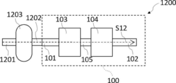
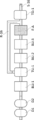
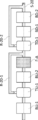
- FIG. 2 is a schematic diagram showing a filtration device according to the second embodiment of the present invention.
- the filtration device 200 is a filtration device in which a filter 103 that is a filter A and a filter 201 (filter BU) that is different from the filter 103 are arranged in series via a pipe 202 between an inflow portion 101 and an outflow portion 102. .
- the inflow part 101, the filter 201, the pipe 202, the filter 103, and the outflow part 102 are configured so that the liquid to be purified can be circulated therein, and the above-described members are connected to each other to connect the flow path S ⁇ b> 2 (liquid to be purified). Is formed).
- each filter and piping is the same as that of the filtration device according to the first embodiment already described, and the following description is limited to only the parts different from the first embodiment. Do. Therefore, the matter which is not demonstrated below is the same as that of the filtration apparatus which concerns on 1st embodiment.
- the filter BU is a filter different from the filter A, and is a filter arranged in series with the filter A on the upstream side of the filter A on the flow path. On the flow passage, the inflow portion is on the upstream side, and the outflow portion is on the downstream side.
- the filter A and the filter BU are preferably different from each other in terms of obtaining a more excellent filtration device having the effect of the present invention, and the pore diameter and the material are preferably different from each other.
- the pore size of the filter BU is not particularly limited, and a filter having a pore size normally used for filtering the liquid to be purified can be used.
- the pore diameter of the filter is preferably 1 nm or more, more preferably 3 nm or more, and still more preferably 10 nm or more.
- limit especially as an upper limit 1.0 micrometer or less is preferable, other than the form used as the filter C mentioned later, less than 200 nm is more preferable, less than 100 nm is still more preferable, and 50 nm or less is especially preferable.
- the hole diameter of at least 1 filter BU is in the said range, and the hole diameter of filter BU arrange
- the filter A when a filtration device in which a filter BU having a hole diameter of 20 nm or more is arranged on the upstream side of the filter A on the flow path S2, the filter A is less likely to be clogged. It has been found that the lifetime of A can be further extended. As a result, it is possible to obtain a filtration device that can stably provide a chemical having superior defect suppression performance.
- the relationship between the hole diameter of the filter A and the hole diameter of the filter BU is not particularly limited, but the hole diameter of the filter BU is preferably larger than the hole diameter of the filter A.
- the filtration device according to the present embodiment may have a plurality of filters BU.
- the relationship between the pore sizes of the plurality of filters BU is not particularly limited.
- the pore size of the filter BU arranged on the most upstream side in the flow passage is the maximum in that a chemical solution having better defect suppression performance is easily obtained. It is preferable to become. By doing in this way, the lifetime of the filter (including the filter A) disposed downstream of the most upstream filter BU can be extended, and as a result, a chemical solution having better defect suppression performance can be stabilized. Filtration device that can be provided.
- the resin having an ion exchange group is not particularly limited, and a filter containing a material component capable of removing ions (for example, metal ions) by the non-sieving effect described in the first embodiment can be used.
- a filter containing a material component capable of removing ions (for example, metal ions) by the non-sieving effect described in the first embodiment can be used.
- an anion exchange group is preferable as the ion exchange group, and examples of the anion exchange group include a quaternary ammonium group.
- filter BU contains resin which has an anion exchange group as a material component, the chemical
- a material component of the filter BU a material in which an anion exchange group is introduced into a base material such as polyfluorocarbon and polyolefin is more preferable.
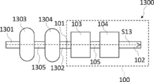
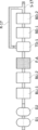
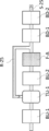
- Drawing 3 is a mimetic diagram of a filtration device showing a modification of a filtration device concerning a second embodiment of the present invention.
- the filtration device 300 includes a filter 103 that is a filter A, a filter 201 that is a filter BU, and a filter 104 that is a filter BD between the inflow portion 101 and the outflow portion 102.
- the filter 201 and the filter 103 And a filter 104 in which the filter 104 is arranged in series via a pipe 301 and a pipe 302.
- each filter and piping is the same as the filtration apparatus according to the first embodiment already described, and the following description is limited to only the parts different from the first embodiment. Do. Therefore, the matter which is not demonstrated below is the same as that of the filtration apparatus which concerns on 1st embodiment.
- the inflow portion 101, the filter 201, the pipe 301, the filter 103, the pipe 302, and the filter 104 are configured so that the liquid to be purified can be circulated therein, and the above-described members are connected to the flow path S3 (liquid to be purified). Is formed).
- the configuration of the piping and each filter is as described above. Since the filter 300 has the filter BU on the upstream side of the filter A on the flow path, the filter A has a longer life, and has the filter BD on the downstream side of the filter A on the flow path. Fine particles mixed in the purified liquid can be efficiently removed, and as a result, a chemical liquid having further excellent defect suppressing performance can be easily obtained.
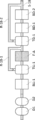
- FIG. 4 is a schematic view showing a filtration device according to the third embodiment of the present invention.
- the filtration device 400 further includes a tank 401 disposed in series with the filter A between the inflow portion 101 and the outflow portion 102 and upstream of the filter 103 (filter A) on the flow path S4. It is.
- the tank 401, the filter 103 (filter A), and the filter 104 (filter BD) are arranged in series via the pipe 402 and the pipe 105.
- the tank 401 constitutes the flow path S4 together with the above-described filter, piping, and the like.
- each filter and piping is the same as that of the filtration device according to the first embodiment already described, and the following description is limited to only the parts different from the first embodiment. Do. Therefore, the matter which is not demonstrated below is the same as that of the filtration apparatus which concerns on 1st embodiment.
- the filtration apparatus Since the filtration apparatus according to the present embodiment has a tank on the upstream side of the filter 103, the liquid to be purified to be circulated through the filter 103 can be retained and homogenized, resulting in more excellent defects. A chemical solution having inhibitory performance is obtained.
- the liquid to be purified is returned to the flow path S4 from the downstream of the filter 103 (filter A) to the upstream of the filter 103 to the flow path S4.
- a tank 401 can be used to receive the liquid to be purified. In this way, since the returned liquid to be purified is retained and homogenized, it can be passed through the filter 103 again, so that a chemical solution having further superior defect suppression performance can be obtained.
- the material of the tank 401 is not particularly limited, but the same material as the housing material described above can be used, and at least a part of the wetted part (preferably 90% or more of the surface area of the wetted part, more preferably 99% or more) is preferably made of a corrosion-resistant material described later.
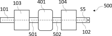
- FIG. 5 is a schematic diagram showing a modification of the filtration device according to the third embodiment of the present invention.
- the filtration device 500 further includes a tank 401 arranged in series with the filter A between the inflow portion 101 and the outflow portion 102 and on the downstream side of the filter 103 (filter A) on the flow path S5. It is.
- the filter 103 (filter A), the tank 401, and the filter 104 (filter BD) are arranged in series via a pipe 501 and a pipe 502.
- the tank 401 constitutes the flow path S5 together with the above-described filter, piping, and the like.
- each filter and piping is the same as that of the filtration device according to the first embodiment already described, and the following description is limited to only parts different from the first embodiment. Do. Therefore, the matter which is not demonstrated below is the same as that of the filtration apparatus which concerns on 1st embodiment.
- the filtration device Since the filtration device according to this embodiment has a tank on the downstream side of the filter A, the liquid to be purified filtered by the filter A can be retained.
- the liquid to be purified when the liquid to be purified is returned from the downstream side of the filter 103 (filter A) to the flow path S4 to the upstream side of the filter 103 with respect to the flow path S4, the return is returned.
- a tank 401 can be used to retain the liquid to be purified. In this way, since the liquid to be purified to be returned is retained and homogenized, it can be passed through the filter 103 again, so that a chemical solution having further superior defect suppression performance can be obtained.
- the tank 401 is disposed on the upstream side of the filter 104 (filter BD) on the flow passage S5.
- the flow passage S5 is used. It may be arranged on the downstream side of the filter 104 above.
- the tank 401 can be used to retain the liquid to be returned that is to be returned during circulation filtration.
- it can be the base point of the circulation filtration.
- the filter on the upstream side of the tank 401 filter 103 in the filtration device 500
- the filter on the downstream side of the tank 401 filtration
- the filter 1014 is often the object of circulation filtration as a reference filter.
- the base point of the circulation filtration includes both the case where the tank constitutes a return flow passage and the case where the downstream pipe of the tank constitutes a return flow passage.
- the tank 401 is disposed on the upstream side of the filter 104 (filter BD).
- the upstream side or the downstream side of the tank 401 in the flow path S5 can be the target of the circulation filtration.
- the upstream side of the tank 401 is the target of circulation filtration, the intention is that the liquid to be purified that has been sufficiently filtered by the filter A is finally passed through the filter A.
- the flow that removes fine particles mixed in the liquid to be purified without using the filter 104 can be adopted. As a result, the life of the filter BD becomes longer, and a chemical solution having excellent defect suppression performance can be manufactured more stably over a long period of time. is there.
- the filter BU and the filter A are arranged in series in this order (for example, the second embodiment), and the filter BU, the filter A, and the filter BD are in series in this order.
- a tank 401 may be further provided on the upstream side of the filter A.
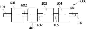
- FIG. 6 is a schematic view showing a filtration device according to the fourth embodiment of the present invention.
- a filter 601 which is a filter C
- a tank 401
- a filter 103 which is a filter A
- a filter 104 which is a filter BD
- the inflow part 101, the filter 601, the pipe 602, the tank 401, the pipe 402, the filter 103, the pipe 105, the filter 104, and the outflow part 102 form the flow path S6.
- each filter and piping is the same as that of the filtration device according to the first embodiment already described, and the following description is limited to only parts different from the first embodiment. Do. Therefore, the matter which is not demonstrated below is the same as that of the filtration apparatus which concerns on 1st embodiment.
- the filter 601 (filter C) is a filter having a pore diameter of 10 nm or more disposed on the upstream side of the tank 401 in the flow path S6.
- a filter having a predetermined hole diameter is disposed upstream of the tank 401 in the flow passage S6, so that impurities contained in the liquid to be purified that flows in from the inflow portion 101 are preliminarily removed. Since it can be removed using the filter 601, the amount of impurities mixed in the flow path after the pipe 602 can be further reduced. For this reason, the lifetime of the filter A and the filter BD (and the filter BU if the filter BU is disposed) in the subsequent stage can be further extended. As a result, according to the filtration device, it is possible to stably produce a chemical solution having better defect suppression performance.
- the form of the filter C is not particularly limited, and may be the same filter as the filter A already described, or may be a different filter (filter B). Especially, it is preferable that it is a filter (filter B) different from the filter A at the point which can obtain the chemical
- the pore diameter is not particularly limited, and is preferably 10 nm or more, more preferably 20 nm or more, still more preferably more than 50 nm, and particularly preferably 100 nm or more.
- the filter A and the filter BD are arranged in series in this order on the flow path (for example, the second embodiment), and the filter BU, the filter A, and
- a tank is further provided on the downstream side of the filter A, and a filter C is provided on the upstream side of the tank. Good.
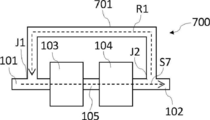
- FIG. 7 is a schematic view of a filtration device according to the fifth embodiment of the present invention.
- the filtration device 700 includes an inflow portion 101, an outflow portion 102, a filter 103 that is a filter A, and a filter 104 that is a filter BD.
- the filter 103 and the filter 104 are connected to the inflow portion 101 and the outflow portion 102.
- the inflow portion 101, the filter 103, the pipe 105, the filter 104, and the outflow portion 102 form a flow passage S7.
- each filter and piping is the same as the filtration apparatus according to the first embodiment already described, and the following description is limited to only parts different from the first embodiment. Do. Therefore, the matter which is not demonstrated below is the same as that of the filtration apparatus which concerns on 1st embodiment.
- the filtration device 700 can return the liquid to be purified from the downstream side of the filter 104 (reference filter) in the flow path S7 to the upstream side of the filter 103 (and upstream of the reference filter) in the flow path S7.
- a path R1 is formed.
- the filtration device 700 has a return pipe 701, and the return flow passage R ⁇ b> 1 is formed by the pipe 701.
- One end of the pipe 701 is connected to the flow path S7 on the downstream side of the filter 104 (and the filter 103), and the other end is connected to the flow path S7 on the upstream side of the filter 103.
- a pump, a damper, a valve, and the like may be disposed on the return flow passage R1.
- the liquid to be purified that circulates in the return flow passage R1 and is returned to the upstream side (in the flow passage S7) of the filter 103 is filtered by the filter 103 and the filter 104 in the process of flowing through the flow passage S7 again.
- This is called circulation filtration, and the filtration device 700 can carry out circulation filtration, and as a result, a chemical solution having better defect suppression performance can be easily obtained.
- the liquid to be purified can be returned from the downstream side of the filter 104 (filter BD, reference filter) to the upstream side of filter A (and the filter BD; upstream side of the reference filter) on the flow path S7.
- the piping 701 is disposed, the filtration apparatus according to the present embodiment can return the liquid to be purified from the downstream side of the filter A to the upstream side of the filter A using the filter A as a reference filter on the flow path. It may be configured.
- the return flow passage may be formed by a pipe connecting the pipe 105 and the inflow portion 101.
- the filter A is used as a reference filter, from the downstream side of the reference filter to the upstream side of the filter BU (and the upstream side of the reference filter).
- a return flow path that can return the liquid to be purified may be formed.
- the return flow passage R1 is formed only from the pipe, but it may be formed from one or more tanks and pipes already described.
- FIG. 8 is a schematic diagram illustrating a modification of the filtration device according to the fifth embodiment of the present invention.
- the filtration device 800 includes an inflow portion 101, tanks 401 (a) and 401 (b), an outflow portion 102, a filter 103 that is a filter A, and a filter 104 that is a filter BD.
- the tank 401 (a), The filter 103, the filter 104, and 401 (b) are arranged in series between the inflow portion 101 and the outflow portion 102, and the inflow portion 101, the tank 401 (a), the pipe 802, the filter 103, and the pipe 803.
- the filter 104, the pipe 804, the tank 401 (b), and the outflow portion 102 form a flow passage S8.
- each filter and piping is the same as that of the filtration device according to the first embodiment already described, and the following description is limited to only the parts different from the first embodiment. Do. Therefore, the matter which is not demonstrated below is the same as that of the filtration apparatus which concerns on 1st embodiment.
- the filtration device 800 is upstream of the tank 401 (a) disposed on the upstream side of the filter 103 on the flow path S8 from the downstream side of the tank 401 (b) disposed on the downstream side of the filter 104 on the flow path S8.
- a return flow passage R2 capable of returning the liquid to be purified to the side is formed.
- One end of the pipe 801 is connected to the flow path S8 on the downstream side of the tank 401 (b), and the other end is connected to the flow path S8 on the upstream side of the tank 401 (a).
- a pump, a damper, a valve, and the like may be disposed in the return flow passage R2.
- the base point of the return flow passage R2 is disposed on the downstream side of the tank 401 (b) on the flow passage, and the end point is disposed on the upstream side of the tank 401 (a) on the flow passage.
- the liquid to be purified can be returned after being retained during circulation filtration, and can be recirculated after being retained, resulting in a chemical solution having better defect suppression performance. It is done.
- the form which tank 401 (b) and the piping 801 connect directly may be sufficient, and the form which the tank 401 (a) and the piping 801 connect directly may be sufficient. It may be a form provided with both.
- FIG. 9 is a schematic view of a filtration device according to the fifth embodiment of the present invention.
- the filtration device 900 includes an inflow portion 101, an outflow portion 102, a filter 103 that is a filter A, and a filter 104 that is a filter BD.
- the filter 103 and the filter 104 are connected to the inflow portion 101 and the outflow portion 102.
- a flow passage S9 from the inflow portion 101 to the outflow portion 102 is formed.
- the inflow portion 101, the filter 103, the pipe 105, the filter 104, and the outflow portion 102 form a flow passage S9.
- the filtration device 900 is formed with a return flow path R3 that can return the liquid to be purified from the downstream side of the filter 104 on the flow path S9 to the downstream side of the filter 103 and the upstream side of the filter 104 on the flow path S9.
- the filtration device 900 has a return pipe 901, and a return flow passage R ⁇ b> 3 is formed by the pipe 901.
- One end of the pipe 901 is connected to the flow path S9 on the downstream side of the filter 104, and the other end is connected to the flow path S9 on the upstream side of the filter 104 and the downstream side of the filter 103.
- a pump, a damper, a valve, and the like may be disposed on the return flow passage R3.
- the liquid to be purified that circulates in the return flow path R2 and is returned to the downstream side of the filter 103 and upstream of the filter 104 is filtered by the filter 104 in the process of flowing again through the flow path S9.
- the filtration device 900 can perform circulation filtration, and as a result, a chemical solution having better defect suppression performance can be easily obtained.
- the liquid to be purified is returned from the downstream side of the filter 104 (filter BD) on the flow path S9 to the downstream side of the filter A on the flow path S9 and to the upstream side of the filter BD.
- the pipe 901 is arranged so as to be able to be used, as a filtration device according to the present embodiment, the liquid to be purified is located on the flow path from the downstream side of the filter B to the downstream side of the filter A and upstream of the filter B. As long as it can be returned.
- FIG. 10 is a schematic diagram illustrating a modification of the filtration device according to the present embodiment.
- the filtration apparatus 1000 includes an inflow portion 101, an outflow portion 102, a filter 103 that is a filter A, a filter 104-1 (reference filter) that is a filter BD, and a filter 104-2.
- the filtering device 104-1 and the filter 104-2 are arranged in series between the inflow portion 101 and the outflow portion 102, and have a flow passage S10 extending from the inflow portion 101 to the outflow portion 102.
- the inflow part 101, the filter 103, the pipe 105, the filter 104-1, the pipe 1001, the filter 104-2, and the outflow part 102 form a flow path S10.
- each filter and piping is the same as that of the filtration device according to the first embodiment already described, and the following description is limited to only parts different from the first embodiment. Do. Therefore, the matter which is not demonstrated below is the same as that of the filtration apparatus which concerns on 1st embodiment.
- the filtering device 1000 is located on the flow path S10 from the downstream side of the filter 104-1 (reference filter) to the downstream side of the filter 103 and the upstream side of the filter 104-1 (reference filter) with respect to the flow path S10.
- a return flow passage R4 capable of returning the liquid to be purified is formed.
- the filtration device 1000 has a return pipe 1002, and a return flow passage R ⁇ b> 4 is formed by the pipe 1002.
- One end of the pipe 1002 is connected to the flow path S10 on the downstream side of the filter 103 and upstream of the filter 104-1, and the other end is connected to the flow path S10 on the downstream side of the filter 104-1 and upstream of the filter 104-2.
- a pump, a damper, a valve, and the like may be disposed in the return flow passage R4.
- the liquid to be purified returned to the upstream side of the filter 104-1 on the downstream side of the filter 103 on the flow path S10 by the return flow path R4 is again filtered by the filter 104-1 in the process of flowing through the flow path S10. Filtered.
- circulation filtration can be performed, and as a result, a chemical solution having better defect suppression performance can be easily obtained.
- the flow path R4 is formed, the filtration device according to the present embodiment is not limited to the above, and the liquid to be purified can be returned from the downstream side of the filter 104-2 to the upstream side of the filter 104-2.
- a return flow passage capable of returning the liquid to be purified from the downstream side of the filter 104-2 in which the return flow passage is formed to the downstream side of the filter A and the upstream side of the filter 104-1 is formed.
- a filtration device in which a return flow passage capable of returning from the downstream side of the filter 104-1 or the filter 104-2 to the upstream side of the filter 103 is formed.
- the method for producing a chemical solution according to the embodiment of the present invention is a method for producing a chemical solution by purifying the liquid to be purified to obtain the chemical solution, and the chemical solution is filtered by filtering the liquid to be purified using the filtration device described above. Having a filtration step to obtain.
- [Purified liquid] Although it does not restrict
- the solvent include an organic solvent and water, and it is preferable to contain an organic solvent.
- the water content exceeds 50% by mass with respect to the total mass of the solvent contained in the liquid to be purified.
- Organic solvent-based liquid to be purified contains a solvent, and the content of the organic solvent is 50% by mass or more based on the total mass of the solvent contained in the liquid to be purified.
- the liquid to be purified contains an organic solvent.
- the content of the organic solvent in the liquid to be purified is not particularly limited, but generally 99.0% by mass or more is preferable with respect to the total mass of the liquid to be purified. Although it does not restrict
- An organic solvent may be used individually by 1 type, or may use 2 or more types together. When two or more organic solvents are used in combination, the total content is preferably within the above range.
- the organic solvent intends the liquid organic compound contained with content exceeding 10,000 mass ppm per component with respect to the total mass of the said to-be-purified liquid. That is, in this specification, the liquid organic compound contained exceeding 10,000 mass ppm with respect to the total mass of the liquid to be purified corresponds to the organic solvent.
- the liquid state means a liquid at 25 ° C. and atmospheric pressure.
- the type of the organic solvent is not particularly limited, and a known organic solvent can be used.
- the organic solvent include alkylene glycol monoalkyl ether carboxylate, alkylene glycol monoalkyl ether, alkyl lactate ester, alkyl alkoxypropionate, cyclic lactone (preferably having 4 to 10 carbon atoms), and monoketone which may have a ring. Examples thereof include compounds (preferably having 4 to 10 carbon atoms), alkylene carbonate, alkyl alkoxyacetate, and alkyl pyruvate.
- the organic solvent for example, those described in JP-A-2016-57614, JP-A-2014-219664, JP-A-2016-138219, and JP-A-2015-135379 may be used. Good.
- organic solvents examples include propylene glycol monomethyl ether (PGMM), propylene glycol monoethyl ether (PGME), propylene glycol monopropyl ether (PGMP), propylene glycol monomethyl ether acetate (PGMEA), ethyl lactate (EL), methyl methoxypropionate (MPM), cyclopentanone (CyPn), cyclohexanone (CyHe), ⁇ -butyrolactone ( ⁇ BL), diisoamyl ether (DIAE), butyl acetate (nBA), isoamyl acetate (iAA), isopropanol (IPA), 4-methyl -2-pentanol (MIBC), dimethyl sulfoxide (DMSO), n-methyl-2-pyrrolidone (NMP), diethylene glycol (DEG), ethylene glycol (E G), dipropylene glycol (DPG), propylene glycol (PG), ethylene carbonate (EC), propylene carbonate (
- the kind and content of the organic solvent in the liquid to be purified can be measured using a gas chromatograph mass spectrometer.
- the liquid to be purified may contain components other than those described above.
- examples of other components include inorganic substances (metal ions, metal particles, metal oxide particles, and the like), resins, organic substances other than resins, and water.
- the liquid to be purified may contain an inorganic substance. It does not restrict
- the metal-containing particles only need to contain metal atoms, and the form is not particularly limited.
- a single metal atom, a compound containing a metal atom (hereinafter also referred to as “metal compound”), a complex thereof, and the like can be given.
- the metal-containing particles may contain a plurality of metal atoms.
- the composite is not particularly limited, but a so-called core-shell type particle having a single metal atom and a metal compound covering at least a part of the single metal atom, a solid solution containing a metal atom and another atom Particles, eutectic particles containing metal atoms and other atoms, aggregate particles of simple metal atoms and metal compounds, aggregate particles of different types of metal compounds, and continuous from the particle surface toward the center or Examples thereof include a metal compound whose composition changes intermittently.
- the atom other than the metal atom contained in the metal compound is not particularly limited, and examples thereof include a carbon atom, an oxygen atom, a nitrogen atom, a hydrogen atom, a sulfur atom, and a phosphorus atom.
- the metal-containing particles may contain the above metal atoms alone or in combination of two or more.
- the inorganic substance may be added to the liquid to be purified, or may be unintentionally mixed with the liquid to be purified in the manufacturing process.
- medical solution for example, when an inorganic substance is contained in the raw material (for example, organic solvent) used for manufacture of a chemical
- the liquid to be purified may contain a resin.
- the chemical solution may further contain a resin.
- a resin P having a group that decomposes by the action of an acid to generate a polar group is more preferable.
- the resin is more preferably a resin having a repeating unit represented by the formula (AI) described later, which is a resin whose solubility in a developer containing an organic solvent as a main component is reduced by the action of an acid.
- the resin having a repeating unit represented by the formula (AI) described later has a group (hereinafter also referred to as “acid-decomposable group”) that decomposes by the action of an acid to generate an alkali-soluble group.
- Examples of polar groups include alkali-soluble groups.
- Examples of the alkali-soluble group include a carboxy group, a fluorinated alcohol group (preferably a hexafluoroisopropanol group), a phenolic hydroxyl group, and a sulfo group.
- the polar group is protected by a group capable of leaving by an acid (acid leaving group).
- the acid leaving group include -C (R 36 ) (R 37 ) (R 38 ), -C (R 36 ) (R 37 ) (OR 39 ), and -C (R 01 ) (R 02 ) (OR 39 ) and the like.
- R 36 to R 39 each independently represents an alkyl group, a cycloalkyl group, an aryl group, an aralkyl group or an alkenyl group.
- R 36 and R 37 may be bonded to each other to form a ring.
- R 01 and R 02 each independently represents a hydrogen atom, an alkyl group, a cycloalkyl group, an aryl group, an aralkyl group or an alkenyl group.
- the resin P preferably contains a repeating unit represented by the formula (AI).
- Xa 1 represents a hydrogen atom or an alkyl group which may have a substituent.
- T represents a single bond or a divalent linking group.
- Ra 1 to Ra 3 each independently represents an alkyl group (linear or branched) or a cycloalkyl group (monocyclic or polycyclic). Two of Ra 1 to Ra 3 may combine to form a cycloalkyl group (monocyclic or polycyclic).
- Examples of the alkyl group that may have a substituent represented by Xa 1 include a methyl group and a group represented by —CH 2 —R 11 .
- R 11 represents a halogen atom (fluorine atom or the like), a hydroxyl group, or a monovalent organic group.
- Xa 1 is preferably a hydrogen atom, a methyl group, a trifluoromethyl group or a hydroxymethyl group.
- Examples of the divalent linking group for T include an alkylene group, —COO—Rt— group, —O—Rt— group, and the like.
- Rt represents an alkylene group or a cycloalkylene group.
- T is preferably a single bond or a —COO—Rt— group.
- Rt is preferably an alkylene group having 1 to 5 carbon atoms, more preferably a —CH 2 — group, a — (CH 2 ) 2 — group, or a — (CH 2 ) 3 — group.
- the alkyl group for Ra 1 to Ra 3 is preferably an alkyl group having 1 to 4 carbon atoms.
- Examples of the cycloalkyl group represented by Ra 1 to Ra 3 include a monocyclic cycloalkyl group such as a cyclopentyl group or a cyclohexyl group, or a multicyclic group such as a norbornyl group, a tetracyclodecanyl group, a tetracyclododecanyl group, or an adamantyl group.
- a cyclic cycloalkyl group is preferred.
- the cycloalkyl group formed by combining two of Ra 1 to Ra 3 includes a monocyclic cycloalkyl group such as a cyclopentyl group or a cyclohexyl group, or a norbornyl group, a tetracyclodecanyl group, or a tetracyclododecanyl group. Or a polycyclic cycloalkyl group such as an adamantyl group is preferred. A monocyclic cycloalkyl group having 5 to 6 carbon atoms is more preferable.
- the cycloalkyl group formed by combining two of Ra 1 to Ra 3 is, for example, a group in which one of the methylene groups constituting the ring has a hetero atom such as an oxygen atom or a hetero atom such as a carbonyl group. It may be replaced.
- the repeating unit represented by the formula (AI) preferably has, for example, an embodiment in which Ra 1 is a methyl group or an ethyl group, and Ra 2 and Ra 3 are bonded to form the above-described cycloalkyl group.
- Each of the above groups may have a substituent.
- substituents include an alkyl group (1 to 4 carbon atoms), a halogen atom, a hydroxyl group, an alkoxy group (1 to 4 carbon atoms), a carboxy group, And alkoxycarbonyl groups (having 2 to 6 carbon atoms) and the like, and those having 8 or less carbon atoms are preferred.
- the content of the repeating unit represented by the formula (AI) is preferably from 20 to 90 mol%, more preferably from 25 to 85 mol%, further preferably from 30 to 80 mol%, based on all repeating units in the resin P. preferable.
- the resin P preferably contains a repeating unit Q having a lactone structure.
- the repeating unit Q having a lactone structure preferably has a lactone structure in the side chain, more preferably a repeating unit derived from a (meth) acrylic acid derivative monomer.
- the repeating unit Q having a lactone structure may be used alone or in combination of two or more, but is preferably used alone.
- the content of the repeating unit Q having a lactone structure is preferably from 3 to 80 mol%, more preferably from 3 to 60 mol%, based on all repeating units in the resin P.
- the lactone structure preferably has a repeating unit having a lactone structure represented by any of the following formulas (LC1-1) to (LC1-17).
- a lactone structure represented by formula (LC1-1), formula (LC1-4), formula (LC1-5), or formula (LC1-8) is preferable, and represented by formula (LC1-4).
- the lactone structure is more preferable.
- the lactone structure portion may have a substituent (Rb 2 ).
- Preferred substituents (Rb 2 ) include an alkyl group having 1 to 8 carbon atoms, a cycloalkyl group having 4 to 7 carbon atoms, an alkoxy group having 1 to 8 carbon atoms, an alkoxycarbonyl group having 2 to 8 carbon atoms, and a carboxy group.
- n 2 represents an integer of 0 to 4. When n 2 is 2 or more, a plurality of substituents (Rb 2 ) may be the same or different, and a plurality of substituents (Rb 2 ) may be bonded to form a ring. .
- the resin P may contain a repeating unit having a phenolic hydroxyl group.
- the repeating unit having a phenolic hydroxyl group include repeating units represented by the following general formula (I).
- R 41 , R 42 and R 43 each independently represents a hydrogen atom, an alkyl group, a halogen atom, a cyano group or an alkoxycarbonyl group.
- R 42 may form a ring with Ar 4, R 42 in this case represents a single bond or an alkylene group.
- X 4 represents a single bond, —COO—, or —CONR 64 —, and R 64 represents a hydrogen atom or an alkyl group.
- L 4 represents a single bond or an alkylene group.
- Ar 4 represents an (n + 1) -valent aromatic ring group, and when bonded to R 42 to form a ring, represents an (n + 2) -valent aromatic ring group.
- n represents an integer of 1 to 5.
- alkyl group of R 41 , R 42 and R 43 in the general formula (I) a methyl group, ethyl group, propyl group, isopropyl group, n-butyl group, sec-butyl which may have a substituent Group, hexyl group, 2-ethylhexyl group, octyl group, dodecyl group and the like, preferably an alkyl group having 20 or less carbon atoms, more preferably an alkyl group having 8 or less carbon atoms, and still more preferably an alkyl group having 3 or less carbon atoms.
- the cycloalkyl group of R 41 , R 42 and R 43 in the general formula (I) may be monocyclic or polycyclic.
- the cycloalkyl group is preferably a monocyclic cycloalkyl group having 3 to 8 carbon atoms, such as a cyclopropyl group, a cyclopentyl group and a cyclohexyl group, which may have a substituent.
- Examples of the halogen atom of R 41 , R 42 and R 43 in the general formula (I) include a fluorine atom, a chlorine atom, a bromine atom and an iodine atom, and a fluorine atom is preferable.
- alkyl group contained in the alkoxycarbonyl group of R 41 , R 42 and R 43 in the general formula (I) the same alkyl groups as those described above for R 41 , R 42 and R 43 are preferable.
- each group examples include an alkyl group, a cycloalkyl group, an aryl group, an amino group, an amide group, a ureido group, a urethane group, a hydroxy group, a carboxy group, a halogen atom, an alkoxy group, a thioether group, and an acyl group.
- the substituent preferably has 8 or less carbon atoms.
- Ar 4 represents an (n + 1) -valent aromatic ring group.
- the divalent aromatic ring group when n is 1 may have a substituent, for example, an arylene group having 6 to 18 carbon atoms such as a phenylene group, a tolylene group, a naphthylene group and an anthracenylene group, and , Aromatic ring groups containing heterocycles such as thiophene, furan, pyrrole, benzothiophene, benzofuran, benzopyrrole, triazine, imidazole, benzimidazole, triazole, thiadiazole and thiazole.
- n + 1) -valent aromatic ring group in the case where n is an integer of 2 or more include (n-1) arbitrary hydrogen atoms removed from the above-described specific examples of the divalent aromatic ring group.
- the group formed is mentioned.
- the (n + 1) -valent aromatic ring group may further have a substituent.
- Examples of the substituent that the above-described alkyl group, cycloalkyl group, alkoxycarbonyl group, alkylene group, and (n + 1) -valent aromatic ring group may have include R 41 , R 42, and R 43 in the general formula (I).
- R 64 represents a hydrogen atom or an alkyl group
- the alkyl group for R 64 in, which may have a substituent, a methyl group, an ethyl group, a propyl group, Examples thereof include alkyl groups having 20 or less carbon atoms such as isopropyl group, n-butyl group, sec-butyl group, hexyl group, 2-ethylhexyl group, octyl group and dodecyl group, and alkyl groups having 8 or less carbon atoms are more preferable.
- X 4 is preferably a single bond, —COO— or —CONH—, and more preferably a single bond or —COO—.
- an alkylene group having 1 to 8 carbon atoms such as a methylene group, an ethylene group, a propylene group, a butylene group, a hexylene group and an octylene group which may have a substituent is preferable.
- Ar 4 is preferably an aromatic ring group having 6 to 18 carbon atoms which may have a substituent, and more preferably a benzene ring group, a naphthalene ring group or a biphenylene ring group.
- the repeating unit represented by the general formula (I) preferably has a hydroxystyrene structure. That is, Ar 4 is preferably a benzene ring group.
- the content of the repeating unit having a phenolic hydroxyl group is preferably from 0 to 50 mol%, more preferably from 0 to 45 mol%, still more preferably from 0 to 40 mol%, based on all repeating units in the resin P.
- the resin P may further contain a repeating unit containing an organic group having a polar group, particularly a repeating unit having an alicyclic hydrocarbon structure substituted with a polar group. This improves the substrate adhesion and developer compatibility.
- the alicyclic hydrocarbon structure of the alicyclic hydrocarbon structure substituted with a polar group is preferably an adamantyl group, a diamantyl group or a norbornane group.
- As the polar group a hydroxyl group or a cyano group is preferable.
- the content thereof is preferably 1 to 50 mol% with respect to all repeating units in the resin P, and 1 to 30 mol%. More preferred is 5 to 25 mol%, further preferred is 5 to 20 mol%.
- the resin P may contain a repeating unit represented by the following general formula (VI).
- R 61 , R 62 and R 63 each independently represents a hydrogen atom, an alkyl group, a cycloalkyl group, a halogen atom, a cyano group or an alkoxycarbonyl group.
- R 62 may be bonded to Ar 6 to form a ring, and R 62 in this case represents a single bond or an alkylene group.
- X 6 represents a single bond, —COO—, or —CONR 64 —.
- R 64 represents a hydrogen atom or an alkyl group.
- L 6 represents a single bond or an alkylene group.
- Ar 6 represents an (n + 1) -valent aromatic ring group, and represents an (n + 2) -valent aromatic ring group when bonded to R 62 to form a ring.
- Y 2 independently represents a hydrogen atom or a group capable of leaving by the action of an acid when n ⁇ 2. However, at least one of Y 2 represents a group capable of leaving by the action of an acid.
- n represents an integer of 1 to 4.
- the group Y 2 leaving by the action of an acid is preferably a structure represented by the following general formula (VI-A).
- L 1 and L 2 each independently represent a hydrogen atom, an alkyl group, a cycloalkyl group, an aryl group, or a group in which an alkylene group and an aryl group are combined.
- M represents a single bond or a divalent linking group.
- Q represents an alkyl group, a cycloalkyl group which may contain a hetero atom, an aryl group which may contain a hetero atom, an amino group, an ammonium group, a mercapto group, a cyano group or an aldehyde group. At least two of Q, M, and L 1 may combine to form a ring (preferably a 5-membered or 6-membered ring).
- the repeating unit represented by the general formula (VI) is preferably a repeating unit represented by the following general formula (3).
- Ar 3 represents an aromatic ring group.
- R 3 represents a hydrogen atom, an alkyl group, a cycloalkyl group, an aryl group, an aralkyl group, an alkoxy group, an acyl group, or a heterocyclic group.
- M 3 represents a single bond or a divalent linking group.
- Q 3 represents an alkyl group, a cycloalkyl group, an aryl group or a heterocyclic group. At least two of Q 3 , M 3 and R 3 may be bonded to form a ring.
- the aromatic ring group represented by Ar 3 is the same as Ar 6 in the general formula (VI) when n in the general formula (VI) is 1, and is preferably a phenylene group or a naphthylene group, more preferably a phenylene group. preferable.
- the resin P may further contain a repeating unit having a silicon atom in the side chain.
- the repeating unit having a silicon atom in the side chain include a (meth) acrylate repeating unit having a silicon atom and a vinyl repeating unit having a silicon atom.
- the repeating unit having a silicon atom in the side chain is typically a repeating unit having a group having a silicon atom in the side chain. Examples of the group having a silicon atom include a trimethylsilyl group, a triethylsilyl group, and triphenyl.
- Silyl group tricyclohexylsilyl group, tristrimethylsiloxysilyl group, tristrimethylsilylsilyl group, methylbistrimethylsilylsilyl group, methylbistrimethylsiloxysilyl group, dimethyltrimethylsilylsilyl group, dimethyltrimethylsiloxysilyl group, and the following cyclic groups
- linear polysiloxane, cage-type, ladder-type, or random-type silsesquioxane structures can be used.
- R and R 1 each independently represents a monovalent substituent. * Represents a bond.
- repeating unit having the above group for example, a repeating unit derived from an acrylate compound or a methacrylate compound having the above group or a repeating unit derived from a compound having the above group and a vinyl group is preferable.
- the content thereof is preferably 1 to 30 mol%, more preferably 5 to 25 mol%, based on all repeating units in the resin P. Is more preferably 5 to 20 mol%.
- the weight average molecular weight of the resin P is preferably 1,000 to 200,000, more preferably 3,000 to 20,000, and more preferably 5,000 to 15,000 as a polystyrene conversion value by GPC (Gel permeation chromatography) method. Further preferred.
- GPC Gel permeation chromatography
- the degree of dispersion is usually 1 to 5, preferably 1 to 3, more preferably 1.2 to 3.0, and still more preferably 1.2 to 2.0.
- the water-based liquid to be purified contains more than 50% by mass of water, preferably 50 to 95% by mass, based on the total mass of the solvent contained in the liquid to be purified.
- the water is not particularly limited, it is preferable to use ultrapure water used in semiconductor manufacturing, and it is more preferable to use water with further refinement of the ultrapure water to reduce inorganic anions and metal ions. preferable.
- the purification method is not particularly limited, purification using a filtration membrane or an ion exchange membrane and purification by distillation are preferred. Further, for example, purification is preferably performed by a method described in JP-A-2007-254168.
- the aqueous liquid to be purified may contain an oxidizing agent.
- the oxidizing agent is not particularly limited, and a known oxidizing agent can be used.
- the oxidizing agent include hydrogen peroxide, peroxide, nitric acid, nitrate, iodate, periodate, hypochlorite, chlorite, chlorate, perchlorate, and persulfate.
- examples thereof include salts, dichromates, permanganates, ozone water, silver (II) salts, and iron (III) salts.
- the content of the oxidizing agent is not particularly limited, but is preferably 0.1% by mass or more, and preferably 99.0% by mass or less, based on the total mass of the polishing liquid.
- an oxidizing agent may be used individually by 1 type, or may use 2 or more types together. When using 2 or more types of oxidizing agents together, it is preferable that total content is in the said range.
- the aqueous refining liquid may contain an inorganic acid. It does not restrict
- An inorganic acid may be used individually by 1 type, or may use 2 or more types together. When two or more inorganic acids are used in combination, the total content is preferably within the above range.
- the aqueous purified solution may contain an anticorrosive agent. It does not restrict
- the anticorrosive include 1,2,4-triazole (TAZ), 5-aminotetrazole (ATA), 5-amino-1,3,4-thiadiazole-2-thiol, 3-amino-1H-1,2, , 4 triazole, 3,5-diamino-1,2,4-triazole, tolyltriazole, 3-amino-5-mercapto-1,2,4-triazole, 1-amino-1,2,4-triazole, 1 -Amino-1,2,3-triazole, 1-amino-5-methyl-1,2,3-triazole, 3-mercapto-1,2,4-triazole, 3-isopropyl-1,2,4-triazole , Naphthotriazole, 1H-tetrazole-5-acetic acid, 2-mercaptobenzo
- anticorrosive examples include aliphatic carboxylic acids such as dodecanoic acid, palmitic acid, 2-ethylhexanoic acid, and cyclohexane acid; citric acid, malic acid, oxalic acid, malonic acid, succinic acid, itaconic acid, maleic acid, glycol Acid, mercaptoacetic acid, thioglycolic acid, salicylic acid, sulfosalicylic acid, anthranilic acid, N-methylanthranilic acid, 3-amino-2-naphthoic acid, 1-amino-2-naphthoic acid, 2-amino-1-naphthoic acid Carboxylic acids having chelating ability such as 1-aminoanthraquinone-2-carboxylic acid, tannic acid, and gallic acid;
- the anticorrosive agent includes palm fatty acid salt, castor sulfated oil salt, lauryl sulfate salt, polyoxyalkylene allyl phenyl ether sulfate salt, alkylbenzene sulfonic acid, alkylbenzene sulfonate, alkyl diphenyl ether disulfonate, alkylnaphthalene sulfone.
- Anionic surfactants such as acid salts, dialkylsulfosuccinate salts, isopropyl phosphate, polyoxyethylene alkyl ether phosphate salts, polyoxyethylene allyl phenyl ether phosphate salts; oleylamine acetate, lauryl pyridinium chloride, cetyl pyridinium chloride, lauryl trimethyl ammonium Chloride, stearyltrimethylammonium chloride, behenyltrimethylammonium chloride , Cationic surfactants such as didecyldimethylammonium chloride; coconut alkyldimethylamine oxide, fatty acid amidopropyldimethylamine oxide, alkylpolyaminoethylglycine hydrochloride, amide betaine type active agent, alanine type active agent, lauryl iminodipropionic acid, etc.
- Amphoteric surfactants polyoxyethylene octyl ether, polyoxyethylene decyl ether, polyoxyethylene lauryl ether, polyoxyethylene lauryl amine, polyoxyethylene oleyl amine, polyoxyethylene polystyryl phenyl ether, polyoxyalkylene polystyryl phenyl ether
- Nonionic surfactant of polyoxyalkylene primary alkyl ether or polyoxyalkylene secondary alkyl ether Other polyoxyalkylenes such as diethylene dilaurate, polyoxyethylene laurate, polyoxyethylenated castor oil, polyoxyethylenated hydrogenated castor oil, sorbitan laurate, polyoxyethylene sorbitan laurate, fatty acid diethanolamide, etc.
- Nonionic surfactants Fatty acid alkyl esters such as octyl stearate and trimethylolpropane tridecanoate; Polyether polyols such as polyoxyalkylene butyl ether, polyoxyalkylene oleyl ether and trimethylolpropane tris (polyoxyalkylene) ether should be used You can also. Examples of the commercially available products include New Calgen FS-3PG (manufactured by Takemoto Yushi Co., Ltd.) and Phosten HLP-1 (manufactured by Nikko Chemicals).
- hydrophilic polymer can also be used as an anticorrosive.
- hydrophilic polymers include polyglycols such as polyethylene glycol, alkyl ethers of polyglycols, polysaccharides such as polyvinyl alcohol, polyvinyl pyrrolidone, and alginic acid, carboxylic acid-containing polymers such as polymethacrylic acid, and polyacrylic acid, Examples include polyacrylamide, polymethacrylamide, and polyethyleneimine.
- specific examples of such hydrophilic polymers include water-soluble polymers described in paragraphs 0042 to 0044 of JP2009-88243A and paragraph 0026 of JP2007-194261A.
- a cerium salt can also be used as an anticorrosive.
- the cerium salt is not particularly limited, and a known cerium salt can be used.
- the cerium salt include trivalent cerium salts such as cerium acetate, cerium nitrate, cerium chloride, cerium carbonate, cerium oxalate, and cerium sulfate.
- tetravalent cerium salts include cerium sulfate, cerium ammonium sulfate, cerium ammonium nitrate, diammonium cerium nitrate, and cerium hydroxide.
- the anticorrosive agent may contain a substituted or unsubstituted benzotriazole.
- Suitable substituted benzotriazoles include, but are not limited to, benzotriazoles substituted with alkyl groups, aryl groups, halogen groups, amino groups, nitro groups, alkoxy groups, or hydroxyl groups.
- Substituted benzotriazoles also include those fused with one or more aryl (eg, phenyl) or heteroaryl groups.
- the content of the anticorrosive in the liquid to be purified is preferably adjusted so as to be 0.01 to 5% by mass and adjusted to be 0.05 to 5% by mass with respect to the total mass of the chemical solution. More preferably, the content is adjusted to 0.1 to 3% by mass.
- An anticorrosive agent may be used individually by 1 type, or may use 2 or more types together. When using 2 or more types of anticorrosive agents together, it is preferable that total content is in the said range.
- the aqueous refining liquid may contain an organic solvent. Although it does not restrict
- the content of the organic solvent is preferably 5 to 35% by mass with respect to the total mass of the solvent contained in the liquid to be purified.
- the pH of the liquid to be purified is not particularly limited, but 0 to 9 is preferable and 0 to 7 is more preferable from the viewpoint of obtaining a chemical solution having better defect suppression performance.
- the pH of the liquid to be purified means a value measured by the glass electrode method using the liquid to be purified adjusted to 25 ° C.
- medical solution which concerns on this embodiment has the filtration process of filtering the said to-be-purified liquid using the filtration apparatus already demonstrated, and obtaining a chemical
- the said filtration apparatus has the flow path formed by arrange
- the supply pressure of the liquid to be purified to each filter is not particularly limited, but generally 0.00010 to 1.0 MPa is preferable.
- the supply pressure P 2 is preferably 0.00050 to 0.090 MPa, more preferably 0.0010 to 0.050 MPa, and more preferably 0.0050 to 0 in that a chemical having superior defect suppression performance can be obtained. .040 MPa is more preferable.
- the filtration pressure affects the filtration accuracy, it is preferable that the pressure pulsation during filtration be as small as possible.
- the filtration rate particularly limited, a more excellent defect suppression performance that easily obtained chemical having, preferably 1.0 L / min / m 2 or more, 0.75 L / min / m 2 or more, and 0 More preferably, it is 6 L / min / m 2 or more.
- the filter is set with a differential pressure resistance that ensures filter performance (the filter is not broken). If this value is large, the filtration speed can be increased by increasing the filtration pressure. That is, the upper limit of the filtration rate usually depends on the differential pressure resistance of the filter, but is usually preferably 10.0 L / min / m 2 or less.
- the temperature at which the liquid to be purified is passed through the filter is not particularly limited, but is generally less than room temperature.
- a filtration process in a clean environment. Specifically, it is preferably performed in a clean room that satisfies Class 1000 (Fed. Std. 209E) of Class 1000 (Class 6 in ISO 14644-1: 2015), and a clean room that satisfies Class 100 (Class 5 in ISO 14644-1: 2015). Is more preferable, and a clean room satisfying Class 10 (Class 4 in ISO 14644-1: 2015) is more preferable, and has a cleanliness level (Class 2 or Class 1) of Class 1 (Class 3 in ISO 14644-1: 2015) or higher A clean room is particularly preferred. In addition, it is preferable to implement each process mentioned later in the said clean environment.
- the filtration step may be a circulation filtration step.
- the circulation filtration step is a step of filtering the liquid to be purified with at least the filter A, returning the liquid to be purified after filtering with the filter A to the upstream of the filter A with respect to the flow path, and filtering again with the filter A.
- the number of circulating filtrations is not particularly limited, but is generally preferably 1 to 10 times.
- the circulating liquid may be returned upstream of the filter A. At this time, the return flow is repeated so that the filtration by at least one filter B in addition to the filter A is also repeated. You may adjust the road.
- medical solution which concerns on this embodiment may have processes other than the above.
- Examples of the process other than the above include a filter cleaning process, an apparatus cleaning process, a charge removal process, and a liquid preparation process. Below, each process is explained in full detail.
- the filter cleaning process is a process of cleaning the filter A and the filter B before the filtration process. Although it does not restrict
- Examples of the method of immersing the filter in the immersion liquid include a method of filling the immersion container with the immersion liquid and immersing the filter in the immersion liquid.
- the immersion liquid preferably contains water or an organic solvent as a main component, and more preferably contains an organic solvent as a main component, in that a more excellent effect of the present invention can be obtained.
- a main component means the component contained 99.9 mass% or more with respect to the total mass of immersion liquid, and it is more preferable to contain 99.99 mass% or more.
- the organic solvent is not particularly limited, and the organic solvents described above can be used as the organic solvent contained in the liquid to be purified.
- the cleaning liquid preferably contains at least one organic solvent selected from the group consisting of ester solvents and ketone solvents in that the effects of the present invention can be obtained. These may be used in combination.
- ester solvent examples include ethyl acetate, methyl acetate, butyl acetate, sec-butyl acetate, methoxybutyl acetate, amyl acetate, normal propyl acetate, isopropyl acetate, ethyl lactate, methyl lactate, and butyl lactate.
- ketone solvent examples include, but are not limited to, acetone, 2-heptanone (MAK), methyl ethyl ketone (MEK), methyl isobutyl ketone, diisobutyl ketone, cyclohexanone, diacetone alcohol and the like.
- the time for immersing the filter in the immersion liquid is not particularly limited, but is preferably 7 days to 1 year from the standpoint that more excellent effects of the present invention can be obtained. Although it does not restrict
- Examples of the method for immersing the filter in the immersion liquid include a method in which the immersion container is filled with the immersion liquid and the filter is immersed in the immersion liquid.
- the housing of the filter unit can be used in the filtration apparatus already described. That is, a method of filling a dipping solution in the housing in a state in which a filter (typically a filter cartridge) is housed in a housing included in the filtration device, and allowing to stand in that state.
- an immersion container is prepared separately from the housing of the purification apparatus (that is, the immersion container is prepared outside the purification apparatus), the immersion container prepared separately is filled with the immersion liquid, and the filter is attached.
- the method of immersing is also mentioned. Especially, the method which fills immersion liquid in the container for immersion prepared outside the filtration apparatus, and immerses a filter in the said immersion liquid by the point which the impurity eluted from the filter does not mix in a filtration apparatus is preferable.
- the shape, size, and the like of the immersion container can be appropriately selected depending on the number and size of the filters to be immersed, and are not particularly limited.
- the material for the immersion container is not particularly limited, but it is preferable that at least the liquid contact portion is formed of the corrosion-resistant material described above.
- polyfluorocarbon PTFE, PFA: perfluoroalkoxyalkane and PCTFE: polychlorotrifluoroethylene, etc.
- PPS polyphenylene sulfide
- POM polyoxymethylene
- PP, PE, etc. PP, PE, etc.
- PPS polyphenylene sulfide
- POM polyoxymethylene
- PP polyfluorocarbon
- PPS polyphenylene sulfide
- POM polyoxymethylene
- Method of cleaning by passing the cleaning solution through the filter There is no particular limitation on the method of cleaning by passing the cleaning liquid through the filter.
- a filter typically a filter cartridge
- the filter housing is installed in the filter housing.
- the cleaning liquid once passed through the filter is not used again for cleaning but is discharged out of the filtration device. In other words, it is preferable not to circulate and wash.
- the cleaning device means a device different from the filtration device provided outside the filtration device.
- limit especially as a form of a washing
- the apparatus of the structure similar to a filtration apparatus can be used.
- the cleaning liquid is not particularly limited, and a known cleaning liquid can be used. Especially, it is preferable that it is the same as that of the immersion liquid already demonstrated as a form of a washing
- the device cleaning step is a step of cleaning the wetted part of the filtration device before the filtration step.
- the method for washing the wetted part of the filtration device before the filtration step is not particularly limited, but in the following, the filter is a cartridge filter, and the cartridge filter is housed in a housing disposed on the flow path.
- the apparatus will be described as an example.
- the liquid contact part of the filtration apparatus is cleaned using the cleaning liquid, and after the process A, the cartridge filter is accommodated in the housing, and the cleaning liquid is further used. It is preferable to have the process B which wash
- Step A is a step of cleaning the liquid contact portion of the filtration device using the cleaning liquid in a state where the cartridge filter is removed from the housing.
- “With the filter removed from the housing” means to remove the filter cartridge from the housing or to wash the wetted part of the filtration device with the washing liquid before storing the filter cartridge in the housing.
- the method of cleaning the liquid contact portion of the filtration device with the filter removed from the housing (hereinafter also referred to as “no filter stored”) using the cleaning liquid is not particularly limited. A method of introducing the cleaning liquid from the inflow part and recovering from the outflow part is mentioned.
- a method of cleaning the wetted part of the filter device not containing the filter using the cleaning liquid in that a more excellent effect of the present invention can be obtained a method of filling the inside of the filter device not containing the filter with the cleaning liquid Is mentioned.
- the liquid contact portion of the filtration apparatus not containing the filter comes into contact with the cleaning liquid.
- the impurities adhering to the wetted part of the filtration device are transferred (typically eluted) to the cleaning liquid.
- cleaning should just be discharged
- the cleaning liquid is not particularly limited, and a known cleaning liquid can be used.
- the cleaning liquid preferably contains water or an organic solvent as a main component, and more preferably contains an organic solvent as a main component, in that a more excellent effect of the present invention can be obtained.
- a main component means the component contained 99.9 mass% or more with respect to the total mass of a washing
- the organic solvent is not particularly limited, and the water and organic solvents already described as the organic solvent contained in the chemical solution can be used.
- the organic solvent PGMEA, cyclohexanone, ethyl lactate, butyl acetate, MIBC, MMP (3-methylmethoxypropionate), MAK, n-pentyl acetate, ethylene glycol can be obtained because the effects of the present invention are more excellent.
- ⁇ Process B is a method of cleaning the filtration device using a cleaning liquid in a state where the filter is housed in the housing.
- a method for washing the filtration device using the washing liquid in addition to the washing method in Step A already described, a method for passing the washing liquid through the filtration device can also be used.
- the method for passing the cleaning liquid through the filtration device is not particularly limited, but the cleaning liquid may be introduced from the inflow portion and discharged from the outflow portion. In addition, it does not restrict
- the neutralization step is a step of reducing the charged potential of the liquid to be purified by neutralizing the liquid to be purified.
- the static elimination method is not particularly limited, and a known static elimination method can be used.
- Examples of the static elimination method include a method in which a liquid to be purified is brought into contact with a conductive material.
- the contact time for contacting the liquid to be purified with the conductive material is preferably 0.001 to 60 seconds, more preferably 0.001 to 1 second, and still more preferably 0.01 to 0.1 seconds.
- the conductive material include stainless steel, gold, platinum, diamond, and glassy carbon.
- Examples of the method of bringing the liquid to be purified into contact with the conductive material include a method in which a grounded mesh made of a conductive material is disposed so as to cross the flow path and the liquid to be purified is circulated therethrough.
- the to-be-purified liquid preparation step is a step for preparing the to-be-purified liquid to be introduced from the inflow portion of the filtration device.
- the method for preparing the liquid to be purified is not particularly limited. Typically, a method for purchasing a commercially available product (for example, a so-called “high purity grade product”), a method obtained by reacting one or more raw materials, and dissolving each component in a solvent Methods and the like.
- the method for obtaining the liquid to be purified (typically the liquid to be purified containing an organic solvent) by reacting the raw materials is not particularly limited, and a known method can be used.
- a method of obtaining a liquid to be purified containing an organic solvent by reacting one or two or more raw materials in the presence of a catalyst.
- a method of reacting acetic acid and n-butanol in the presence of sulfuric acid to obtain butyl acetate reaction of ethylene, oxygen, and water in the presence of Al (C 2 H 5 ) 3 To obtain 1-hexanol; a method in which cis-4-methyl-2-pentene is reacted in the presence of Ipc 2 BH (Diisopinocalyphenylborane) to obtain 4-methyl-2-pentanol; propylene oxide, methanol, and A method of reacting acetic acid in the presence of sulfuric acid to obtain PGMEA (propylene glycol 1-monomethyl ether 2-acetate); reacting acetone and hydrogen in the presence of copper oxide-zinc oxide-aluminum oxide to obtain IPA (Isopropyl alcohol): a reaction between lactic acid and ethanol to produce milk And the like; a method of obtaining ethyl.
- PGMEA propylene glycol 1-monomethyl ether 2-a
- this step may have a preliminary purification step of purifying in advance before the liquid to be purified flows into the filtration device.
- a preliminary purification step of purifying in advance before the liquid to be purified flows into the filtration device.
- the method for purifying the liquid to be purified using the distillation apparatus is not particularly limited.
- the liquid to be purified is purified by previously purifying the liquid to be purified using a distillation apparatus prepared separately from the filtration apparatus. Obtained, stored in a portable tank, transported to a filtration device and introduced, and a method using a purification device described later.
- FIG. 11 is a schematic diagram showing the relationship between each apparatus when a chemical solution is produced using a distilled liquid to be purified that has been purified in advance by a distiller.
- the form of the filtration apparatus 400 is the same as that of the filtration apparatus which concerns on 3rd embodiment of this invention already demonstrated, description is abbreviate
- a filtration device 400 and a distillation device 1101 are disposed in the chemical manufacturing site 1100.
- the distillation apparatus 1101 includes a tank 401 (a), a distiller 1102, and a portable tank 1103, which are connected by a pipe 1104 and a pipe 1105, respectively, and the tank 401 (a) pipe 1104 and a distiller 1102.
- the flow path S11 is formed by the pipe 1105 and the portable tank 1103.
- the form of the tank 401 (a) and each pipe is not particularly limited, and tanks and pipes having the same form as those described as the tank and the pipe included in the filtration device according to the embodiment of the present invention can be used.
- the form of the distiller 1102 can use the same distiller as the distiller which the refiner
- the liquid to be purified introduced into the tank 401 (a) is distilled by the distiller 1102, and the obtained liquid to be purified is stored in the portable tank 1103.
- the form of the portable tank is not particularly limited, but at least a part of the wetted part (preferably 90% or more of the surface area of the wetted part, more preferably 99% or more of the surface area of the wetted part) will be described later. It is preferable to consist of materials.
- the distilled liquid to be purified once stored in the portable tank 1103 is conveyed by the transport means 1106 (the flow of F1 in FIG. 11), and then the distilled liquid to be purified is filtered from the inflow portion 101 of the filtration device. Introduced into the apparatus 400.
- FIG. 11 demonstrated the form in which the distillation apparatus and the filtration apparatus are arrange
- the purification apparatus used in this step is a purification apparatus having the filtration apparatus already described.
- purifier which concerns on embodiment of this invention was arrange
- purifier is demonstrated, showing drawings.
- the content regarding the structure of a filtration apparatus is the same as the content already demonstrated, and description is abbreviate
- FIG. 12 is a schematic diagram showing 1st embodiment of the refiner
- the purification apparatus 1200 includes a second inflow portion 1201, a second outflow portion 1202, and a distiller 1203 disposed between the second inflow portion 1201 and the second outflow portion 1202.
- the 2nd outflow part 1202 is connected with the inflow part 101 which a filtration apparatus has.
- the second inflow part 1201, the distiller 1203, the second outflow part 1202 the inflow part 101, the filter 103 (filter A), the pipe 105, the filter 104 (filter BD), and the outflow A flow passage S12 is formed by the portion 102. That is, the distiller 1203 is connected to the inflow portion 101 of the filtration device 100.
- the liquid to be purified that has flowed into the purification device 1200 from the second inflow portion 1201 is distilled in the distiller 1203 and then introduced from the inflow portion 101 to the filtration device 100 via the second outflow portion 1202. .
- the next step filtration step
- the next step can be carried out without taking the distilled liquid to be purified out of the device, so that a chemical solution having better defect suppression performance can be obtained.
- the form of the distiller 1203 is not particularly limited, and a known distiller (for example, a distillation column) can be used.
- a known distiller for example, a distillation column
- the material similar to that of the housing already described can be used as the material of the distiller 1203.
- the distiller is not particularly limited, and a known distiller can be used.
- the distiller may be a batch type or a continuous type, but a continuous type is preferred.
- the distiller may have a filler inside.
- the form of the filling is not particularly limited, but at least a part of the wetted part is preferably made of a corrosion-resistant material described later, and 90% or more of the area of the wetted part is preferably made of a corrosion-resistant material, More preferably, 99% of the area of the wetted part is made of a corrosion-resistant material.
- the purification device 1200 there is a filtering device in a form (for example, the first embodiment of the filtering device) in which a filter A and a filter BD are arranged in series in this order between the inflow portion and the outflow portion.
- the filter device and the inflow portion and the outflow portion in the form in which the filter BU and the filter A are arranged in series in this order between the inflow portion and the outflow portion.
- positioned in series in this order may be provided.
- the purifying apparatus has a flow path S12 formed by the second inflow portion 1201, the distiller 1203, the second outflow portion 1202, the inflow portion 101, the filter 103, the pipe 105, the filter 104, and the outflow portion 102.
- a return flow path capable of returning the liquid to be purified may be formed from the downstream side of the filter 103 (filter A) to the upstream side of the filter 103 (filter A) on the flow path S120.
- limit especially as a form of a return flow path it is the same as that of having demonstrated in 5th embodiment of the filtration apparatus. Further, the form of the return flow passage may be the same as that described in the sixth embodiment of the filtration device.
- the purification apparatus may have a tank on the upstream side and / or the downstream side of the filter 103 on the flow path S12.
- the form of the tank is not particularly limited, and the same tank as described above can be used.
- FIG. 13 is a schematic diagram showing a second embodiment of the purification apparatus.
- the purifier 1300 includes a second inflow portion 1301, a second outflow portion 1302, and a distiller 1303 and a distiller 1304 arranged in series between the second inflow portion 1301 and the second outflow portion 1302.
- the second outflow part 1302 is connected to the inflow part 101 of the filtration device.
- purifier 1300 the 2nd inflow part 1301, the distiller 1303, the piping 1305, the distiller 1304, the 2nd outflow part 1302, the inflow part 101, the filter 103 (filter A), the piping 105, the filter 104 ( A flow passage S13 is formed by the filter BD) and the outflow portion 102.
- purifier which concerns on this embodiment contains the some distiller connected in series.
- the last-stage distiller is connected with a filtration apparatus.
- the liquid to be purified that has flowed from the second inflow portion 1301 is distilled by the distiller 1303, flows through the pipe 1305, and is introduced into the distiller 1304.
- FIG. 13 shows a form in which a distiller 1303 and a distiller 1304 are connected by a pipe 1305, but the purification apparatus according to the present embodiment is not limited to the above, and the condensate of the distiller 1304 is used as a purification apparatus. You may have separately the piping which can be returned to the distiller 1303 again.
- the liquid to be purified contains two or more compounds having different boiling points by appropriately controlling the operating conditions of the two distillers. Even so, the target compound (chemical solution) can be purified with higher purity.
- the corrosion resistant material will be described.
- at least a part of the wetted part is formed of a corrosion-resistant material, and 90% or more of the wetted part is resistant to corrosion. More preferably, it is made of a corrosive material, and more preferably 99% or more of the wetted part is made of a corrosion-resistant material.
- each member for example, the tank described above
- each The member includes a base material and a coating layer disposed on the base material, and the coating layer is formed of a corrosion-resistant material.
- Corrosion resistant materials are non-metallic materials and electropolished metallic materials.
- the non-metallic material is not particularly limited.
- the metal material whose sum total of Cr and Ni content is more than 25 mass% with respect to the metal material total mass is mentioned, Especially, 30 mass% or more is more. preferable.
- the upper limit of the total content of Cr and Ni in the metal material is not particularly limited, but generally 90% by mass or less is preferable.
- the metal material include stainless steel and Ni—Cr alloy.
- Stainless steel is not particularly limited, and known stainless steel can be used. Especially, the alloy containing 8 mass% or more of Ni is preferable, and the austenitic stainless steel containing 8 mass% or more of Ni is more preferable.
- austenitic stainless steel for example, SUS (Steel Use Stainless) 304 (Ni content 8 mass%, Cr content 18 mass%), SUS304L (Ni content 9 mass%, Cr content 18 mass%), SUS316 ( Ni content 10 mass%, Cr content 16 mass%), SUS316L (Ni content 12 mass%, Cr content 16 mass%), etc. are mentioned.
- the Ni—Cr alloy is not particularly limited, and a known Ni—Cr alloy can be used. Among these, a NiCr alloy having a Ni content of 40 to 75% by mass and a Cr content of 1 to 30% by mass is preferable.
- the Ni—Cr alloy include Hastelloy (trade name, the same applies hereinafter), Monel (trade name, the same applies hereinafter), Inconel (product name, the same applies hereinafter), and the like. More specifically, Hastelloy C-276 (Ni content 63 mass%, Cr content 16 mass%), Hastelloy-C (Ni content 60 mass%, Cr content 17 mass%), Hastelloy C-22 ( Ni content 61 mass%, Cr content 22 mass%) etc. are mentioned. Further, the Ni—Cr alloy may further contain B, Si, W, Mo, Cu, Co, etc. in addition to the above-described alloy, if necessary.
- the method for electropolishing the metal material is not particularly limited, and a known method can be used.
- a known method can be used.
- the methods described in JP-A-2015-227501, paragraphs 0011 to 0014, JP-A-2008-264929, paragraphs 0036 to 0042, and the like can be used.
- the metal material is electropolished so that the Cr content in the surface passive layer is higher than the Cr content in the parent phase. For this reason, it is presumed that metal impurities containing metal atoms are unlikely to flow out in the liquid to be purified when a refining device in which the wetted part is formed from a metal material that has been electropolished.
- the metal material may be buffed.
- the buffing method is not particularly limited, and a known method can be used.
- the size of the abrasive grains used for buffing finishing is not particularly limited, but is preferably # 400 or less in that the unevenness on the surface of the metal material tends to be smaller.
- the buffing is preferably performed before the electrolytic polishing.
- the method for producing a chemical liquid according to the second embodiment of the present invention is a method for producing a chemical liquid by purifying the liquid to be purified to obtain the chemical liquid, and the liquid to be purified is a porous substrate made of polytetrafluoroethylene.
- a first porous membrane having a non-crosslinked coating containing a perfluorosulfonic acid polymer formed to cover at least a portion of the substrate, and containing polytetrafluoroethylene blended with the perfluorosulfonic acid polymer A method for producing a chemical solution, comprising a step of filtering using a filter A containing at least one selected from the group consisting of a second porous membrane, and a filter B different from the filter A to obtain a chemical solution is there.
- the liquid to be purified is filtered using a filter B that is different from the filter A and the filter A.
- the filter A and the filter B may be passed in this order, or the filter B and the filter A may be passed in this order.
- a to-be-purified liquid is used using the several filter A and / or the several filter B in order. May be filtered.
- the form of filter B is not particularly limited, but the filter described as filter BU is preferably used. Further, when the filter A and the filter B are used in this order, the form of the filter B is not particularly limited, but the filter described as the filter BD is preferably used.
- the chemical solution produced using the filtration device is preferably used for the production of a semiconductor substrate.
- it is more preferably used for forming a fine pattern having a node of 10 nm or less (for example, a process including pattern formation using EUV).
- the filtration device is preferably used for the production of a chemical solution for the production of a semiconductor substrate.
- the filtration device includes a lithography process, an etching process, an ion implantation process, a peeling process, and the like. In the manufacturing process, it is used to treat inorganic substances and / or organic substances after completion of each process or before moving to the next process.
- a cleaning liquid, an etching liquid, a rinsing liquid, and a pretreatment liquid are used. More preferably, it is used for the production of a resist solution, a pre-wet solution, a developer, etc., and at least one selected from the group consisting of a cleaning solution, an etching solution, a rinse solution, a pretreatment solution, and a resist solution. It is preferably used for production.
- the said filtration apparatus can be used also for manufacture of the chemical
- the said filtration apparatus can be used also for manufacture of the chemical
- the said filtration apparatus for at least 1 sort (s) of production selected from the group which consists of a prewetting liquid, a developing solution, and a rinse liquid in the pattern formation using EUV (extreme ultraviolet rays).
- the chemical produced by the filtration device may be stored in a container and stored until use. Such a container and the chemical solution contained in the container are collectively referred to as a chemical solution container. From the stored chemical solution container, the chemical solution is taken out and used.
- a container having a high cleanliness in the container and for preventing impurities from being eluted from the chemical solution during storage is preferable for manufacturing a semiconductor substrate.
- limit especially as a container which can be used,
- the "clean bottle” series by Aicero Chemical Co., Ltd., the “pure bottle” by Kodama resin industry, etc. are mentioned, However, It is not restrict
- a multi-layer bottle having a six-layer structure with six kinds of resin on the inner wall of the container or a multi-layer bottle having a seven-layer structure with six kinds of resins is used. It is also preferable. Examples of these containers include containers described in JP-A-2015-123351.
- At least a part of the wetted part of the container is made of the corrosion-resistant material already described. It is preferable that 90% or more of the area of the liquid contact portion is made of the above material in that a more excellent effect of the present invention can be obtained.
- the chemical solution 1 was produced using the purification apparatus described in FIG. 14 includes a filter BU-1, a tank T-1, a filter BU-2, a filter FA, a tank T-2, a filter BD-1, and a filter BD between an inflow portion and an outflow portion.
- -2 is a filtration device connected in series, and a distiller connected in front of the filtration device (D1 and D2 double distillers, described as “Dual Duplex” in Table 1).
- Each unit forms a flow path S-14 together with the piping, and from the downstream side of the filter FA (filter FA corresponds to the filter A already described) to the tank T-1 in the flow path S-14.
- a return flow path R-14-1 capable of returning the liquid to be purified is formed, and a return flow capable of returning the liquid to be purified from the downstream side of the filter BD-2 to the tank T-2 in the flow path S-14.
- a flow path R-14-2 is formed.
- Table 1 shows the material components and pore diameters contained in each filter used in the production of the chemical solution 1.
- PFSA / PTFE Commercially available Entegris, Inc. , Fluoroguard AT (pore size 20 nm or 200 nm) was immersed in a polymer solution prepared in an aqueous methanol solution until a 0.25% PFSA solution (Aquivion PFSA 24: D83-24B Solvay Plastics) was sufficiently wetted. Drained, then dried and washed with ultrapure water for 24 hours. The critical wet surface tension of the filter was adjusted by controlling the content of PFSA in the PFSA solution.
- Polypropylene-IEX Filter obtained by introducing a cation exchange group into a polyethylene base material-Nylon: Nylon-UPE: Ultra high molecular weight polyethylene-PTFE: Polytetrafluoroethylene-PFSA / PTFE blend PFSA Additives (Aquivion PFSA 24: D83-24B Solvay Plastics) are mixed with an appropriate amount of PTFE resin, equilibrated, and then pressurized to create billets, and extrusion to form sheet-like PTFE, resulting in a predetermined pore size. It was obtained by stretching. The critical wet surface tension of the filter was adjusted by controlling the amount of the PFSA additive.
- the liquid to be purified commercially available high-purity grade “cyclohexanone” was purchased and purified using the above purification apparatus.
- the chemical solution 1 was obtained by circulating and filtering three times for each return flow passage using the return flow passages R-14-1 and R-14-2.
- each product to be purified described in Table 1 was purified to obtain a chemical solution.
- Each purification device (or filtration device) is shown in FIGS.
- the material components and the pore diameters of the filter FA, the filters BU-1 to BU-3, and the filters BD-1 to BD-2 are as shown in Table 1.
- R- number
- Table 1 shows the critical wet surface tension (CWST) of the filter FA.
- “-” means that the filter was not used, and the same applies to other tables in the present specification.
- the number of defects was 30 / wafer or less. A The number of defects exceeded 30 / wafer and was 50 / wafer or less. B The number of defects exceeded 50 / wafer and was 100 / wafer or less. C The number of defects exceeded 100 / wafer and was 200 / wafer or less. D The number of defects exceeded 200 / wafer and was 500 / wafer or less. E The number of defects exceeded 500 / wafer.
- the resist resin composition was obtained by mixing the following components.
- Acid-decomposable resin represented by the following formula (weight average molecular weight (Mw) 7500): the numerical value described in each repeating unit means mol%): 100 parts by mass
- Quencher shown below 5 parts by mass (mass ratio was 0.1: 0.3: 0.3: 0.2 in order from the left).
- the polymer type has a weight average molecular weight (Mw) of 5000.
- the numerical value described in each repeating unit means molar ratio.
- Hydrophobic resin shown below: 4 parts by mass (mass ratio is (1) :( 2) 0.5: 0.5) Of the following hydrophobic resins, the hydrophobicity of the formula (1) The weight average molecular weight (Mw) of the functional resin is 7000, and the weight average molecular weight (Mw) of the hydrophobic resin of the formula (2) is 8,000. In each hydrophobic resin, the numerical value described in each repeating unit means a molar ratio.
- test method Next, the test method will be described. First, a silicon wafer of about 300 mm was pre-wetted with the chemical solution 1, and then the resist resin composition was spin-coated on the pre-wet silicon wafer. Thereafter, the substrate was heated and dried at 150 ° C. for 90 seconds on a hot plate to form a resist film having a thickness of 9 ⁇ m. With respect to this resist film, an ArF excimer laser scanner (manufactured by ASML, through a mask having a line and space pattern such that the line width of the pattern formed after reduction projection exposure and development is 30 nm and the space width is 30 nm.
- ASML ArF excimer laser scanner
- the number of AA bridge defects was less than 1 / cm 2 .
- a The number of bridge defects was 1 / cm 2 or more and less than 2 / cm 2 .
- B The number of bridge defects was 2 / cm 2 or more and less than 5 / cm 2 .
- C The number of bridge defects was 5 / cm 2 or more and less than 10 / cm 2 .
- D The number of bridge defects was 10 / cm 2 or more and less than 15 / cm 2 .
- E The number of bridge defects was 15 / cm 2 or more.
- the difference between the average value of AA line width and the maximum (minimum) was less than ⁇ 2% with respect to the average value.
- a The difference between the average value of the line width and the maximum (minimum) was less than ⁇ 5% with respect to the average value.
- the difference between the average value of B line width and the maximum (minimum) was less than ⁇ 10% with respect to the average value.
- the difference between the average value of the C line width and the maximum (minimum) was less than ⁇ 20% with respect to the average value.
- the difference between the average value of D line width and the maximum (minimum) was ⁇ 20% or more with respect to the average value. E Shots that cannot be measured for line width were included.
- AA Life span was more than 10 times.
- a Life span was 5 times or more and less than 10 times.
- B Life span was 2 times or more and less than 5 times.
- C Life span was more than 1 time and less than 2 times.
- D Life was less than 1 time.
- Table 2 shows the material components and pore diameters contained in each filter in the filtration device of FIG. Note that the abbreviations relating to the material components of the filter in Table 2 are the same as those in Table 1, and a description thereof is omitted.
- a The number of metal defects / residue defects was 1.5% or less.
- B The number of metal defects / the number of residual defects exceeded 1.5% and was 2.0% or less.
- the resist resin composition 2 is a mixture of the following components.
- the resin synthesis method is simplified.
- Acid diffusion control agent shown below: 0.03g
- a chemical solution 60 was produced using the filtration device described in FIG.
- a filter BU-1, a filter BU-2, a filter BU-3, a filter FA, and a filter BD-2 are connected in series between the inflow portion and the outflow portion.
- Each unit forms a flow passage S-30 with the pipe.
- Table 3 shows the material components and pore sizes contained in each filter used for the purification of the chemical solution 60.
- a chemical solution 61 and a chemical solution 62 were produced in the same manner as the chemical solution 60 except that each filter described in Table 3 was used.
- a chemical solution 63 was produced in the same manner as the chemical solution 60 except that the filtration device shown in FIG. 29 was used instead of the filtration device shown in FIG. In addition, the filter used for filtration is as having described in Table 3.
- the resist resin composition was spin-coated on a silicon wafer of about 300 mm. Then, it was dried by heating at 120 ° C. for 60 seconds on a hot plate to form a resist film having a thickness of 40 nm.
- an EUV exposure apparatus Micro Exposure Tool, manufactured by Exitech, NA 0.3, Quadrupole, outer sigma 0.68, inner sigma 0.36
- a silicon wafer provided with the exposed resist film was placed on a heated hot plate with the silicon wafer surface facing down, and baked at 90 ° C. for 60 seconds.
- the resist film after baking was subjected to paddle development with a developer for 30 seconds and then rinsed.
- the wafer was rotated at a rotational speed of 2000 rpm for 30 seconds to obtain a 1: 1 line and space pattern.
- the number of AA scum defects was less than 1 / cm 2 .
- a The number of scum defects was 1 / cm 2 or more and less than 2 / cm 2 .
- B The number of scum defects was 2 / cm 2 or more and less than 5 / cm 2 .
- C The number of scum defects was 5 / cm 2 or more and less than 10 / cm 2 .
- D The number of scum defects was 10 / cm 2 or more and less than 20 / cm 2 .
- E The number of scum defects was 20 / cm 2 or more.
- Table 1 is divided into a first group: Table 1 (1-1) to Table 1 (1-4) and a second group: Table 1 (2-1) to Table 1 (2-4).
- Table 1 describes the filter of the filtration device (or purification device) used for purification of each chemical solution and the evaluation result of the obtained chemical solution over the corresponding rows of the four contingency tables of each group.
- chemical solution 1 is described in the first line of each of the first group of Table 1: Table 1 (1-1) to Table 1 (1-4). This indicates that the chemical liquid 1 was manufactured by the purification apparatus described in FIG. 14, and that the liquid to be purified used for manufacturing the chemical liquid 1 contains CHN (cyclohexanone).
- medical solution 1 was wash
- the purification apparatus includes a double-type distiller, BU-1 (a filter having a pore diameter of 200 nm containing PP arranged on the most upstream side of the flow passage), and BU-2 (located on the downstream side of BU-1).
- BU-1 a filter having a pore diameter of 200 nm containing PP arranged on the most upstream side of the flow passage
- BU-2 located on the downstream side of BU-1).
- a tank TU-1 on the upstream side of the filter A (FA), and the FA (filter A) is a PFSA / PTFE filter having a pore diameter of 20 nm.
- the CWST is 35 ⁇ 10 ⁇ 5 N / cm
- downstream of the filter FA is BD-1 (a filter with nylon having a pore diameter of 10 nm) and BD-2 (containing UPE).
- BD-1 a filter with nylon having a pore diameter of 10 nm
- BD-2 containing UPE
- the chemical solution 1 has a residual defect suppression performance of AA, a spot-like defect suppression performance of AA, a bridge defect suppression performance of AA, a pattern width uniform performance of AA, and a purification device filter life of AA. It is A.
- the results are similarly described in each table of the first group, and for the chemical solutions 31 to 48, the results are described in each table of the second group.
- Table 2 is divided into Table 2 (1-1) to Table 2 (1-3).
- Table 2 describes the filtration device used for purification of each chemical solution and the evaluation results of the obtained chemical solution over the corresponding rows of each contingency table.
- the chemical solution 50 is described in the first row of each contingency table. This indicates that the chemical solution 50 was manufactured by the filtration device described in FIG. 28, and that the liquid to be purified used for manufacturing the chemical solution 50 is SPM (4: 1). Moreover, it has shown that pH of SPM (4: 1) was 1.0 or less. Moreover, it has shown that the filter of the filtration apparatus used for manufacture of the chemical
- the filtration device has BU-1 (filter having a pore diameter of 200 nm containing PTFE) and BU-2 (filter having a pore diameter of 20 nm containing PTFE), and FA (filter A) has a pore diameter of 20 nm. It has a PFSA / PTFE filter (CWST: 35 ⁇ 10 ⁇ 5 N / cm), and on the downstream side thereof, BD-1 (a filter having a pore diameter of 10 nm containing PTFE) and BD-2 (a pore diameter containing PTFE of 10 nm) It is shown that it has a filter.
- the evaluation of the chemical solution 50 indicates that the number of residual defects is 2932 / wafer, of which the number of metal residual defects is 36 / wafer, the ratio is 1.2%, and the evaluation is A. Similarly, the results of the chemical solutions 51 to 54 are described in the respective tables in Table 2.
- Table 3 is divided into Table 3 (1-1) to Table 3 (1-3).
- Table 3 describes the filtration device used for purification of each chemical solution and the evaluation results of the obtained chemical solution over the corresponding rows of each contingency table.
- the chemical solution 60 is described in the first row of each contingency table. This indicates that the chemical liquid 60 was manufactured by the filtration device described in FIG. 30, and that the liquid to be purified used for manufacturing the chemical 60 is the resist resin composition 2.
- medical solution 60 was wash
- the filtration apparatus has BU-1 (filter with a pore diameter of 20 nm containing PTFE), BU-2 (filter with a pore diameter of 2 nm containing UPE), and BU-3 (filter with a pore diameter of 10 nm containing Nylon).
- F-A filter A
- BD-1 pore diameter containing UPE of 2 nm is provided downstream thereof. It is shown that it has a filter.
- the chemical solution 60 contains 0.09 mass ppb Mg, 0.37 mass ppb Ca relative to the total mass of the chemical solution, the Cr content is less than the detection limit, and the Fe content is 0.15 mass ppb.
- the content of Ni is less than the detection limit value, and the total content of metal components is 0.61 mass ppb with respect to the total mass of the chemical solution.
- positioned in the downstream of the filter A with the filter B is the residue defect suppression performance more excellent compared with the chemical
- the chemical liquid 45 manufactured using a filtration device (including a purification device) including a filter having a pore size of 20 nm or less in the filter BD is superior to the chemical solution 44 in terms of residue defect suppression performance and more. It had excellent bridge defect suppression performance.
- medical solution 1 manufactured using the filtration apparatus in which the filter BD arrange
- the chemical solution 1 compared with the chemical solution 46, the chemical solution 1 has better residue defect suppression performance, better stain-like defect suppression performance, better bridge defect suppression performance, and better pattern width uniformity performance.
- the chemical solution 1 manufactured using the apparatus has a better residue defect suppression performance, a better bridge defect suppression performance, and a better pattern field uniform performance.
- the chemical solution 1 manufactured using the filtration device (including the purification device) including the filter BU disposed on the upstream side of the filter A on the flow path is superior to the chemical solution 47. Residual defect suppression performance, better spot-like defect suppression performance, better bridge defect suppression performance, and better pattern width uniformity performance.
- purification apparatus containing) at least 1 of filter BU has a hole diameter of 10 nm or more has the residue defect suppression performance more excellent compared with the chemical
- the filtration apparatus (including the purification apparatus) used for the production of the chemical liquid 1 has a lower productivity cost (more than the filtration apparatus (including the purification apparatus) used for the production of the chemical liquid 48 production apparatus). Had excellent productivity).
- the chemical solution 1 manufactured using a filtration device (including a purification device) containing a resin having an ion-exchange group in the filter BU is superior to the chemical solution 12 in terms of better residue defect suppression performance, and more excellent. It had excellent bridge defect suppression performance and better pattern width uniformity performance.
- the filtration device (including the purification device) used for the production of the chemical solution 1 has a longer filter life than the filtration device (including the purification device) used for the production of the chemical solution 12, and the productivity cost. Was lower (has better productivity).
- the chemical solution 1 manufactured using a filtration device (including a purification device) having a filter having a pore diameter of 10 nm or more arranged in series with the tank on the upstream side of the flow path with respect to the tank is compared with the chemical solution 48.
- the filtration device (including the purification device) used for the production of the chemical solution 1 had lower productivity costs (more excellent) than the filtration device (including the purification device) used for the production of the chemical solution 48. Had productivity).
- the chemical solution 50 obtained by purifying the liquid to be purified having a pH in the range of 0 to 9 had better defect suppression performance than the chemical solution 54. This indicates that the filtration device according to the embodiment of the present invention has a more excellent effect for purifying a liquid to be purified having a pH in the range of 0 to 9.
Landscapes
- Chemical & Material Sciences (AREA)
- Chemical Kinetics & Catalysis (AREA)
- Engineering & Computer Science (AREA)
- Water Supply & Treatment (AREA)
- Physics & Mathematics (AREA)
- General Physics & Mathematics (AREA)
- Nanotechnology (AREA)
- Inorganic Chemistry (AREA)
- Manufacturing & Machinery (AREA)
- Separation Using Semi-Permeable Membranes (AREA)
Abstract
Priority Applications (3)
| Application Number | Priority Date | Filing Date | Title |
|---|---|---|---|
| KR1020207024464A KR102455269B1 (ko) | 2018-03-22 | 2019-03-08 | 여과 장치, 정제 장치, 약액의 제조 방법 |
| JP2020508204A JP7055195B2 (ja) | 2018-03-22 | 2019-03-08 | ろ過装置、精製装置、薬液の製造方法 |
| US16/991,225 US11666864B2 (en) | 2018-03-22 | 2020-08-12 | Filtering device, purification device, and method for manufacturing chemical liquid |
Applications Claiming Priority (2)
| Application Number | Priority Date | Filing Date | Title |
|---|---|---|---|
| JP2018-054993 | 2018-03-22 | ||
| JP2018054993 | 2018-03-22 |
Related Child Applications (1)
| Application Number | Title | Priority Date | Filing Date |
|---|---|---|---|
| US16/991,225 Continuation US11666864B2 (en) | 2018-03-22 | 2020-08-12 | Filtering device, purification device, and method for manufacturing chemical liquid |
Publications (1)
| Publication Number | Publication Date |
|---|---|
| WO2019181580A1 true WO2019181580A1 (fr) | 2019-09-26 |
Family
ID=67986154
Family Applications (1)
| Application Number | Title | Priority Date | Filing Date |
|---|---|---|---|
| PCT/JP2019/009500 Ceased WO2019181580A1 (fr) | 2018-03-22 | 2019-03-08 | Dispositif de filtration, dispositif de purification et procédé de production d'une solution chimique |
Country Status (5)
| Country | Link |
|---|---|
| US (1) | US11666864B2 (fr) |
| JP (1) | JP7055195B2 (fr) |
| KR (1) | KR102455269B1 (fr) |
| TW (1) | TWI851560B (fr) |
| WO (1) | WO2019181580A1 (fr) |
Cited By (2)
| Publication number | Priority date | Publication date | Assignee | Title |
|---|---|---|---|---|
| CN115734817A (zh) * | 2020-06-12 | 2023-03-03 | 富士胶片电子材料美国有限公司 | 用于纯化溶剂的系统及方法 |
| TWI916371B (zh) | 2020-06-12 | 2026-03-01 | 美商富士軟片電子材料美國股份有限公司 | 用於純化溶劑之系統及方法 |
Families Citing this family (2)
| Publication number | Priority date | Publication date | Assignee | Title |
|---|---|---|---|---|
| JP2025500016A (ja) * | 2021-11-12 | 2025-01-07 | インテグリス・インコーポレーテッド | アニオン性物質を除去するための膜 |
| TWI853733B (zh) | 2023-10-25 | 2024-08-21 | 恆昌精密科技股份有限公司 | 有機溶劑再生系統及其操作方法 |
Citations (6)
| Publication number | Priority date | Publication date | Assignee | Title |
|---|---|---|---|---|
| JP2013218308A (ja) * | 2012-03-15 | 2013-10-24 | Jsr Corp | 現像液の精製方法、精製現像液、及びレジストパターン形成方法 |
| JP2016073922A (ja) * | 2014-10-07 | 2016-05-12 | 信越化学工業株式会社 | 有機溶剤の精製装置 |
| JP2017029975A (ja) * | 2015-07-31 | 2017-02-09 | ポール・コーポレーションPall Corporation | 被覆されたptfe膜 |
| JP2017039117A (ja) * | 2015-07-31 | 2017-02-23 | ポール・コーポレーションPall Corporation | Ptfe/pfsaブレンド膜 |
| WO2017188209A1 (fr) * | 2016-04-28 | 2017-11-02 | 富士フイルム株式会社 | Dispositif de purification, procédé de purification, dispositif de fabrication, procédé de fabrication de liquide chimique, récipient et corps contenant un liquide chimique |
| WO2018043697A1 (fr) * | 2016-09-02 | 2018-03-08 | 富士フイルム株式会社 | Procédé et dispositif de purification de solvant organique |
Family Cites Families (2)
| Publication number | Priority date | Publication date | Assignee | Title |
|---|---|---|---|---|
| JP2003251120A (ja) * | 2002-02-27 | 2003-09-09 | Ebara Corp | 微粒子・金属不純物精密濾過用フィルターカートリッジ |
| WO2003086629A1 (fr) * | 2002-04-12 | 2003-10-23 | Ionics, Incorporated | Regeneration d'echange d'ions et systeme de traitement d'eau ultra pure (upw) |
-
2019
- 2019-03-08 WO PCT/JP2019/009500 patent/WO2019181580A1/fr not_active Ceased
- 2019-03-08 JP JP2020508204A patent/JP7055195B2/ja active Active
- 2019-03-08 KR KR1020207024464A patent/KR102455269B1/ko active Active
- 2019-03-13 TW TW108108520A patent/TWI851560B/zh active
-
2020
- 2020-08-12 US US16/991,225 patent/US11666864B2/en active Active
Patent Citations (6)
| Publication number | Priority date | Publication date | Assignee | Title |
|---|---|---|---|---|
| JP2013218308A (ja) * | 2012-03-15 | 2013-10-24 | Jsr Corp | 現像液の精製方法、精製現像液、及びレジストパターン形成方法 |
| JP2016073922A (ja) * | 2014-10-07 | 2016-05-12 | 信越化学工業株式会社 | 有機溶剤の精製装置 |
| JP2017029975A (ja) * | 2015-07-31 | 2017-02-09 | ポール・コーポレーションPall Corporation | 被覆されたptfe膜 |
| JP2017039117A (ja) * | 2015-07-31 | 2017-02-23 | ポール・コーポレーションPall Corporation | Ptfe/pfsaブレンド膜 |
| WO2017188209A1 (fr) * | 2016-04-28 | 2017-11-02 | 富士フイルム株式会社 | Dispositif de purification, procédé de purification, dispositif de fabrication, procédé de fabrication de liquide chimique, récipient et corps contenant un liquide chimique |
| WO2018043697A1 (fr) * | 2016-09-02 | 2018-03-08 | 富士フイルム株式会社 | Procédé et dispositif de purification de solvant organique |
Cited By (3)
| Publication number | Priority date | Publication date | Assignee | Title |
|---|---|---|---|---|
| CN115734817A (zh) * | 2020-06-12 | 2023-03-03 | 富士胶片电子材料美国有限公司 | 用于纯化溶剂的系统及方法 |
| EP4164791A4 (fr) * | 2020-06-12 | 2024-04-24 | Fujifilm Electronic Materials U.S.A., Inc. | Systèmes et procédés de purification de solvants |
| TWI916371B (zh) | 2020-06-12 | 2026-03-01 | 美商富士軟片電子材料美國股份有限公司 | 用於純化溶劑之系統及方法 |
Also Published As
| Publication number | Publication date |
|---|---|
| TWI851560B (zh) | 2024-08-11 |
| TW201945060A (zh) | 2019-12-01 |
| KR102455269B1 (ko) | 2022-10-18 |
| KR20200111236A (ko) | 2020-09-28 |
| JPWO2019181580A1 (ja) | 2021-02-04 |
| US20200368692A1 (en) | 2020-11-26 |
| JP7055195B2 (ja) | 2022-04-15 |
| US11666864B2 (en) | 2023-06-06 |
Similar Documents
| Publication | Publication Date | Title |
|---|---|---|
| KR102405561B1 (ko) | 여과 장치, 정제 장치, 및 약액의 제조 방법 | |
| JP7386925B2 (ja) | ろ過装置、精製装置、薬液の製造方法 | |
| JP7109536B2 (ja) | ろ過装置、精製装置、薬液の製造方法 | |
| WO2019181435A1 (fr) | Dispositif de filtration, dispositif de purification, et procédé de fabrication de médicament liquide | |
| JP7629066B2 (ja) | フィルタ、フィルタの製造方法、ろ過装置、薬液の製造方法 | |
| US11666864B2 (en) | Filtering device, purification device, and method for manufacturing chemical liquid | |
| JP7055194B2 (ja) | ろ過装置、精製装置、薬液の製造方法 |
Legal Events
| Date | Code | Title | Description |
|---|---|---|---|
| 121 | Ep: the epo has been informed by wipo that ep was designated in this application |
Ref document number: 19770745 Country of ref document: EP Kind code of ref document: A1 |
|
| ENP | Entry into the national phase |
Ref document number: 2020508204 Country of ref document: JP Kind code of ref document: A |
|
| ENP | Entry into the national phase |
Ref document number: 20207024464 Country of ref document: KR Kind code of ref document: A |
|
| NENP | Non-entry into the national phase |
Ref country code: DE |
|
| 122 | Ep: pct application non-entry in european phase |
Ref document number: 19770745 Country of ref document: EP Kind code of ref document: A1 |