WO2019182076A1 - 撮影台、マンモグラフィ装置用撮影台およびその製造方法およびマンモグラフィ装置 - Google Patents
撮影台、マンモグラフィ装置用撮影台およびその製造方法およびマンモグラフィ装置 Download PDFInfo
- Publication number
- WO2019182076A1 WO2019182076A1 PCT/JP2019/011937 JP2019011937W WO2019182076A1 WO 2019182076 A1 WO2019182076 A1 WO 2019182076A1 JP 2019011937 W JP2019011937 W JP 2019011937W WO 2019182076 A1 WO2019182076 A1 WO 2019182076A1
- Authority
- WO
- WIPO (PCT)
- Prior art keywords
- mammography apparatus
- carbon fiber
- resin
- stand
- mammography
- Prior art date
- Legal status (The legal status is an assumption and is not a legal conclusion. Google has not performed a legal analysis and makes no representation as to the accuracy of the status listed.)
- Ceased
Links
Images
















Classifications
-
- A—HUMAN NECESSITIES
- A61—MEDICAL OR VETERINARY SCIENCE; HYGIENE
- A61B—DIAGNOSIS; SURGERY; IDENTIFICATION
- A61B6/00—Apparatus or devices for radiation diagnosis; Apparatus or devices for radiation diagnosis combined with radiation therapy equipment
- A61B6/04—Positioning of patients; Tiltable beds or the like
- A61B6/0407—Supports, e.g. tables or beds, for the body or parts of the body
- A61B6/0435—Supports, e.g. tables or beds, for the body or parts of the body with means for imaging suspended breasts
-
- A—HUMAN NECESSITIES
- A61—MEDICAL OR VETERINARY SCIENCE; HYGIENE
- A61B—DIAGNOSIS; SURGERY; IDENTIFICATION
- A61B6/00—Apparatus or devices for radiation diagnosis; Apparatus or devices for radiation diagnosis combined with radiation therapy equipment
- A61B6/04—Positioning of patients; Tiltable beds or the like
- A61B6/0407—Supports, e.g. tables or beds, for the body or parts of the body
- A61B6/0414—Supports, e.g. tables or beds, for the body or parts of the body with compression means
-
- A—HUMAN NECESSITIES
- A61—MEDICAL OR VETERINARY SCIENCE; HYGIENE
- A61B—DIAGNOSIS; SURGERY; IDENTIFICATION
- A61B6/00—Apparatus or devices for radiation diagnosis; Apparatus or devices for radiation diagnosis combined with radiation therapy equipment
- A61B6/04—Positioning of patients; Tiltable beds or the like
- A61B6/0407—Supports, e.g. tables or beds, for the body or parts of the body
- A61B6/0442—Supports, e.g. tables or beds, for the body or parts of the body made of non-metallic materials
-
- A—HUMAN NECESSITIES
- A61—MEDICAL OR VETERINARY SCIENCE; HYGIENE
- A61B—DIAGNOSIS; SURGERY; IDENTIFICATION
- A61B6/00—Apparatus or devices for radiation diagnosis; Apparatus or devices for radiation diagnosis combined with radiation therapy equipment
- A61B6/50—Apparatus or devices for radiation diagnosis; Apparatus or devices for radiation diagnosis combined with radiation therapy equipment specially adapted for specific body parts; specially adapted for specific clinical applications
- A61B6/502—Apparatus or devices for radiation diagnosis; Apparatus or devices for radiation diagnosis combined with radiation therapy equipment specially adapted for specific body parts; specially adapted for specific clinical applications for diagnosis of breast, i.e. mammography
-
- B—PERFORMING OPERATIONS; TRANSPORTING
- B29—WORKING OF PLASTICS; WORKING OF SUBSTANCES IN A PLASTIC STATE IN GENERAL
- B29C—SHAPING OR JOINING OF PLASTICS; SHAPING OF MATERIAL IN A PLASTIC STATE, NOT OTHERWISE PROVIDED FOR; AFTER-TREATMENT OF THE SHAPED PRODUCTS, e.g. REPAIRING
- B29C43/00—Compression moulding, i.e. applying external pressure to flow the moulding material; Apparatus therefor
- B29C43/02—Compression moulding, i.e. applying external pressure to flow the moulding material; Apparatus therefor of articles of definite length, i.e. discrete articles
- B29C43/10—Isostatic pressing, i.e. using non-rigid pressure-exerting members against rigid parts or dies
-
- B—PERFORMING OPERATIONS; TRANSPORTING
- B29—WORKING OF PLASTICS; WORKING OF SUBSTANCES IN A PLASTIC STATE IN GENERAL
- B29C—SHAPING OR JOINING OF PLASTICS; SHAPING OF MATERIAL IN A PLASTIC STATE, NOT OTHERWISE PROVIDED FOR; AFTER-TREATMENT OF THE SHAPED PRODUCTS, e.g. REPAIRING
- B29C70/00—Shaping composites, i.e. plastics material comprising reinforcements, fillers or preformed parts, e.g. inserts
-
- B—PERFORMING OPERATIONS; TRANSPORTING
- B29—WORKING OF PLASTICS; WORKING OF SUBSTANCES IN A PLASTIC STATE IN GENERAL
- B29C—SHAPING OR JOINING OF PLASTICS; SHAPING OF MATERIAL IN A PLASTIC STATE, NOT OTHERWISE PROVIDED FOR; AFTER-TREATMENT OF THE SHAPED PRODUCTS, e.g. REPAIRING
- B29C70/00—Shaping composites, i.e. plastics material comprising reinforcements, fillers or preformed parts, e.g. inserts
- B29C70/04—Shaping composites, i.e. plastics material comprising reinforcements, fillers or preformed parts, e.g. inserts comprising reinforcements only, e.g. self-reinforcing plastics
- B29C70/06—Fibrous reinforcements only
-
- B—PERFORMING OPERATIONS; TRANSPORTING
- B32—LAYERED PRODUCTS
- B32B—LAYERED PRODUCTS, i.e. PRODUCTS BUILT-UP OF STRATA OF FLAT OR NON-FLAT, e.g. CELLULAR OR HONEYCOMB, FORM
- B32B2260/00—Layered product comprising an impregnated, embedded, or bonded layer wherein the layer comprises an impregnation, embedding, or binder material
- B32B2260/02—Composition of the impregnated, bonded or embedded layer
- B32B2260/021—Fibrous or filamentary layer
- B32B2260/023—Two or more layers
-
- B—PERFORMING OPERATIONS; TRANSPORTING
- B32—LAYERED PRODUCTS
- B32B—LAYERED PRODUCTS, i.e. PRODUCTS BUILT-UP OF STRATA OF FLAT OR NON-FLAT, e.g. CELLULAR OR HONEYCOMB, FORM
- B32B2262/00—Composition or structural features of fibres which form a fibrous or filamentary layer or are present as additives
- B32B2262/10—Inorganic fibres
- B32B2262/106—Carbon fibres, e.g. graphite fibres
-
- B—PERFORMING OPERATIONS; TRANSPORTING
- B32—LAYERED PRODUCTS
- B32B—LAYERED PRODUCTS, i.e. PRODUCTS BUILT-UP OF STRATA OF FLAT OR NON-FLAT, e.g. CELLULAR OR HONEYCOMB, FORM
- B32B2535/00—Medical equipment, e.g. bandage, prostheses or catheter
-
- B—PERFORMING OPERATIONS; TRANSPORTING
- B32—LAYERED PRODUCTS
- B32B—LAYERED PRODUCTS, i.e. PRODUCTS BUILT-UP OF STRATA OF FLAT OR NON-FLAT, e.g. CELLULAR OR HONEYCOMB, FORM
- B32B27/00—Layered products comprising a layer of synthetic resin
- B32B27/04—Layered products comprising a layer of synthetic resin as impregnant, bonding, or embedding substance
-
- B—PERFORMING OPERATIONS; TRANSPORTING
- B32—LAYERED PRODUCTS
- B32B—LAYERED PRODUCTS, i.e. PRODUCTS BUILT-UP OF STRATA OF FLAT OR NON-FLAT, e.g. CELLULAR OR HONEYCOMB, FORM
- B32B5/00—Layered products characterised by the non- homogeneity or physical structure, i.e. comprising a fibrous, filamentary, particulate or foam layer; Layered products characterised by having a layer differing constitutionally or physically in different parts
- B32B5/02—Layered products characterised by the non- homogeneity or physical structure, i.e. comprising a fibrous, filamentary, particulate or foam layer; Layered products characterised by having a layer differing constitutionally or physically in different parts characterised by structural features of a fibrous or filamentary layer
- B32B5/024—Woven fabric
-
- B—PERFORMING OPERATIONS; TRANSPORTING
- B32—LAYERED PRODUCTS
- B32B—LAYERED PRODUCTS, i.e. PRODUCTS BUILT-UP OF STRATA OF FLAT OR NON-FLAT, e.g. CELLULAR OR HONEYCOMB, FORM
- B32B5/00—Layered products characterised by the non- homogeneity or physical structure, i.e. comprising a fibrous, filamentary, particulate or foam layer; Layered products characterised by having a layer differing constitutionally or physically in different parts
- B32B5/02—Layered products characterised by the non- homogeneity or physical structure, i.e. comprising a fibrous, filamentary, particulate or foam layer; Layered products characterised by having a layer differing constitutionally or physically in different parts characterised by structural features of a fibrous or filamentary layer
- B32B5/12—Layered products characterised by the non- homogeneity or physical structure, i.e. comprising a fibrous, filamentary, particulate or foam layer; Layered products characterised by having a layer differing constitutionally or physically in different parts characterised by structural features of a fibrous or filamentary layer characterised by the relative arrangement of fibres or filaments of different layers, e.g. the fibres or filaments being parallel or perpendicular to each other
-
- B—PERFORMING OPERATIONS; TRANSPORTING
- B32—LAYERED PRODUCTS
- B32B—LAYERED PRODUCTS, i.e. PRODUCTS BUILT-UP OF STRATA OF FLAT OR NON-FLAT, e.g. CELLULAR OR HONEYCOMB, FORM
- B32B5/00—Layered products characterised by the non- homogeneity or physical structure, i.e. comprising a fibrous, filamentary, particulate or foam layer; Layered products characterised by having a layer differing constitutionally or physically in different parts
- B32B5/22—Layered products characterised by the non- homogeneity or physical structure, i.e. comprising a fibrous, filamentary, particulate or foam layer; Layered products characterised by having a layer differing constitutionally or physically in different parts characterised by the presence of two or more layers which are next to each other and are fibrous, filamentary, formed of particles or foamed
- B32B5/24—Layered products characterised by the non- homogeneity or physical structure, i.e. comprising a fibrous, filamentary, particulate or foam layer; Layered products characterised by having a layer differing constitutionally or physically in different parts characterised by the presence of two or more layers which are next to each other and are fibrous, filamentary, formed of particles or foamed one layer being a fibrous or filamentary layer
- B32B5/245—Layered products characterised by the non- homogeneity or physical structure, i.e. comprising a fibrous, filamentary, particulate or foam layer; Layered products characterised by having a layer differing constitutionally or physically in different parts characterised by the presence of two or more layers which are next to each other and are fibrous, filamentary, formed of particles or foamed one layer being a fibrous or filamentary layer another layer next to it being a foam layer
Definitions
- the present invention relates to an imaging table that is supported in a cantilever state by an X-ray imaging apparatus, and further to an imaging table for a mammography apparatus that is supported in a cantilever state by a main body of the mammography apparatus.
- Patent Document 1 There is known a mammography apparatus that uses a subject's breast for examination and obtains image data by X-ray imaging of the breast (Patent Document 1).
- This mammography apparatus is provided with an imaging table and a compression plate for compressing a breast in order to obtain image data with high contrast and high resolution with little blur due to geometric blur and body movement. Then, the breast supported on the imaging table is compressed with a compression plate, the X-ray is irradiated to the breast maintained at a uniform thickness, and the X-ray transmitted through the breast is detected to generate image data.
- the imaging table Since the imaging table has an X-ray detection unit for detecting X-rays transmitted through the compression plate and the breast as a subject, it is formed of a material having excellent X-ray permeability. In addition, since the subject is compressed to a uniform thickness by the compression plate at the time of shooting, an external force is also applied to the shooting table, and the image data obtained when the shooting table is easily deformed by the external force. The contrast and resolution of the image are reduced. Therefore, in general, the photographing stand is formed of a material having excellent rigidity. From the above background, as described in Patent Document 1, a carbon fiber reinforced composite material (carbon composite material) having excellent X-ray permeability and high rigidity has been suitably used for the mammography apparatus imaging stand.
- Patent Document 2 a method of directly photographing an object placed on a cassette is disclosed (Patent Document 2). Since this imaging method uses a thin rectangular cassette, it is possible to suppress an increase in weight and to have an excellent handling property. In addition, since the front member irradiated with X-rays is integrated with the outer peripheral frame member, there is an effect that deformation during imaging can be suppressed.
- a front member is a laminate in which a plurality of layers (carbon fiber layers) in which a large number of carbon fiber filaments are arranged and arranged in one direction are stacked and impregnated with a thermosetting resin. It is described that it is composed.
- the mammography apparatus described in Patent Document 1 discloses that the imaging stand is formed of carbon fiber, it also suggests disclosure of the requirements, for example, the form of the fiber and the configuration of the region formed of carbon fiber. It has not been done.
- the imaging table for mammography devices found in general market products has a hollow box shape, but even if it uses a carbon fiber composite material, it has a woven form because of its excellent shape following ability. There are actual conditions limited to materials. Such a carbon woven composite material forms a woven structure in the matrix resin while the carbon fibers have undulations. Excellent.
- the carbon woven composite material cannot fully exhibit the elastic modulus and strength potential of the carbon fiber due to the undulation of the carbon fiber.
- limiting is added to fiber arrangement
- the carbon fiber composite material has carbon fibers, it is excellent in rigidity and strength. In order to achieve this, the carbon fibers and the matrix resin need to be molded without including voids, and the X-ray permeability is improved. There is a limit in reducing the weight in the X-ray transmission direction that affects the X-ray transmission and improving the X-ray transmission.
- a medical cassette capable of mammography photography is described, and a plurality of layers in which a large number of carbon fiber filaments are arranged and arranged in one direction are used as a front member.
- the cassette has excellent rigidity.
- the front panel has a flat plate shape, a lightweight core material can be included, so that it is possible to take an aspect in which X-ray transmission can be improved.
- the medical cassette is a container in which a film used for X-ray imaging is loaded, and the required characteristics are different from those of the mammography apparatus imaging table supported in a cantilever state by the mammography apparatus.
- the standing wall portion Since it is composed of a flat plate-shaped front member and a back member and a frame that forms a standing wall, the standing wall portion is easily deformed and forms an X-ray irradiation surface under conditions where a center surface load acts as in mammography. Failure can occur at the boundary between the front panel and the frame forming the standing wall.
- the cassette is generally a thin rectangular parallelepiped, there is a limit to the proportion of the core material that can be included. Since it is easily deformed by the load received from the plate, the contrast and resolution of the obtained image data may be reduced. Furthermore, there is a concern that the standing wall bites into the subject and gives discomfort during mammography photography. Further, if a large number of fibers are arranged in one direction, there is a concern that the fibers cannot sufficiently follow the shape when forming a member having a complicated shape.
- the medical cassette can be separated from the front member and the back member as described in Patent Document 2, and can be formed separately. However, in the case of a mammography apparatus photographing stand, it is divided into a plurality of members. However, it is generally considered that molding using unidirectionally arranged fibers is not easy.
- the present invention has been made in view of the above problems, and an object thereof is to provide a thin-walled, high-rigidity photographing stand and a photographing stand for a mammography apparatus.
- a further object is to provide a mammography apparatus imaging stand that achieves high X-ray transparency and high rigidity.
- the photographing stand of the present invention has the following configuration.
- An imaging table supported in a cantilevered state by an X-ray imaging apparatus includes a planar body having an opening on a surface connected to the device, and a connecting portion connected to the device, At least the X-ray irradiation surface in the planar body includes a unidirectional carbon fiber composite material including carbon fibers and a matrix resin aligned in one direction, An imaging stand in which the connecting portion is joined to a region formed of the unidirectional carbon fiber composite material.
- the mammography apparatus photographing stand of the present invention has the following configuration.
- the imaging table has at least an X-ray irradiation surface formed of the carbon fiber composite material,
- the imaging table for a mammography apparatus of the present invention has the following configuration.
- a mammography apparatus imaging stand formed by a planar body supported in a cantilever state on the mammography apparatus body,
- the exposure dose of the subject is reduced by the effect of improving the X-ray permeability by the thin wall, and the deflection due to the load load at the time of photographing is suppressed by the effect of increasing the rigidity.
- a photographing stand capable of improving the image quality can be provided.
- the exposure dose of the subject is reduced by the effect of improving the X-ray permeability by the thin wall, and the deflection due to the load load at the time of imaging is suppressed by the effect of increasing the rigidity.
- FIG. 1 is a block diagram showing a configuration of a mammography apparatus according to an embodiment of the present invention.
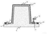
- FIG. 2 is a schematic diagram showing an example of the appearance of the mammography apparatus photographing stand according to the embodiment of the present invention.
- FIG. 3A is a schematic diagram illustrating an example of an opening of the mammography apparatus photographing stand according to the embodiment of the present invention.
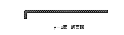
- FIG. 3B is a cross-sectional view showing an example of a cross-sectional shape in the yz plane of FIG.
- FIG. 3C is a schematic diagram illustrating an example of an opening of the imaging table for the mammography apparatus according to the embodiment of the present invention.
- FIG. 1 is a block diagram showing a configuration of a mammography apparatus according to an embodiment of the present invention.
- FIG. 2 is a schematic diagram showing an example of the appearance of the mammography apparatus photographing stand according to the embodiment of the present invention.
- FIG. 3A is a schematic diagram illustrating an example of an opening of the ma
- FIG. 3d is a cross-sectional view showing an example of a cross-sectional shape in the yz plane of FIG.
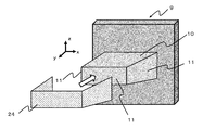
- FIG. 4 is a schematic view showing an example of a single-sided mold for molding a mammography apparatus photographing stand according to an embodiment of the present invention.
- FIG. 5 is a schematic diagram showing an example of a part of the step (I) of the method for manufacturing the photographing stand for the mammography apparatus according to the embodiment of the present invention.
- FIG. 6 is a schematic diagram illustrating an example of a part of the step (I) of the method for manufacturing the imaging table for the mammography apparatus according to the embodiment of the present invention.
- FIG. 7 is a schematic diagram showing an example of a part of the step (I) of the method for manufacturing the photographing stand for the mammography apparatus according to the embodiment of the present invention.
- FIG. 8 a is a schematic diagram illustrating an example of the appearance of the mammography apparatus photographing stand according to the embodiment of the present invention.
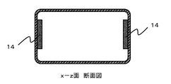
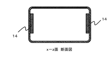
- FIG. 8b is a cross-sectional view showing an example of a cross-sectional shape in the xz plane of FIG. 8a.
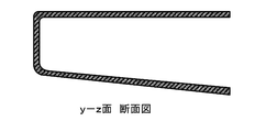
- 8c is a cross-sectional view showing an example of a cross-sectional shape in the yz plane of FIG. 8a.
- FIG. 9 is a schematic diagram illustrating an example of a process (II) of the method for manufacturing the imaging table for the mammography apparatus according to the embodiment of the present invention.
- FIG. 10 is a schematic diagram showing an example of a double-sided mold for molding a mammography apparatus photographing stand according to an embodiment of the present invention.
- FIG. 11 a is a schematic diagram illustrating an example of an appearance of a first member constituting the mammography apparatus photographing stand according to the embodiment of the present invention.
- 11b is a cross-sectional view showing an example of a cross-sectional shape in the yz plane of FIG. 11a.
- FIG. 12 a is a schematic diagram illustrating an example of an appearance of a second member constituting the mammography apparatus photographing stand according to the embodiment of the present invention.
- 12b is a cross-sectional view showing an example of a cross-sectional shape in the yz plane of FIG. 12a.
- FIG. 11 a is a schematic diagram illustrating an example of an appearance of a first member constituting the mammography apparatus photographing stand according to the embodiment of the present invention.
- 11b is a cross-sectional view showing an example of
- FIG. 13A is a schematic diagram illustrating an example of the appearance of a mammography apparatus photographing stand including the first member according to FIG. 11A and the second member according to FIG. 12A.
- FIG. 13B is a cross-sectional view showing an example of a cross-sectional shape in the xz plane of FIG. 13A.
- 13c is a cross-sectional view showing an example of a cross-sectional shape in the yz plane of FIG. 13a.
- FIG. 14 is a schematic diagram illustrating an example of a process of a method for manufacturing a mammography apparatus photographing stand according to an embodiment of the present invention.
- FIG. 15 is a schematic diagram illustrating an example of steps of a method for manufacturing a mammography apparatus photographing stand according to an embodiment of the present invention.
- FIG. 16 is a schematic diagram illustrating an example of a process of a method for manufacturing a mammography apparatus photographing stand according to an embodiment of the present invention.
- FIG. 17A is a schematic diagram illustrating an example of an appearance and a cross-sectional shape of the mammography apparatus photographing stand according to the embodiment of the present invention.
- FIG. 17B is a cross-sectional view showing an example of a cross-sectional shape in the xz plane of FIG. 17A.
- FIG. 17c is a cross-sectional view showing an example of a cross-sectional shape in the yz plane of FIG. 17a.
- FIG. 17A is a schematic diagram illustrating an example of an appearance and a cross-sectional shape of the mammography apparatus photographing stand according to the embodiment of the present invention.
- FIG. 17B is a cross-sectional view showing an example of a cross-sectional shape in the xz plane of FIG. 17A.
- FIG. 17c is a cross-sectional view showing
- FIG. 18 a is a schematic diagram illustrating an example of an appearance of a first member constituting the mammography apparatus photographing stand according to the embodiment of the present invention.
- 18b is a cross-sectional view showing an example of a cross-sectional shape in the yz plane of FIG. 18a.
- FIG. 19A is a schematic diagram illustrating an example of the appearance of the mammography apparatus photographing stand according to the embodiment of the present invention.
- FIG. 19B is a cross-sectional view showing an example of a cross-sectional shape in the xz plane of FIG. 19A.
- FIG. 19c is a cross-sectional view showing an example of a cross-sectional shape in the yz plane of FIG. 19a.
- 20A is a schematic diagram illustrating an example of the appearance of the mammography apparatus photographing stand according to the embodiment of the present invention.
- 20b is a cross-sectional view showing an example of a cross-sectional shape in the xz plane of FIG. 20a.
- 20c is a cross-sectional view showing an example of a cross-sectional shape in the yz plane of FIG. 20a.
- FIG. 21 is a schematic diagram showing an example of the appearance of the mammography apparatus photographing stand according to the embodiment of the present invention.
- 22a is a cross-sectional view showing an example of a cross-sectional shape in the yz plane of FIG. 19a.
- 22b is a cross-sectional view showing an example of a cross-sectional shape in the yz plane of FIG. 19a.
- An imaging table is an imaging table supported in a cantilevered state by an X-ray imaging apparatus, and is a planar body having an opening on a surface connected to the X-ray imaging apparatus. And at least an X-ray irradiation surface of the planar body includes a unidirectional carbon fiber composite material including carbon fibers and a matrix resin aligned in one direction, and the one direction The connecting portion is joined to a region formed of a carbon fiber composite material.
- the application is not limited as long as the X-ray imaging apparatus is supported in a cantilever state, but an imaging table for a mammography apparatus can be exemplified.
- the mammography apparatus is formed by connecting a mammography apparatus imaging stand to the mammography apparatus main body.
- a mammography apparatus imaging stand to the mammography apparatus main body.
- the imaging table for the mammography apparatus uses a unidirectional carbon fiber composite material on at least the X-ray irradiation surface, so that it has a high rigidity compared to a conventional carbon fiber woven composite material, and therefore affects the amount of deflection.
- the flexural rigidity which is a characteristic that gives the value
- the plate thickness can be made thinner than that of the carbon fiber woven composite material. Therefore, the attenuation of the X-ray intensity until it passes through the mammography apparatus imaging table and reaches the internal X-ray detector is reduced, that is, the X-ray permeability is improved, so that the exposure dose of the subject is reduced. Can do.
- the plate thickness here is the plate thickness of the X-ray irradiated surface that contributes to X-ray transmission, and is preferably 0.5 mm or more and 5.0 mm or less. More preferably, it is 0.8 mm or more and 3.5 mm or less. The range which combined any of said upper limit and lower limit may be sufficient.
- the plate thickness is less than 0.5 mm, the rigidity as a photographing stand cannot be ensured, and there is a possibility that the plate is easily deformed during photographing.
- the plate thickness is thicker than 5.0 mm, the X-ray transmission is inferior, so that it is necessary to increase the X-ray irradiation intensity, which may increase the exposure dose of the subject in one imaging.
- the main body of the mammography apparatus includes an X-ray generation unit and a compression plate. Examples of the arrangement thereof include an embodiment as shown in FIG.
- the mammography apparatus photographing stand 1 according to the embodiment of the present invention is supported by the mammography apparatus main body 2 in a cantilever state.
- the mammography apparatus shown in FIG. 1 includes a mammography apparatus main body 2, a mammography apparatus imaging table 1, a compression plate 3, and an X-ray generation unit 4.
- the mammography apparatus imaging table 1 includes an X-ray irradiation surface 5 and a bottom surface. 6 is provided.
- the imaging table 1 for mammography apparatus is formed by a planar body having a sufficiently long side forming a surface rather than a plate thickness, and is generally a box having a hollow inside.
- the shape of the mold, and an X-ray detector is often provided inside.
- Such an X-ray detector may be directly connected to the mammography apparatus main body, or may be fixed in the imaging table and connected to the mammography apparatus main body 2 by wiring.
- the said X-ray irradiation surface is a plane area
- the planar region may be the entire top surface of the imaging table or a part thereof, but from the viewpoint of X-ray transmission and rigidity, the X-irradiated surface is formed of a carbon fiber composite material. Moreover, the X-ray irradiation surface may further contain a resin sheet. More preferably, a stepped portion is provided in the top surface region other than the X-ray irradiation surface. By providing such a shape, since the step portion functions as a standing wall, it is possible to suppress deflection due to the load of the compression plate during mammography photography. In addition, the area for storing the X-ray detector and the like in the imaging table can be expanded. An example of the position where the step portion is provided is the device connection surface (FIG. 21).
- the imaging stand for the mammography apparatus is lighter on the inner layer side than the skin material having the carbon fiber composite material, as compared with the structure formed by the carbon fiber composite material alone by adopting the above-described configuration. Since the resin sheet is disposed, the attenuation of the X-ray intensity until it passes through the mammography apparatus imaging table and reaches the internal X-ray detector is suppressed, that is, the X-ray permeability is improved. Can be reduced. In addition, since the carbon fiber composite material including continuous fibers forms the skin material, most of the load that is exposed during photographing can be handled by the highly rigid skin material. Therefore, the X-ray transparency can be improved while maintaining rigidity.
- At least the X-ray irradiation surface in the planar body is formed by a sandwich structure in which a skin material having a carbon fiber composite material is disposed on both surfaces of a core material including a resin sheet.
- the structure of the planar body may be a canape structure in which the skin material exists only on one side of the outermost surface, or a sandwich structure in which the skin material exists on both sides of the imaging table surface, but it has high rigidity and high X-ray permeability. From the viewpoint of achieving, a sandwich structure in which the X-ray irradiation surface has a skin material made of a carbon fiber composite material and a core material made of a resin sheet is preferable.
- the bending stiffness that affects the amount of deflection increases as the plate thickness increases, and the amount of deflection can be reduced.
- the plate thickness is simply increased, from the viewpoint of X-ray transparency. It will be disadvantageous.
- High X-ray permeability and high rigidity can be achieved by using a resin sheet having excellent X-ray permeability as a core material as in the present invention.
- the carbon fiber composite material forming the X-ray irradiated surface has a specific bending elastic modulus represented by Eb 1/3 ⁇ ⁇ ⁇ 1 of 2.50 or more when the bending elastic modulus is Eb and the density is ⁇ . It is preferable.
- the specific bending elastic modulus of the carbon fiber composite material is 2.50 or more, the bending elastic modulus is relatively high and the density is low, so that it is difficult to deform and high X-ray permeability is maintained in a well-balanced manner. It is preferable.
- the upper limit value of the specific flexural modulus is not particularly limited, but is preferably 20.00 or less because the balance between the effect of improving X-ray permeability and the flexural modulus is excellent.
- the carbon fiber composite material includes carbon fibers of a continuous fiber and a matrix resin, and examples of the form of the continuous fiber include a woven form in which a woven structure is formed of continuous fibers and a form in which continuous fibers are aligned in one direction.
- a form of continuous fibers these may be used singly or in layers, and the two types may be stacked.
- a continuous fiber means what bundled the fiber bundle in the continuous state, without cut
- the short fiber refers to a fiber having a length of 100 mm or less.
- the skin material may be formed in combination with a form in which discontinuous fibers are arranged in one direction or a form in which discontinuous fibers are dispersed.
- the imaging table for the mammography apparatus may further include a carbon fiber woven composite material including a carbon fiber woven fabric and a resin in addition to the unidirectional carbon fiber composite material.
- a carbon fiber woven composite material including a carbon fiber woven fabric and a resin in addition to the unidirectional carbon fiber composite material.
- the outermost layer of the carbon fiber composite material preferably includes a carbon fiber fabric composite material including a carbon fiber fabric and a resin. Increasing the proportion of carbon fiber woven composite material tends to facilitate shape forming. On the other hand, the X-ray irradiated surface, which is thin and highly rigid, should contain unidirectional carbon fiber composite material and increase the proportion. Therefore, it becomes easy to achieve the improvement of the characteristics.
- the mammography apparatus may have a gently curved surface from the viewpoint of design, or a subject may have a handle for maintaining a posture during photographing.
- the imaging table for the mammography apparatus also relieves pain when the subject touches, so that the X-ray irradiation surface related to mammography imaging and the corner of the standing wall surface (standing wall surface facing the mammography device body) that contacts the subject (X-ray)
- the design may have a gentle curved surface except for a portion that is bent from the irradiated surface.
- the carbon fiber composite material is included in the outermost layer of the carbon fiber composite material.
- a carbon fiber woven composite material is included in the outermost layer of the planar body.
- the carbon fiber fabric composite material has unidirectional carbon fibers with carbon fiber fluff. Compared to the composite material, it is hard to raise, and the stimulus given to the subject is alleviated. From this viewpoint, an embodiment in which the outermost layer on the X-ray irradiation surface is formed of a carbon fiber woven composite material and the unidirectional carbon fiber composite material is disposed on the inner layer is particularly preferable.
- the carbon fiber composite material according to the embodiment of the present invention includes carbon fibers and a matrix resin.
- carbon fibers such as a polyacrylonitrile (PAN) type
- PAN-based carbon fibers are more preferable from the viewpoint of the balance between strength and elastic modulus of the obtained carbon fiber composite material.
- the strand elastic modulus of the carbon fiber is preferably 200 GPa or more, more preferably 220 GPa or more, and further preferably 240 GPa or more. When the strand elastic modulus of the carbon fiber is less than 200 GPa, desired characteristics may not be obtained when the carbon fiber composite material is used.
- thermosetting resin Either a thermosetting resin or a thermoplastic resin can be used.
- the matrix resin is a thermosetting resin
- the thermosetting resin is cured by heating at the time of molding and, if necessary, by further heating to a temperature at which the thermosetting resin is cured after molding. It becomes.
- the matrix resin is a thermoplastic resin
- the matrix resin is obtained by cooling and solidifying the resin melted by heating during molding.
- the thermosetting resin include an epoxy resin, a vinyl ester resin, a phenol resin, an unsaturated polyester resin, and the like. Any thermosetting resin may be used as long as it causes a crosslinking reaction by heat and forms at least a partial three-dimensional crosslinked structure.
- a prepreg As a shaping
- thermoplastic resins polypropylene resin, polyethylene resin, polyamide resin, polyester resin, polyarylene sulfide resin, polyphenylene sulfide resin, polyether ketone resin, polyether ether ketone resin, polyether ketone ketone resin, polyether sulfone resin, polyimide Resins, polyamideimide resins, polyetherimide resins, and polysulfone resins are preferably used, and cyclic oligomers that are precursors of any of these resins are also preferably used. Among them, it is preferable to select a resin excellent in chemical resistance in view of cleaning with a disinfecting solution or the like from the viewpoint of operating the imaging table for the mammography apparatus.
- the unidirectional carbon fiber composite material according to the embodiment of the present invention includes a layer containing carbon fibers and a matrix resin aligned in one direction, and is a laminate in which two or more layers are laminated even if the layer is composed of one layer. You may be comprised from a state.
- the orientation direction of the carbon fibers may be arbitrarily shifted. From the viewpoint of yield when cutting out a material from a sheet-like substrate, a laminated structure in which the orientation directions of the carbon fibers are shifted by 90 ° is preferable.
- the carbon fiber woven composite material according to the embodiment of the present invention includes a sheet-like material woven from carbon fibers and a matrix resin, and usually has a layer structure and is composed of one layer, You may be comprised from the lamination
- the carbon fiber woven structure include plain weave, twill weave, and satin weave. Among these, twill weave is preferable from the viewpoint of shape followability and X-ray permeability.
- the material constituting the resin sheet according to the embodiment of the present invention may be either a thermosetting resin or a thermoplastic resin, and is not particularly limited as long as the density is lower than that of the carbon fiber composite material.
- the thermosetting resin include epoxy resin, vinyl ester resin, phenol resin, thermosetting polyimide resin, polyurethane resin, urea resin, melamine resin, bismaleimide resin, acrylic resin, and the like.
- a copolymer of epoxy resin and a thermosetting resin, a modified product, and a resin blended with two or more types can also be used.
- thermoplastic resins polypropylene resin, polyethylene resin, polycarbonate resin, polyamide resin, polyester resin, polyarylene sulfide resin, polyphenylene sulfide resin, polyether ketone, polyether ether ketone resin, polyether ketone ketone resin, polyether sulfone resin , Polyimide resin, polyamideimide resin, polyetherimide resin, polysulfone resin, polystyrene resin, acrylonitrile-butadiene-styrene (ABS) resin, polyvinyl chloride resin, polymethacrylamide resin, and any of these resins Cyclic oligomers that are precursors are also preferably used.
- fillers such as carbon fiber and glass fiber
- fillers may be included from a viewpoint of improving a dynamic characteristic.
- a thermosetting resin if it is subjected to molding in an uncured state, it may flow and cannot be molded. Therefore, a cured sheet molded in a desired shape in advance is preferable. From the viewpoint of moldability, since the shape can be followed by heat, a resin sheet made of a thermoplastic resin is preferably used. Moreover, even if it is a resin sheet which uses a thermoplastic resin as a material, the sheet
- the resin sheet which concerns on embodiment of this invention contains the discontinuous reinforcement fiber disperse
- the fiber bundle of discontinuous reinforcing fibers can be obtained by dispersing the discontinuous reinforcing fibers in a substantially monofilament shape in addition to the effect of improving the mechanical properties as compared with the case where the resin sheet is formed by a single resin. Since the weak part at the end can be minimized, excellent reinforcing efficiency is exhibited. Also, by discontinuously dispersing discontinuous reinforcing fibers, mechanical isotropy is manifested, so performance changes due to misplacement assumed at the time of molding do not substantially occur, and product reliability is improved. .
- the term “substantially monofilament” means that a single yarn of discontinuous reinforcing fibers exists in less than 500 fineness strands.
- the single yarn diameter of the discontinuous reinforcing fibers is preferably 20 ⁇ m or less, and more preferably 10 ⁇ m or less, from the viewpoint of reflection in an X-ray fluoroscopic image.
- the single yarn diameter is thicker than 20 ⁇ m, there is a possibility of affecting the reflection in the X-ray fluoroscopic image.
- the kind of discontinuous reinforcing fiber is not particularly limited, but carbon fiber is preferable from the viewpoint of X-ray permeability and reinforcing effect.
- the resin sheet according to the embodiment of the present invention is preferably composed of resin, discontinuous reinforcing fibers, and voids.
- void refers to a space formed by discontinuous reinforcing fibers coated with a resin as a columnar support and overlapping or intersecting.
- gap in a resin sheet exists in the range of 10 volume% or more and 99 volume% or less.
- the volume content rate makes the sum total of each volume content rate of resin, discontinuous reinforcement fiber, and space
- the boundary between the skin material and the resin sheet according to the embodiment of the present invention may include an adhesive layer from the viewpoint of increasing the strength of the imaging table for the mammography apparatus.
- an adhesive layer can illustrate the form which forms an adhesive layer using an adhesive after producing a skin material and a resin sheet separately, it is preferable to form an adhesive layer during shaping
- a method of forming an adhesive layer during molding when the matrix resin species of the skin material and the resin species of the resin sheet are the same, the mutual resin can flow during molding to form an adhesive layer.
- a method of forming the adhesive layer by inserting a base material that forms the adhesive layer can be exemplified.
- a base material which forms an adhesive layer it can select arbitrarily from the resin seed
- the matrix resin of the skin material is an epoxy resin and the resin sheet is a polypropylene resin
- the nonwoven fabric forms an anchoring structure with the epoxy resin during molding, and the polypropylene resin derived from the nonwoven fabric partially melts and adheres to the polypropylene resin of the resin sheet. Can be formed.
- the resin sheet according to the embodiment of the present invention is a foam material.
- the foam material according to the embodiment of the present invention is a foam material made of closed cells.
- the closed cell refers to a state in which bubbles existing inside are not connected to each other and are partitioned by a wall. Since the bubbles are not connected to each other, the matrix resin of the skin material can be prevented from soaking into the voids of the foam material during molding, and the variation in X-ray transmission characteristics obtained at an arbitrary point is reduced, which is preferable.
- the closed cell foam cell of the foam material according to the embodiment of the present invention has a ratio of the major axis to the minor axis (minor axis / major axis) of 0.25 to 0.90. This is preferable from the viewpoint of improving the mammography image obtained by improving the denseness.
- the (minor axis / major axis) represented by the ratio of the major axis to the minor axis is more preferably 0.30 to 0.80, and still more preferably 0.35 to 0.75. The range which combined any of said upper limit and lower limit may be sufficient.
- the ratio of the major axis to the minor axis is preferably such that the average minor axis of the closed cell foam cell is 25 to 250 ⁇ m, more preferably 25 to 225 ⁇ m, and still more preferably. 50 to 200 ⁇ m.
- the range which combined any of said upper limit and lower limit may be sufficient. In this range, in addition to suppressing the penetration of the matrix resin contained in the skin material into the foam material, the matrix resin penetrates from the skin material to the foam material, so that the matrix resin of the skin material is insufficiently formed. This is preferable because surface irregularities can be suppressed.
- the average minor axis is long, the interval between the walls forming the closed cells becomes long, so that it may be difficult to suppress the penetration of the matrix resin.
- the ratio of the major axis to the minor axis is defined by a value obtained by dividing the minor axis of the closed cell by the major axis, and an arbitrary cross section in the region including the foam material of the imaging table for the mammography apparatus is observed.
- the length of the minor axis is measured, the minor axis in the same closed cell is calculated by dividing by the major axis, and an average value is obtained. More specifically, a sample in which a small piece is arbitrarily cut out from the area of the plane portion of the X-ray irradiation surface of the mammography apparatus imaging stand, embedded in an epoxy resin, and then the cross section in the thickness direction of the X-ray irradiation surface is polished. Prepare and observe the sample at a magnification of 100 using a laser microscope, measure the length of the major axis and minor axis for each of the 50 closed cells visible in the observed image range, and calculate the average value And get.
- the minor axis of the closed cell is substantially parallel to the thickness direction of the imaging table.
- a uniform bubble structure in which the minor axis is aligned in the thickness direction is taken. Therefore, variation in the weight distribution in the thickness direction at any point on the X-ray irradiation surface is reduced, and unevenness in the photographed image is caused. Since it can suppress, it is preferable.
- substantially parallel indicates that the angle with respect to the axis in the thickness direction is within ⁇ 30 °.
- the angle with respect to the axis in the thickness direction is the same as that of [Measurement of ratio between major axis and minor axis of closed cells (minor axis / major axis)], and the sample is observed at a magnification of 100 using a laser microscope.
- the inclination of the minor axis with respect to the thickness direction axis is measured, and the average value is calculated.
- An imaging table for a mammography apparatus usually has a mechanism that is supported in a cantilevered state by the mammography apparatus, and preferably in a region formed of the carbon fiber composite material.
- a connecting member connectable to the mammography apparatus main body is provided.
- a connecting member that can be connected to the main body of the mammography apparatus is provided in an area formed by the planar body. That is, a mode in which a portion to which the connecting member is attached is provided in the region, and the connecting member is attached to the portion.
- the position where the connecting member is attached is not particularly limited as long as it is within the region formed of the carbon fiber composite material or the region of the planar body, but from the viewpoint of the design of the mammography apparatus photographing stand obtained, the carbon fiber composite
- An inner wall of material or an inner wall of a planar body is preferred. More preferably, it is an inner wall of two side surfaces in a surface having an opening to be described later.
- connection member can be exemplified by fixing the connection member to the mammography apparatus.
- the imaging table for a mammography apparatus includes a first member that forms the X-ray irradiation surface and a second member that forms a bottom surface facing the X-ray irradiation surface. preferable.
- a unidirectional carbon fiber composite material or a resin sheet is used, the material does not follow the shape at the time of molding, and there is a problem that it is difficult to mold a complicated shape such as a hollow box shape.
- the imaging stand according to the embodiment of the present invention may have third and fourth members separately.
- the material of the second member may be the same material as the first member or may be composed of only a carbon fiber woven composite material, but is at least one selected from the group of metals, plastics, and elastomers. It is preferable. By making the second member such a material, it is possible to separate the function of ensuring X-ray transparency and the function of imparting the shape of the subject's handle, etc., and maintaining the functions necessary for conventional mammography devices. However, it is preferable because a complicated shape can be easily designed with good productivity.
- a metal is preferably used from the viewpoint of workability and dimensional accuracy, and types thereof include aluminum, copper, nickel, tin, iron, magnesium, chromium, tungsten, zinc, lead, and the like. These alloys can be exemplified.
- the material of the second member may be composed of one type of metal material, or may be a combination of two or more types of metals.
- plastic is preferably used from the viewpoint of moldability / workability and manufacturing cost, and either a thermosetting resin or a thermoplastic resin can be used.
- thermosetting resin examples include an epoxy resin, a vinyl ester resin, a phenol resin, a polyurethane resin, a urea resin, and a melamine resin.
- thermoplastic resin examples include polypropylene resin, polyethylene resin, polycarbonate resin, polyamide resin, polyester resin, polyarylene sulfide resin, polyphenylene sulfide resin, and cyclic oligomers that are precursors of any of these resins.
- the material of the second member may be a plastic containing a filler such as glass fiber.
- the material of the second member is preferably an elastomer, and examples thereof include silicone rubber, urethane rubber, and thermoplastic elastomer.
- the shape of the first member is not particularly limited as long as the X-ray irradiation surface is included, but preferably has a top surface including the X-ray irradiation surface and stands on the outer periphery of the top surface including the X-ray irradiation surface.
- a shape having a wall is also preferred. Since the first member has the standing wall portion, deformation due to a load received from the compression plate 3 at the time of mammography photography can be suppressed.
- the shape of the second member can be exemplified as a shape suitable for constituting a region other than the region constituted by the first member in the mammography apparatus imaging stand, and a bottom surface facing the X-ray irradiation surface and its A shape having a standing wall portion standing on the outer periphery is preferable.
- the imaging table includes a first member that forms a top surface including an X-ray irradiation surface, and a second member that forms a bottom surface facing the X-ray irradiation surface and a standing wall portion standing on the outer periphery thereof. It is preferable.
- the height of the standing wall in the first member is preferably 10 mm or more.
- the first member can take a large space for storing the X-ray detector.
- the height of the standing wall is a distance in the vertical direction from the top surface to the edge of the standing wall. Further, the height of the standing wall is more preferably 20 mm or more, and particularly preferably 30 mm or more.
- the imaging table for the mammography apparatus has a connection surface connected to the mammography apparatus main body, and has an opening on the connection surface. good.
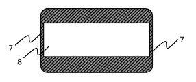
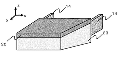
- the mammography apparatus photographing stand 1 shown in FIG. 2 has a standing wall portion 7 and has an opening on a connection surface (mammography apparatus main body side) connected to the mammography apparatus main body.
- the opening 8 may be one in which all of the connection surface connected to the mammography apparatus main body is opened, and as shown in FIGS. 3c and 3d, a part of the connection surface is formed. It may be opened.
- each of the connecting members is preferably joined to two standing wall portions 7 that face each other on the surface having the opening 8.
- An example of the joining position of the third member is the inner wall side of the surface with which the subject contacts (FIG. 17).
- a 3rd member plays the role of a reinforcement member and rigidity improves, the opening which arises in the standing wall part edge part of a 1st member and the 2nd standing wall part edge part is suppressed. This improves the position accuracy during shooting.
- corrugation does not exist in the area
- the form is not particularly limited as long as the boundary line between the first member and the second member does not exist on the facing surface of the apparatus connection surface.
- the length of the standing wall located on the facing surface of the device connection surface in the first member Extending to the height of the standing wall of the second member and joining the first member so as to cover the standing wall of the second member (FIG. 22a), or the device connection surface in the second member
- the length of the standing wall located on the opposite side of the first member is extended to the height of the first member standing wall, and the second member standing wall is connected so as to cover the first member standing wall (FIG. 22b). it can.
- the manufacturing method of the mammography apparatus photographing stand preferably includes the following steps (I) to (II).
- Step (I) is a step in which a prepreg is arranged in a single-sided form as a base material containing carbon fibers (A) made of continuous fibers and a thermosetting resin (B).
- the thermosetting resin (B) in the prepreg is preferably in a semi-cured state having excellent tackiness because it needs to be pressure-bonded to each other and the mold surface during lamination.
- an epoxy resin is preferable in consideration of tackiness in the attaching process and mechanical properties when formed into a molded product.
- molding one layer at a time on the surface of a single-sided type and the method of shape
- Step (II) is a step of covering and heating the region including the single-sided mold and the prepreg with the flexible film 16 and heating and pressurizing the space formed by the single-sided mold 9 and the flexible film 16 under reduced pressure ( FIG. 9).
- a valve 19 is installed as a suction port on a part of the contact surface between the flexible film 16 and the single-sided mold 9, and a vacuum is used to form a molding space (single-sided type and flexible one from the suction port).
- the air present in the space made up of the film is sucked to decompress the molding space.
- the molding space is in a reduced pressure state from the outside, the shaped prepreg itself is in a pressurized state. Further, at this time, from the viewpoint of forming a good design surface, it is preferable to adopt a mode in which a die having a shape corresponding to the single-sided die is pressed.
- the mold is pressed so as to be in close contact with the prepreg surface and then covered with a flexible film together with the mold, or the single-sided mold and the prepreg
- An example is a method in which a region including is covered with a flexible film, and the space formed by the single-sided mold and the flexible film is decompressed, and then the mold is pressed from above the flexible film. Then, by putting it in an autoclave, a hot air oven or the like and heating it, the curing reaction of the thermosetting resin (B) proceeds to obtain a mammography apparatus photographing stand.
- the gas existing in the molding space is sucked and depressurized, so the air between the shaped prepreg layers and the air between the prepreg and the single-sided surface is also removed, and the resulting mammography apparatus imaging stand Void formation is suppressed, and there is an effect of having good mechanical properties and surface quality. Furthermore, it is preferable to perform heating and pressurization in an autoclave because the formation of voids is further suppressed. More preferably, in the step (I), it is preferable that the substrate is shaped into a single-sided mold by an automatic laminating apparatus.
- a unidirectional carbon fiber composite material requires a process of cutting into a complicated shape in advance so that a large-sized base material can be formed without any problems.
- an automatic laminating device it is possible to form a single-sided mold with a narrow width without using a cutting process. Since variation can also be reduced, it is preferable.
- unidirectional carbon fiber prepreg As a unidirectional carbon fiber prepreg, “Torayca (registered trademark) prepreg” P3252S-10 manufactured by Toray Industries, Inc. was prepared.
- Carbon fiber fabric prepreg As a carbon fiber fabric prepreg, “Torayca (registered trademark) prepreg” F6347B-05P manufactured by Toray Industries, Inc. was prepared.
- the aluminum equivalent is preferably 0.5 mmAL or less at any point regardless of the conditions of the X-ray irradiation tube voltage, and the X-ray irradiation tube voltage is 20 kV to 60 kV.
- the X-ray irradiation tube voltage may be 20 kV or 60 kV and 0.5 mmAL or less.
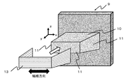
- Example 1 12 layers of unidirectional carbon fiber prepregs 13 were laminated on the single-sided mold 9 shown in FIG.
- the single-sided mold 9 includes an A surface 10 that forms the top surface including the X-ray irradiation surface, three surfaces (B surface 11) that form the standing wall on the side surface of the imaging table 1A for the mammography apparatus, and an imaging table 1A for the mammography apparatus. And a C surface 12 that forms the bottom surface of.
- the step of forming the unidirectional carbon fiber prepreg 13 on the single-sided die 9 was carried out by a method of laminating the single-sided die 9 on each surface of the single-sided die 9 one by one.
- the unidirectional carbon fiber prepreg 13 is laminated on the B surface 11 (FIG. 5), and then the unidirectional carbon fiber prepreg 13 is laminated on the A surface 10 and the C surface 12 in a laminated configuration [0/90] 3S. (FIG. 6) Finally, the unidirectional carbon fiber prepreg 13 was laminated on the B surface 11 (FIG. 7).
- the x direction shown in FIG. 5 coincides with the 0 ° direction.
- [0/90] indicates that two layers are laminated so that the fiber orientation directions of the unidirectional carbon fiber prepreg 13 are the 0 ° direction and the 90 ° direction.
- the subscript 3S indicates that the two layers are repeated three times and further symmetrically stacked. Therefore, it means that a total of 12 unidirectional carbon fiber prepregs 13 are laminated.
- the cutting pattern of the unidirectional carbon fiber prepreg 13 in the present laminated structure includes a cutting pattern laminated on the B surface 11 and a 0 ° direction cutting pattern laminated on the A surface 10 and the C surface 12 (the carbon fibers are oriented in the x direction).
- a valve 19 having a backflow prevention valve as a suction port on the bleeder 17
- the single-sided mold was covered with the flexible film 16, and the sealing material 18 and the flexible film 16 were brought into close contact with each other.
- a vacuum pump is connected to the valve 19 which is a suction port, and air in a molding space (a space including a region where the unidirectional carbon fiber prepreg 13 formed by a single-sided mold and a flexible film 16 is laminated).
- a molding space a space including a region where the unidirectional carbon fiber prepreg 13 formed by a single-sided mold and a flexible film 16 is laminated.
- a single-sided mold is put into the autoclave apparatus, heated at a rate of 2.5 ° C./min under the condition of a pressure of 3 atm, and held for 90 minutes after reaching 130 ° C. to heat and pressurize the prepreg.
- the thermosetting resin composition in 13 was cured.
- the molded product was removed from the single-sided mold 9,
- the obtained mammography apparatus photographing stand 1A (FIGS. 8a, 8b and 8c) has an opening 8, and an aluminum alloy connecting member 14 is inserted through the opening to form an opening 2 which faces each other.
- a two-component epoxy adhesive (FIGS. 8a and 8b)
- the X-ray irradiation tube voltage was 60 kV, and the conditions were 0.17 mmAL and 20 kV. And was 0.14 mmAL.
- a rectangular test piece was cut out using an NC router, and the specific bending elasticity calculated by the method described in [Calculation of specific bending elastic modulus] above. The rate was 2.70.
- the thickness of the A surface (X-ray irradiation surface 5) of the obtained mammography apparatus photographing stand 1A was 1.28 mm.
- Example 2 A unidirectional carbon fiber prepreg 13 was laminated by using the same single-sided die as in Example 1 and setting the laminated structure to [0/90/0/90/0/0/90/0/90/0] from the die surface side. Thereafter, a mammography apparatus photographing stand 1B was obtained in the same manner as in Example 1 except that one carbon fiber woven prepreg was laminated on the outermost layers of all of the A surface 10, the B surface 11, and the C surface 12. . The obtained mammography apparatus photographing stand 1B has an opening 8, and a joining member 14 made of an aluminum alloy is joined in the same manner as in (Example 1) (FIGS. 8a, 8b and 8c).
- the aluminum equivalent of the A surface (X-ray irradiation surface 5) was measured.
- the X-ray irradiation tube voltage was 60 kV, 0.18 mmAL, and 20 kV, 0.15 mmAL. It was.
- Example 2 the specific bending elastic modulus obtained in the same manner as in Example 1 for the obtained mammography apparatus photographing stand 1B was 2.75. Moreover, the thickness of the A surface (X-ray irradiation surface 5) of the obtained imaging table 1B for mammography apparatuses was 1.30 mm.
- the unidirectional carbon fiber prepreg 13 was laminated with a laminated configuration [0/90] 3S to obtain a prepreg laminate 15.
- the prepreg laminate 15 has a square shape, and the unidirectional carbon fiber prepreg 13 has one cutting pattern. Therefore, there was little waste such as scraps.
- the laminate 15 is arranged in a pair of double-sided molds of a female mold 20 and a male mold 21 shown in FIG. 10, and heated and pressurized at 130 ° C. for 90 minutes at a surface pressure of 1.0 MPa using a hydraulic press machine, A molded product was obtained. The surface pressure was calculated from the area of the laminate before molding (projected area viewed from the lamination direction).
- the standing wall surface is trimmed with an NC router so that the x direction in FIG. 11a coincides with the 0 ° direction, and each of the A surface 10 and the B surface 11 erected on the three outer sides thereof.
- a carbon fiber composite material member 22a (first member 22) forming a part was obtained (FIGS. 11a and 11b).
- an ABS resin (“Toyolac (registered trademark)" 600-309, manufactured by Toray Industries, Inc.) is formed into a 3 mm thick resin sheet by extrusion molding, and the outer periphery 3 A molded product with a standing wall surface was obtained.
- Resin member which processes the standing wall surface of the molded product with an NC router forms part of each of C surface 12 and B surface 11 erected on the three outer sides thereof, and has a stepped portion on the B surface 11 side 23a (second member 23) was obtained (FIGS. 12a and 12b).
- the carbon fiber composite material member 22a and the resin member 23a are joined at the stepped portion as shown in FIGS.
- the obtained imaging stand 1C for mammography apparatus has an opening 8 on one side, and a joining member 14 made of aluminum alloy is joined in the same manner as in (Example 1), assembled to the mammography apparatus main body 2, and further When a mammography image was taken, a good image could be obtained.
- the aluminum equivalent of the A surface was measured.
- the X-ray irradiation tube voltage was 60 kV, 0.17 mAL, and 20 kV, 0.14 mmAL. It was.
- required similarly to (Example 1) about the obtained imaging stand 1C for mammography apparatuses was 2.71.
- the thickness of the A surface (X-ray irradiation surface 5) of the obtained imaging table 1C for mammography apparatuses was 1.28 mm.
- Example 4 A unidirectional carbon fiber prepreg 13 is laminated in a laminated configuration [0/90/0/90/0/0/90/0/90/0], and a single layer of carbon fiber woven prepreg is laminated on one side of the laminate. 15 was obtained.
- a carbon fiber composite material member 22b (first member 22) was obtained in the same manner as in Example 3 except that the carbon fiber woven prepreg surface was brought into contact with the female mold surface and heated and pressurized with a double-sided mold.
- a polycarbonate resin ("Iupilon (registered trademark)" E-2000, manufactured by Mitsubishi Engineering Plastics Co., Ltd.) is molded into a 3 mm thick resin sheet by extrusion molding, and the resin sheet is vacuum molded. A molded product having three standing walls was obtained.
- Resin member which processes the standing wall surface of the molded product with an NC router forms part of each of C surface 12 and B surface 11 erected on the three outer sides thereof, and has a stepped portion on the B surface 11 side 23b (second member 23) was obtained.
- the carbon fiber composite material member 22b and the resin member 23b are joined at the stepped portion as shown in FIGS. 13a, 13b, and 13c using a two-component epoxy adhesive, and the photographic stand 1D for mammography apparatus Got.
- the mammography apparatus photographing stand 1D has an opening 8, and a joining member 14 made of an aluminum alloy is joined in the same manner as in (Example 1) (FIGS. 13a, 13b and 13c), and the mammography apparatus body 2 When a mammography image was further photographed, it was possible to obtain a good image.
- the aluminum equivalent of surface A (X-ray irradiation surface 5) was measured.
- the X-ray irradiation tube voltage was 60 kV, 0.18 mAL, and 20 kV, 0.15 mmAL. It was.
- photography stand 1D for mammography apparatuses was 2.75.
- the thickness of the A surface (X-ray irradiation surface 5) of the obtained imaging table 1D for mammography apparatuses was 1.30 mm.
- Example 5 The unidirectional carbon fiber prepreg 13 was cut into a width of 10 mm with the longitudinal direction and the fiber orientation direction being matched to obtain a unidirectional carbon fiber tape.
- the unidirectional carbon fiber tape is set in an automatic laminating apparatus, and using the same single-sided mold 9 as in Example 1, [0/90] 3S from the mold surface side, and using an automatic laminating apparatus, shaping is performed. did.
- the shaping step the unidirectional carbon fiber tape was shaped with a uniform thickness at the corners without forming a seam on the standing wall surface. Otherwise, a mammography apparatus photographing stand 1E was obtained in the same manner as in (Example 1).
- the mammography apparatus photographing stand 1E has an opening 8, and an aluminum alloy connecting member 14 is joined in the same manner as in the first embodiment (FIGS. 8a, 8b, and 8c), and is attached to the mammography apparatus body 2.
- FIGS. 8a, 8b, and 8c first embodiment
- the aluminum equivalent of surface A (X-ray irradiation surface 5) was measured.
- the X-ray irradiation tube voltage was 0.17 mmAL under 60 kV conditions and 0.14 mmAL under 20 kV conditions. It was.
- photography stand 1E for mammography apparatuses obtained was 2.68.
- the thickness of the A surface (X-ray irradiation surface 5) of the obtained mammography apparatus photographing stand 1E was 1.28 mm.
- a mammography apparatus photographing stand 1F was obtained in the same manner as in (Example 1) except that the carbon fiber fabric prepreg 7 layers were used for shaping into a mold.
- the mammography apparatus imaging stand 1F has an opening 8, and a connecting member 14 made of an aluminum alloy is joined in the same manner as in (Example 1) (FIGS. 8a, 8b and 8c), and is attached to the mammography apparatus body 2.
- a connecting member 14 made of an aluminum alloy is joined in the same manner as in (Example 1) (FIGS. 8a, 8b and 8c), and is attached to the mammography apparatus body 2.
- the X-ray irradiation tube voltage was 60 kV, 0.20 mmAL, and 20 kV, 0.16 mmAL. It was. Moreover, the specific bending elastic modulus calculated
- Table 1 summarizes the characteristics of the imaging table for mammography devices obtained in the above-described examples and comparative examples. It was confirmed that the mammography apparatus imaging stand 1A is a mammography apparatus imaging stand that has a thinner X-ray irradiation surface and higher rigidity and X-ray permeability than the mammography apparatus imaging stand 1F. Further, after the surfaces of the mammography apparatus photographing stand 1A and the mammography apparatus photographing stand 1B were polished with sandpaper to expose the carbon fiber, the surface was traced with bare hands, and the mammography apparatus photographing stand 1A was made of carbon fiber fluff. However, no pain was felt on the mammography apparatus photographing stand 1B.
- the mammography apparatus imaging stand 1C has the same rigidity and X-ray transparency as compared with the mammography apparatus imaging table 1A, but can reduce the cutting pattern of the base material and can be manufactured with high productivity. did it.
- the mammography apparatus imaging stand 1E was able to be manufactured with high productivity by automating the single-sided lamination process as compared with the mammography apparatus imaging table 1A.
- Example 11 As a resin sheet, an acid-modified polypropylene resin (“Admer (registered trademark)” QB510, manufactured by Mitsui Chemicals, Inc.) was used to obtain a resin sheet having a thickness of 1.2 mm using an extruder.
- the resin sheet 25 and the carbon fiber fabric prepreg 24 were laminated on the single-sided mold 9 shown in FIG.
- the single-sided mold 9 includes an A surface 10 that forms the top surface including the X-ray irradiation surface, three surfaces (B surface 11) that form the standing wall on the side surface of the imaging table 1A for the mammography apparatus, and an imaging table 1A for the mammography apparatus. And a C surface 12 that forms the bottom surface of.
- the step of forming the carbon fiber woven prepreg 24 and the resin sheet 25 on the single-sided die 9 was performed by a method of laminating the single-sided die 9 one by one.
- the carbon fiber fabric prepreg 24 is laminated on the B surface 11 (FIG. 14), and then the carbon fiber fabric prepreg 24 is formed on the A surface 10 and the C surface 12, respectively, and the carbon fiber fabric prepreg 2 layers are formed on the A surface 10.
- the resin sheet 25 has the same size as the A surface.
- the cutting pattern of the carbon fiber fabric prepreg 24 in the present laminated configuration includes three types of cutting patterns that are stacked on the A surface 10, a cutting pattern that is stacked on the B surface 11, and a cutting pattern that is stacked on the C surface 12.
- the outer periphery of the region where the carbon fiber woven prepreg 24 is laminated is covered with a sealing material 18 (the flexible film 16 and the mold are brought into close contact with each other and the inside of the mold is sealed), and then the prepreg laminated body 15 A bleeder 17 (acting as a spacer for air passage) made of a thick non-woven fabric was disposed on the outer periphery.
- a valve 19 having a backflow prevention valve as a suction port on the bleeder 17
- the single-sided mold was covered with the flexible film 16, and the sealing material 18 and the flexible film 16 were brought into close contact with each other.
- a vacuum pump is connected to the valve 19 which is a suction port, and a molding space (a space including a region in which a carbon fiber woven prepreg 24 and a resin sheet 25 formed from a single-sided mold and a flexible film 16 are laminated). The inside air was sucked to reduce the pressure in the molding space.
- a single-sided mold is put into the autoclave apparatus, heated at a rate of 2.5 ° C./min under the condition of a pressure of 3 atm, and maintained for 90 minutes after reaching 130 ° C.
- the thermosetting resin composition in the fiber fabric prepreg 24 was cured.
- the molded product was removed from the single-sided mold 9, and the end surface was trimmed with an NC router to obtain a mammography apparatus photographing stand 1G.
- the obtained mammography apparatus photographing stand 1G has an opening, and an aluminum alloy connecting member 14 is inserted through the opening to form an opening and connect to the respective inner wall surfaces of the two standing wall portions facing each other.
- the member 14 was joined with a two-component epoxy adhesive (FIGS. 17a, 17b and 17c).
- a two-component epoxy adhesive FIGS. 17a, 17b and 17c.
- Example 12 As a resin sheet, an acid-modified polypropylene resin (“Admer (registered trademark)” QB510, manufactured by Mitsui Chemicals, Inc.) was used to obtain a resin sheet having a thickness of 1.2 mm using an extruder. Two sets of two carbon fiber woven prepregs were prepared and laminated on both sides of the resin sheet to obtain a laminate. The laminate is placed in a pair of double-sided dies 20 and 21 shown in FIG. 10, and heated and pressurized at 130 ° C. for 90 minutes at a surface pressure of 1.0 MPa using a hydraulic press. I got a product. The surface pressure was calculated from the area of the laminate before molding (projected area viewed from the lamination direction).
- Admer registered trademark
- QB510 manufactured by Mitsui Chemicals, Inc.
- the outer periphery of the molded product was trimmed with an NC router to obtain a first member 22H having a skin material made of a carbon fiber composite material and a core material made of a resin sheet (FIGS. 18a and 18b).
- a polycarbonate resin pellet (“Panlite (registered trademark)” G-3420, manufactured by Teijin Ltd.) as a raw material
- the second member 23H having the shape shown in FIGS. 12a and 12b is formed using an injection molding machine. Molded.
- the obtained first member 22H and second member 23H were joined using a two-component epoxy adhesive to obtain an imaging table 1H for a mammography apparatus.
- the obtained mammography apparatus photographing stand 1H has an opening, and an aluminum alloy connecting member 14 is joined in the same manner as in Example 11 (FIGS. 19a, 19b and 19c).
- an aluminum alloy connecting member 14 is joined in the same manner as in Example 11 (FIGS. 19a, 19b and 19c).
- good images could be obtained.
- the aluminum equivalent of the X-ray irradiated surface was measured.
- the X-ray irradiation tube voltage was 0.19 mmAL under the 60 kV condition and 0.15 mmAL under the 20 kV condition.
- Example 13 Acrylic foam (“Formac (registered trademark)” S # 1000, manufactured by Sekisui Chemical Co., Ltd.) was cut out as a resin sheet to obtain a resin sheet having a thickness of 1.5 mm.
- This resin sheet and the unidirectional carbon fiber prepreg were laminated with [0/90 / resin sheet / 90/0] to obtain a laminate.
- the x direction shown in FIG. 19a is the 0 ° direction. Except using this laminated body, it was carried out similarly to (Example 12), and obtained the imaging stand 1I for mammography apparatuses which consists of the 1st member 22I and the 2nd member 23I.
- the obtained mammography apparatus photographing stand 1I has an opening, and an aluminum alloy connecting member 14 is joined in the same manner as in Example 12 (FIGS. 19a, 19b, and 19c), and the mammography apparatus When assembled to the main body 2 and further mammographic images were taken, good images could be obtained.
- the aluminum equivalent of the X-ray irradiated surface was measured.
- the X-ray irradiation tube voltage was 0.12 mmAL under 60 kV conditions and 0.11 mmAL under 20 kV conditions.
- a rectangular test piece was cut out using an NC router with the x direction of the X-ray irradiation surface of the first member 22I in the obtained imaging table 1I for the mammography apparatus as a longitudinal direction, and [specific bending elastic modulus Ep
- the specific bending elastic modulus calculated by the method described in [Calculation] was 7.13.
- Example 14 A polymethacrylimide foam (“ROHACELL (registered trademark)” 110HP, manufactured by Daicel Evonik Co., Ltd.) was cut out as a resin sheet to obtain a resin sheet having a thickness of 1.5 mm.
- This resin sheet and the unidirectional carbon fiber prepreg were laminated with [0/90 / resin sheet / 90/0] to obtain a laminate.
- the 0 ° direction coincides with the fiber orientation direction of the unidirectional carbon fiber
- the x direction shown in FIG. 19 is the 0 ° direction.
- an ABS resin (“Toyolac (registered trademark)” 600-309, manufactured by Toray Industries, Inc.) is produced by extrusion molding to produce a resin sheet having a thickness of 3 mm. A molded product having was obtained.
- the standing wall surface of the molded product was processed with an NC router to obtain a second member 23J having a stepped portion at the end of the standing wall.
- the obtained first member 22J and second member 23J were joined using a two-component epoxy adhesive to obtain an imaging table 1J for a mammography apparatus.
- the obtained mammography apparatus photographing stand 1J has an opening, and a joining member 14 made of an aluminum alloy is joined in the same manner as in Example 12 (FIGS. 19a, 19b, and 19c). When assembled to the main body 2 and further mammographic images were taken, good images could be obtained. According to the method described in [Measurement of Aluminum Equivalent], the aluminum equivalent of the X-ray irradiated surface was measured.
- the X-ray irradiation tube voltage was 0.12 mmAL under 60 kV conditions and 0.10 mmAL under 20 kV conditions.
- a rectangular test piece was cut out using an NC router with the x direction of the X-ray irradiation surface of the first member 22J in the obtained mammography apparatus imaging table 1J as the longitudinal direction, and [specific bending elastic modulus Ep of The specific flexural modulus calculated by the method described in [Calculation] was 7.54.
- Example 15 The resin sheet used in the unidirectional carbon fiber prepreg and (Example 14) was laminated with [0/90 / resin sheet / 90/0], and one layer of the carbon fiber woven prepreg was laminated on one side thereof to obtain a laminate.
- the x direction shown in FIG. 19a is the 0 ° direction.
- the carbon fiber woven prepreg surface is placed in a pair of double-sided molds 20 and 21 shown in FIG. 10 in contact with the female mold surface, and a surface pressure of 1.30 ° C. for 90 minutes using a hydraulic press. Heated and pressurized at 0 MPa to obtain a molded product.
- the outer periphery of the molded product was trimmed with an NC router to obtain a first member 22K having a skin material made of a carbon fiber composite material and a core material made of a resin sheet.
- the surface pressure was calculated from the area of the laminate before molding (projected area viewed from the lamination direction).
- the mammography apparatus photographing stand 1K including the first member 22K and the second member 23K was obtained by the same method as in (Example 14).
- the obtained imaging table 1K for mammography apparatus has an opening, and a joining member 14 made of aluminum alloy is joined in the same manner as in Example 12 (FIGS. 19a, 19b and 19c), and the mammography apparatus When assembled to the main body 2 and further mammographic images were taken, good images could be obtained.
- the X-ray irradiation tube voltage was 0.13 mmAL under 60 kV conditions and 0.12 mmAL under 20 kV conditions.
- Example 11 Using the same single-sided mold 9 as in Example 11, seven layers of carbon fiber woven prepregs were shaped from the mold surface into a mold. Otherwise, a mammography apparatus photographing stand 1L was obtained in the same manner as in Example 11. The obtained mammography apparatus photographic stand 1L has an opening, and a joining member 14 made of aluminum alloy is joined in the same manner as in Example 11 (FIGS. 17a, 17b, and 17c), and the mammography apparatus When the mammography image was taken with the main body 2 assembled, the image could be obtained without any problem. According to the method described in [Measurement of Aluminum Equivalent], the aluminum equivalent of the A surface (X-ray irradiation surface 5) was measured.
- the X-ray irradiation tube voltage was 60 kV, 0.20 mmAL, and 20 kV, 0.16 mmAL. It was. Further, with the x direction of the obtained mammography apparatus photographing stand 1L as the longitudinal direction, a rectangular test piece was cut out using an NC router, and the specific bending calculated by the method described in [Calculation of specific bending elastic modulus Ep] The elastic modulus was 2.46.
- Example 16 Spinning, firing treatment, and surface oxidation treatment were carried out from a copolymer containing polyacrylonitrile as a main component to obtain continuous carbon fibers having a total number of 12,000 single yarns.
- the characteristics of this continuous carbon fiber were a single fiber diameter of 7 ⁇ m, a density of 1.8 g / cm 3 , a tensile strength of 4600 MPa, and a tensile elastic modulus of 220 GPa.
- the obtained continuous carbon fiber was cut into 6 mm with a cartridge cutter to obtain chopped carbon fiber.
- a dispersion liquid having a concentration of 0.1% by mass composed of water and a surfactant (polyoxyethylene lauryl ether (trade name), manufactured by Nacalai Tex Co., Ltd.) was prepared, and the dispersion liquid and chopped carbon fiber were made into paper.
- the papermaking apparatus includes a cylindrical container having a diameter of 1000 mm having an opening cock at the bottom of the container as a dispersion tank, and a linear transport section (inclination angle of 30 °) that connects the dispersion tank and the papermaking tank.
- a stirrer is attached to the opening on the upper surface of the dispersion tank, and chopped carbon fiber and dispersion liquid (dispersion medium) can be introduced through the opening.
- the papermaking tank is provided with a mesh conveyor having a papermaking surface having a width of 500 mm at the bottom, and the mesh conveyor can carry the resulting carbon fiber substrate (papermaking substrate). Papermaking was performed at a carbon fiber concentration of 0.05% by mass in the dispersion. The paper-made carbon fiber substrate was dried in a drying furnace at 200 ° C. for 30 minutes to obtain a reinforcing fiber mat. The obtained basis weight was 25 g / m 2 .
- a resin sheet having a thickness of 1.5 mm and a density of 0.2 g / cm 3 was obtained through the following steps (I) to (V). From the cross-sectional observation, it was confirmed that the obtained resin sheet had voids in which the reinforcing fibers were dispersed in a substantially monofilament shape and randomly, and the reinforcing fibers were columnar supports.
- step (I) The laminate is placed in a press mold cavity preheated to 230 ° C. and the mold is closed.
- step (II) Next, after holding for 120 seconds, a pressure of 3 MPa is applied and the pressure is further held for 60 seconds.
- step (III) After step (II), the mold cavity is opened, a metal spacer is inserted at the end thereof, and the thickness when the structure is obtained is adjusted to 1.5 mm.
- step (IV) Thereafter, the mold cavity is fastened again, and the cavity temperature is cooled to 50 ° C. while maintaining the pressure.
- (V) Open the mold and take out the resin sheet. This resin sheet and the unidirectional carbon fiber prepreg were laminated with [0/90 / resin sheet / 90/0] to obtain a laminate.
- the x direction shown in FIG. 19a is the 0 ° direction.
- the molded product was obtained by placing in a pair of double-sided dies of a female die 20 and a male die 21 shown in FIG. 10 and heating and pressing at 160 ° C. for 30 minutes and a surface pressure of 3.0 MPa using a hydraulic press.
- the outer periphery of the molded product was trimmed with an NC router to obtain a first member 22M having a skin material made of a carbon fiber composite material and a core material made of a resin sheet.
- the surface pressure was calculated from the area of the laminate before molding (projected area viewed from the lamination direction).
- the mammography apparatus photographing stand 1M including the first member 22M and the second member 23M was obtained in the same manner as in (Example 14).
- the obtained mammography apparatus photographing stand 1M has an opening, and a joining member 14 made of an aluminum alloy is joined in the same manner as in (Example 12) (FIGS. 19a, 19b and 19c). When assembled to the main body 2 and further mammographic images were taken, good images could be obtained.
- the aluminum equivalent of the X-ray irradiated surface was measured.
- the X-ray irradiation tube voltage was 0.12 mmAL under 60 kV conditions and 0.10 mmAL under 20 kV conditions.
- a rectangular test piece was cut out using an NC router with the x direction of the X-ray irradiation surface of the first member 22M in the obtained imaging table 1M for the mammography apparatus as a longitudinal direction, and [specific bending elastic modulus Ep of The specific bending elastic modulus calculated by the method described in [Calculation] was 7.70.
- Example 17 The reinforcing fiber mat and resin sheet produced in (Example 16) were [resin film / reinforcing fiber mat / resin film / reinforcing fiber mat / resin film / reinforcing fiber mat / resin film / reinforcing fiber mat / reinforcing fiber mat / resin.
- a laminate having the order of “film / reinforcing fiber mat / resin film / reinforcing fiber mat / resin film / reinforcing fiber mat / resin film” was prepared.
- a resin sheet having a thickness of 3.0 mm and a density of 0.2 g / cm 3 was obtained through the following steps (I) to (V). From the cross-sectional observation, it was confirmed that the obtained resin sheet had voids in which the reinforcing fibers were dispersed in a substantially monofilament shape and randomly, and the reinforcing fibers were columnar supports.
- step (I) The laminate is placed in a press mold cavity preheated to 230 ° C. and the mold is closed.
- step (II) Next, after holding for 120 seconds, a pressure of 3 MPa is applied and the pressure is further held for 60 seconds.
- step (III) After step (II), the mold cavity is opened, a metal spacer is inserted into the end thereof, and the thickness when the structure is obtained is adjusted to 3.0 mm.
- step (IV) Thereafter, the mold cavity is fastened again, and the cavity temperature is cooled to 50 ° C. while maintaining the pressure.
- (V) Open the mold and take out the resin sheet.
- This resin sheet is placed in a pair of double-sided molds of a female mold 20 and a male mold 21 shown in FIG. 10, and heated and pressurized at 180 ° C. and a surface pressure of 3.0 MPa for 5 minutes using a hydraulic press machine.
- the resin sheet was shaped by cooling to 50 ° C. while being held.
- One layer of a carbon fiber woven prepreg is laminated on the female side of the resin sheet after shaping, and is again placed in a pair of double-sided molds shown in FIG. 10, and the surface pressure is maintained at 130 ° C. for 90 minutes using a hydraulic press.
- the molded product was obtained by heating and pressing at 1.0 MPa.
- the outer periphery of the molded product was trimmed with an NC router to obtain a first member 22N having a two-layer structure of a skin material made of a carbon fiber composite material and a resin sheet.
- the surface pressure was calculated from the area of the laminate before molding (projected area viewed from the lamination direction).
- a resin sheet having a thickness of 4.5 mm is produced by extrusion molding of ABS resin (“Toyolac (registered trademark)” 600-309, manufactured by Toray Industries, Inc.), and the resin sheet is stood by vacuum molding. A molded product having a wall surface was obtained.
- the standing wall surface of the molded product was processed with an NC router to obtain a second member 23N having a step at the end of the standing wall.
- the obtained first member 22N and second member 23N were joined using a two-component epoxy adhesive to obtain an imaging table 1N for a mammography apparatus.
- the obtained mammography apparatus photographic stand 1N has an opening, and a joining member 14 made of an aluminum alloy is joined in the same manner as in Example 12 (FIGS. 20a, 20b, and 20c), and the mammography apparatus When assembled to the main body 2 and further mammographic images were taken, good images could be obtained.
- the X-ray irradiation tube voltage was 0.10 mmAL under 60 kV conditions and 0.09 mmAL under 20 kV conditions.
- a rectangular test piece was cut out using an NC router with the x direction of the X-ray irradiation surface of the first member 22M in the obtained imaging table 1M for the mammography apparatus as a longitudinal direction, and [specific bending elastic modulus Ep of The specific bending elastic modulus calculated by the method described in [Calculation] was 11.1.
- Table 2 summarizes the characteristics of the mammography apparatus photographing stand obtained in the above examples and comparative examples. From a comparison between the mammography apparatus imaging table 1G and the mammography apparatus imaging table 1L, it was confirmed that the X-ray transmission was good while the bending rigidity of the X-ray irradiation surface was equal. From a comparison between the mammography apparatus imaging platform 1I and the mammography apparatus imaging platform 1J, it was confirmed that the density unevenness in the X-ray irradiation region was reduced. After the X-ray irradiated surfaces of the mammography apparatus imaging table 1J and the mammography apparatus imaging table 1K are polished with sandpaper to expose the carbon fiber, the surface is traced with bare hands.
- the mammography apparatus imaging table 1J is carbon fiber. While the fluff of the nose pierced the finger and felt pain, the mammography apparatus photographing stand 1K felt no pain. Further, it was confirmed that the mammography apparatus imaging tables 1M and 1N exhibited excellent X-ray transparency and bending rigidity of the X-ray irradiation surface as compared with the mammography apparatus imaging table 1H.
- a thin-walled, high-rigidity mammography photographing stand can be provided.
- Such an imaging table is thin and thus has improved X-ray transmission, thereby reducing the exposure dose of the subject. Since the imaging table is highly rigid, deflection due to a load applied during imaging is reduced, so that the accuracy of the captured image is improved.
- the imaging table has a resin sheet, X-ray transmission is improved and the exposure dose of the subject can be reduced, and because it has a skin material made of a carbon fiber composite material, it exhibits high rigidity and reduces deflection due to load load during imaging. Therefore, the accuracy of the captured image is improved.
- Imaging stand for mammography apparatuses 2
- Mammography apparatus main body 3
- Compression board 4
- X-ray generation part 5
- X-ray irradiation surface 6
- Bottom face of imaging stand for mammography apparatuses 7
- Standing wall part 8
- Opening part 9
- Single-sided type 10 A surface 11
- connecting member 15
- prepreg laminate 16
- flexible film 17
- bleeder 18 sealing material 19
- valve 20 female mold 21 male mold 22
- first member 23
- carbon fiber prepreg 25 resin sheet 26 Steps on the top
Landscapes
- Health & Medical Sciences (AREA)
- Life Sciences & Earth Sciences (AREA)
- Engineering & Computer Science (AREA)
- Medical Informatics (AREA)
- Pathology (AREA)
- Heart & Thoracic Surgery (AREA)
- Veterinary Medicine (AREA)
- Biophysics (AREA)
- High Energy & Nuclear Physics (AREA)
- Public Health (AREA)
- Nuclear Medicine, Radiotherapy & Molecular Imaging (AREA)
- Optics & Photonics (AREA)
- General Health & Medical Sciences (AREA)
- Radiology & Medical Imaging (AREA)
- Biomedical Technology (AREA)
- Physics & Mathematics (AREA)
- Molecular Biology (AREA)
- Surgery (AREA)
- Animal Behavior & Ethology (AREA)
- Mechanical Engineering (AREA)
- Chemical & Material Sciences (AREA)
- Composite Materials (AREA)
- Dentistry (AREA)
- Oral & Maxillofacial Surgery (AREA)
- Apparatus For Radiation Diagnosis (AREA)
- Measurement Of Radiation (AREA)
- Analysing Materials By The Use Of Radiation (AREA)
Abstract
Description
ここで、一般市場製品に見られるマンモグラフィ装置用撮影台は中空の箱型の形状であるが、炭素繊維複合材料を用いたものであっても、形状追従性に優れるとの理由から織物形態の材料に限定されている実状がある。このような炭素織物複合材料は、マトリックス樹脂中で、炭素繊維がうねりを有しながら織組織を形成していることから、特定形状への賦形時には、この織組織が組変わるため形状追従性に優れる。
しかしながら、医療用カセッテとはX線撮影に用いるフィルムを装填する入れ物のことであり、マンモグラフィ装置に片持ち梁の状態で支持されるマンモグラフィ装置用撮影台とは求められる特性が異なる。平板形状のフロント部材およびバック部材と立ち壁を形成するフレームより構成されるため、マンモグラフィ撮影のような中央面荷重が作用する条件では、立ち壁部が変形しやすく、X線照射面を形成するフロントパネルと立ち壁を形成するフレームの境界で破壊が生じる可能性がある。
X線画像撮影装置に片持ち梁の状態で支持される撮影台であって、
前記撮影台は、装置と接続する面に開口部を有した面状体と、装置と接続する連結部を含み、
前記面状体における少なくともX線照射面は、一方向に引揃えられた炭素繊維とマトリックス樹脂とを含む一方向炭素繊維複合材料を含み、
前記一方向炭素繊維複合材料で形成された領域に、前記連結部が接合されている、撮影台。
マンモグラフィ装置本体に片持ち梁の状態で支持されるマンモグラフィ装置用撮影台であって、
前記撮影台は、少なくともX線照射面が該炭素繊維複合材料で形成されており、
前記炭素繊維複合材料には、一方向に引揃えられた炭素繊維とマトリックス樹脂とを含む一方向炭素繊維複合材料が含まれる、マンモグラフィ装置用撮影台。
マンモグラフィ装置本体に片持ち梁の状態で支持される、面状体により形成されたマンモグラフィ装置用撮影台であって、
前記面状体における少なくともX線照射面は、連続繊維とマトリックス樹脂とを含む炭素繊維複合材料を有する表皮材と、前記表皮材より内層側に配された樹脂シートとにより形成された、マンモグラフィ装置用撮影台。
マンモグラフィ装置用撮影台の製造方法であって、以下に示す工程(I)~(II)を含む、マンモグラフィ装置用撮影台の製造方法。
工程(I):連続繊維からなる炭素繊維(A)と熱硬化性樹脂(B)とを含む基材を片面型に賦形する工程
工程(II):該片面型と前記基材とを含む空間を可撓性のフィルムで覆い、加熱・加圧する工程
また、本発明によれば、薄肉・高剛性となるため、薄肉によるX線透過性向上の効果により被験者の被曝量が低減され、高剛性化の効果により撮影時の荷重負荷によるたわみが抑制されて撮影画像の質が向上することができるマンモグラフィ装置用撮影台を提供できる。
また、軽量な樹脂シートを有するためX線透過性が向上して被験者の被曝量が低減され、また炭素繊維複合材料からなる表皮材を有するため、高い剛性を発現して撮影時の荷重負荷によるたわみが抑制されて撮影画像の質が向上することができるマンモグラフィ装置用撮影台を提供できる。
ここでの板厚とは、X線透過性に寄与するX線照射面の板厚であり、好ましくは、0.5mm以上5.0mm以下である。より好ましくは、0.8mm以上3.5mm以下である。上記の上限と下限のいずれを組み合わせた範囲であってもよい。前記板厚が、0.5mmよりも薄い場合は、撮影台としての剛性を担保できずに撮影時に容易に変形してしまうおそれがある。前記板厚が、5.0mmより厚い場合は、X線透過性が劣るためにX線照射強度を上げる必要があり、1回の撮影における被験者の被曝量が増えるおそれがある。
また、前記X線照射面とは、本発明の実施形態に係る撮影台の天面に含まれる平面領域のことである。該平面領域としては、撮影台の天面全体でもその一部分でも構わないが、X線透過性と剛性の観点から、X照射面は炭素繊維複合材料で形成される。また、X線照射面は、更に樹脂シートを含んでいてもよい。
さらに好ましくは、X線照射面以外の天面領域に段差部を設けるのが良い。かかる形状を設けることで、段差部が立ち壁として機能するため、マンモグラフィ撮影時の圧迫板の荷重によるたわみを抑制することができる。また、撮影台内部にX線検出器などを収納する領域を広げることができる。段差部を設ける位置としては、装置接続面が例示できる(図21)。
面状体における少なくともX線照射面は、炭素繊維複合材料を有する表皮材が、樹脂シートを含むコア材の両面に配されたサンドイッチ構造により形成されることが好ましい。面状体の構造としては、表皮材が最表面の片側のみに存在するカナッペ構造でも、撮影台表面の両側に表皮材が存在するサンドイッチ構造でも構わないが、高い剛性と高いX線透過性を達成する観点から、X線照射面が炭素繊維複合材料からなる表皮材と樹脂シートからなるコア材とを有するサンドイッチ構造が好ましい。
一般的に、たわみ量に影響を与える曲げ剛性は板厚を厚くするほど向上して、たわみ量が低減できる効果があるものの、単純に板厚を厚くしてしまうとX線透過性の観点で不利になる。本発明のように、X線透過性に優れる樹脂シートをコア材とした構成とすることで、高いX線透過性と高い剛性を達成することができる。
なお、連続繊維とは、短繊維の状態に切断することなく、繊維束を連続した状態で引揃えたものを意味する。ここで、短繊維とは、長さが100mm以下の繊維のことを指す。中でもX線透過率の面内分布を均一にする、つまり面内の密度差を小さくする観点から、連続繊維が隙間無く並べやすい、一方向に引揃えられた連続繊維の形態を採用することが好ましい。また、形状追従性の観点から、不連続繊維が一方向に配列した形態や不連続繊維が分散された形態のものと組み合わせて、表皮材を形成しても良い。
かかる構成とすることで、炭素繊維織物複合材料による形状追従性の効果と一方向炭素繊維複合材料による高剛性の効果の両方を得ることができる。例えば、X線透過性や剛性に寄与する撮影台の天面には、一方向炭素繊維複合材料を多く用いるとか、デザイン性が重視されるなどの場合には最外層に炭素繊維織物複合材料を用いるなどの例が挙げられる。
炭素繊維複合材料の最外層には、炭素繊維の織物と樹脂とを含む炭素繊維織物複合材料が含まれることが好ましい。炭素繊維織物複合材料の割合を多くすればそれだけ形状成形が容易となる傾向にある一方、薄肉・高剛性が好ましいX線照射面には一方向炭素繊維複合材料を含めさせ、その割合を増やすことで、かかる特性の向上を達成しやすくなる。
さらに好ましくは、炭素繊維複合材料の最外層に炭素繊維織物複合材料が含まれる態様である。また、前記面状体の最外層に炭素繊維織物複合材料が含まれる態様である。
被験者の素肌と接触する最表面をかかる構成とすることで、使用環境における消毒液の暴露などによる経時変化によって樹脂が劣化した場合でも、炭素繊維織物複合材料は炭素繊維の毛羽が一方向炭素繊維複合材料に比べて起毛しにくく、被験者に与える刺激が緩和される。この観点から、特に、X線照射面の最外層が炭素繊維織物複合材料で形成され、内層に一方向炭素繊維複合材料が配される態様が好ましい。
本発明の実施形態に係る炭素繊維複合材料は、炭素繊維とマトリックス樹脂を含む。
炭素繊維としては、特に限定されないが、例えば、ポリアクリロニトリル(PAN)系、ピッチ系などの炭素繊維を使用でき、これらは1種または2種以上を併用しても良い。中でも、得られる炭素繊維複合材料の強度と弾性率とのバランスの観点から、PAN系炭素繊維がさらに好ましい。炭素繊維のストランド弾性率は、200GPa以上が好ましく、220GPa以上がより好ましく、240GPa以上がさらに好ましい。炭素繊維のストランド弾性率が、200GPa未満の場合には、炭素繊維複合材料としたときに、所望の特性が得られないことがある。
熱硬化性樹脂としては、エポキシ樹脂、ビニルエステル樹脂、フェノール樹脂、不飽和ポリエステル樹脂等が挙げられ、熱により架橋反応を起こし、少なくとも部分的な三次元架橋構造を形成するものであればよい。また、炭素繊維複合材料を形成する成形基材としては、プリプレグを例示でき、その中における熱硬化性樹脂の形態としては、プリプレグ積層時にプリプレグ同士や型に圧着する必要があることから、タック性に優れる半硬化状態であることが好ましい。中でも、貼り付ける工程でのタック性、および成形品としたときの力学特性を考慮するとエポキシ樹脂が好ましい。
本発明の実施形態に係る炭素繊維織物複合材料は、炭素繊維を織りあげたシート状物とマトリックス樹脂とを含むものであり、通常は層構造を有し、1層から構成されていても、2層以上積層された積層状態から構成されていても構わない。炭素繊維の織組織としては、平織り、綾織り、繻子織りなどが例示でき、中でも、形状追従性とX線透過性の観点から、綾織りが好ましい。
ここで、略モノフィラメントとは、不連続強化繊維の単糸が500本未満の細繊度ストランドにて存在することを指す。前記不連続強化繊維の単糸径は、X線透視画像への映り込みの観点から、20μm以下が好ましく、10μm以下がさらに好ましい。単糸径が20μmより太い場合、X線透視画像への映り込みに影響を与える可能性がある。また、不連続強化繊維の種類は特に限定されないが、X線透過性と補強効果の観点から炭素繊維が好ましい。
本発明の実施形態に係るマンモグラフィ装置用撮影台は、通常は、マンモグラフィ装置に片持ち梁の状態で支持される機構を有するものであり、好ましくは、前記炭素繊維複合材料で形成された領域に、マンモグラフィ装置本体と接続可能な連結部材が設けられる。また、前記面状体で形成された領域に、マンモグラフィ装置本体と接続可能な連結部材が設けられる。すなわち、上記領域に連結部材が取り付けられる部分が設けられ、当該部分に連結部材が取り付けられる態様が挙げられる。剛性が高い炭素繊維複合材料部を介してマンモグラフィ装置本体と連結することで、撮影時の運用荷重の大部分を炭素繊維複合材料で担保することができるため、撮影時のたわみが抑制され、撮影画像ムラを防止することができる。
上記領域とそれ以外の材料で形成された領域の両方で連結部材を支持してもよい。
側面に連結部材を取り付けることでX線照射面を広くすることができ、マンモグラフィ被検者の身体に近い位置も撮影することができ、検査可能領域を広くすることができる。
マンモグラフィ装置本体と撮影台とを接続する構造としては、マンモグラフィ装置本体に具備されたフレームに、連結部材を具備した撮影台の連結部材を介して接続する方法と、マンモグラフィ装置用撮影台がフレーム状の連結部材を具備しており、該連結部材をマンモグラフィ装置に固定することで接続する方法が例示できる。
第2の部材をかかる材料とすることで、X線透過性を担保する機能と被験者の持ち手などの形状を付与する機能を分離することができ、従来のマンモグラフィ装置に必要な機能を維持しつつ、良好な生産性で複雑形状の設計が容易になるため好ましい。
第2の部材の材料としては、成形・加工性と製造コストの観点からはプラスチックが好ましく用いられ、熱硬化性樹脂、熱可塑性樹脂のいずれでも用いることができる。熱硬化性樹脂としては、エポキシ樹脂、ビニルエステル樹脂、フェノール樹脂、ポリウレタン樹脂、ユリア樹脂、メラミン樹脂などが例示できる。熱可塑性樹脂としては、ポリプロピレン樹脂、ポリエチレン樹脂、ポリカーボネート樹脂、ポリアミド樹脂、ポリエステル樹脂、ポリアリーレンスルフィド樹脂、ポリフェニレンスルフィド樹脂が例示でき、また、これらのいずれかの樹脂の前駆体である環状のオリゴマーも好ましく用いられる。また、力学特性を高める観点から、第2の部材の材料は、プラスチックがガラス繊維などのフィラーを含んでいても良い。
または、被験者を保護する観点からは、第2の部材の材料は、エラストマーが好ましく用いられ、シリコーンゴム、ウレタンゴム、熱可塑エラストマーなどが例示できる。
撮影台は、X線照射面を含む天面を形成する第1の部材と、前記X線照射面と対面する底面及びその外周に立設された立ち壁部を形成する第2の部材を有することが好ましい。
第1の部材における立ち壁の高さは10mm以上であることが好ましい。第1の部材は、立ち壁の高さが10mm以上であるとX線検出器を収納するスペースを大きくとることができる。立ち壁の高さとは、天面上部から立ち壁端部までの天面と垂直方向の距離である。また立ち壁の高さは20mm以上がより好ましく、特に好ましくは30mm以上である。
図2に示すマンモグラフィ装置用撮影台1は、立ち壁部7を有し、マンモグラフィ装置本体と接続する接続面(マンモグラフィ装置本体側)に、開口部を有する。図3a及び図3bに示すように、開口部8は、マンモグラフィ装置本体に接続する接続面の全てが開口したものであってよく、図3c及び図3dに示すように、接続面の一部が開口したものであってもよい。図3b及び図3dは、図2に示すマンモグラフィ装置用撮影台1におけるy-z面の断面形状の一例を示す断面図である。
マンモグラフィ装置用撮影台1は、開口部8を有することで、マンモグラフィ装置本体に容易に脱着することができ、またメンテナンスが容易となる。また、マンモグラフィ装置用撮影台1は、開口部8を有する面にて互いに相対する2つの立ち壁部7に、上記連結部材のそれぞれが接合されることが好ましい。
好ましくは、第1の部材の立ち壁部と第2の部材の立ち壁部の両方と接合する第3の部材を有することが良い。第3の部材の接合位置としては、被検者が接触する面の内壁側が例示できる(図17)。かかる態様とすることで、第3の部材が補強部材の役割を担い剛性が向上するため、第1の部材の立ち壁部端部と第2の立ち壁部端部で生じる開口を抑制することができ、撮影時の位置精度が向上する。
好ましくは、被検者が接触する装置接続面の対面において、第1の部材と第2の部材の境界線がない態様とすることが良い。かかる態様とすることで、撮影時に被検者の素肌が触れる領域に凹凸が存在しなくなるため、撮影時に被検者が感じる不快感を緩和することができる。装置接続面の対面に第1の部材と第2の部材の境界線が存在しなければ、形態は特に限定されないが、例えば、第1の部材において装置接続面の対面に位置する立ち壁の長さを第2の部材の立ち壁高さまで伸ばし、該第1の部材の立ち壁で第2の部材の立ち壁を覆うように接合する形態(図22a)や、第2の部材において装置接続面の対面に位置する立ち壁長さを第1の部材の立ち壁高さまで伸ばし、該第2の部材の立ち壁で第1の部材の立ち壁を覆うように接続する形態(図22b)が例示できる。
工程(I):連続繊維からなる炭素繊維(A)と熱硬化性樹脂(B)とを含む基材を片面型に賦形する工程。
工程(II):前記片面型と前記基材とを含む空間を可撓性のフィルムで覆い、加熱・加圧する工程。
かかる製造方法を適用することで、曲面などへの形状賦形が容易となり、ボイドが抑制されて寸法精度の高いマンモグラフィ装置用撮影台を得ることができるため好ましい。
さらに好ましくは、前記工程(I)において、基材を自動積層装置により片面型に賦形することが、好ましい。
一方向炭素繊維プリプレグとして、東レ(株)製の“トレカ(登録商標)プリプレグ”P3252S-10を準備した。
炭素繊維織物プリプレグとして、東レ(株)製の“トレカ(登録商標)プリプレグ”F6347B-05Pを準備した。
作製したマンモグラフィ装置用撮影台のX線照射面の平面部から切り出して得られた試験片を用いて、JIS K7074(1988)に準拠して3点曲げ弾性率Ebを取得した。また、弾性率Ebの試験前にJIS Z8807(2012)に準拠して密度ρを取得した。得られた曲げ弾性率Ebと密度ρから下記式を用いて比曲げ弾性率を算出した。
(比曲げ弾性率)=(曲げ弾性率:Eb[GPa])1/3×(密度:ρ[g/cm3])-1
作製したマンモグラフィ装置用撮影台のX線照射面の平面部について、その領域内で任意に設定した計10箇所に対し、X線照射装置を用いて、X線照射管電圧60kVおよび20kVでX線を平面部に厚みと垂直方向、すなわち厚み方向に入射し、平面部を透過したX線量を線量計で測定した。そして、得られた透過X線量からアルミニウム当量を算出した。なお、X線照射装置として、(株)東芝製 診断用X線高電圧装置 KXO-30Fを用い、線量計として、Radical Corporation製 model No.2025 Radiation Monitorを用いた。
平面部のX線照射面におけるX線透過線量は、任意の点において、X線照射管電圧の条件に関わらずアルミニウム当量が0.5mmAL以下であることが好ましく、X線照射管電圧20kV~60kVのいずれかの条件で0.5mmAL以下であってもよく、X線照射管電圧が20kV又は60kVで0.5mmAL以下であってもよい。
作製したマンモグラフィ装置用撮影台のX線照射面の平面部について、その領域内から任意に小片を切り出し、エポキシ樹脂に包埋した後、X線照射面の厚み方向断面を研磨した試料を作製した。レーザー顕微鏡(KEYENCE社製 VK-9500)を用いて、前記試料を拡大倍率100倍で観察し、観察画像範囲内に見える50個の独立気泡について、長径と短径の長さをそれぞれ測定し、その平均値を算出することで、取得した。
前記[独立気泡の長径と短径の比率(短径/長径)の測定]と同様に、レーザー顕微鏡(KEYENCE社製 VK-9500)を用いて、前記試料を拡大倍率100倍で観察し、観察画像範囲内に見える独立気泡から任意に選択した50個の独立気泡について、厚さ方向軸に対する短径軸の傾きをそれぞれ測定し、その平均値を算出することで、取得した。
図4に示す片面型9に12層の一方向炭素繊維プリプレグ13を積層した。前記片面型9は、X線照射面を含む天面を形成するA面10とマンモグラフィ装置用撮影台1Aの側面の立ち壁面を形成する3つの面(B面11)とマンモグラフィ装置用撮影台1Aの底面を形成するC面12とを有する。片面型9に一方向炭素繊維プリプレグ13を賦形する工程は、一枚一枚、片面型9の上記各面に積層する方法で実施した。
まず、B面11に一方向炭素繊維プリプレグ13を積層し(図5)、その後に、A面10とC面12にそれぞれ一方向炭素繊維プリプレグ13を積層構成[0/90]3Sで積層し(図6)、最後にB面11に一方向炭素繊維プリプレグ13を積層した(図7)。
ここで、[0/90]は一方向炭素繊維プリプレグ13の繊維配向方向を0°方向と90°方向となるよう2層積層することを示す。また、下付き記号の3Sとは、前記2層の積層を3回繰り返して、さらに対称に積層することを示す。従って、合計12層の一方向炭素繊維プリプレグ13を積層することを意味する。
なお、本積層構成における一方向炭素繊維プリプレグ13の裁断パターンは、B面11に積層する裁断パターン、A面10およびC面12に積層する0°方向裁断パターン(x方向に炭素繊維が配向している)、A面10およびC面12に積層する90°方向裁断パターン(y方向に炭素繊維が配向している)の3種類である。
一方向炭素繊維プリプレグ13を積層した領域の外周をシール材18(可撓性のフィルム16と型を密着させ、型内を密閉する)で覆った後、図9に示すようにプリプレグ積層体15の外周部に厚手の不織布からなるブリーダー17(空気の通り道となるスペーサーの役割を果たす)を配置した。
(実施例1)と同じ片面型を用い、積層構成を型表面側から[0/90/0/90/0/0/90/0/90/0]として一方向炭素繊維プリプレグ13を積層した後、A面10、B面11、C面12すべての最外層に炭素繊維織物プリプレグを1層積層すること以外は、(実施例1)と同様の方法でマンモグラフィ装置用撮影台1Bを得た。得られたマンモグラフィ装置用撮影台1Bは開口部8を有するものであり、さらにアルミニウム合金製の連結部材14を(実施例1)と同様に接合し(図8a、図8b及び図8c)、マンモグラフィ装置本体2に組み付けて、さらにマンモグラフィ画像を撮影したところ良好な画像を得ることができた。前記[アルミニウム当量の測定]に記載の方法に従って、A面(X線照射面5)のアルミ当量を測定した結果、X線照射管電圧60kV条件で0.18mmAL、20kV条件で0.15mmALであった。
一方向炭素繊維プリプレグ13を、積層構成[0/90]3Sで積層してプリプレグ積層体15を得た。プリプレグ積層体15は、正方形の形状で、一方向炭素繊維プリプレグ13の裁断パターンは1種類である。そのため、端材などの無駄が少なかった。前記積層体15を、図10に示す雌型20及び雄型21の一対の両面型内に配して、油圧プレス機を用いて130℃90分間、面圧1.0MPaで加熱加圧して、成型品を得た。
なお、面圧は成型前の積層体の面積(積層方向から見た投影面積)から算出した。前記成型品において、図11aのx方向が0°方向と一致するように、立ち壁面をNCルーターでトリムして、A面10とその外周3辺に立設されたB面11のそれぞれの一部を形成する炭素繊維複合材料部材22a(第1の部材22)を得た(図11a及び図11b)。
得られたマンモグラフィ装置用撮影台1Cは一面に開口部8を有するものであり、さらにアルミニウム合金製の連結部材14を(実施例1)と同様に接合し、マンモグラフィ装置本体2に組み付けて、さらにマンモグラフィ画像を撮影したところ良好な画像を得ることができた。
一方向炭素繊維プリプレグ13を、積層構成[0/90/0/90/0/0/90/0/90/0]で積層し、その片面に炭素繊維織物プリプレグを1層積層して積層体15を得た。炭素繊維織物プリプレグ面を雌型面と接触させて両面型で加熱・加圧する以外は、(実施例3)と同様にして、炭素繊維複合材料部材22b(第1の部材22)を得た。次に、押出成形にてポリカーボネート樹脂(“ユーピロン(登録商標)”E-2000、三菱エンジニアリングプラスチックス(株)製)を厚さ3mmの樹脂シートに成形し、該樹脂シートを真空成型にて、3つの立ち壁面を有する成型品を得た。
一方向炭素繊維プリプレグ13をその長手方向と繊維配向方向とを一致させて10mm幅に切り出し、一方向炭素繊維テープを得た。前記一方向炭素繊維テープを自動積層装置にセットし、(実施例1)と同じ片面型9を用い、型表面側から[0/90]3Sの構成で、自動積層装置を用いて、賦形した。賦形工程では、立ち壁面に継ぎ目を形成することなく、角部にも均一の厚さで一方向炭素繊維テープが賦形されていた。それ以外は、(実施例1)と同様の方法でマンモグラフィ装置用撮影台1Eを得た。マンモグラフィ装置用撮影台1Eは開口部8を有するものであり、アルミニウム合金製の連結部材14を(実施例1)と同様に接合し(図8a、図8b及び図8c)、マンモグラフィ装置本体2に組み付けてマンモグラフィ画像を撮影したところ良好な画像を得ることができた。
炭素繊維織物プリプレグ7層を金型に賦形するために用いた以外は、(実施例1)と同様の方法でマンモグラフィ装置用撮影台1Fを得た。マンモグラフィ装置用撮影台1Fは開口部8を有するものであり、アルミニウム合金製の連結部材14を(実施例1)と同様に接合し(図8a、図8b及び図8c)、マンモグラフィ装置本体2に組み付けてマンモグラフィ画像を撮影したところ問題なく画像を得ることができた。前記[アルミニウム当量の測定]に記載の方法に従って、A面(X線照射面5)のアルミ当量を測定した結果、X線照射管電圧60kV条件で0.20mmAL、20kV条件で0.16mmALであった。また、得られたマンモグラフィ装置用撮影台1Fについて(実施例1)と同様に求めた比曲げ弾性率は2.46であった。また、得られたマンモグラフィ装置用撮影台1FのA面(X線照射面5)の厚みは1.45mmであった。
樹脂シートとして、酸変性ポリプロピレン樹脂(“アドマー(登録商標)” QB510、三井化学(株)製)を押出機にて厚さ1.2mmの樹脂シートを得た。図4に示す片面型9に前記樹脂シート25と炭素繊維織物プリプレグ24を積層した。前記片面型9は、X線照射面を含む天面を形成するA面10とマンモグラフィ装置用撮影台1Aの側面の立ち壁面を形成する3つの面(B面11)とマンモグラフィ装置用撮影台1Aの底面を形成するC面12とを有する。片面型9に炭素繊維織物プリプレグ24と樹脂シート25を賦形する工程は、一枚一枚、片面型9に積層する方法で実施した。
樹脂シートとして、酸変性ポリプロピレン樹脂(“アドマー(登録商標)” QB510、三井化学(株)製)を押出機にて厚さ1.2mmの樹脂シートを得た。炭素繊維織物プリプレグを2枚積層したものを2組準備し、前記樹脂シートの両面にそれぞれ積層して積層体を得た。前記積層体を、図10に示す雌型20及び雄型21の一対の両面型内に配して、油圧プレス機を用いて130℃90分間、面圧1.0MPaで加熱加圧して、成型品を得た。なお、面圧は成型前の積層体の面積(積層方向から見た投影面積)から算出した。
前記成型品の外周をNCルーターでトリムして炭素繊維複合材料からなる表皮材と樹脂シートからなるコア材を有する第1の部材22Hを得た(図18a及び図18b)。ポリカーボネート樹脂ペレット(“パンライト(登録商標)”G-3420、帝人(株)製)を原料として、射出成型機を用いて、図12a及び図12bに示される形状を有する第2の部材23Hを成型した。得られた第1の部材22Hと第2の部材23Hを2液系のエポキシ接着剤を用いて接合し、マンモグラフィ装置用撮影台1Hを得た。
樹脂シートとしてアクリルフォーム(“フォーマック(登録商標)”S#1000、積水化学工業(株)製)を切り出して、厚さ1.5mmの樹脂シートを得た。この樹脂シートと一方向炭素繊維プリプレグを[0/90/樹脂シート/90/0]で積層し、積層体を得た。なお、上記積層構成において、図19aに示すx方向が0°方向となる。この積層体を用いること以外は、(実施例12)と同様にして、第1の部材22Iと第2の部材23Iからなるマンモグラフィ装置用撮影台1Iを得た。得られたマンモグラフィ装置用撮影台1Iは開口部を有するものであり、さらにアルミニウム合金製の連結部材14を(実施例12)(図19a、図19b及び図19c)と同様に接合し、マンモグラフィ装置本体2に組み付けて、さらにマンモグラフィ画像を撮影したところ良好な画像を得ることができた。
樹脂シートとしてポリメタクリルイミドフォーム(“ROHACELL(登録商標)”110HP、ダイセル・エボニック(株)製)を切り出して、厚さ1.5mmの樹脂シートを得た。この樹脂シートと一方向炭素繊維プリプレグを[0/90/樹脂シート/90/0]で積層し、積層体を得た。なお、上記積層構成において、0°方向が一方向炭素繊維の繊維配向方向と一致し、図19に示すx方向が0°方向となる。この積層体を用いること以外は、(実施例12)と同様にして、第1の部材22Jを得た。
次に、ABS樹脂(“トヨラック(登録商標)”600-309、東レ(株)製)を押出成形にて厚さ3mmの樹脂シートを作製し、前記樹脂シートを真空成型にて、立ち壁面を有する成型品を得た。
また、得られたマンモグラフィ装置用撮影台1J中の第1の部材22JのX線照射面のx方向を長手方向として、NCルーターを用いて矩形の試験片を切り出し、[比曲げ弾性率Epの算出]に記載の方法で算出した、比曲げ弾性率は7.54であった。前記[独立気泡の長径と短径の比率(短径/長径)の測定]および[短径軸と厚さ方向軸の角度測定]に記載の方法で評価した独立気泡の長径と短径の比率は0.75で、平均短径は209μmで、短径軸と厚さ方向軸がなす角度は24°であった。
一方向炭素繊維プリプレグと(実施例14)で用いた樹脂シートを、[0/90/樹脂シート/90/0]で積層し、その片面に炭素繊維織物プリプレグを1層積層して、積層体を得た。なお、上記積層構成において、図19aに示すx方向が0°方向となる。炭素繊維織物プリプレグ面を雌型面と接触させて図10に示す雌型20及び雄型21の一対の両面型内に配して、油圧プレス機を用いて130℃90分間、面圧1.0MPaで加熱加圧して、成型品を得た。
前記成型品の外周をNCルーターでトリムして炭素繊維複合材料からなる表皮材と樹脂シートからなるコア材を有する第1の部材22Kを得た。なお、面圧は成型前の積層体の面積(積層方向から見た投影面積)から算出した。それ以外は(実施例14)と同様の方法にて、第1の部材22Kと第2の部材23Kからなるマンモグラフィ装置用撮影台1Kを得た。
(実施例11)と同じ片面型9を用いて、型表面から炭素繊維織物プリプレグを7層、金型に賦形した。それ以外は、(実施例11)と同様の方法でマンモグラフィ装置用撮影台1Lを得た。得られたマンモグラフィ装置用撮影台1Lは開口部を有するものであり、さらにアルミニウム合金製の連結部材14を(実施例11)(図17a、図17b及び図17c)と同様に接合し、マンモグラフィ装置本体2に組み付けてマンモグラフィ画像を撮影したところ問題なく画像を得ることができた。前記[アルミニウム当量の測定]に記載の方法に従って、A面(X線照射面5)のアルミ当量を測定した結果、X線照射管電圧60kV条件で0.20mmAL、20kV条件で0.16mmALであった。また、得られたマンモグラフィ装置用撮影台1Lのx方向を長手方向として、NCルーターを用いて矩形の試験片を切り出し、[比曲げ弾性率Epの算出]に記載の方法で算出した、比曲げ弾性率は2.46であった。
ポリアクリロニトリルを主成分とする共重合体から紡糸、焼成処理、及び表面酸化処理を行い、総単糸数12,000本の連続炭素繊維を得た。この連続炭素繊維の特性は、単繊維径7μm、密度1.8g/cm3、引張強度4600MPa、引張弾性率220GPaであった。得られた連続炭素繊維をカートリッジカッターで6mmにカットし、チョップド炭素繊維を得た。水と界面活性剤(ポリオキシエチレンラウリルエーテル(商品名)、ナカライテクス(株)製)とからなる濃度0.1質量%の分散液を作製し、この分散液とチョップド炭素繊維とを抄紙した。抄紙装置は、分散槽としての容器下部に開口コックを有する直径1000mmの円筒形状の容器、分散槽と抄紙槽とを接続する直線状の輸送部(傾斜角30°)を備えている。分散槽の上面の開口部には撹拌機が付属し、開口部からチョップド炭素繊維及び分散液(分散媒体)を投入可能である。抄紙槽は、底部に幅500mmの抄紙面を有するメッシュコンベアを備え、メッシュコンベアは得られる炭素繊維基材(抄紙基材)を運搬可能である。抄紙は分散液中の炭素繊維濃度を0.05質量%として行った。抄紙した炭素繊維基材は200℃の乾燥炉で30分間乾燥し、強化繊維マットを得た。得られた目付は25g/m2であった。
強化繊維マットと樹脂シートを、[樹脂フィルム/強化繊維マット/樹脂フィルム/強化繊維マット/強化繊維マット/樹脂フィルム/強化繊維マット/樹脂フィルム]の順番に配置した積層物を作製した。次いで、以下の工程(I)~(V)を経ることで、厚さ1.5mm、密度が0.2g/cm3の樹脂シートを得た。得られた樹脂シートは、断面観察から、強化繊維が略モノフィラメント状、且つランダムに分散し、強化繊維を柱状の支持体とした空隙を有していることが確認された。
(II)次いで、120秒間保持した後、3MPaの圧力を付与してさらに60秒間保持する。
(III)工程(II)の後、金型キャビティを開放し、その末端に金属スペーサーを挿入し、構造体を得る際の厚みが1.5mmとなるように調整する。
(IV)その後、再度、金型キャビティを締結し、圧力を保持した状態でキャビティ温度を50℃まで冷却する。
(V)金型を開いて樹脂シートを取り出す。
この樹脂シートと一方向炭素繊維プリプレグとを、[0/90/樹脂シート/90/0]で積層し、積層体を得た。なお、上記積層構成において、図19aに示すx方向が0°方向となる。図10に示す雌型20及び雄型21の一対の両面型内に配して、油圧プレス機を用いて160℃30分間、面圧3.0MPaで加熱加圧して、成型品を得た。
得られたマンモグラフィ装置用撮影台1Mは開口部を有するものであり、さらにアルミニウム合金製の連結部材14を(実施例12)(図19a、図19b及び図19c)と同様に接合し、マンモグラフィ装置本体2に組み付けて、さらにマンモグラフィ画像を撮影したところ良好な画像を得ることができた。前記[アルミニウム当量の測定]に記載の方法に従って、X線照射面のアルミニウム当量を測定した結果、X線照射管電圧60kV条件で0.12mmAL、20kV条件で0.10mmALであった。また、得られたマンモグラフィ装置用撮影台1M中の第1の部材22MのX線照射面のx方向を長手方向として、NCルーターを用いて矩形の試験片を切り出し、[比曲げ弾性率Epの算出]に記載の方法で算出した、比曲げ弾性率は7.70であった。
(実施例16)で作製した強化繊維マットと樹脂シートを、[樹脂フィルム/強化繊維マット/樹脂フィルム/強化繊維マット/樹脂フィルム/強化繊維マット/樹脂フィルム/強化繊維マット/強化繊維マット/樹脂フィルム/強化繊維マット/樹脂フィルム/強化繊維マット/樹脂フィルム/強化繊維マット/樹脂フィルム]の順番に配置した積層物を作製した。次いで、以下の工程(I)~(V)を経ることで、厚さ3.0mm、密度が0.2g/cm3の樹脂シートを得た。得られた樹脂シートは、断面観察から、強化繊維が略モノフィラメント状、且つランダムに分散し、強化繊維を柱状の支持体とした空隙を有していることが確認された。
(II)次いで、120秒間保持した後、3MPaの圧力を付与してさらに60秒間保持する。
(III)工程(II)の後、金型キャビティを開放し、その末端に金属スペーサーを挿入し、構造体を得る際の厚みが3.0mmとなるように調整する。
(IV)その後、再度、金型キャビティを締結し、圧力を保持した状態でキャビティ温度を50℃まで冷却する。
(V)金型を開いて樹脂シートを取り出す。
前記成型品の外周をNCルーターでトリムして炭素繊維複合材料からなる表皮材と樹脂シートの2層構成の第1の部材22Nを得た。なお、面圧は成型前の積層体の面積(積層方向から見た投影面積)から算出した。
次に、ABS樹脂(“トヨラック(登録商標)”600-309、東レ(株)製)を押出成形にて厚さ4.5mmの樹脂シートを作製し、前記樹脂シートを真空成型にて、立ち壁面を有する成型品を得た。

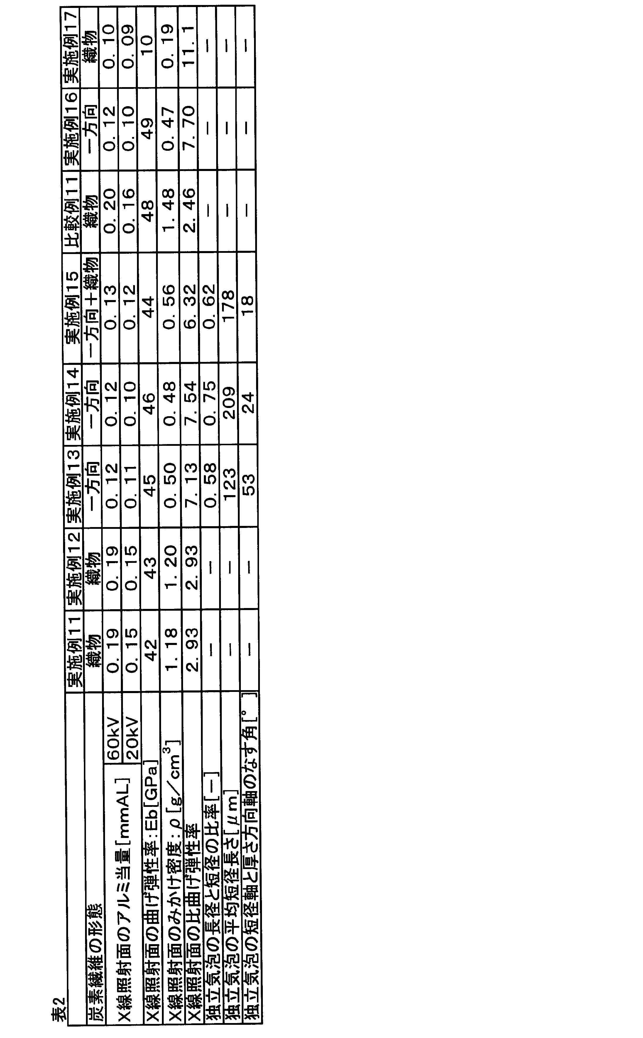
本出願は、2018年3月23日出願の日本特許出願(特願2018-55836)、及び2018年3月23日出願の日本特許出願(特願2018-55840)に基づくものであり、その内容はここに参照として取り込まれる。
2 マンモグラフィ装置本体
3 圧迫板
4 X線発生部
5 X線照射面
6 マンモグラフィ装置用撮影台の底面
7 立ち壁部
8 開口部
9 片面型
10 A面
11 B面
12 C面
13 一方向炭素繊維プリプレグ
14 連結部材
15 プリプレグ積層体
16 可撓性のフィルム
17 ブリーダー
18 シール材
19 バルブ
20 雌型
21 雄型
22 第1の部材
23 第2の部材
24 炭素繊維織物プリプレグ
25 樹脂シート
26 天面の段差部
Claims (17)
- X線画像撮影装置に片持ち梁の状態で支持される撮影台であって、
前記撮影台は、装置と接続する面に開口部を有した面状体と、装置と接続する連結部を含み、
前記面状体における少なくともX線照射面は、一方向に引揃えられた炭素繊維とマトリックス樹脂とを含む一方向炭素繊維複合材料を含み、
前記一方向炭素繊維複合材料で形成された領域に、前記連結部が接合されている、撮影台。 - マンモグラフィ装置本体に片持ち梁の状態で支持されるマンモグラフィ装置用撮影台であって、
前記撮影台は、少なくともX線照射面が炭素繊維複合材料で形成されており、
前記炭素繊維複合材料には、一方向に引揃えられた炭素繊維とマトリックス樹脂とを含む一方向炭素繊維複合材料が含まれる、マンモグラフィ装置用撮影台。 - マンモグラフィ装置本体に片持ち梁の状態で支持される、面状体により形成されたマンモグラフィ装置用撮影台であって、
前記面状体における少なくともX線照射面は、連続繊維とマトリックス樹脂とを含む炭素繊維複合材料を有する表皮材と、前記表皮材より内層側に配された樹脂シートとにより形成された、マンモグラフィ装置用撮影台。 - 前記X線照射面は、更に樹脂シートを含む請求項2に記載のマンモグラフィ装置用撮影台。
- 前記面状体における少なくとも前記X線照射面は、前記炭素繊維複合材料を有する前記表皮材が、前記樹脂シートを含むコア材の両面に配されたサンドイッチ構造により形成される、請求項3または4に記載のマンモグラフィ装置用撮影台。
- 前記樹脂シートがフォーム材である、請求項3から5のいずれか一項に記載のマンモグラフィ装置用撮影台。
- 前記樹脂シートは、略モノフィラメント状、且つ、ランダムに分散した不連続強化繊維を含む、請求項3から6のいずれか一項に記載のマンモグラフィ装置用撮影台。
- 前記樹脂シートは、樹脂と不連続強化繊維と空隙からなる、請求項3から7のいずれか一項に記載のマンモグラフィ装置用撮影台。
- 前記炭素繊維複合材料の最外層には、炭素繊維の織物と樹脂とを含む炭素繊維織物複合材料が含まれる、請求項2から8のいずれか一項に記載のマンモグラフィ装置用撮影台。
- 前記炭素繊維複合材料で形成された領域に、前記マンモグラフィ装置本体と接続する連結部材を有する、請求項2から9のいずれか一項に記載のマンモグラフィ装置用撮影台。
- 前記マンモグラフィ装置本体と接続する接続面を有し、前記接続面に開口部を有する、請求項2から10のいずれか一項に記載のマンモグラフィ装置用撮影台。
- 前記炭素繊維複合材料の比曲げ弾性率が2.50以上である、請求項2から11のいずれか一項に記載のマンモグラフィ装置用撮影台。
(比曲げ弾性率)=(曲げ弾性率)1/3×(密度)-1 - 前記撮影台は、前記X線照射面を含む天面を形成する第1の部材と、前記X線照射面と対面する底面及びその外周に立設された立ち壁部を形成する第2の部材を有する、請求項2から12のいずれか一項に記載のマンモグラフィ装置用撮影台。
- 前記第2の部材が、金属、プラスチック及びエラストマーの群から選ばれる少なくとも1種である、請求項13に記載のマンモグラフィ装置用撮影台。
- 請求項2から14のいずれか一項に記載のマンモグラフィ装置用撮影台と前記マンモグラフィ装置本体とが接続されてなる、マンモグラフィ装置。
- 請求項2から15のいずれか一項に記載のマンモグラフィ装置用撮影台の製造方法であって、
以下に示す工程(I)~(II)を有する、マンモグラフィ装置用撮影台の製造方法。
工程(I):連続繊維からなる炭素繊維(A)と熱硬化性樹脂(B)を含む基材を片面型に賦形する工程
工程(II):前記片面型と前記基材とを含む空間を可撓性のフィルムで覆い、加熱・加圧する工程 - 前記工程(I)において、前記基材を自動積層装置により片面型に賦形する、請求項16に記載のマンモグラフィ装置用撮影台の製造方法。
Priority Applications (6)
| Application Number | Priority Date | Filing Date | Title |
|---|---|---|---|
| CA3094728A CA3094728A1 (en) | 2018-03-23 | 2019-03-20 | Imaging table, mammography apparatus imaging table and manufacturing method therefor, and mammography apparatus |
| CN201980020746.XA CN111936052A (zh) | 2018-03-23 | 2019-03-20 | 拍摄台、钼靶检查装置用拍摄台及其制造方法及钼靶检查装置 |
| JP2019520764A JP7439513B2 (ja) | 2018-03-23 | 2019-03-20 | マンモグラフィ装置用撮影台およびその製造方法およびマンモグラフィ装置 |
| EP19770384.6A EP3769685A4 (en) | 2018-03-23 | 2019-03-20 | IMAGING TABLE, IMAGING TABLE OF MAMMOGRAPHY DEVICE AND ITS MANUFACTURING PROCESS, AND MAMMOGRAPHY DEVICE |
| KR1020207027274A KR20200134241A (ko) | 2018-03-23 | 2019-03-20 | 촬영대, 맘모그라피 장치용 촬영대 및 그 제조 방법 및 맘모그라피 장치 |
| US16/982,677 US11389121B2 (en) | 2018-03-23 | 2019-03-20 | Imaging table, mammography apparatus imaging table and manufacturing method therefor, and mammography apparatus |
Applications Claiming Priority (4)
| Application Number | Priority Date | Filing Date | Title |
|---|---|---|---|
| JP2018-055836 | 2018-03-23 | ||
| JP2018-055840 | 2018-03-23 | ||
| JP2018055836 | 2018-03-23 | ||
| JP2018055840 | 2018-03-23 |
Publications (1)
| Publication Number | Publication Date |
|---|---|
| WO2019182076A1 true WO2019182076A1 (ja) | 2019-09-26 |
Family
ID=67987855
Family Applications (1)
| Application Number | Title | Priority Date | Filing Date |
|---|---|---|---|
| PCT/JP2019/011937 Ceased WO2019182076A1 (ja) | 2018-03-23 | 2019-03-20 | 撮影台、マンモグラフィ装置用撮影台およびその製造方法およびマンモグラフィ装置 |
Country Status (8)
| Country | Link |
|---|---|
| US (1) | US11389121B2 (ja) |
| EP (1) | EP3769685A4 (ja) |
| JP (1) | JP7439513B2 (ja) |
| KR (1) | KR20200134241A (ja) |
| CN (1) | CN111936052A (ja) |
| CA (1) | CA3094728A1 (ja) |
| TW (1) | TW202002900A (ja) |
| WO (1) | WO2019182076A1 (ja) |
Cited By (2)
| Publication number | Priority date | Publication date | Assignee | Title |
|---|---|---|---|---|
| JP2022122806A (ja) * | 2021-02-10 | 2022-08-23 | 東芝Itコントロールシステム株式会社 | 放射線検査装置 |
| WO2023032893A1 (ja) * | 2021-09-01 | 2023-03-09 | 東レ株式会社 | X線透過部材 |
Families Citing this family (1)
| Publication number | Priority date | Publication date | Assignee | Title |
|---|---|---|---|---|
| CN112519374B (zh) * | 2020-11-26 | 2023-03-03 | 欧瑞特佳(三河)科技有限公司 | 一种透x光医用板材的制备方法、板材和应用 |
Citations (11)
| Publication number | Priority date | Publication date | Assignee | Title |
|---|---|---|---|---|
| WO2000056539A1 (en) * | 1999-03-23 | 2000-09-28 | Toray Industries, Inc. | Composite reinforcing fiber base material, preform and production method for fiber reinforced plastic |
| JP2003207864A (ja) * | 2002-01-10 | 2003-07-25 | Konica Corp | 放射線画像撮影用カセッテ及び乳房撮影用カセッテ |
| JP2005313613A (ja) * | 2004-03-29 | 2005-11-10 | Toray Ind Inc | 繊維強化樹脂製サンドイッチパネル |
| JP2009230000A (ja) * | 2008-03-25 | 2009-10-08 | Toray Ind Inc | 放射線画像撮影用カセッテおよびその製造方法 |
| JP2010035622A (ja) | 2008-07-31 | 2010-02-18 | Toshiba Corp | マンモグラフィ装置 |
| JP2010039267A (ja) | 2008-08-06 | 2010-02-18 | Konica Minolta Medical & Graphic Inc | 医療用カセッテ及び画像形成方法 |
| US20150164449A1 (en) * | 2013-12-17 | 2015-06-18 | Samsung Electronics Co., Ltd. | Mammography apparatus |
| JP2016022061A (ja) * | 2014-07-17 | 2016-02-08 | シャープ株式会社 | 乳房画像撮影装置 |
| JP2017122382A (ja) * | 2015-12-25 | 2017-07-13 | 東レ株式会社 | 止水板 |
| JP2018055840A (ja) | 2016-09-26 | 2018-04-05 | 東芝ライテック株式会社 | 照明システム |
| JP2018055836A (ja) | 2016-09-26 | 2018-04-05 | 日産自動車株式会社 | 非水電解質二次電池用正極 |
Family Cites Families (11)
| Publication number | Priority date | Publication date | Assignee | Title |
|---|---|---|---|---|
| JPS60236634A (ja) * | 1984-05-10 | 1985-11-25 | 三菱レイヨン株式会社 | 放射線診断装置用天板 |
| US5960057A (en) * | 1997-10-17 | 1999-09-28 | Southeastern Universities Research Assn. | Radiology utilizing a gas multiwire detector with resolution enhancement |
| JP5126405B2 (ja) * | 2004-03-29 | 2013-01-23 | 東レ株式会社 | 繊維強化樹脂製サンドイッチパネルの製造方法 |
| DE102004034239A1 (de) * | 2004-07-15 | 2006-02-02 | Siemens Ag | Gerät zur medizinischen Bildgebung |
| US8331536B2 (en) * | 2009-09-18 | 2012-12-11 | General Electric Company | Apparatus for reducing scattered X-ray detection and method of same |
| DE102010019019A1 (de) * | 2010-05-03 | 2011-11-03 | Siemens Aktiengesellschaft | Verbesserte Brustlagerung bei Mammografieaufnahmen, insbesondere MLO-Aufnahmen |
| JP6222809B2 (ja) * | 2013-05-30 | 2017-11-01 | 東芝メディカルシステムズ株式会社 | マンモグラフィ装置 |
| CN106794637B (zh) * | 2014-10-17 | 2019-05-17 | 东丽株式会社 | 纤维增强复合材料的制造方法、树脂基材及预成型体 |
| US11001011B2 (en) * | 2016-02-23 | 2021-05-11 | Toray Industries, Inc. | Method of producing fiber reinforced composite material |
| CN109691248B (zh) * | 2016-09-26 | 2021-07-30 | 东丽株式会社 | 电子设备壳体及其制造方法 |
| US11800656B2 (en) * | 2016-09-26 | 2023-10-24 | Toray Industries, Inc. | Electronic device housing |
-
2019
- 2019-03-20 EP EP19770384.6A patent/EP3769685A4/en not_active Withdrawn
- 2019-03-20 US US16/982,677 patent/US11389121B2/en active Active
- 2019-03-20 WO PCT/JP2019/011937 patent/WO2019182076A1/ja not_active Ceased
- 2019-03-20 JP JP2019520764A patent/JP7439513B2/ja active Active
- 2019-03-20 CN CN201980020746.XA patent/CN111936052A/zh active Pending
- 2019-03-20 CA CA3094728A patent/CA3094728A1/en not_active Abandoned
- 2019-03-20 KR KR1020207027274A patent/KR20200134241A/ko not_active Withdrawn
- 2019-03-22 TW TW108110128A patent/TW202002900A/zh unknown
Patent Citations (11)
| Publication number | Priority date | Publication date | Assignee | Title |
|---|---|---|---|---|
| WO2000056539A1 (en) * | 1999-03-23 | 2000-09-28 | Toray Industries, Inc. | Composite reinforcing fiber base material, preform and production method for fiber reinforced plastic |
| JP2003207864A (ja) * | 2002-01-10 | 2003-07-25 | Konica Corp | 放射線画像撮影用カセッテ及び乳房撮影用カセッテ |
| JP2005313613A (ja) * | 2004-03-29 | 2005-11-10 | Toray Ind Inc | 繊維強化樹脂製サンドイッチパネル |
| JP2009230000A (ja) * | 2008-03-25 | 2009-10-08 | Toray Ind Inc | 放射線画像撮影用カセッテおよびその製造方法 |
| JP2010035622A (ja) | 2008-07-31 | 2010-02-18 | Toshiba Corp | マンモグラフィ装置 |
| JP2010039267A (ja) | 2008-08-06 | 2010-02-18 | Konica Minolta Medical & Graphic Inc | 医療用カセッテ及び画像形成方法 |
| US20150164449A1 (en) * | 2013-12-17 | 2015-06-18 | Samsung Electronics Co., Ltd. | Mammography apparatus |
| JP2016022061A (ja) * | 2014-07-17 | 2016-02-08 | シャープ株式会社 | 乳房画像撮影装置 |
| JP2017122382A (ja) * | 2015-12-25 | 2017-07-13 | 東レ株式会社 | 止水板 |
| JP2018055840A (ja) | 2016-09-26 | 2018-04-05 | 東芝ライテック株式会社 | 照明システム |
| JP2018055836A (ja) | 2016-09-26 | 2018-04-05 | 日産自動車株式会社 | 非水電解質二次電池用正極 |
Non-Patent Citations (1)
| Title |
|---|
| See also references of EP3769685A4 |
Cited By (4)
| Publication number | Priority date | Publication date | Assignee | Title |
|---|---|---|---|---|
| JP2022122806A (ja) * | 2021-02-10 | 2022-08-23 | 東芝Itコントロールシステム株式会社 | 放射線検査装置 |
| WO2023032893A1 (ja) * | 2021-09-01 | 2023-03-09 | 東レ株式会社 | X線透過部材 |
| JP7243940B1 (ja) * | 2021-09-01 | 2023-03-22 | 東レ株式会社 | X線透過部材 |
| US12591074B2 (en) | 2021-09-01 | 2026-03-31 | Toray Industries, Inc. | X-ray transmission member |
Also Published As
| Publication number | Publication date |
|---|---|
| CN111936052A (zh) | 2020-11-13 |
| US20210106293A1 (en) | 2021-04-15 |
| CA3094728A1 (en) | 2019-09-26 |
| JP7439513B2 (ja) | 2024-02-28 |
| EP3769685A1 (en) | 2021-01-27 |
| JPWO2019182076A1 (ja) | 2021-02-04 |
| TW202002900A (zh) | 2020-01-16 |
| KR20200134241A (ko) | 2020-12-01 |
| US11389121B2 (en) | 2022-07-19 |
| EP3769685A4 (en) | 2021-12-15 |
Similar Documents
| Publication | Publication Date | Title |
|---|---|---|
| JP6325193B2 (ja) | 炭素繊維強化複合材及びその製造方法 | |
| JP5126405B2 (ja) | 繊維強化樹脂製サンドイッチパネルの製造方法 | |
| JP2008207523A (ja) | X線カセッテ用パネル | |
| JP7439513B2 (ja) | マンモグラフィ装置用撮影台およびその製造方法およびマンモグラフィ装置 | |
| JP6357834B2 (ja) | 繊維強化プラスチック積層体及びその製造方法 | |
| JP7404486B2 (ja) | 炭素繊維強化成形体 | |
| JP6747590B2 (ja) | 撮影台およびその製造方法、マンモグラフィ装置用撮影台およびその製造方法およびマンモグラフィ装置 | |
| US20250083427A1 (en) | X-ray-transmitting member, x-ray inspection device, and article to be subjected to x-ray inspection | |
| JP2006035671A (ja) | Frp構造体 | |
| JP4178964B2 (ja) | 医療機器用天板 | |
| JP7439616B2 (ja) | サンドイッチ構造体およびその製造方法 | |
| JP2018051000A (ja) | 放射線機器用天板およびx線ct装置 | |
| JP2007020986A (ja) | 医療用放射線機器天板およびx線ct装置 | |
| JP7243940B1 (ja) | X線透過部材 | |
| JP2012192122A (ja) | 医療機器用天板 | |
| KR101125019B1 (ko) | X-레이 검사용 베드 및 그 제조방법 | |
| JP2004070253A (ja) | X線カセッテ用フロントパネル及びx線カセッテ |
Legal Events
| Date | Code | Title | Description |
|---|---|---|---|
| ENP | Entry into the national phase |
Ref document number: 2019520764 Country of ref document: JP Kind code of ref document: A |
|
| 121 | Ep: the epo has been informed by wipo that ep was designated in this application |
Ref document number: 19770384 Country of ref document: EP Kind code of ref document: A1 |
|
| ENP | Entry into the national phase |
Ref document number: 3094728 Country of ref document: CA |
|
| ENP | Entry into the national phase |
Ref document number: 20207027274 Country of ref document: KR Kind code of ref document: A |
|
| NENP | Non-entry into the national phase |
Ref country code: DE |
|
| WWE | Wipo information: entry into national phase |
Ref document number: 2019770384 Country of ref document: EP |