WO2019182076A1 - Table d'imagerie, table d'imagerie d'appareil de mammographie et son procédé de fabrication, et appareil de mammographie - Google Patents
Table d'imagerie, table d'imagerie d'appareil de mammographie et son procédé de fabrication, et appareil de mammographie Download PDFInfo
- Publication number
- WO2019182076A1 WO2019182076A1 PCT/JP2019/011937 JP2019011937W WO2019182076A1 WO 2019182076 A1 WO2019182076 A1 WO 2019182076A1 JP 2019011937 W JP2019011937 W JP 2019011937W WO 2019182076 A1 WO2019182076 A1 WO 2019182076A1
- Authority
- WO
- WIPO (PCT)
- Prior art keywords
- mammography apparatus
- carbon fiber
- resin
- stand
- mammography
- Prior art date
- Legal status (The legal status is an assumption and is not a legal conclusion. Google has not performed a legal analysis and makes no representation as to the accuracy of the status listed.)
- Ceased
Links
Images
















Classifications
-
- A—HUMAN NECESSITIES
- A61—MEDICAL OR VETERINARY SCIENCE; HYGIENE
- A61B—DIAGNOSIS; SURGERY; IDENTIFICATION
- A61B6/00—Apparatus or devices for radiation diagnosis; Apparatus or devices for radiation diagnosis combined with radiation therapy equipment
- A61B6/04—Positioning of patients; Tiltable beds or the like
- A61B6/0407—Supports, e.g. tables or beds, for the body or parts of the body
- A61B6/0435—Supports, e.g. tables or beds, for the body or parts of the body with means for imaging suspended breasts
-
- A—HUMAN NECESSITIES
- A61—MEDICAL OR VETERINARY SCIENCE; HYGIENE
- A61B—DIAGNOSIS; SURGERY; IDENTIFICATION
- A61B6/00—Apparatus or devices for radiation diagnosis; Apparatus or devices for radiation diagnosis combined with radiation therapy equipment
- A61B6/04—Positioning of patients; Tiltable beds or the like
- A61B6/0407—Supports, e.g. tables or beds, for the body or parts of the body
- A61B6/0414—Supports, e.g. tables or beds, for the body or parts of the body with compression means
-
- A—HUMAN NECESSITIES
- A61—MEDICAL OR VETERINARY SCIENCE; HYGIENE
- A61B—DIAGNOSIS; SURGERY; IDENTIFICATION
- A61B6/00—Apparatus or devices for radiation diagnosis; Apparatus or devices for radiation diagnosis combined with radiation therapy equipment
- A61B6/04—Positioning of patients; Tiltable beds or the like
- A61B6/0407—Supports, e.g. tables or beds, for the body or parts of the body
- A61B6/0442—Supports, e.g. tables or beds, for the body or parts of the body made of non-metallic materials
-
- A—HUMAN NECESSITIES
- A61—MEDICAL OR VETERINARY SCIENCE; HYGIENE
- A61B—DIAGNOSIS; SURGERY; IDENTIFICATION
- A61B6/00—Apparatus or devices for radiation diagnosis; Apparatus or devices for radiation diagnosis combined with radiation therapy equipment
- A61B6/50—Apparatus or devices for radiation diagnosis; Apparatus or devices for radiation diagnosis combined with radiation therapy equipment specially adapted for specific body parts; specially adapted for specific clinical applications
- A61B6/502—Apparatus or devices for radiation diagnosis; Apparatus or devices for radiation diagnosis combined with radiation therapy equipment specially adapted for specific body parts; specially adapted for specific clinical applications for diagnosis of breast, i.e. mammography
-
- B—PERFORMING OPERATIONS; TRANSPORTING
- B29—WORKING OF PLASTICS; WORKING OF SUBSTANCES IN A PLASTIC STATE IN GENERAL
- B29C—SHAPING OR JOINING OF PLASTICS; SHAPING OF MATERIAL IN A PLASTIC STATE, NOT OTHERWISE PROVIDED FOR; AFTER-TREATMENT OF THE SHAPED PRODUCTS, e.g. REPAIRING
- B29C43/00—Compression moulding, i.e. applying external pressure to flow the moulding material; Apparatus therefor
- B29C43/02—Compression moulding, i.e. applying external pressure to flow the moulding material; Apparatus therefor of articles of definite length, i.e. discrete articles
- B29C43/10—Isostatic pressing, i.e. using non-rigid pressure-exerting members against rigid parts or dies
-
- B—PERFORMING OPERATIONS; TRANSPORTING
- B29—WORKING OF PLASTICS; WORKING OF SUBSTANCES IN A PLASTIC STATE IN GENERAL
- B29C—SHAPING OR JOINING OF PLASTICS; SHAPING OF MATERIAL IN A PLASTIC STATE, NOT OTHERWISE PROVIDED FOR; AFTER-TREATMENT OF THE SHAPED PRODUCTS, e.g. REPAIRING
- B29C70/00—Shaping composites, i.e. plastics material comprising reinforcements, fillers or preformed parts, e.g. inserts
-
- B—PERFORMING OPERATIONS; TRANSPORTING
- B29—WORKING OF PLASTICS; WORKING OF SUBSTANCES IN A PLASTIC STATE IN GENERAL
- B29C—SHAPING OR JOINING OF PLASTICS; SHAPING OF MATERIAL IN A PLASTIC STATE, NOT OTHERWISE PROVIDED FOR; AFTER-TREATMENT OF THE SHAPED PRODUCTS, e.g. REPAIRING
- B29C70/00—Shaping composites, i.e. plastics material comprising reinforcements, fillers or preformed parts, e.g. inserts
- B29C70/04—Shaping composites, i.e. plastics material comprising reinforcements, fillers or preformed parts, e.g. inserts comprising reinforcements only, e.g. self-reinforcing plastics
- B29C70/06—Fibrous reinforcements only
-
- B—PERFORMING OPERATIONS; TRANSPORTING
- B32—LAYERED PRODUCTS
- B32B—LAYERED PRODUCTS, i.e. PRODUCTS BUILT-UP OF STRATA OF FLAT OR NON-FLAT, e.g. CELLULAR OR HONEYCOMB, FORM
- B32B2260/00—Layered product comprising an impregnated, embedded, or bonded layer wherein the layer comprises an impregnation, embedding, or binder material
- B32B2260/02—Composition of the impregnated, bonded or embedded layer
- B32B2260/021—Fibrous or filamentary layer
- B32B2260/023—Two or more layers
-
- B—PERFORMING OPERATIONS; TRANSPORTING
- B32—LAYERED PRODUCTS
- B32B—LAYERED PRODUCTS, i.e. PRODUCTS BUILT-UP OF STRATA OF FLAT OR NON-FLAT, e.g. CELLULAR OR HONEYCOMB, FORM
- B32B2262/00—Composition or structural features of fibres which form a fibrous or filamentary layer or are present as additives
- B32B2262/10—Inorganic fibres
- B32B2262/106—Carbon fibres, e.g. graphite fibres
-
- B—PERFORMING OPERATIONS; TRANSPORTING
- B32—LAYERED PRODUCTS
- B32B—LAYERED PRODUCTS, i.e. PRODUCTS BUILT-UP OF STRATA OF FLAT OR NON-FLAT, e.g. CELLULAR OR HONEYCOMB, FORM
- B32B2535/00—Medical equipment, e.g. bandage, prostheses or catheter
-
- B—PERFORMING OPERATIONS; TRANSPORTING
- B32—LAYERED PRODUCTS
- B32B—LAYERED PRODUCTS, i.e. PRODUCTS BUILT-UP OF STRATA OF FLAT OR NON-FLAT, e.g. CELLULAR OR HONEYCOMB, FORM
- B32B27/00—Layered products comprising a layer of synthetic resin
- B32B27/04—Layered products comprising a layer of synthetic resin as impregnant, bonding, or embedding substance
-
- B—PERFORMING OPERATIONS; TRANSPORTING
- B32—LAYERED PRODUCTS
- B32B—LAYERED PRODUCTS, i.e. PRODUCTS BUILT-UP OF STRATA OF FLAT OR NON-FLAT, e.g. CELLULAR OR HONEYCOMB, FORM
- B32B5/00—Layered products characterised by the non- homogeneity or physical structure, i.e. comprising a fibrous, filamentary, particulate or foam layer; Layered products characterised by having a layer differing constitutionally or physically in different parts
- B32B5/02—Layered products characterised by the non- homogeneity or physical structure, i.e. comprising a fibrous, filamentary, particulate or foam layer; Layered products characterised by having a layer differing constitutionally or physically in different parts characterised by structural features of a fibrous or filamentary layer
- B32B5/024—Woven fabric
-
- B—PERFORMING OPERATIONS; TRANSPORTING
- B32—LAYERED PRODUCTS
- B32B—LAYERED PRODUCTS, i.e. PRODUCTS BUILT-UP OF STRATA OF FLAT OR NON-FLAT, e.g. CELLULAR OR HONEYCOMB, FORM
- B32B5/00—Layered products characterised by the non- homogeneity or physical structure, i.e. comprising a fibrous, filamentary, particulate or foam layer; Layered products characterised by having a layer differing constitutionally or physically in different parts
- B32B5/02—Layered products characterised by the non- homogeneity or physical structure, i.e. comprising a fibrous, filamentary, particulate or foam layer; Layered products characterised by having a layer differing constitutionally or physically in different parts characterised by structural features of a fibrous or filamentary layer
- B32B5/12—Layered products characterised by the non- homogeneity or physical structure, i.e. comprising a fibrous, filamentary, particulate or foam layer; Layered products characterised by having a layer differing constitutionally or physically in different parts characterised by structural features of a fibrous or filamentary layer characterised by the relative arrangement of fibres or filaments of different layers, e.g. the fibres or filaments being parallel or perpendicular to each other
-
- B—PERFORMING OPERATIONS; TRANSPORTING
- B32—LAYERED PRODUCTS
- B32B—LAYERED PRODUCTS, i.e. PRODUCTS BUILT-UP OF STRATA OF FLAT OR NON-FLAT, e.g. CELLULAR OR HONEYCOMB, FORM
- B32B5/00—Layered products characterised by the non- homogeneity or physical structure, i.e. comprising a fibrous, filamentary, particulate or foam layer; Layered products characterised by having a layer differing constitutionally or physically in different parts
- B32B5/22—Layered products characterised by the non- homogeneity or physical structure, i.e. comprising a fibrous, filamentary, particulate or foam layer; Layered products characterised by having a layer differing constitutionally or physically in different parts characterised by the presence of two or more layers which are next to each other and are fibrous, filamentary, formed of particles or foamed
- B32B5/24—Layered products characterised by the non- homogeneity or physical structure, i.e. comprising a fibrous, filamentary, particulate or foam layer; Layered products characterised by having a layer differing constitutionally or physically in different parts characterised by the presence of two or more layers which are next to each other and are fibrous, filamentary, formed of particles or foamed one layer being a fibrous or filamentary layer
- B32B5/245—Layered products characterised by the non- homogeneity or physical structure, i.e. comprising a fibrous, filamentary, particulate or foam layer; Layered products characterised by having a layer differing constitutionally or physically in different parts characterised by the presence of two or more layers which are next to each other and are fibrous, filamentary, formed of particles or foamed one layer being a fibrous or filamentary layer another layer next to it being a foam layer
Definitions
- the present invention relates to an imaging table that is supported in a cantilever state by an X-ray imaging apparatus, and further to an imaging table for a mammography apparatus that is supported in a cantilever state by a main body of the mammography apparatus.
- Patent Document 1 There is known a mammography apparatus that uses a subject's breast for examination and obtains image data by X-ray imaging of the breast (Patent Document 1).
- This mammography apparatus is provided with an imaging table and a compression plate for compressing a breast in order to obtain image data with high contrast and high resolution with little blur due to geometric blur and body movement. Then, the breast supported on the imaging table is compressed with a compression plate, the X-ray is irradiated to the breast maintained at a uniform thickness, and the X-ray transmitted through the breast is detected to generate image data.
- the imaging table Since the imaging table has an X-ray detection unit for detecting X-rays transmitted through the compression plate and the breast as a subject, it is formed of a material having excellent X-ray permeability. In addition, since the subject is compressed to a uniform thickness by the compression plate at the time of shooting, an external force is also applied to the shooting table, and the image data obtained when the shooting table is easily deformed by the external force. The contrast and resolution of the image are reduced. Therefore, in general, the photographing stand is formed of a material having excellent rigidity. From the above background, as described in Patent Document 1, a carbon fiber reinforced composite material (carbon composite material) having excellent X-ray permeability and high rigidity has been suitably used for the mammography apparatus imaging stand.
- Patent Document 2 a method of directly photographing an object placed on a cassette is disclosed (Patent Document 2). Since this imaging method uses a thin rectangular cassette, it is possible to suppress an increase in weight and to have an excellent handling property. In addition, since the front member irradiated with X-rays is integrated with the outer peripheral frame member, there is an effect that deformation during imaging can be suppressed.
- a front member is a laminate in which a plurality of layers (carbon fiber layers) in which a large number of carbon fiber filaments are arranged and arranged in one direction are stacked and impregnated with a thermosetting resin. It is described that it is composed.
- the mammography apparatus described in Patent Document 1 discloses that the imaging stand is formed of carbon fiber, it also suggests disclosure of the requirements, for example, the form of the fiber and the configuration of the region formed of carbon fiber. It has not been done.
- the imaging table for mammography devices found in general market products has a hollow box shape, but even if it uses a carbon fiber composite material, it has a woven form because of its excellent shape following ability. There are actual conditions limited to materials. Such a carbon woven composite material forms a woven structure in the matrix resin while the carbon fibers have undulations. Excellent.
- the carbon woven composite material cannot fully exhibit the elastic modulus and strength potential of the carbon fiber due to the undulation of the carbon fiber.
- limiting is added to fiber arrangement
- the carbon fiber composite material has carbon fibers, it is excellent in rigidity and strength. In order to achieve this, the carbon fibers and the matrix resin need to be molded without including voids, and the X-ray permeability is improved. There is a limit in reducing the weight in the X-ray transmission direction that affects the X-ray transmission and improving the X-ray transmission.
- a medical cassette capable of mammography photography is described, and a plurality of layers in which a large number of carbon fiber filaments are arranged and arranged in one direction are used as a front member.
- the cassette has excellent rigidity.
- the front panel has a flat plate shape, a lightweight core material can be included, so that it is possible to take an aspect in which X-ray transmission can be improved.
- the medical cassette is a container in which a film used for X-ray imaging is loaded, and the required characteristics are different from those of the mammography apparatus imaging table supported in a cantilever state by the mammography apparatus.
- the standing wall portion Since it is composed of a flat plate-shaped front member and a back member and a frame that forms a standing wall, the standing wall portion is easily deformed and forms an X-ray irradiation surface under conditions where a center surface load acts as in mammography. Failure can occur at the boundary between the front panel and the frame forming the standing wall.
- the cassette is generally a thin rectangular parallelepiped, there is a limit to the proportion of the core material that can be included. Since it is easily deformed by the load received from the plate, the contrast and resolution of the obtained image data may be reduced. Furthermore, there is a concern that the standing wall bites into the subject and gives discomfort during mammography photography. Further, if a large number of fibers are arranged in one direction, there is a concern that the fibers cannot sufficiently follow the shape when forming a member having a complicated shape.
- the medical cassette can be separated from the front member and the back member as described in Patent Document 2, and can be formed separately. However, in the case of a mammography apparatus photographing stand, it is divided into a plurality of members. However, it is generally considered that molding using unidirectionally arranged fibers is not easy.
- the present invention has been made in view of the above problems, and an object thereof is to provide a thin-walled, high-rigidity photographing stand and a photographing stand for a mammography apparatus.
- a further object is to provide a mammography apparatus imaging stand that achieves high X-ray transparency and high rigidity.
- the photographing stand of the present invention has the following configuration.
- An imaging table supported in a cantilevered state by an X-ray imaging apparatus includes a planar body having an opening on a surface connected to the device, and a connecting portion connected to the device, At least the X-ray irradiation surface in the planar body includes a unidirectional carbon fiber composite material including carbon fibers and a matrix resin aligned in one direction, An imaging stand in which the connecting portion is joined to a region formed of the unidirectional carbon fiber composite material.
- the mammography apparatus photographing stand of the present invention has the following configuration.
- the imaging table has at least an X-ray irradiation surface formed of the carbon fiber composite material,
- the imaging table for a mammography apparatus of the present invention has the following configuration.
- a mammography apparatus imaging stand formed by a planar body supported in a cantilever state on the mammography apparatus body,
- the exposure dose of the subject is reduced by the effect of improving the X-ray permeability by the thin wall, and the deflection due to the load load at the time of photographing is suppressed by the effect of increasing the rigidity.
- a photographing stand capable of improving the image quality can be provided.
- the exposure dose of the subject is reduced by the effect of improving the X-ray permeability by the thin wall, and the deflection due to the load load at the time of imaging is suppressed by the effect of increasing the rigidity.
- FIG. 1 is a block diagram showing a configuration of a mammography apparatus according to an embodiment of the present invention.
- FIG. 2 is a schematic diagram showing an example of the appearance of the mammography apparatus photographing stand according to the embodiment of the present invention.
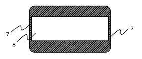
- FIG. 3A is a schematic diagram illustrating an example of an opening of the mammography apparatus photographing stand according to the embodiment of the present invention.
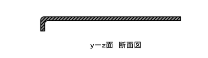
- FIG. 3B is a cross-sectional view showing an example of a cross-sectional shape in the yz plane of FIG.
- FIG. 3C is a schematic diagram illustrating an example of an opening of the imaging table for the mammography apparatus according to the embodiment of the present invention.
- FIG. 1 is a block diagram showing a configuration of a mammography apparatus according to an embodiment of the present invention.
- FIG. 2 is a schematic diagram showing an example of the appearance of the mammography apparatus photographing stand according to the embodiment of the present invention.
- FIG. 3A is a schematic diagram illustrating an example of an opening of the ma
- FIG. 3d is a cross-sectional view showing an example of a cross-sectional shape in the yz plane of FIG.
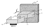
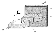
- FIG. 4 is a schematic view showing an example of a single-sided mold for molding a mammography apparatus photographing stand according to an embodiment of the present invention.
- FIG. 5 is a schematic diagram showing an example of a part of the step (I) of the method for manufacturing the photographing stand for the mammography apparatus according to the embodiment of the present invention.
- FIG. 6 is a schematic diagram illustrating an example of a part of the step (I) of the method for manufacturing the imaging table for the mammography apparatus according to the embodiment of the present invention.
- FIG. 7 is a schematic diagram showing an example of a part of the step (I) of the method for manufacturing the photographing stand for the mammography apparatus according to the embodiment of the present invention.
- FIG. 8 a is a schematic diagram illustrating an example of the appearance of the mammography apparatus photographing stand according to the embodiment of the present invention.
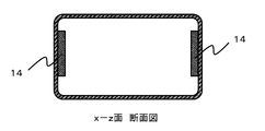
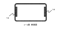
- FIG. 8b is a cross-sectional view showing an example of a cross-sectional shape in the xz plane of FIG. 8a.
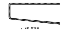
- 8c is a cross-sectional view showing an example of a cross-sectional shape in the yz plane of FIG. 8a.
- FIG. 9 is a schematic diagram illustrating an example of a process (II) of the method for manufacturing the imaging table for the mammography apparatus according to the embodiment of the present invention.
- FIG. 10 is a schematic diagram showing an example of a double-sided mold for molding a mammography apparatus photographing stand according to an embodiment of the present invention.
- FIG. 11 a is a schematic diagram illustrating an example of an appearance of a first member constituting the mammography apparatus photographing stand according to the embodiment of the present invention.
- 11b is a cross-sectional view showing an example of a cross-sectional shape in the yz plane of FIG. 11a.
- FIG. 12 a is a schematic diagram illustrating an example of an appearance of a second member constituting the mammography apparatus photographing stand according to the embodiment of the present invention.
- 12b is a cross-sectional view showing an example of a cross-sectional shape in the yz plane of FIG. 12a.
- FIG. 11 a is a schematic diagram illustrating an example of an appearance of a first member constituting the mammography apparatus photographing stand according to the embodiment of the present invention.
- 11b is a cross-sectional view showing an example of
- FIG. 13A is a schematic diagram illustrating an example of the appearance of a mammography apparatus photographing stand including the first member according to FIG. 11A and the second member according to FIG. 12A.
- FIG. 13B is a cross-sectional view showing an example of a cross-sectional shape in the xz plane of FIG. 13A.
- 13c is a cross-sectional view showing an example of a cross-sectional shape in the yz plane of FIG. 13a.
- FIG. 14 is a schematic diagram illustrating an example of a process of a method for manufacturing a mammography apparatus photographing stand according to an embodiment of the present invention.
- FIG. 15 is a schematic diagram illustrating an example of steps of a method for manufacturing a mammography apparatus photographing stand according to an embodiment of the present invention.
- FIG. 16 is a schematic diagram illustrating an example of a process of a method for manufacturing a mammography apparatus photographing stand according to an embodiment of the present invention.
- FIG. 17A is a schematic diagram illustrating an example of an appearance and a cross-sectional shape of the mammography apparatus photographing stand according to the embodiment of the present invention.
- FIG. 17B is a cross-sectional view showing an example of a cross-sectional shape in the xz plane of FIG. 17A.
- FIG. 17c is a cross-sectional view showing an example of a cross-sectional shape in the yz plane of FIG. 17a.
- FIG. 17A is a schematic diagram illustrating an example of an appearance and a cross-sectional shape of the mammography apparatus photographing stand according to the embodiment of the present invention.
- FIG. 17B is a cross-sectional view showing an example of a cross-sectional shape in the xz plane of FIG. 17A.
- FIG. 17c is a cross-sectional view showing
- FIG. 18 a is a schematic diagram illustrating an example of an appearance of a first member constituting the mammography apparatus photographing stand according to the embodiment of the present invention.
- 18b is a cross-sectional view showing an example of a cross-sectional shape in the yz plane of FIG. 18a.
- FIG. 19A is a schematic diagram illustrating an example of the appearance of the mammography apparatus photographing stand according to the embodiment of the present invention.
- FIG. 19B is a cross-sectional view showing an example of a cross-sectional shape in the xz plane of FIG. 19A.
- FIG. 19c is a cross-sectional view showing an example of a cross-sectional shape in the yz plane of FIG. 19a.
- 20A is a schematic diagram illustrating an example of the appearance of the mammography apparatus photographing stand according to the embodiment of the present invention.
- 20b is a cross-sectional view showing an example of a cross-sectional shape in the xz plane of FIG. 20a.
- 20c is a cross-sectional view showing an example of a cross-sectional shape in the yz plane of FIG. 20a.
- FIG. 21 is a schematic diagram showing an example of the appearance of the mammography apparatus photographing stand according to the embodiment of the present invention.
- 22a is a cross-sectional view showing an example of a cross-sectional shape in the yz plane of FIG. 19a.
- 22b is a cross-sectional view showing an example of a cross-sectional shape in the yz plane of FIG. 19a.
- An imaging table is an imaging table supported in a cantilevered state by an X-ray imaging apparatus, and is a planar body having an opening on a surface connected to the X-ray imaging apparatus. And at least an X-ray irradiation surface of the planar body includes a unidirectional carbon fiber composite material including carbon fibers and a matrix resin aligned in one direction, and the one direction The connecting portion is joined to a region formed of a carbon fiber composite material.
- the application is not limited as long as the X-ray imaging apparatus is supported in a cantilever state, but an imaging table for a mammography apparatus can be exemplified.
- the mammography apparatus is formed by connecting a mammography apparatus imaging stand to the mammography apparatus main body.
- a mammography apparatus imaging stand to the mammography apparatus main body.
- the imaging table for the mammography apparatus uses a unidirectional carbon fiber composite material on at least the X-ray irradiation surface, so that it has a high rigidity compared to a conventional carbon fiber woven composite material, and therefore affects the amount of deflection.
- the flexural rigidity which is a characteristic that gives the value
- the plate thickness can be made thinner than that of the carbon fiber woven composite material. Therefore, the attenuation of the X-ray intensity until it passes through the mammography apparatus imaging table and reaches the internal X-ray detector is reduced, that is, the X-ray permeability is improved, so that the exposure dose of the subject is reduced. Can do.
- the plate thickness here is the plate thickness of the X-ray irradiated surface that contributes to X-ray transmission, and is preferably 0.5 mm or more and 5.0 mm or less. More preferably, it is 0.8 mm or more and 3.5 mm or less. The range which combined any of said upper limit and lower limit may be sufficient.
- the plate thickness is less than 0.5 mm, the rigidity as a photographing stand cannot be ensured, and there is a possibility that the plate is easily deformed during photographing.
- the plate thickness is thicker than 5.0 mm, the X-ray transmission is inferior, so that it is necessary to increase the X-ray irradiation intensity, which may increase the exposure dose of the subject in one imaging.
- the main body of the mammography apparatus includes an X-ray generation unit and a compression plate. Examples of the arrangement thereof include an embodiment as shown in FIG.
- the mammography apparatus photographing stand 1 according to the embodiment of the present invention is supported by the mammography apparatus main body 2 in a cantilever state.
- the mammography apparatus shown in FIG. 1 includes a mammography apparatus main body 2, a mammography apparatus imaging table 1, a compression plate 3, and an X-ray generation unit 4.
- the mammography apparatus imaging table 1 includes an X-ray irradiation surface 5 and a bottom surface. 6 is provided.
- the imaging table 1 for mammography apparatus is formed by a planar body having a sufficiently long side forming a surface rather than a plate thickness, and is generally a box having a hollow inside.
- the shape of the mold, and an X-ray detector is often provided inside.
- Such an X-ray detector may be directly connected to the mammography apparatus main body, or may be fixed in the imaging table and connected to the mammography apparatus main body 2 by wiring.
- the said X-ray irradiation surface is a plane area
- the planar region may be the entire top surface of the imaging table or a part thereof, but from the viewpoint of X-ray transmission and rigidity, the X-irradiated surface is formed of a carbon fiber composite material. Moreover, the X-ray irradiation surface may further contain a resin sheet. More preferably, a stepped portion is provided in the top surface region other than the X-ray irradiation surface. By providing such a shape, since the step portion functions as a standing wall, it is possible to suppress deflection due to the load of the compression plate during mammography photography. In addition, the area for storing the X-ray detector and the like in the imaging table can be expanded. An example of the position where the step portion is provided is the device connection surface (FIG. 21).
- the imaging stand for the mammography apparatus is lighter on the inner layer side than the skin material having the carbon fiber composite material, as compared with the structure formed by the carbon fiber composite material alone by adopting the above-described configuration. Since the resin sheet is disposed, the attenuation of the X-ray intensity until it passes through the mammography apparatus imaging table and reaches the internal X-ray detector is suppressed, that is, the X-ray permeability is improved. Can be reduced. In addition, since the carbon fiber composite material including continuous fibers forms the skin material, most of the load that is exposed during photographing can be handled by the highly rigid skin material. Therefore, the X-ray transparency can be improved while maintaining rigidity.
- At least the X-ray irradiation surface in the planar body is formed by a sandwich structure in which a skin material having a carbon fiber composite material is disposed on both surfaces of a core material including a resin sheet.
- the structure of the planar body may be a canape structure in which the skin material exists only on one side of the outermost surface, or a sandwich structure in which the skin material exists on both sides of the imaging table surface, but it has high rigidity and high X-ray permeability. From the viewpoint of achieving, a sandwich structure in which the X-ray irradiation surface has a skin material made of a carbon fiber composite material and a core material made of a resin sheet is preferable.
- the bending stiffness that affects the amount of deflection increases as the plate thickness increases, and the amount of deflection can be reduced.
- the plate thickness is simply increased, from the viewpoint of X-ray transparency. It will be disadvantageous.
- High X-ray permeability and high rigidity can be achieved by using a resin sheet having excellent X-ray permeability as a core material as in the present invention.
- the carbon fiber composite material forming the X-ray irradiated surface has a specific bending elastic modulus represented by Eb 1/3 ⁇ ⁇ ⁇ 1 of 2.50 or more when the bending elastic modulus is Eb and the density is ⁇ . It is preferable.
- the specific bending elastic modulus of the carbon fiber composite material is 2.50 or more, the bending elastic modulus is relatively high and the density is low, so that it is difficult to deform and high X-ray permeability is maintained in a well-balanced manner. It is preferable.
- the upper limit value of the specific flexural modulus is not particularly limited, but is preferably 20.00 or less because the balance between the effect of improving X-ray permeability and the flexural modulus is excellent.
- the carbon fiber composite material includes carbon fibers of a continuous fiber and a matrix resin, and examples of the form of the continuous fiber include a woven form in which a woven structure is formed of continuous fibers and a form in which continuous fibers are aligned in one direction.
- a form of continuous fibers these may be used singly or in layers, and the two types may be stacked.
- a continuous fiber means what bundled the fiber bundle in the continuous state, without cut
- the short fiber refers to a fiber having a length of 100 mm or less.
- the skin material may be formed in combination with a form in which discontinuous fibers are arranged in one direction or a form in which discontinuous fibers are dispersed.
- the imaging table for the mammography apparatus may further include a carbon fiber woven composite material including a carbon fiber woven fabric and a resin in addition to the unidirectional carbon fiber composite material.
- a carbon fiber woven composite material including a carbon fiber woven fabric and a resin in addition to the unidirectional carbon fiber composite material.
- the outermost layer of the carbon fiber composite material preferably includes a carbon fiber fabric composite material including a carbon fiber fabric and a resin. Increasing the proportion of carbon fiber woven composite material tends to facilitate shape forming. On the other hand, the X-ray irradiated surface, which is thin and highly rigid, should contain unidirectional carbon fiber composite material and increase the proportion. Therefore, it becomes easy to achieve the improvement of the characteristics.
- the mammography apparatus may have a gently curved surface from the viewpoint of design, or a subject may have a handle for maintaining a posture during photographing.
- the imaging table for the mammography apparatus also relieves pain when the subject touches, so that the X-ray irradiation surface related to mammography imaging and the corner of the standing wall surface (standing wall surface facing the mammography device body) that contacts the subject (X-ray)
- the design may have a gentle curved surface except for a portion that is bent from the irradiated surface.
- the carbon fiber composite material is included in the outermost layer of the carbon fiber composite material.
- a carbon fiber woven composite material is included in the outermost layer of the planar body.
- the carbon fiber fabric composite material has unidirectional carbon fibers with carbon fiber fluff. Compared to the composite material, it is hard to raise, and the stimulus given to the subject is alleviated. From this viewpoint, an embodiment in which the outermost layer on the X-ray irradiation surface is formed of a carbon fiber woven composite material and the unidirectional carbon fiber composite material is disposed on the inner layer is particularly preferable.
- the carbon fiber composite material according to the embodiment of the present invention includes carbon fibers and a matrix resin.
- carbon fibers such as a polyacrylonitrile (PAN) type
- PAN-based carbon fibers are more preferable from the viewpoint of the balance between strength and elastic modulus of the obtained carbon fiber composite material.
- the strand elastic modulus of the carbon fiber is preferably 200 GPa or more, more preferably 220 GPa or more, and further preferably 240 GPa or more. When the strand elastic modulus of the carbon fiber is less than 200 GPa, desired characteristics may not be obtained when the carbon fiber composite material is used.
- thermosetting resin Either a thermosetting resin or a thermoplastic resin can be used.
- the matrix resin is a thermosetting resin
- the thermosetting resin is cured by heating at the time of molding and, if necessary, by further heating to a temperature at which the thermosetting resin is cured after molding. It becomes.
- the matrix resin is a thermoplastic resin
- the matrix resin is obtained by cooling and solidifying the resin melted by heating during molding.
- the thermosetting resin include an epoxy resin, a vinyl ester resin, a phenol resin, an unsaturated polyester resin, and the like. Any thermosetting resin may be used as long as it causes a crosslinking reaction by heat and forms at least a partial three-dimensional crosslinked structure.
- a prepreg As a shaping
- thermoplastic resins polypropylene resin, polyethylene resin, polyamide resin, polyester resin, polyarylene sulfide resin, polyphenylene sulfide resin, polyether ketone resin, polyether ether ketone resin, polyether ketone ketone resin, polyether sulfone resin, polyimide Resins, polyamideimide resins, polyetherimide resins, and polysulfone resins are preferably used, and cyclic oligomers that are precursors of any of these resins are also preferably used. Among them, it is preferable to select a resin excellent in chemical resistance in view of cleaning with a disinfecting solution or the like from the viewpoint of operating the imaging table for the mammography apparatus.
- the unidirectional carbon fiber composite material according to the embodiment of the present invention includes a layer containing carbon fibers and a matrix resin aligned in one direction, and is a laminate in which two or more layers are laminated even if the layer is composed of one layer. You may be comprised from a state.
- the orientation direction of the carbon fibers may be arbitrarily shifted. From the viewpoint of yield when cutting out a material from a sheet-like substrate, a laminated structure in which the orientation directions of the carbon fibers are shifted by 90 ° is preferable.
- the carbon fiber woven composite material according to the embodiment of the present invention includes a sheet-like material woven from carbon fibers and a matrix resin, and usually has a layer structure and is composed of one layer, You may be comprised from the lamination
- the carbon fiber woven structure include plain weave, twill weave, and satin weave. Among these, twill weave is preferable from the viewpoint of shape followability and X-ray permeability.
- the material constituting the resin sheet according to the embodiment of the present invention may be either a thermosetting resin or a thermoplastic resin, and is not particularly limited as long as the density is lower than that of the carbon fiber composite material.
- the thermosetting resin include epoxy resin, vinyl ester resin, phenol resin, thermosetting polyimide resin, polyurethane resin, urea resin, melamine resin, bismaleimide resin, acrylic resin, and the like.
- a copolymer of epoxy resin and a thermosetting resin, a modified product, and a resin blended with two or more types can also be used.
- thermoplastic resins polypropylene resin, polyethylene resin, polycarbonate resin, polyamide resin, polyester resin, polyarylene sulfide resin, polyphenylene sulfide resin, polyether ketone, polyether ether ketone resin, polyether ketone ketone resin, polyether sulfone resin , Polyimide resin, polyamideimide resin, polyetherimide resin, polysulfone resin, polystyrene resin, acrylonitrile-butadiene-styrene (ABS) resin, polyvinyl chloride resin, polymethacrylamide resin, and any of these resins Cyclic oligomers that are precursors are also preferably used.
- fillers such as carbon fiber and glass fiber
- fillers may be included from a viewpoint of improving a dynamic characteristic.
- a thermosetting resin if it is subjected to molding in an uncured state, it may flow and cannot be molded. Therefore, a cured sheet molded in a desired shape in advance is preferable. From the viewpoint of moldability, since the shape can be followed by heat, a resin sheet made of a thermoplastic resin is preferably used. Moreover, even if it is a resin sheet which uses a thermoplastic resin as a material, the sheet
- the resin sheet which concerns on embodiment of this invention contains the discontinuous reinforcement fiber disperse
- the fiber bundle of discontinuous reinforcing fibers can be obtained by dispersing the discontinuous reinforcing fibers in a substantially monofilament shape in addition to the effect of improving the mechanical properties as compared with the case where the resin sheet is formed by a single resin. Since the weak part at the end can be minimized, excellent reinforcing efficiency is exhibited. Also, by discontinuously dispersing discontinuous reinforcing fibers, mechanical isotropy is manifested, so performance changes due to misplacement assumed at the time of molding do not substantially occur, and product reliability is improved. .
- the term “substantially monofilament” means that a single yarn of discontinuous reinforcing fibers exists in less than 500 fineness strands.
- the single yarn diameter of the discontinuous reinforcing fibers is preferably 20 ⁇ m or less, and more preferably 10 ⁇ m or less, from the viewpoint of reflection in an X-ray fluoroscopic image.
- the single yarn diameter is thicker than 20 ⁇ m, there is a possibility of affecting the reflection in the X-ray fluoroscopic image.
- the kind of discontinuous reinforcing fiber is not particularly limited, but carbon fiber is preferable from the viewpoint of X-ray permeability and reinforcing effect.
- the resin sheet according to the embodiment of the present invention is preferably composed of resin, discontinuous reinforcing fibers, and voids.
- void refers to a space formed by discontinuous reinforcing fibers coated with a resin as a columnar support and overlapping or intersecting.
- gap in a resin sheet exists in the range of 10 volume% or more and 99 volume% or less.
- the volume content rate makes the sum total of each volume content rate of resin, discontinuous reinforcement fiber, and space
- the boundary between the skin material and the resin sheet according to the embodiment of the present invention may include an adhesive layer from the viewpoint of increasing the strength of the imaging table for the mammography apparatus.
- an adhesive layer can illustrate the form which forms an adhesive layer using an adhesive after producing a skin material and a resin sheet separately, it is preferable to form an adhesive layer during shaping
- a method of forming an adhesive layer during molding when the matrix resin species of the skin material and the resin species of the resin sheet are the same, the mutual resin can flow during molding to form an adhesive layer.
- a method of forming the adhesive layer by inserting a base material that forms the adhesive layer can be exemplified.
- a base material which forms an adhesive layer it can select arbitrarily from the resin seed
- the matrix resin of the skin material is an epoxy resin and the resin sheet is a polypropylene resin
- the nonwoven fabric forms an anchoring structure with the epoxy resin during molding, and the polypropylene resin derived from the nonwoven fabric partially melts and adheres to the polypropylene resin of the resin sheet. Can be formed.
- the resin sheet according to the embodiment of the present invention is a foam material.
- the foam material according to the embodiment of the present invention is a foam material made of closed cells.
- the closed cell refers to a state in which bubbles existing inside are not connected to each other and are partitioned by a wall. Since the bubbles are not connected to each other, the matrix resin of the skin material can be prevented from soaking into the voids of the foam material during molding, and the variation in X-ray transmission characteristics obtained at an arbitrary point is reduced, which is preferable.
- the closed cell foam cell of the foam material according to the embodiment of the present invention has a ratio of the major axis to the minor axis (minor axis / major axis) of 0.25 to 0.90. This is preferable from the viewpoint of improving the mammography image obtained by improving the denseness.
- the (minor axis / major axis) represented by the ratio of the major axis to the minor axis is more preferably 0.30 to 0.80, and still more preferably 0.35 to 0.75. The range which combined any of said upper limit and lower limit may be sufficient.
- the ratio of the major axis to the minor axis is preferably such that the average minor axis of the closed cell foam cell is 25 to 250 ⁇ m, more preferably 25 to 225 ⁇ m, and still more preferably. 50 to 200 ⁇ m.
- the range which combined any of said upper limit and lower limit may be sufficient. In this range, in addition to suppressing the penetration of the matrix resin contained in the skin material into the foam material, the matrix resin penetrates from the skin material to the foam material, so that the matrix resin of the skin material is insufficiently formed. This is preferable because surface irregularities can be suppressed.
- the average minor axis is long, the interval between the walls forming the closed cells becomes long, so that it may be difficult to suppress the penetration of the matrix resin.
- the ratio of the major axis to the minor axis is defined by a value obtained by dividing the minor axis of the closed cell by the major axis, and an arbitrary cross section in the region including the foam material of the imaging table for the mammography apparatus is observed.
- the length of the minor axis is measured, the minor axis in the same closed cell is calculated by dividing by the major axis, and an average value is obtained. More specifically, a sample in which a small piece is arbitrarily cut out from the area of the plane portion of the X-ray irradiation surface of the mammography apparatus imaging stand, embedded in an epoxy resin, and then the cross section in the thickness direction of the X-ray irradiation surface is polished. Prepare and observe the sample at a magnification of 100 using a laser microscope, measure the length of the major axis and minor axis for each of the 50 closed cells visible in the observed image range, and calculate the average value And get.
- the minor axis of the closed cell is substantially parallel to the thickness direction of the imaging table.
- a uniform bubble structure in which the minor axis is aligned in the thickness direction is taken. Therefore, variation in the weight distribution in the thickness direction at any point on the X-ray irradiation surface is reduced, and unevenness in the photographed image is caused. Since it can suppress, it is preferable.
- substantially parallel indicates that the angle with respect to the axis in the thickness direction is within ⁇ 30 °.
- the angle with respect to the axis in the thickness direction is the same as that of [Measurement of ratio between major axis and minor axis of closed cells (minor axis / major axis)], and the sample is observed at a magnification of 100 using a laser microscope.
- the inclination of the minor axis with respect to the thickness direction axis is measured, and the average value is calculated.
- An imaging table for a mammography apparatus usually has a mechanism that is supported in a cantilevered state by the mammography apparatus, and preferably in a region formed of the carbon fiber composite material.
- a connecting member connectable to the mammography apparatus main body is provided.
- a connecting member that can be connected to the main body of the mammography apparatus is provided in an area formed by the planar body. That is, a mode in which a portion to which the connecting member is attached is provided in the region, and the connecting member is attached to the portion.
- the position where the connecting member is attached is not particularly limited as long as it is within the region formed of the carbon fiber composite material or the region of the planar body, but from the viewpoint of the design of the mammography apparatus photographing stand obtained, the carbon fiber composite
- An inner wall of material or an inner wall of a planar body is preferred. More preferably, it is an inner wall of two side surfaces in a surface having an opening to be described later.
- connection member can be exemplified by fixing the connection member to the mammography apparatus.
- the imaging table for a mammography apparatus includes a first member that forms the X-ray irradiation surface and a second member that forms a bottom surface facing the X-ray irradiation surface. preferable.
- a unidirectional carbon fiber composite material or a resin sheet is used, the material does not follow the shape at the time of molding, and there is a problem that it is difficult to mold a complicated shape such as a hollow box shape.
- the imaging stand according to the embodiment of the present invention may have third and fourth members separately.
- the material of the second member may be the same material as the first member or may be composed of only a carbon fiber woven composite material, but is at least one selected from the group of metals, plastics, and elastomers. It is preferable. By making the second member such a material, it is possible to separate the function of ensuring X-ray transparency and the function of imparting the shape of the subject's handle, etc., and maintaining the functions necessary for conventional mammography devices. However, it is preferable because a complicated shape can be easily designed with good productivity.
- a metal is preferably used from the viewpoint of workability and dimensional accuracy, and types thereof include aluminum, copper, nickel, tin, iron, magnesium, chromium, tungsten, zinc, lead, and the like. These alloys can be exemplified.
- the material of the second member may be composed of one type of metal material, or may be a combination of two or more types of metals.
- plastic is preferably used from the viewpoint of moldability / workability and manufacturing cost, and either a thermosetting resin or a thermoplastic resin can be used.
- thermosetting resin examples include an epoxy resin, a vinyl ester resin, a phenol resin, a polyurethane resin, a urea resin, and a melamine resin.
- thermoplastic resin examples include polypropylene resin, polyethylene resin, polycarbonate resin, polyamide resin, polyester resin, polyarylene sulfide resin, polyphenylene sulfide resin, and cyclic oligomers that are precursors of any of these resins.
- the material of the second member may be a plastic containing a filler such as glass fiber.
- the material of the second member is preferably an elastomer, and examples thereof include silicone rubber, urethane rubber, and thermoplastic elastomer.
- the shape of the first member is not particularly limited as long as the X-ray irradiation surface is included, but preferably has a top surface including the X-ray irradiation surface and stands on the outer periphery of the top surface including the X-ray irradiation surface.
- a shape having a wall is also preferred. Since the first member has the standing wall portion, deformation due to a load received from the compression plate 3 at the time of mammography photography can be suppressed.
- the shape of the second member can be exemplified as a shape suitable for constituting a region other than the region constituted by the first member in the mammography apparatus imaging stand, and a bottom surface facing the X-ray irradiation surface and its A shape having a standing wall portion standing on the outer periphery is preferable.
- the imaging table includes a first member that forms a top surface including an X-ray irradiation surface, and a second member that forms a bottom surface facing the X-ray irradiation surface and a standing wall portion standing on the outer periphery thereof. It is preferable.
- the height of the standing wall in the first member is preferably 10 mm or more.
- the first member can take a large space for storing the X-ray detector.
- the height of the standing wall is a distance in the vertical direction from the top surface to the edge of the standing wall. Further, the height of the standing wall is more preferably 20 mm or more, and particularly preferably 30 mm or more.
- the imaging table for the mammography apparatus has a connection surface connected to the mammography apparatus main body, and has an opening on the connection surface. good.
- the mammography apparatus photographing stand 1 shown in FIG. 2 has a standing wall portion 7 and has an opening on a connection surface (mammography apparatus main body side) connected to the mammography apparatus main body.
- the opening 8 may be one in which all of the connection surface connected to the mammography apparatus main body is opened, and as shown in FIGS. 3c and 3d, a part of the connection surface is formed. It may be opened.
- each of the connecting members is preferably joined to two standing wall portions 7 that face each other on the surface having the opening 8.
- An example of the joining position of the third member is the inner wall side of the surface with which the subject contacts (FIG. 17).
- a 3rd member plays the role of a reinforcement member and rigidity improves, the opening which arises in the standing wall part edge part of a 1st member and the 2nd standing wall part edge part is suppressed. This improves the position accuracy during shooting.
- corrugation does not exist in the area
- the form is not particularly limited as long as the boundary line between the first member and the second member does not exist on the facing surface of the apparatus connection surface.
- the length of the standing wall located on the facing surface of the device connection surface in the first member Extending to the height of the standing wall of the second member and joining the first member so as to cover the standing wall of the second member (FIG. 22a), or the device connection surface in the second member
- the length of the standing wall located on the opposite side of the first member is extended to the height of the first member standing wall, and the second member standing wall is connected so as to cover the first member standing wall (FIG. 22b). it can.
- the manufacturing method of the mammography apparatus photographing stand preferably includes the following steps (I) to (II).
- Step (I) is a step in which a prepreg is arranged in a single-sided form as a base material containing carbon fibers (A) made of continuous fibers and a thermosetting resin (B).
- the thermosetting resin (B) in the prepreg is preferably in a semi-cured state having excellent tackiness because it needs to be pressure-bonded to each other and the mold surface during lamination.
- an epoxy resin is preferable in consideration of tackiness in the attaching process and mechanical properties when formed into a molded product.
- molding one layer at a time on the surface of a single-sided type and the method of shape
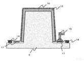
- Step (II) is a step of covering and heating the region including the single-sided mold and the prepreg with the flexible film 16 and heating and pressurizing the space formed by the single-sided mold 9 and the flexible film 16 under reduced pressure ( FIG. 9).
- a valve 19 is installed as a suction port on a part of the contact surface between the flexible film 16 and the single-sided mold 9, and a vacuum is used to form a molding space (single-sided type and flexible one from the suction port).
- the air present in the space made up of the film is sucked to decompress the molding space.
- the molding space is in a reduced pressure state from the outside, the shaped prepreg itself is in a pressurized state. Further, at this time, from the viewpoint of forming a good design surface, it is preferable to adopt a mode in which a die having a shape corresponding to the single-sided die is pressed.
- the mold is pressed so as to be in close contact with the prepreg surface and then covered with a flexible film together with the mold, or the single-sided mold and the prepreg
- An example is a method in which a region including is covered with a flexible film, and the space formed by the single-sided mold and the flexible film is decompressed, and then the mold is pressed from above the flexible film. Then, by putting it in an autoclave, a hot air oven or the like and heating it, the curing reaction of the thermosetting resin (B) proceeds to obtain a mammography apparatus photographing stand.
- the gas existing in the molding space is sucked and depressurized, so the air between the shaped prepreg layers and the air between the prepreg and the single-sided surface is also removed, and the resulting mammography apparatus imaging stand Void formation is suppressed, and there is an effect of having good mechanical properties and surface quality. Furthermore, it is preferable to perform heating and pressurization in an autoclave because the formation of voids is further suppressed. More preferably, in the step (I), it is preferable that the substrate is shaped into a single-sided mold by an automatic laminating apparatus.
- a unidirectional carbon fiber composite material requires a process of cutting into a complicated shape in advance so that a large-sized base material can be formed without any problems.
- an automatic laminating device it is possible to form a single-sided mold with a narrow width without using a cutting process. Since variation can also be reduced, it is preferable.
- unidirectional carbon fiber prepreg As a unidirectional carbon fiber prepreg, “Torayca (registered trademark) prepreg” P3252S-10 manufactured by Toray Industries, Inc. was prepared.
- Carbon fiber fabric prepreg As a carbon fiber fabric prepreg, “Torayca (registered trademark) prepreg” F6347B-05P manufactured by Toray Industries, Inc. was prepared.
- the aluminum equivalent is preferably 0.5 mmAL or less at any point regardless of the conditions of the X-ray irradiation tube voltage, and the X-ray irradiation tube voltage is 20 kV to 60 kV.
- the X-ray irradiation tube voltage may be 20 kV or 60 kV and 0.5 mmAL or less.
- Example 1 12 layers of unidirectional carbon fiber prepregs 13 were laminated on the single-sided mold 9 shown in FIG.
- the single-sided mold 9 includes an A surface 10 that forms the top surface including the X-ray irradiation surface, three surfaces (B surface 11) that form the standing wall on the side surface of the imaging table 1A for the mammography apparatus, and an imaging table 1A for the mammography apparatus. And a C surface 12 that forms the bottom surface of.
- the step of forming the unidirectional carbon fiber prepreg 13 on the single-sided die 9 was carried out by a method of laminating the single-sided die 9 on each surface of the single-sided die 9 one by one.
- the unidirectional carbon fiber prepreg 13 is laminated on the B surface 11 (FIG. 5), and then the unidirectional carbon fiber prepreg 13 is laminated on the A surface 10 and the C surface 12 in a laminated configuration [0/90] 3S. (FIG. 6) Finally, the unidirectional carbon fiber prepreg 13 was laminated on the B surface 11 (FIG. 7).
- the x direction shown in FIG. 5 coincides with the 0 ° direction.
- [0/90] indicates that two layers are laminated so that the fiber orientation directions of the unidirectional carbon fiber prepreg 13 are the 0 ° direction and the 90 ° direction.
- the subscript 3S indicates that the two layers are repeated three times and further symmetrically stacked. Therefore, it means that a total of 12 unidirectional carbon fiber prepregs 13 are laminated.
- the cutting pattern of the unidirectional carbon fiber prepreg 13 in the present laminated structure includes a cutting pattern laminated on the B surface 11 and a 0 ° direction cutting pattern laminated on the A surface 10 and the C surface 12 (the carbon fibers are oriented in the x direction).
- a valve 19 having a backflow prevention valve as a suction port on the bleeder 17
- the single-sided mold was covered with the flexible film 16, and the sealing material 18 and the flexible film 16 were brought into close contact with each other.
- a vacuum pump is connected to the valve 19 which is a suction port, and air in a molding space (a space including a region where the unidirectional carbon fiber prepreg 13 formed by a single-sided mold and a flexible film 16 is laminated).
- a molding space a space including a region where the unidirectional carbon fiber prepreg 13 formed by a single-sided mold and a flexible film 16 is laminated.
- a single-sided mold is put into the autoclave apparatus, heated at a rate of 2.5 ° C./min under the condition of a pressure of 3 atm, and held for 90 minutes after reaching 130 ° C. to heat and pressurize the prepreg.
- the thermosetting resin composition in 13 was cured.
- the molded product was removed from the single-sided mold 9,
- the obtained mammography apparatus photographing stand 1A (FIGS. 8a, 8b and 8c) has an opening 8, and an aluminum alloy connecting member 14 is inserted through the opening to form an opening 2 which faces each other.
- a two-component epoxy adhesive (FIGS. 8a and 8b)
- the X-ray irradiation tube voltage was 60 kV, and the conditions were 0.17 mmAL and 20 kV. And was 0.14 mmAL.
- a rectangular test piece was cut out using an NC router, and the specific bending elasticity calculated by the method described in [Calculation of specific bending elastic modulus] above. The rate was 2.70.
- the thickness of the A surface (X-ray irradiation surface 5) of the obtained mammography apparatus photographing stand 1A was 1.28 mm.
- Example 2 A unidirectional carbon fiber prepreg 13 was laminated by using the same single-sided die as in Example 1 and setting the laminated structure to [0/90/0/90/0/0/90/0/90/0] from the die surface side. Thereafter, a mammography apparatus photographing stand 1B was obtained in the same manner as in Example 1 except that one carbon fiber woven prepreg was laminated on the outermost layers of all of the A surface 10, the B surface 11, and the C surface 12. . The obtained mammography apparatus photographing stand 1B has an opening 8, and a joining member 14 made of an aluminum alloy is joined in the same manner as in (Example 1) (FIGS. 8a, 8b and 8c).
- the aluminum equivalent of the A surface (X-ray irradiation surface 5) was measured.
- the X-ray irradiation tube voltage was 60 kV, 0.18 mmAL, and 20 kV, 0.15 mmAL. It was.
- Example 2 the specific bending elastic modulus obtained in the same manner as in Example 1 for the obtained mammography apparatus photographing stand 1B was 2.75. Moreover, the thickness of the A surface (X-ray irradiation surface 5) of the obtained imaging table 1B for mammography apparatuses was 1.30 mm.
- the unidirectional carbon fiber prepreg 13 was laminated with a laminated configuration [0/90] 3S to obtain a prepreg laminate 15.
- the prepreg laminate 15 has a square shape, and the unidirectional carbon fiber prepreg 13 has one cutting pattern. Therefore, there was little waste such as scraps.
- the laminate 15 is arranged in a pair of double-sided molds of a female mold 20 and a male mold 21 shown in FIG. 10, and heated and pressurized at 130 ° C. for 90 minutes at a surface pressure of 1.0 MPa using a hydraulic press machine, A molded product was obtained. The surface pressure was calculated from the area of the laminate before molding (projected area viewed from the lamination direction).
- the standing wall surface is trimmed with an NC router so that the x direction in FIG. 11a coincides with the 0 ° direction, and each of the A surface 10 and the B surface 11 erected on the three outer sides thereof.
- a carbon fiber composite material member 22a (first member 22) forming a part was obtained (FIGS. 11a and 11b).
- an ABS resin (“Toyolac (registered trademark)" 600-309, manufactured by Toray Industries, Inc.) is formed into a 3 mm thick resin sheet by extrusion molding, and the outer periphery 3 A molded product with a standing wall surface was obtained.
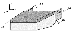
- Resin member which processes the standing wall surface of the molded product with an NC router forms part of each of C surface 12 and B surface 11 erected on the three outer sides thereof, and has a stepped portion on the B surface 11 side 23a (second member 23) was obtained (FIGS. 12a and 12b).
- the carbon fiber composite material member 22a and the resin member 23a are joined at the stepped portion as shown in FIGS.
- the obtained imaging stand 1C for mammography apparatus has an opening 8 on one side, and a joining member 14 made of aluminum alloy is joined in the same manner as in (Example 1), assembled to the mammography apparatus main body 2, and further When a mammography image was taken, a good image could be obtained.
- the aluminum equivalent of the A surface was measured.
- the X-ray irradiation tube voltage was 60 kV, 0.17 mAL, and 20 kV, 0.14 mmAL. It was.
- required similarly to (Example 1) about the obtained imaging stand 1C for mammography apparatuses was 2.71.
- the thickness of the A surface (X-ray irradiation surface 5) of the obtained imaging table 1C for mammography apparatuses was 1.28 mm.
- Example 4 A unidirectional carbon fiber prepreg 13 is laminated in a laminated configuration [0/90/0/90/0/0/90/0/90/0], and a single layer of carbon fiber woven prepreg is laminated on one side of the laminate. 15 was obtained.
- a carbon fiber composite material member 22b (first member 22) was obtained in the same manner as in Example 3 except that the carbon fiber woven prepreg surface was brought into contact with the female mold surface and heated and pressurized with a double-sided mold.
- a polycarbonate resin ("Iupilon (registered trademark)" E-2000, manufactured by Mitsubishi Engineering Plastics Co., Ltd.) is molded into a 3 mm thick resin sheet by extrusion molding, and the resin sheet is vacuum molded. A molded product having three standing walls was obtained.
- Resin member which processes the standing wall surface of the molded product with an NC router forms part of each of C surface 12 and B surface 11 erected on the three outer sides thereof, and has a stepped portion on the B surface 11 side 23b (second member 23) was obtained.
- the carbon fiber composite material member 22b and the resin member 23b are joined at the stepped portion as shown in FIGS. 13a, 13b, and 13c using a two-component epoxy adhesive, and the photographic stand 1D for mammography apparatus Got.
- the mammography apparatus photographing stand 1D has an opening 8, and a joining member 14 made of an aluminum alloy is joined in the same manner as in (Example 1) (FIGS. 13a, 13b and 13c), and the mammography apparatus body 2 When a mammography image was further photographed, it was possible to obtain a good image.
- the aluminum equivalent of surface A (X-ray irradiation surface 5) was measured.
- the X-ray irradiation tube voltage was 60 kV, 0.18 mAL, and 20 kV, 0.15 mmAL. It was.
- photography stand 1D for mammography apparatuses was 2.75.
- the thickness of the A surface (X-ray irradiation surface 5) of the obtained imaging table 1D for mammography apparatuses was 1.30 mm.
- Example 5 The unidirectional carbon fiber prepreg 13 was cut into a width of 10 mm with the longitudinal direction and the fiber orientation direction being matched to obtain a unidirectional carbon fiber tape.
- the unidirectional carbon fiber tape is set in an automatic laminating apparatus, and using the same single-sided mold 9 as in Example 1, [0/90] 3S from the mold surface side, and using an automatic laminating apparatus, shaping is performed. did.
- the shaping step the unidirectional carbon fiber tape was shaped with a uniform thickness at the corners without forming a seam on the standing wall surface. Otherwise, a mammography apparatus photographing stand 1E was obtained in the same manner as in (Example 1).
- the mammography apparatus photographing stand 1E has an opening 8, and an aluminum alloy connecting member 14 is joined in the same manner as in the first embodiment (FIGS. 8a, 8b, and 8c), and is attached to the mammography apparatus body 2.
- FIGS. 8a, 8b, and 8c first embodiment
- the aluminum equivalent of surface A (X-ray irradiation surface 5) was measured.
- the X-ray irradiation tube voltage was 0.17 mmAL under 60 kV conditions and 0.14 mmAL under 20 kV conditions. It was.
- photography stand 1E for mammography apparatuses obtained was 2.68.
- the thickness of the A surface (X-ray irradiation surface 5) of the obtained mammography apparatus photographing stand 1E was 1.28 mm.
- a mammography apparatus photographing stand 1F was obtained in the same manner as in (Example 1) except that the carbon fiber fabric prepreg 7 layers were used for shaping into a mold.
- the mammography apparatus imaging stand 1F has an opening 8, and a connecting member 14 made of an aluminum alloy is joined in the same manner as in (Example 1) (FIGS. 8a, 8b and 8c), and is attached to the mammography apparatus body 2.
- a connecting member 14 made of an aluminum alloy is joined in the same manner as in (Example 1) (FIGS. 8a, 8b and 8c), and is attached to the mammography apparatus body 2.
- the X-ray irradiation tube voltage was 60 kV, 0.20 mmAL, and 20 kV, 0.16 mmAL. It was. Moreover, the specific bending elastic modulus calculated
- Table 1 summarizes the characteristics of the imaging table for mammography devices obtained in the above-described examples and comparative examples. It was confirmed that the mammography apparatus imaging stand 1A is a mammography apparatus imaging stand that has a thinner X-ray irradiation surface and higher rigidity and X-ray permeability than the mammography apparatus imaging stand 1F. Further, after the surfaces of the mammography apparatus photographing stand 1A and the mammography apparatus photographing stand 1B were polished with sandpaper to expose the carbon fiber, the surface was traced with bare hands, and the mammography apparatus photographing stand 1A was made of carbon fiber fluff. However, no pain was felt on the mammography apparatus photographing stand 1B.
- the mammography apparatus imaging stand 1C has the same rigidity and X-ray transparency as compared with the mammography apparatus imaging table 1A, but can reduce the cutting pattern of the base material and can be manufactured with high productivity. did it.
- the mammography apparatus imaging stand 1E was able to be manufactured with high productivity by automating the single-sided lamination process as compared with the mammography apparatus imaging table 1A.
- Example 11 As a resin sheet, an acid-modified polypropylene resin (“Admer (registered trademark)” QB510, manufactured by Mitsui Chemicals, Inc.) was used to obtain a resin sheet having a thickness of 1.2 mm using an extruder.
- the resin sheet 25 and the carbon fiber fabric prepreg 24 were laminated on the single-sided mold 9 shown in FIG.
- the single-sided mold 9 includes an A surface 10 that forms the top surface including the X-ray irradiation surface, three surfaces (B surface 11) that form the standing wall on the side surface of the imaging table 1A for the mammography apparatus, and an imaging table 1A for the mammography apparatus. And a C surface 12 that forms the bottom surface of.
- the step of forming the carbon fiber woven prepreg 24 and the resin sheet 25 on the single-sided die 9 was performed by a method of laminating the single-sided die 9 one by one.
- the carbon fiber fabric prepreg 24 is laminated on the B surface 11 (FIG. 14), and then the carbon fiber fabric prepreg 24 is formed on the A surface 10 and the C surface 12, respectively, and the carbon fiber fabric prepreg 2 layers are formed on the A surface 10.
- the resin sheet 25 has the same size as the A surface.
- the cutting pattern of the carbon fiber fabric prepreg 24 in the present laminated configuration includes three types of cutting patterns that are stacked on the A surface 10, a cutting pattern that is stacked on the B surface 11, and a cutting pattern that is stacked on the C surface 12.
- the outer periphery of the region where the carbon fiber woven prepreg 24 is laminated is covered with a sealing material 18 (the flexible film 16 and the mold are brought into close contact with each other and the inside of the mold is sealed), and then the prepreg laminated body 15 A bleeder 17 (acting as a spacer for air passage) made of a thick non-woven fabric was disposed on the outer periphery.
- a valve 19 having a backflow prevention valve as a suction port on the bleeder 17
- the single-sided mold was covered with the flexible film 16, and the sealing material 18 and the flexible film 16 were brought into close contact with each other.
- a vacuum pump is connected to the valve 19 which is a suction port, and a molding space (a space including a region in which a carbon fiber woven prepreg 24 and a resin sheet 25 formed from a single-sided mold and a flexible film 16 are laminated). The inside air was sucked to reduce the pressure in the molding space.
- a single-sided mold is put into the autoclave apparatus, heated at a rate of 2.5 ° C./min under the condition of a pressure of 3 atm, and maintained for 90 minutes after reaching 130 ° C.
- the thermosetting resin composition in the fiber fabric prepreg 24 was cured.
- the molded product was removed from the single-sided mold 9, and the end surface was trimmed with an NC router to obtain a mammography apparatus photographing stand 1G.
- the obtained mammography apparatus photographing stand 1G has an opening, and an aluminum alloy connecting member 14 is inserted through the opening to form an opening and connect to the respective inner wall surfaces of the two standing wall portions facing each other.
- the member 14 was joined with a two-component epoxy adhesive (FIGS. 17a, 17b and 17c).
- a two-component epoxy adhesive FIGS. 17a, 17b and 17c.
- Example 12 As a resin sheet, an acid-modified polypropylene resin (“Admer (registered trademark)” QB510, manufactured by Mitsui Chemicals, Inc.) was used to obtain a resin sheet having a thickness of 1.2 mm using an extruder. Two sets of two carbon fiber woven prepregs were prepared and laminated on both sides of the resin sheet to obtain a laminate. The laminate is placed in a pair of double-sided dies 20 and 21 shown in FIG. 10, and heated and pressurized at 130 ° C. for 90 minutes at a surface pressure of 1.0 MPa using a hydraulic press. I got a product. The surface pressure was calculated from the area of the laminate before molding (projected area viewed from the lamination direction).
- Admer registered trademark
- QB510 manufactured by Mitsui Chemicals, Inc.
- the outer periphery of the molded product was trimmed with an NC router to obtain a first member 22H having a skin material made of a carbon fiber composite material and a core material made of a resin sheet (FIGS. 18a and 18b).
- a polycarbonate resin pellet (“Panlite (registered trademark)” G-3420, manufactured by Teijin Ltd.) as a raw material
- the second member 23H having the shape shown in FIGS. 12a and 12b is formed using an injection molding machine. Molded.
- the obtained first member 22H and second member 23H were joined using a two-component epoxy adhesive to obtain an imaging table 1H for a mammography apparatus.
- the obtained mammography apparatus photographing stand 1H has an opening, and an aluminum alloy connecting member 14 is joined in the same manner as in Example 11 (FIGS. 19a, 19b and 19c).
- an aluminum alloy connecting member 14 is joined in the same manner as in Example 11 (FIGS. 19a, 19b and 19c).
- good images could be obtained.
- the aluminum equivalent of the X-ray irradiated surface was measured.
- the X-ray irradiation tube voltage was 0.19 mmAL under the 60 kV condition and 0.15 mmAL under the 20 kV condition.
- Example 13 Acrylic foam (“Formac (registered trademark)” S # 1000, manufactured by Sekisui Chemical Co., Ltd.) was cut out as a resin sheet to obtain a resin sheet having a thickness of 1.5 mm.
- This resin sheet and the unidirectional carbon fiber prepreg were laminated with [0/90 / resin sheet / 90/0] to obtain a laminate.
- the x direction shown in FIG. 19a is the 0 ° direction. Except using this laminated body, it was carried out similarly to (Example 12), and obtained the imaging stand 1I for mammography apparatuses which consists of the 1st member 22I and the 2nd member 23I.
- the obtained mammography apparatus photographing stand 1I has an opening, and an aluminum alloy connecting member 14 is joined in the same manner as in Example 12 (FIGS. 19a, 19b, and 19c), and the mammography apparatus When assembled to the main body 2 and further mammographic images were taken, good images could be obtained.
- the aluminum equivalent of the X-ray irradiated surface was measured.
- the X-ray irradiation tube voltage was 0.12 mmAL under 60 kV conditions and 0.11 mmAL under 20 kV conditions.
- a rectangular test piece was cut out using an NC router with the x direction of the X-ray irradiation surface of the first member 22I in the obtained imaging table 1I for the mammography apparatus as a longitudinal direction, and [specific bending elastic modulus Ep
- the specific bending elastic modulus calculated by the method described in [Calculation] was 7.13.
- Example 14 A polymethacrylimide foam (“ROHACELL (registered trademark)” 110HP, manufactured by Daicel Evonik Co., Ltd.) was cut out as a resin sheet to obtain a resin sheet having a thickness of 1.5 mm.
- This resin sheet and the unidirectional carbon fiber prepreg were laminated with [0/90 / resin sheet / 90/0] to obtain a laminate.
- the 0 ° direction coincides with the fiber orientation direction of the unidirectional carbon fiber
- the x direction shown in FIG. 19 is the 0 ° direction.
- an ABS resin (“Toyolac (registered trademark)” 600-309, manufactured by Toray Industries, Inc.) is produced by extrusion molding to produce a resin sheet having a thickness of 3 mm. A molded product having was obtained.
- the standing wall surface of the molded product was processed with an NC router to obtain a second member 23J having a stepped portion at the end of the standing wall.
- the obtained first member 22J and second member 23J were joined using a two-component epoxy adhesive to obtain an imaging table 1J for a mammography apparatus.
- the obtained mammography apparatus photographing stand 1J has an opening, and a joining member 14 made of an aluminum alloy is joined in the same manner as in Example 12 (FIGS. 19a, 19b, and 19c). When assembled to the main body 2 and further mammographic images were taken, good images could be obtained. According to the method described in [Measurement of Aluminum Equivalent], the aluminum equivalent of the X-ray irradiated surface was measured.
- the X-ray irradiation tube voltage was 0.12 mmAL under 60 kV conditions and 0.10 mmAL under 20 kV conditions.
- a rectangular test piece was cut out using an NC router with the x direction of the X-ray irradiation surface of the first member 22J in the obtained mammography apparatus imaging table 1J as the longitudinal direction, and [specific bending elastic modulus Ep of The specific flexural modulus calculated by the method described in [Calculation] was 7.54.
- Example 15 The resin sheet used in the unidirectional carbon fiber prepreg and (Example 14) was laminated with [0/90 / resin sheet / 90/0], and one layer of the carbon fiber woven prepreg was laminated on one side thereof to obtain a laminate.
- the x direction shown in FIG. 19a is the 0 ° direction.
- the carbon fiber woven prepreg surface is placed in a pair of double-sided molds 20 and 21 shown in FIG. 10 in contact with the female mold surface, and a surface pressure of 1.30 ° C. for 90 minutes using a hydraulic press. Heated and pressurized at 0 MPa to obtain a molded product.
- the outer periphery of the molded product was trimmed with an NC router to obtain a first member 22K having a skin material made of a carbon fiber composite material and a core material made of a resin sheet.
- the surface pressure was calculated from the area of the laminate before molding (projected area viewed from the lamination direction).
- the mammography apparatus photographing stand 1K including the first member 22K and the second member 23K was obtained by the same method as in (Example 14).
- the obtained imaging table 1K for mammography apparatus has an opening, and a joining member 14 made of aluminum alloy is joined in the same manner as in Example 12 (FIGS. 19a, 19b and 19c), and the mammography apparatus When assembled to the main body 2 and further mammographic images were taken, good images could be obtained.
- the X-ray irradiation tube voltage was 0.13 mmAL under 60 kV conditions and 0.12 mmAL under 20 kV conditions.
- Example 11 Using the same single-sided mold 9 as in Example 11, seven layers of carbon fiber woven prepregs were shaped from the mold surface into a mold. Otherwise, a mammography apparatus photographing stand 1L was obtained in the same manner as in Example 11. The obtained mammography apparatus photographic stand 1L has an opening, and a joining member 14 made of aluminum alloy is joined in the same manner as in Example 11 (FIGS. 17a, 17b, and 17c), and the mammography apparatus When the mammography image was taken with the main body 2 assembled, the image could be obtained without any problem. According to the method described in [Measurement of Aluminum Equivalent], the aluminum equivalent of the A surface (X-ray irradiation surface 5) was measured.
- the X-ray irradiation tube voltage was 60 kV, 0.20 mmAL, and 20 kV, 0.16 mmAL. It was. Further, with the x direction of the obtained mammography apparatus photographing stand 1L as the longitudinal direction, a rectangular test piece was cut out using an NC router, and the specific bending calculated by the method described in [Calculation of specific bending elastic modulus Ep] The elastic modulus was 2.46.
- Example 16 Spinning, firing treatment, and surface oxidation treatment were carried out from a copolymer containing polyacrylonitrile as a main component to obtain continuous carbon fibers having a total number of 12,000 single yarns.
- the characteristics of this continuous carbon fiber were a single fiber diameter of 7 ⁇ m, a density of 1.8 g / cm 3 , a tensile strength of 4600 MPa, and a tensile elastic modulus of 220 GPa.
- the obtained continuous carbon fiber was cut into 6 mm with a cartridge cutter to obtain chopped carbon fiber.
- a dispersion liquid having a concentration of 0.1% by mass composed of water and a surfactant (polyoxyethylene lauryl ether (trade name), manufactured by Nacalai Tex Co., Ltd.) was prepared, and the dispersion liquid and chopped carbon fiber were made into paper.
- the papermaking apparatus includes a cylindrical container having a diameter of 1000 mm having an opening cock at the bottom of the container as a dispersion tank, and a linear transport section (inclination angle of 30 °) that connects the dispersion tank and the papermaking tank.
- a stirrer is attached to the opening on the upper surface of the dispersion tank, and chopped carbon fiber and dispersion liquid (dispersion medium) can be introduced through the opening.
- the papermaking tank is provided with a mesh conveyor having a papermaking surface having a width of 500 mm at the bottom, and the mesh conveyor can carry the resulting carbon fiber substrate (papermaking substrate). Papermaking was performed at a carbon fiber concentration of 0.05% by mass in the dispersion. The paper-made carbon fiber substrate was dried in a drying furnace at 200 ° C. for 30 minutes to obtain a reinforcing fiber mat. The obtained basis weight was 25 g / m 2 .
- a resin sheet having a thickness of 1.5 mm and a density of 0.2 g / cm 3 was obtained through the following steps (I) to (V). From the cross-sectional observation, it was confirmed that the obtained resin sheet had voids in which the reinforcing fibers were dispersed in a substantially monofilament shape and randomly, and the reinforcing fibers were columnar supports.
- step (I) The laminate is placed in a press mold cavity preheated to 230 ° C. and the mold is closed.
- step (II) Next, after holding for 120 seconds, a pressure of 3 MPa is applied and the pressure is further held for 60 seconds.
- step (III) After step (II), the mold cavity is opened, a metal spacer is inserted at the end thereof, and the thickness when the structure is obtained is adjusted to 1.5 mm.
- step (IV) Thereafter, the mold cavity is fastened again, and the cavity temperature is cooled to 50 ° C. while maintaining the pressure.
- (V) Open the mold and take out the resin sheet. This resin sheet and the unidirectional carbon fiber prepreg were laminated with [0/90 / resin sheet / 90/0] to obtain a laminate.
- the x direction shown in FIG. 19a is the 0 ° direction.
- the molded product was obtained by placing in a pair of double-sided dies of a female die 20 and a male die 21 shown in FIG. 10 and heating and pressing at 160 ° C. for 30 minutes and a surface pressure of 3.0 MPa using a hydraulic press.
- the outer periphery of the molded product was trimmed with an NC router to obtain a first member 22M having a skin material made of a carbon fiber composite material and a core material made of a resin sheet.
- the surface pressure was calculated from the area of the laminate before molding (projected area viewed from the lamination direction).
- the mammography apparatus photographing stand 1M including the first member 22M and the second member 23M was obtained in the same manner as in (Example 14).
- the obtained mammography apparatus photographing stand 1M has an opening, and a joining member 14 made of an aluminum alloy is joined in the same manner as in (Example 12) (FIGS. 19a, 19b and 19c). When assembled to the main body 2 and further mammographic images were taken, good images could be obtained.
- the aluminum equivalent of the X-ray irradiated surface was measured.
- the X-ray irradiation tube voltage was 0.12 mmAL under 60 kV conditions and 0.10 mmAL under 20 kV conditions.
- a rectangular test piece was cut out using an NC router with the x direction of the X-ray irradiation surface of the first member 22M in the obtained imaging table 1M for the mammography apparatus as a longitudinal direction, and [specific bending elastic modulus Ep of The specific bending elastic modulus calculated by the method described in [Calculation] was 7.70.
- Example 17 The reinforcing fiber mat and resin sheet produced in (Example 16) were [resin film / reinforcing fiber mat / resin film / reinforcing fiber mat / resin film / reinforcing fiber mat / resin film / reinforcing fiber mat / reinforcing fiber mat / resin.
- a laminate having the order of “film / reinforcing fiber mat / resin film / reinforcing fiber mat / resin film / reinforcing fiber mat / resin film” was prepared.
- a resin sheet having a thickness of 3.0 mm and a density of 0.2 g / cm 3 was obtained through the following steps (I) to (V). From the cross-sectional observation, it was confirmed that the obtained resin sheet had voids in which the reinforcing fibers were dispersed in a substantially monofilament shape and randomly, and the reinforcing fibers were columnar supports.
- step (I) The laminate is placed in a press mold cavity preheated to 230 ° C. and the mold is closed.
- step (II) Next, after holding for 120 seconds, a pressure of 3 MPa is applied and the pressure is further held for 60 seconds.
- step (III) After step (II), the mold cavity is opened, a metal spacer is inserted into the end thereof, and the thickness when the structure is obtained is adjusted to 3.0 mm.
- step (IV) Thereafter, the mold cavity is fastened again, and the cavity temperature is cooled to 50 ° C. while maintaining the pressure.
- (V) Open the mold and take out the resin sheet.
- This resin sheet is placed in a pair of double-sided molds of a female mold 20 and a male mold 21 shown in FIG. 10, and heated and pressurized at 180 ° C. and a surface pressure of 3.0 MPa for 5 minutes using a hydraulic press machine.
- the resin sheet was shaped by cooling to 50 ° C. while being held.
- One layer of a carbon fiber woven prepreg is laminated on the female side of the resin sheet after shaping, and is again placed in a pair of double-sided molds shown in FIG. 10, and the surface pressure is maintained at 130 ° C. for 90 minutes using a hydraulic press.
- the molded product was obtained by heating and pressing at 1.0 MPa.
- the outer periphery of the molded product was trimmed with an NC router to obtain a first member 22N having a two-layer structure of a skin material made of a carbon fiber composite material and a resin sheet.
- the surface pressure was calculated from the area of the laminate before molding (projected area viewed from the lamination direction).
- a resin sheet having a thickness of 4.5 mm is produced by extrusion molding of ABS resin (“Toyolac (registered trademark)” 600-309, manufactured by Toray Industries, Inc.), and the resin sheet is stood by vacuum molding. A molded product having a wall surface was obtained.
- the standing wall surface of the molded product was processed with an NC router to obtain a second member 23N having a step at the end of the standing wall.
- the obtained first member 22N and second member 23N were joined using a two-component epoxy adhesive to obtain an imaging table 1N for a mammography apparatus.
- the obtained mammography apparatus photographic stand 1N has an opening, and a joining member 14 made of an aluminum alloy is joined in the same manner as in Example 12 (FIGS. 20a, 20b, and 20c), and the mammography apparatus When assembled to the main body 2 and further mammographic images were taken, good images could be obtained.
- the X-ray irradiation tube voltage was 0.10 mmAL under 60 kV conditions and 0.09 mmAL under 20 kV conditions.
- a rectangular test piece was cut out using an NC router with the x direction of the X-ray irradiation surface of the first member 22M in the obtained imaging table 1M for the mammography apparatus as a longitudinal direction, and [specific bending elastic modulus Ep of The specific bending elastic modulus calculated by the method described in [Calculation] was 11.1.
- Table 2 summarizes the characteristics of the mammography apparatus photographing stand obtained in the above examples and comparative examples. From a comparison between the mammography apparatus imaging table 1G and the mammography apparatus imaging table 1L, it was confirmed that the X-ray transmission was good while the bending rigidity of the X-ray irradiation surface was equal. From a comparison between the mammography apparatus imaging platform 1I and the mammography apparatus imaging platform 1J, it was confirmed that the density unevenness in the X-ray irradiation region was reduced. After the X-ray irradiated surfaces of the mammography apparatus imaging table 1J and the mammography apparatus imaging table 1K are polished with sandpaper to expose the carbon fiber, the surface is traced with bare hands.
- the mammography apparatus imaging table 1J is carbon fiber. While the fluff of the nose pierced the finger and felt pain, the mammography apparatus photographing stand 1K felt no pain. Further, it was confirmed that the mammography apparatus imaging tables 1M and 1N exhibited excellent X-ray transparency and bending rigidity of the X-ray irradiation surface as compared with the mammography apparatus imaging table 1H.
- a thin-walled, high-rigidity mammography photographing stand can be provided.
- Such an imaging table is thin and thus has improved X-ray transmission, thereby reducing the exposure dose of the subject. Since the imaging table is highly rigid, deflection due to a load applied during imaging is reduced, so that the accuracy of the captured image is improved.
- the imaging table has a resin sheet, X-ray transmission is improved and the exposure dose of the subject can be reduced, and because it has a skin material made of a carbon fiber composite material, it exhibits high rigidity and reduces deflection due to load load during imaging. Therefore, the accuracy of the captured image is improved.
- Imaging stand for mammography apparatuses 2
- Mammography apparatus main body 3
- Compression board 4
- X-ray generation part 5
- X-ray irradiation surface 6
- Bottom face of imaging stand for mammography apparatuses 7
- Standing wall part 8
- Opening part 9
- Single-sided type 10 A surface 11
- connecting member 15
- prepreg laminate 16
- flexible film 17
- bleeder 18 sealing material 19
- valve 20 female mold 21 male mold 22
- first member 23
- carbon fiber prepreg 25 resin sheet 26 Steps on the top
Landscapes
- Health & Medical Sciences (AREA)
- Life Sciences & Earth Sciences (AREA)
- Engineering & Computer Science (AREA)
- Medical Informatics (AREA)
- Pathology (AREA)
- Heart & Thoracic Surgery (AREA)
- Veterinary Medicine (AREA)
- Biophysics (AREA)
- High Energy & Nuclear Physics (AREA)
- Public Health (AREA)
- Nuclear Medicine, Radiotherapy & Molecular Imaging (AREA)
- Optics & Photonics (AREA)
- General Health & Medical Sciences (AREA)
- Radiology & Medical Imaging (AREA)
- Biomedical Technology (AREA)
- Physics & Mathematics (AREA)
- Molecular Biology (AREA)
- Surgery (AREA)
- Animal Behavior & Ethology (AREA)
- Mechanical Engineering (AREA)
- Chemical & Material Sciences (AREA)
- Composite Materials (AREA)
- Dentistry (AREA)
- Oral & Maxillofacial Surgery (AREA)
- Apparatus For Radiation Diagnosis (AREA)
- Measurement Of Radiation (AREA)
- Analysing Materials By The Use Of Radiation (AREA)
Abstract
Priority Applications (6)
| Application Number | Priority Date | Filing Date | Title |
|---|---|---|---|
| CA3094728A CA3094728A1 (fr) | 2018-03-23 | 2019-03-20 | Table d'imagerie, table d'imagerie d'appareil de mammographie et son procede de fabrication, et appareil de mammographie |
| CN201980020746.XA CN111936052A (zh) | 2018-03-23 | 2019-03-20 | 拍摄台、钼靶检查装置用拍摄台及其制造方法及钼靶检查装置 |
| JP2019520764A JP7439513B2 (ja) | 2018-03-23 | 2019-03-20 | マンモグラフィ装置用撮影台およびその製造方法およびマンモグラフィ装置 |
| EP19770384.6A EP3769685A4 (fr) | 2018-03-23 | 2019-03-20 | Table d'imagerie, table d'imagerie d'appareil de mammographie et son procédé de fabrication, et appareil de mammographie |
| KR1020207027274A KR20200134241A (ko) | 2018-03-23 | 2019-03-20 | 촬영대, 맘모그라피 장치용 촬영대 및 그 제조 방법 및 맘모그라피 장치 |
| US16/982,677 US11389121B2 (en) | 2018-03-23 | 2019-03-20 | Imaging table, mammography apparatus imaging table and manufacturing method therefor, and mammography apparatus |
Applications Claiming Priority (4)
| Application Number | Priority Date | Filing Date | Title |
|---|---|---|---|
| JP2018-055836 | 2018-03-23 | ||
| JP2018-055840 | 2018-03-23 | ||
| JP2018055836 | 2018-03-23 | ||
| JP2018055840 | 2018-03-23 |
Publications (1)
| Publication Number | Publication Date |
|---|---|
| WO2019182076A1 true WO2019182076A1 (fr) | 2019-09-26 |
Family
ID=67987855
Family Applications (1)
| Application Number | Title | Priority Date | Filing Date |
|---|---|---|---|
| PCT/JP2019/011937 Ceased WO2019182076A1 (fr) | 2018-03-23 | 2019-03-20 | Table d'imagerie, table d'imagerie d'appareil de mammographie et son procédé de fabrication, et appareil de mammographie |
Country Status (8)
| Country | Link |
|---|---|
| US (1) | US11389121B2 (fr) |
| EP (1) | EP3769685A4 (fr) |
| JP (1) | JP7439513B2 (fr) |
| KR (1) | KR20200134241A (fr) |
| CN (1) | CN111936052A (fr) |
| CA (1) | CA3094728A1 (fr) |
| TW (1) | TW202002900A (fr) |
| WO (1) | WO2019182076A1 (fr) |
Cited By (2)
| Publication number | Priority date | Publication date | Assignee | Title |
|---|---|---|---|---|
| JP2022122806A (ja) * | 2021-02-10 | 2022-08-23 | 東芝Itコントロールシステム株式会社 | 放射線検査装置 |
| WO2023032893A1 (fr) * | 2021-09-01 | 2023-03-09 | 東レ株式会社 | Élément de transmission de rayons x |
Families Citing this family (1)
| Publication number | Priority date | Publication date | Assignee | Title |
|---|---|---|---|---|
| CN112519374B (zh) * | 2020-11-26 | 2023-03-03 | 欧瑞特佳(三河)科技有限公司 | 一种透x光医用板材的制备方法、板材和应用 |
Citations (11)
| Publication number | Priority date | Publication date | Assignee | Title |
|---|---|---|---|---|
| WO2000056539A1 (fr) * | 1999-03-23 | 2000-09-28 | Toray Industries, Inc. | Materiau a base de fibres renforçant un composite, preforme et procede de production de matiere plastique renforcee par des fibres |
| JP2003207864A (ja) * | 2002-01-10 | 2003-07-25 | Konica Corp | 放射線画像撮影用カセッテ及び乳房撮影用カセッテ |
| JP2005313613A (ja) * | 2004-03-29 | 2005-11-10 | Toray Ind Inc | 繊維強化樹脂製サンドイッチパネル |
| JP2009230000A (ja) * | 2008-03-25 | 2009-10-08 | Toray Ind Inc | 放射線画像撮影用カセッテおよびその製造方法 |
| JP2010035622A (ja) | 2008-07-31 | 2010-02-18 | Toshiba Corp | マンモグラフィ装置 |
| JP2010039267A (ja) | 2008-08-06 | 2010-02-18 | Konica Minolta Medical & Graphic Inc | 医療用カセッテ及び画像形成方法 |
| US20150164449A1 (en) * | 2013-12-17 | 2015-06-18 | Samsung Electronics Co., Ltd. | Mammography apparatus |
| JP2016022061A (ja) * | 2014-07-17 | 2016-02-08 | シャープ株式会社 | 乳房画像撮影装置 |
| JP2017122382A (ja) * | 2015-12-25 | 2017-07-13 | 東レ株式会社 | 止水板 |
| JP2018055840A (ja) | 2016-09-26 | 2018-04-05 | 東芝ライテック株式会社 | 照明システム |
| JP2018055836A (ja) | 2016-09-26 | 2018-04-05 | 日産自動車株式会社 | 非水電解質二次電池用正極 |
Family Cites Families (11)
| Publication number | Priority date | Publication date | Assignee | Title |
|---|---|---|---|---|
| JPS60236634A (ja) * | 1984-05-10 | 1985-11-25 | 三菱レイヨン株式会社 | 放射線診断装置用天板 |
| US5960057A (en) * | 1997-10-17 | 1999-09-28 | Southeastern Universities Research Assn. | Radiology utilizing a gas multiwire detector with resolution enhancement |
| JP5126405B2 (ja) * | 2004-03-29 | 2013-01-23 | 東レ株式会社 | 繊維強化樹脂製サンドイッチパネルの製造方法 |
| DE102004034239A1 (de) * | 2004-07-15 | 2006-02-02 | Siemens Ag | Gerät zur medizinischen Bildgebung |
| US8331536B2 (en) * | 2009-09-18 | 2012-12-11 | General Electric Company | Apparatus for reducing scattered X-ray detection and method of same |
| DE102010019019A1 (de) * | 2010-05-03 | 2011-11-03 | Siemens Aktiengesellschaft | Verbesserte Brustlagerung bei Mammografieaufnahmen, insbesondere MLO-Aufnahmen |
| JP6222809B2 (ja) * | 2013-05-30 | 2017-11-01 | 東芝メディカルシステムズ株式会社 | マンモグラフィ装置 |
| CN106794637B (zh) * | 2014-10-17 | 2019-05-17 | 东丽株式会社 | 纤维增强复合材料的制造方法、树脂基材及预成型体 |
| US11001011B2 (en) * | 2016-02-23 | 2021-05-11 | Toray Industries, Inc. | Method of producing fiber reinforced composite material |
| CN109691248B (zh) * | 2016-09-26 | 2021-07-30 | 东丽株式会社 | 电子设备壳体及其制造方法 |
| US11800656B2 (en) * | 2016-09-26 | 2023-10-24 | Toray Industries, Inc. | Electronic device housing |
-
2019
- 2019-03-20 EP EP19770384.6A patent/EP3769685A4/fr not_active Withdrawn
- 2019-03-20 US US16/982,677 patent/US11389121B2/en active Active
- 2019-03-20 WO PCT/JP2019/011937 patent/WO2019182076A1/fr not_active Ceased
- 2019-03-20 JP JP2019520764A patent/JP7439513B2/ja active Active
- 2019-03-20 CN CN201980020746.XA patent/CN111936052A/zh active Pending
- 2019-03-20 CA CA3094728A patent/CA3094728A1/fr not_active Abandoned
- 2019-03-20 KR KR1020207027274A patent/KR20200134241A/ko not_active Withdrawn
- 2019-03-22 TW TW108110128A patent/TW202002900A/zh unknown
Patent Citations (11)
| Publication number | Priority date | Publication date | Assignee | Title |
|---|---|---|---|---|
| WO2000056539A1 (fr) * | 1999-03-23 | 2000-09-28 | Toray Industries, Inc. | Materiau a base de fibres renforçant un composite, preforme et procede de production de matiere plastique renforcee par des fibres |
| JP2003207864A (ja) * | 2002-01-10 | 2003-07-25 | Konica Corp | 放射線画像撮影用カセッテ及び乳房撮影用カセッテ |
| JP2005313613A (ja) * | 2004-03-29 | 2005-11-10 | Toray Ind Inc | 繊維強化樹脂製サンドイッチパネル |
| JP2009230000A (ja) * | 2008-03-25 | 2009-10-08 | Toray Ind Inc | 放射線画像撮影用カセッテおよびその製造方法 |
| JP2010035622A (ja) | 2008-07-31 | 2010-02-18 | Toshiba Corp | マンモグラフィ装置 |
| JP2010039267A (ja) | 2008-08-06 | 2010-02-18 | Konica Minolta Medical & Graphic Inc | 医療用カセッテ及び画像形成方法 |
| US20150164449A1 (en) * | 2013-12-17 | 2015-06-18 | Samsung Electronics Co., Ltd. | Mammography apparatus |
| JP2016022061A (ja) * | 2014-07-17 | 2016-02-08 | シャープ株式会社 | 乳房画像撮影装置 |
| JP2017122382A (ja) * | 2015-12-25 | 2017-07-13 | 東レ株式会社 | 止水板 |
| JP2018055840A (ja) | 2016-09-26 | 2018-04-05 | 東芝ライテック株式会社 | 照明システム |
| JP2018055836A (ja) | 2016-09-26 | 2018-04-05 | 日産自動車株式会社 | 非水電解質二次電池用正極 |
Non-Patent Citations (1)
| Title |
|---|
| See also references of EP3769685A4 |
Cited By (4)
| Publication number | Priority date | Publication date | Assignee | Title |
|---|---|---|---|---|
| JP2022122806A (ja) * | 2021-02-10 | 2022-08-23 | 東芝Itコントロールシステム株式会社 | 放射線検査装置 |
| WO2023032893A1 (fr) * | 2021-09-01 | 2023-03-09 | 東レ株式会社 | Élément de transmission de rayons x |
| JP7243940B1 (ja) * | 2021-09-01 | 2023-03-22 | 東レ株式会社 | X線透過部材 |
| US12591074B2 (en) | 2021-09-01 | 2026-03-31 | Toray Industries, Inc. | X-ray transmission member |
Also Published As
| Publication number | Publication date |
|---|---|
| CN111936052A (zh) | 2020-11-13 |
| US20210106293A1 (en) | 2021-04-15 |
| CA3094728A1 (fr) | 2019-09-26 |
| JP7439513B2 (ja) | 2024-02-28 |
| EP3769685A1 (fr) | 2021-01-27 |
| JPWO2019182076A1 (ja) | 2021-02-04 |
| TW202002900A (zh) | 2020-01-16 |
| KR20200134241A (ko) | 2020-12-01 |
| US11389121B2 (en) | 2022-07-19 |
| EP3769685A4 (fr) | 2021-12-15 |
Similar Documents
| Publication | Publication Date | Title |
|---|---|---|
| JP6325193B2 (ja) | 炭素繊維強化複合材及びその製造方法 | |
| JP5126405B2 (ja) | 繊維強化樹脂製サンドイッチパネルの製造方法 | |
| JP2008207523A (ja) | X線カセッテ用パネル | |
| JP7439513B2 (ja) | マンモグラフィ装置用撮影台およびその製造方法およびマンモグラフィ装置 | |
| JP6357834B2 (ja) | 繊維強化プラスチック積層体及びその製造方法 | |
| JP7404486B2 (ja) | 炭素繊維強化成形体 | |
| JP6747590B2 (ja) | 撮影台およびその製造方法、マンモグラフィ装置用撮影台およびその製造方法およびマンモグラフィ装置 | |
| US20250083427A1 (en) | X-ray-transmitting member, x-ray inspection device, and article to be subjected to x-ray inspection | |
| JP2006035671A (ja) | Frp構造体 | |
| JP4178964B2 (ja) | 医療機器用天板 | |
| JP7439616B2 (ja) | サンドイッチ構造体およびその製造方法 | |
| JP2018051000A (ja) | 放射線機器用天板およびx線ct装置 | |
| JP2007020986A (ja) | 医療用放射線機器天板およびx線ct装置 | |
| JP7243940B1 (ja) | X線透過部材 | |
| JP2012192122A (ja) | 医療機器用天板 | |
| KR101125019B1 (ko) | X-레이 검사용 베드 및 그 제조방법 | |
| JP2004070253A (ja) | X線カセッテ用フロントパネル及びx線カセッテ |
Legal Events
| Date | Code | Title | Description |
|---|---|---|---|
| ENP | Entry into the national phase |
Ref document number: 2019520764 Country of ref document: JP Kind code of ref document: A |
|
| 121 | Ep: the epo has been informed by wipo that ep was designated in this application |
Ref document number: 19770384 Country of ref document: EP Kind code of ref document: A1 |
|
| ENP | Entry into the national phase |
Ref document number: 3094728 Country of ref document: CA |
|
| ENP | Entry into the national phase |
Ref document number: 20207027274 Country of ref document: KR Kind code of ref document: A |
|
| NENP | Non-entry into the national phase |
Ref country code: DE |
|
| WWE | Wipo information: entry into national phase |
Ref document number: 2019770384 Country of ref document: EP |