WO2019182136A1 - 炉内ガス供給装置、光ファイバ製造装置、光ファイバの製造方法 - Google Patents
炉内ガス供給装置、光ファイバ製造装置、光ファイバの製造方法 Download PDFInfo
- Publication number
- WO2019182136A1 WO2019182136A1 PCT/JP2019/012189 JP2019012189W WO2019182136A1 WO 2019182136 A1 WO2019182136 A1 WO 2019182136A1 JP 2019012189 W JP2019012189 W JP 2019012189W WO 2019182136 A1 WO2019182136 A1 WO 2019182136A1
- Authority
- WO
- WIPO (PCT)
- Prior art keywords
- gas
- furnace
- optical fiber
- flow path
- supply device
- Prior art date
- Legal status (The legal status is an assumption and is not a legal conclusion. Google has not performed a legal analysis and makes no representation as to the accuracy of the status listed.)
- Ceased
Links
Images



Classifications
-
- C—CHEMISTRY; METALLURGY
- C03—GLASS; MINERAL OR SLAG WOOL
- C03B—MANUFACTURE, SHAPING, OR SUPPLEMENTARY PROCESSES
- C03B37/00—Manufacture or treatment of flakes, fibres, or filaments from softened glass, minerals, or slags
- C03B37/01—Manufacture of glass fibres or filaments
- C03B37/02—Manufacture of glass fibres or filaments by drawing or extruding, e.g. direct drawing of molten glass from nozzles; Cooling fins therefor
- C03B37/025—Manufacture of glass fibres or filaments by drawing or extruding, e.g. direct drawing of molten glass from nozzles; Cooling fins therefor from reheated softened tubes, rods, fibres or filaments, e.g. drawing fibres from preforms
- C03B37/0256—Drawing hollow fibres
-
- C—CHEMISTRY; METALLURGY
- C03—GLASS; MINERAL OR SLAG WOOL
- C03B—MANUFACTURE, SHAPING, OR SUPPLEMENTARY PROCESSES
- C03B37/00—Manufacture or treatment of flakes, fibres, or filaments from softened glass, minerals, or slags
- C03B37/01—Manufacture of glass fibres or filaments
- C03B37/02—Manufacture of glass fibres or filaments by drawing or extruding, e.g. direct drawing of molten glass from nozzles; Cooling fins therefor
- C03B37/025—Manufacture of glass fibres or filaments by drawing or extruding, e.g. direct drawing of molten glass from nozzles; Cooling fins therefor from reheated softened tubes, rods, fibres or filaments, e.g. drawing fibres from preforms
- C03B37/029—Furnaces therefor
-
- C—CHEMISTRY; METALLURGY
- C03—GLASS; MINERAL OR SLAG WOOL
- C03B—MANUFACTURE, SHAPING, OR SUPPLEMENTARY PROCESSES
- C03B37/00—Manufacture or treatment of flakes, fibres, or filaments from softened glass, minerals, or slags
- C03B37/01—Manufacture of glass fibres or filaments
- C03B37/02—Manufacture of glass fibres or filaments by drawing or extruding, e.g. direct drawing of molten glass from nozzles; Cooling fins therefor
- C03B37/025—Manufacture of glass fibres or filaments by drawing or extruding, e.g. direct drawing of molten glass from nozzles; Cooling fins therefor from reheated softened tubes, rods, fibres or filaments, e.g. drawing fibres from preforms
- C03B37/027—Fibres composed of different sorts of glass, e.g. glass optical fibres
-
- C—CHEMISTRY; METALLURGY
- C03—GLASS; MINERAL OR SLAG WOOL
- C03B—MANUFACTURE, SHAPING, OR SUPPLEMENTARY PROCESSES
- C03B2205/00—Fibre drawing or extruding details
- C03B2205/60—Optical fibre draw furnaces
- C03B2205/80—Means for sealing the preform entry or upper end of the furnace
- C03B2205/81—Means for sealing the preform entry or upper end of the furnace using gas
-
- C—CHEMISTRY; METALLURGY
- C03—GLASS; MINERAL OR SLAG WOOL
- C03B—MANUFACTURE, SHAPING, OR SUPPLEMENTARY PROCESSES
- C03B2205/00—Fibre drawing or extruding details
- C03B2205/60—Optical fibre draw furnaces
- C03B2205/90—Manipulating the gas flow through the furnace other than by use of upper or lower seals, e.g. by modification of the core tube shape or by using baffles
- C03B2205/91—Manipulating the gas flow through the furnace other than by use of upper or lower seals, e.g. by modification of the core tube shape or by using baffles by controlling the furnace gas flow rate into or out of the furnace
-
- C—CHEMISTRY; METALLURGY
- C03—GLASS; MINERAL OR SLAG WOOL
- C03B—MANUFACTURE, SHAPING, OR SUPPLEMENTARY PROCESSES
- C03B2205/00—Fibre drawing or extruding details
- C03B2205/60—Optical fibre draw furnaces
- C03B2205/90—Manipulating the gas flow through the furnace other than by use of upper or lower seals, e.g. by modification of the core tube shape or by using baffles
- C03B2205/98—Manipulating the gas flow through the furnace other than by use of upper or lower seals, e.g. by modification of the core tube shape or by using baffles using annular gas inlet distributors
Definitions
- the present disclosure relates to an in-furnace gas supply apparatus, an optical fiber manufacturing apparatus, and an optical fiber manufacturing method.
- This application claims priority based on Japanese Patent Application No. 2018-057227 filed on Mar. 23, 2018, and incorporates all the content described in the above Japanese application.
- Patent Documents 1 to 3 disclose structures in which outside air is not involved in the drawing furnace.
- JP 2012-56815 A JP 2007-70189 A JP-A-62-260731
- An in-furnace gas supply device is an in-furnace gas supply device that supplies gas into a drawing furnace, the gas being introduced from a predetermined first gas inlet, and a predetermined first gas.
- a first flow path that flows from the outlet toward the gas storage section, and a gas stored in the gas storage section is introduced from a predetermined second gas inlet, and the predetermined second gas outlet to the core tube of the drawing furnace
- FIG. 1 is a diagram illustrating an outline of an optical fiber drawing furnace according to an embodiment of the present disclosure.
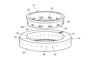
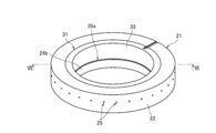
- FIG. 2A is a perspective view of the in-furnace gas supply device according to the first embodiment.
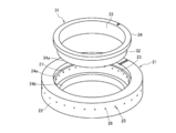
- 2B is an exploded perspective view of FIG. 2A.
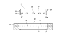
- 3A is a cross-sectional view of FIG. 2B.
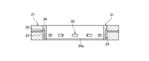
- 3B is a cross-sectional view taken along the line III-III in FIG. 2A.
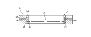
- FIG. 4 is a cross-sectional view of the in-furnace gas supply device according to the second embodiment.
- FIG. 5A is a perspective view of the in-furnace gas supply device according to the third embodiment.
- An optical fiber is made by inserting a glass base material for optical fiber (hereinafter referred to as a glass base material) mainly composed of quartz into a core tube of an optical fiber drawing furnace (hereinafter referred to as a drawing furnace).
- a glass base material mainly composed of quartz
- the tip is heated and melted to reduce the diameter so that the wire is drawn from below the drawing furnace. Since the temperature in the drawing furnace at this time is as high as about 2000 ° C., carbon having excellent heat resistance is used for the parts in the drawing furnace.
- Patent Documents 1 to 3 disclose structures in which outside air is not involved in the drawing furnace.
- the gas introduced into the drawing furnace is uniformly supplied into the drawing furnace in the circumferential direction.
- the gas flow rate is large near the center of the gas outlet and decreases as it moves away from the periphery.
- the flow velocity is uneven.
- the gas temperature is low (without heating)
- the temperature difference between the temperature of the gas introduction part and the temperature of the drawing furnace center reaching the glass melting point is large. Therefore, temperature unevenness occurs in the drawing furnace.
- the flow velocity unevenness or the temperature unevenness occurs, gas convection easily occurs in the drawing furnace, and the outer diameter fluctuation of the drawn optical fiber increases.
- an object of the present invention to provide an in-furnace gas supply device, an optical fiber manufacturing device, and an optical fiber manufacturing method that are less likely to cause gas flow velocity unevenness and temperature non-uniformity and can reduce fluctuations in the outer diameter of the optical fiber.
- An in-furnace gas supply apparatus is (1) an in-furnace gas supply apparatus that supplies gas into a drawing furnace, the gas being introduced from a predetermined first gas inlet, A first flow path that flows from the first gas outlet toward the gas storage section, and a gas stored in the gas storage section is introduced from a predetermined second gas inlet, and from the predetermined second gas outlet to the drawing furnace A second flow path that flows toward the core tube, and the gas storage portion is provided between the first gas outlet and the second gas inlet, and an opening position of the second gas inlet However, it is provided at a position different from the opening position of the first gas outlet.
- the second gas inlet of the second flow path is provided at a position that does not face the first gas outlet of the first flow path, and the gas emitted from the first gas outlet collides with the periphery of the second gas inlet. Since the flow rate is lowered, it is difficult for the gas flow rate unevenness when entering the drawing furnace to occur. In addition, by providing a gas reservoir between the first gas outlet and the second gas inlet, it takes time until the gas exiting from the first gas outlet enters the second gas inlet, and the heat in the drawing furnace is increased. Since the temperature rises due to heating, the temperature unevenness of the gas in the drawing furnace hardly occurs.
- the outer member having the first flow path, and the inner member having the second flow path are disposed on the inner side of the outer member. With. If it divides
- the second gas outlet is formed by a plurality of long holes or slits along the circumferential direction of the furnace core tube.
- the second gas outlet is formed with a plurality of elongated holes or slits, the flow rate of the gas from the second flow path can be reduced and the flow rate unevenness can be reduced as compared with the case where the second gas outlet is formed with a round hole.
- the second gas outlet is formed by a single continuous slit extending over the entire circumference of the furnace core tube. If the second gas outlet is formed by a continuous slit, the flow rate of the gas from the second flow path can be further reduced, and the flow rate unevenness can be further reduced.
- An optical fiber manufacturing apparatus includes the above-described in-furnace gas supply apparatus and a drawing furnace into which a glass preform for optical fiber is inserted. It is possible to provide an optical fiber manufacturing apparatus in which variations in flow velocity and temperature are less likely to occur and fluctuations in the outer diameter of the optical fiber are small.
- a method of manufacturing an optical fiber according to an aspect of the present disclosure uses the above-described furnace gas supply device, inserts a glass preform for an optical fiber into the drawing furnace filled with the gas, A fiber glass preform is heated and melted in the drawing furnace to draw an optical fiber. It is possible to provide an optical fiber manufacturing method in which variations in flow velocity and temperature are less likely to occur, and fluctuations in the outer diameter of the optical fiber are small.
- FIG. 1 is a diagram illustrating an outline of an optical fiber drawing furnace according to an embodiment of the present disclosure.
- the drawing furnace 1 includes a furnace casing 2, a furnace core tube 3, a heating source (heater) 4, a seal structure 10, and an in-furnace gas supply device 20.
- the furnace housing 2 has an upper end opening 2a and a lower end opening 2b, and is made of, for example, stainless steel.
- the core tube 3 is formed in a cylindrical shape at the center of the furnace housing 2 and communicates with the upper end opening 2a.
- the core tube 3 is made of carbon, and the glass base material 5 is inserted into the core tube 3 while being sealed by the seal structure 10 from the upper end opening 2a.
- a heater 4 is disposed so as to surround the furnace core tube 3, and a heat insulating material 7 is accommodated so as to cover the outside of the heater 4.
- the heater 4 heats and melts the glass base material 5 inserted into the core tube 3, and hangs down the optical fiber 5b melted and reduced in diameter from the lower end portion 5a.
- the glass base material 5 can be moved in a drawing direction (downward direction) by a separately provided moving mechanism, and a support bar 6 for hanging and supporting the glass base material 5 on the upper side of the glass base material 5. Are connected.
- the in-furnace gas supply device 20 is provided, for example, between the seal structure 10 and the upper end opening 2a, and contains an inert gas (for example, argon or nitrogen) in the furnace core tube 3 for preventing oxidation and deterioration. Gas) to be supplied.
- an inert gas for example, argon or nitrogen
- the example is not restricted to this.
- an upper lid that is an upper end opening narrower than the inner diameter d of the core tube 3 may be provided on the upper side of the core tube 3, and in this case, the gap to be sealed is the narrow upper end opening and the glass base material 5. It becomes a gap generated between the two.
- the cross-sectional shape of the glass base material 5 is basically generated to aim at a perfect circle, but some non-circles may exist regardless of the accuracy, and the glass base material 5 may have an elliptical shape. May be.
- Example 1 is a perspective view of the in-furnace gas supply device of the first embodiment, and FIG. 2B is an exploded perspective view of FIG. 2A.
- 3A is a cross-sectional view of FIG. 2B, and FIG. 3B is a cross-sectional view taken along line III-III of FIG. 2A.
- the in-furnace gas supply device 20 includes an outer member 21 and an inner member 31 that are formed in a cylindrical shape.
- the inner member 31 is disposed on the inner side of the outer member 21 and is detachable from the outer member 21.
- the outer member 21 is made of carbon, for example, and has a concentric outer peripheral wall 22 and inner peripheral wall 23 as shown in FIG. 2B. 3A, for example, the lower end of the inner peripheral wall 23 extends toward the radially inner side of the outer member 21, and a pedestal portion 24 on which the inner member 31 can be placed is formed.
- the outer member 21 has a first flow path 25 therein. Specifically, the first flow path 25 extends in the radial direction of the outer member 21 and is formed through the outer peripheral wall 22 and the inner peripheral wall 23.
- the first flow path 25 is formed by, for example, a round hole, and as shown in FIG. 2B, the first gas inlet 26 opens to the outer peripheral wall 22, and the first gas outlet 27 opens to the inner peripheral wall 23.
- the first gas inlet 26 corresponds to the first gas inlet of the first flow path of the present disclosure
- the first gas outlet 27 corresponds to the first gas outlet of the first flow path of the present disclosure.
- 20 to 30 first flow paths 25 are provided in the outer member 21, and are arranged at substantially equal intervals along the circumferential direction of the outer member 21. Note that the amount of gas supplied toward the first flow path 25 is preferably controlled by a controller (not shown).
- the inner member 31 is made of carbon, for example, and has a concentric outer peripheral wall 32 and inner peripheral wall 33 as shown in FIG. 2B. Further, as shown in FIG. 3A, for example, a flange 34 extending toward the radially outer side of the inner member 31 is formed at the upper end of the inner peripheral wall 33.
- the inner member 31 has a second flow path 35 therein. Specifically, the second flow path 35 extends in the radial direction of the inner member 31 and is formed through the outer peripheral wall 32 and the inner peripheral wall 33.
- the second flow path 35 is formed by, for example, a long hole having a round hole extending along the circumferential direction of the inner member 31, the second gas inlet 36 opens to the outer peripheral wall 32, and the second gas outlet 37 is the inner peripheral wall 33. Is open.
- the second gas inlet 36 corresponds to the second gas inlet of the second flow path of the present disclosure
- the second gas outlet 37 corresponds to the second gas outlet of the second flow path of the present disclosure.
- twelve second flow paths 35 are provided in the inner member 31, and are arranged at substantially equal intervals along the circumferential direction of the inner member 31. 2A, FIG. 2B, FIG. 3A, and FIG. 3B have been described with an example in which a long hole is formed from the second gas inlet 36 to the second gas outlet 37, the second gas inlet 36 is a round hole.
- the second gas outlet 37 may be formed in a long hole.
- the second flow path 35 is formed at a position that does not face the first flow path 25.
- the second flow path 35 is in the height direction of the drawing furnace (the same direction as the height direction of the outer member 21 and the inner member 31: the vertical direction in FIGS. 2A, 2B, 3A, and 3B).
- the second gas inlet 36 does not face the first gas outlet 27 but is opposed to the inner peripheral wall 23 below the first gas outlet 27. ing. That is, the first gas outlet 27 is also disposed opposite to the outer peripheral wall 32 above the second gas inlet 36.
- a buffer space 40 is provided between the outer member 21 and the inner member 31.
- the buffer space 40 corresponds to the gas storage unit of the present disclosure. Specifically, when the inner member 31 shown in FIG. 3A is lowered toward the outer member 21 and the lower end portion 34a of the inner member 31 is placed on the pedestal portion 24 of the outer member 21, the outer member 21 is shown in FIG. 3B.
- An annular buffer space 40 is formed between the inner peripheral wall 23 of the inner member 31 and the outer peripheral wall 32 of the inner member 31, and between the flange portion 34 of the inner member 31 and the pedestal portion 24 of the outer member 21.
- the buffer space 40 can store the gas that has exited from the first gas outlet 27 described with reference to FIG. 3A and has not yet entered the second gas inlet 36.
- the second gas inlet 36 is provided at a position not facing the first gas outlet 27, and the gas emitted from the first gas outlet 27 collides with the outer peripheral wall 32 of the inner member 31 and has a flow velocity. Since it decreases, it becomes difficult for unevenness in the flow rate of the gas when entering the drawing furnace to occur, and the flow rate of the gas entering the drawing furnace is equalized.
- the buffer space 40 between the first gas outlet 27 and the second gas inlet 36 it takes time until the gas exiting the first gas outlet 27 enters the second gas inlet 36, and the drawing is performed. Since the temperature rises due to heating with the heat in the furnace, the temperature unevenness of the gas hardly occurs, and the temperature of the gas in the drawing furnace is equalized.
- the first flow path 25 and the second flow path 35 can be easily formed, and the buffer space 40 can be easily provided. Furthermore, if the gas outlet 37 of the second flow path 35 is formed with a plurality of elongated holes, the flow rate of the gas from the second flow path 35 can be reduced as compared with the case where it is formed with a round hole.
- FIG. 4 is a cross-sectional view of the in-furnace gas supply device according to the second embodiment.
- the second embodiment has the same configuration as the first embodiment except for the shape of the second flow path 35.
- the 2nd flow path 35 is demonstrated in detail and description of the outer side member 21 etc. is abbreviate
- the second flow path 35 is formed, for example, by a slit having a long hole extending along the circumferential direction of the inner member 31, the gas inlet 36 opens to the outer peripheral wall 32, and the gas outlet 37 Opened to the peripheral wall 33.
- six second flow paths 35 are provided in the inner member 31, and are arranged at substantially equal intervals along the circumferential direction of the inner member 31.
- the second flow path 35 is formed at a position that does not face the first flow path 25, and the second gas inlet 36 does not face the first gas outlet 27, and the outer member 21.
- the inner peripheral wall 23 is opposed to the inner peripheral wall 23.
- a buffer space 40 is provided between the outer member 21 and the inner member 31, and gas before entering the second gas inlet 36 can be stored.
- FIG. 5A is a perspective view of the in-furnace gas supply device of Example 3, and FIG. 5B is an exploded perspective view of FIG. 5A.
- 6 is a cross-sectional view taken along line VI-VI in FIG. 5A.
- the outer member 21 has, for example, an upper end of the inner peripheral wall 23 that is recessed outward in the radial direction of the outer member 21, and a grip portion that can grip the flange portion 34 of the inner member 31 from below. 24a is formed.
- the first flow path 25 is the same as in the first and second embodiments.
- a stepped portion 24 b extending toward the radially inner side of the outer member 21 is provided at the lower end of the inner peripheral wall 23 of the outer member 21.
- the inner member 31 has a second flow path 35a at its lower end. Specifically, as shown in FIG. 6, the second flow path 35 a is formed between the lower end portion 34 a of the inner member 31 and the stepped portion 24 b of the outer member 21.
- the second flow path 35 a is formed by a slit having a long hole extending along the circumferential direction of the inner member 31, extends in the radial direction of the inner member 31, and the second gas inlet 36 is formed on the outer peripheral wall 32.
- the second gas outlet 37 is opened at the lower end of the inner peripheral wall 33.
- One second flow path 35 a is provided in the inner member 31, and is formed continuously along the circumferential direction of the inner member 31.
- the second flow path 35 a is formed at a position not facing the first flow path 25, and the second gas inlet 36 of the second flow path 35 a is the first gas of the first flow path 25. It is not opposed to the outlet 27 but is disposed opposite to the inner peripheral wall 23 below the first gas outlet 27 shown in FIG. 5B. As shown in FIG. 6, a buffer space 40 is provided between the outer member 21 and the inner member 31, and gas before entering the second gas inlet 36 can be stored.
- the present disclosure is not limited to this example, and the outer member and the inner member can be integrally formed.
- the in-furnace gas supply device 20 is not limited to the example installed between the seal structure 10 and the upper end opening 2a.
- the present invention can also be applied when installed in a furnace core tube.
- SYMBOLS 1 Optical fiber drawing furnace, 2 ... Furnace housing, 2a ... Upper end opening part, 2b ... Lower end opening part, 3 ... Furnace core tube, 4 ... Heater, 5 ... Optical fiber glass preform, 5a ... Lower end part, 5b ... Optical fiber, 6 ... Support rod, 7 ... Heat insulating material, 10 ... Seal structure, 20 ... Gas supply device in furnace, 21 ... Outer member, 22 ... Outer wall, 23 ... Inner wall, 24 ... Base part, 24a ... Gripping portion, 24b ... stepped portion, 25 ... first flow path, 26 ... first gas inlet, 27 ... first gas outlet, 31 ... inner member, 32 ... outer peripheral wall, 33 ... inner peripheral wall, 34 ... collar, 34a ... lower end, 35, 35a ... second flow path, 36 ... second gas inlet, 37 ... second gas outlet, 40 ... buffer space.
Landscapes
- Engineering & Computer Science (AREA)
- Chemical & Material Sciences (AREA)
- Life Sciences & Earth Sciences (AREA)
- General Life Sciences & Earth Sciences (AREA)
- Geochemistry & Mineralogy (AREA)
- Manufacturing & Machinery (AREA)
- Materials Engineering (AREA)
- Organic Chemistry (AREA)
- Manufacture, Treatment Of Glass Fibers (AREA)
Abstract
本発明は、ガスの流速ムラや温度ムラを生じ難くし、光ファイバの外径変動を小さくすることができる炉内ガス供給装置などを提供することを目的とする。 本発明は、線引炉内にガスを供給する炉内ガス供給装置である。ガスを所定の第1ガス入口から導入し、所定の第1ガス出口からガス貯留部に向けて流す第1流路と、ガス貯留部に溜められたガスを所定の第2ガス入口から導入し、所定の第2ガス出口から線引炉の炉心管に向けて流す第2流路と、を有する。ガス貯留部は、第1ガス出口と第2ガス入口との間に設けられている。第2ガス入口の開口位置が、第1ガス出口の開口位置とは異なる位置に設けられている。
Description
本開示は、炉内ガス供給装置、光ファイバ製造装置、光ファイバの製造方法に関する。
本出願は、2018年03月23日出願の日本出願第2018-057227号に基づく優先権を主張し、前記日本出願に記載された全ての記載内容を援用するものである。
本出願は、2018年03月23日出願の日本出願第2018-057227号に基づく優先権を主張し、前記日本出願に記載された全ての記載内容を援用するものである。
特許文献1~3には、線引炉内に外気を巻き込まない構造が開示されている。
本開示の一態様に係る炉内ガス供給装置は、線引炉内にガスを供給する炉内ガス供給装置であって、前記ガスを所定の第1ガス入口から導入し、所定の第1ガス出口からガス貯留部に向けて流す第1流路と、前記ガス貯留部に溜められたガスを所定の第2ガス入口から導入し、所定の第2ガス出口から前記線引炉の炉心管に向けて流す第2流路と、を有し、前記ガス貯留部は、前記第1ガス出口と前記第2ガス入口との間に設けられており、前記第2ガス入口の開口位置が、前記第1ガス出口の開口位置とは異なる位置に設けられている。
[本開示が解決しようとする課題]
光ファイバは、石英を主成分とする光ファイバ用ガラス母材(以下、ガラス母材という)を光ファイバ用線引炉(以下、線引炉という)の炉心管内に挿入し、ガラス母材の先端を加熱溶融して細径化することにより、線引炉の下方から線引きされる。このときの線引炉内の温度は、約2000℃と非常に高温となるので、線引炉内の部品には、耐熱性に優れたカーボンが用いられている。
光ファイバは、石英を主成分とする光ファイバ用ガラス母材(以下、ガラス母材という)を光ファイバ用線引炉(以下、線引炉という)の炉心管内に挿入し、ガラス母材の先端を加熱溶融して細径化することにより、線引炉の下方から線引きされる。このときの線引炉内の温度は、約2000℃と非常に高温となるので、線引炉内の部品には、耐熱性に優れたカーボンが用いられている。
この場合、線引炉内にガスを供給して線引炉内を陽圧にし、外気(酸素)が線引炉内に入り込むことを防いでいるが、線引炉とガラス母材との隙間でうまく気密が取れていないと(シールされていないと)、外気を線引炉内に巻き込んで線引炉の寿命に影響を与える。上記特許文献1~3には、線引炉内に外気を巻き込まない構造が開示されている。
ところで、線引炉内に導入されるガスは、線引炉内に周方向均等に供給されることが望ましい。ガスを一定の面積を持つガス出口から線引炉内に送り込む場合、ガスの流速は、ガス出口の中心部付近では大きく、周辺部へ離れるに連れて小さくなるので、線引炉内では周方向に流速ムラが生ずる。また、ガスの温度が低い状態で(加熱せずに)線引炉内に送り込む場合、ガス導入部の温度と、ガラス融点程度にまで到達する線引炉中心部の温度との温度差が大きくなるため、線引炉内では温度ムラが生ずる。流速ムラや温度ムラが生ずると、線引炉内でガスの対流が生じやすくなり、線引きした光ファイバの外径変動が大きくなる。
そこで、ガスの流速ムラや温度ムラを生じ難くし、光ファイバの外径変動を小さくすることができる炉内ガス供給装置、光ファイバ製造装置、光ファイバの製造方法を提供することを目的とする。
[本開示の効果]
本開示によれば、線引炉内でガスの流速ムラや温度ムラが生じ難くなり、光ファイバの外径変動を小さくすることができる。
本開示によれば、線引炉内でガスの流速ムラや温度ムラが生じ難くなり、光ファイバの外径変動を小さくすることができる。
[本開示の実施形態の説明]
最初に本開示の実施形態の内容を列記して説明する。
本開示の一態様に係る炉内ガス供給装置は、(1)線引炉内にガスを供給する炉内ガス供給装置であって、前記ガスを所定の第1ガス入口から導入し、所定の第1ガス出口からガス貯留部に向けて流す第1流路と、前記ガス貯留部に溜められたガスを所定の第2ガス入口から導入し、所定の第2ガス出口から前記線引炉の炉心管に向けて流す第2流路と、を有し、前記ガス貯留部は、前記第1ガス出口と前記第2ガス入口との間に設けられており、前記第2ガス入口の開口位置が、前記第1ガス出口の開口位置とは異なる位置に設けられている。第2流路の第2ガス入口が、第1流路の第1ガス出口に対向しない位置に設けられており、第1ガス出口から出たガスは、第2ガス入口の周囲に衝突して流速が低下するので、線引炉内に入る際のガスの流速ムラが生じ難くなる。また、第1ガス出口と第2ガス入口との間にガス貯留部を設けることにより、第1ガス出口から出たガスが第2ガス入口に入るまでに時間がかかり、線引炉内の熱で加熱されて温度が上昇するので、線引炉内でのガスの温度ムラが生じ難くなる。
最初に本開示の実施形態の内容を列記して説明する。
本開示の一態様に係る炉内ガス供給装置は、(1)線引炉内にガスを供給する炉内ガス供給装置であって、前記ガスを所定の第1ガス入口から導入し、所定の第1ガス出口からガス貯留部に向けて流す第1流路と、前記ガス貯留部に溜められたガスを所定の第2ガス入口から導入し、所定の第2ガス出口から前記線引炉の炉心管に向けて流す第2流路と、を有し、前記ガス貯留部は、前記第1ガス出口と前記第2ガス入口との間に設けられており、前記第2ガス入口の開口位置が、前記第1ガス出口の開口位置とは異なる位置に設けられている。第2流路の第2ガス入口が、第1流路の第1ガス出口に対向しない位置に設けられており、第1ガス出口から出たガスは、第2ガス入口の周囲に衝突して流速が低下するので、線引炉内に入る際のガスの流速ムラが生じ難くなる。また、第1ガス出口と第2ガス入口との間にガス貯留部を設けることにより、第1ガス出口から出たガスが第2ガス入口に入るまでに時間がかかり、線引炉内の熱で加熱されて温度が上昇するので、線引炉内でのガスの温度ムラが生じ難くなる。
(2)本開示の炉内ガス供給装置の一態様では、前記第1流路を有した外側部材と、該外側部材よりも内側に配置されるとともに、前記第2流路を有した内側部材とを備える。外側部材と内側部材とに分割すれば、第1流路や第2流路を形成しやすくなり、さらに、ガス貯留部を設けやすい。
(3)本開示の炉内ガス供給装置の一態様では、前記第2ガス出口が、前記炉心管の周方向に沿った複数個の長穴またはスリットで形成されている。第2ガス出口を複数個の長穴またはスリットで形成すれば、丸穴で形成した場合に比べて第2流路からのガスの流速を小さくでき、流速ムラを小さくできる。
(4)本開示の炉内ガス供給装置の一態様では、前記第2ガス出口が、前記炉心管の全周に亘る連続した1個のスリットで形成されている。第2ガス出口を連続したスリットで形成すれば、第2流路からのガスの流速をさらに小さくでき、流速ムラをさらに小さくできる。
(3)本開示の炉内ガス供給装置の一態様では、前記第2ガス出口が、前記炉心管の周方向に沿った複数個の長穴またはスリットで形成されている。第2ガス出口を複数個の長穴またはスリットで形成すれば、丸穴で形成した場合に比べて第2流路からのガスの流速を小さくでき、流速ムラを小さくできる。
(4)本開示の炉内ガス供給装置の一態様では、前記第2ガス出口が、前記炉心管の全周に亘る連続した1個のスリットで形成されている。第2ガス出口を連続したスリットで形成すれば、第2流路からのガスの流速をさらに小さくでき、流速ムラをさらに小さくできる。
(5)本開示の一態様に係る光ファイバ製造装置は、上記の炉内ガス供給装置と、光ファイバ用ガラス母材が挿入される線引炉と、からなる。流速ムラ、温度ムラが生じ難くなり、光ファイバの外径変動の少ない光ファイバ製造装置を提供することができる。
(6)本開示の一態様に係る光ファイバの製造方法は、上記の炉内ガス供給装置を用い、前記ガスで満たした前記線引炉内に光ファイバ用ガラス母材を挿入し、該光ファイバ用ガラス母材を前記線引炉内で加熱溶融して光ファイバを線引きする。流速ムラ、温度ムラが生じ難くなり、光ファイバの外径変動の少ない光ファイバ製造方法を提供することができる。
(6)本開示の一態様に係る光ファイバの製造方法は、上記の炉内ガス供給装置を用い、前記ガスで満たした前記線引炉内に光ファイバ用ガラス母材を挿入し、該光ファイバ用ガラス母材を前記線引炉内で加熱溶融して光ファイバを線引きする。流速ムラ、温度ムラが生じ難くなり、光ファイバの外径変動の少ない光ファイバ製造方法を提供することができる。
[本開示の実施形態の詳細]
以下、添付図面を参照しながら、本開示による炉内ガス供給装置、光ファイバ製造装置、光ファイバの製造方法の好適な実施の形態について説明する。なお、以下ではヒータにより炉心管を加熱する抵抗炉を例に説明するが、コイルに高周波電源を印加し、炉心管を誘導加熱する誘導炉にも、本開示は適用可能である。また、ガラス母材の吊り下げ機構や、線引炉の構成なども、下記で説明するのは一例であり、これに限定されるものではない。
以下、添付図面を参照しながら、本開示による炉内ガス供給装置、光ファイバ製造装置、光ファイバの製造方法の好適な実施の形態について説明する。なお、以下ではヒータにより炉心管を加熱する抵抗炉を例に説明するが、コイルに高周波電源を印加し、炉心管を誘導加熱する誘導炉にも、本開示は適用可能である。また、ガラス母材の吊り下げ機構や、線引炉の構成なども、下記で説明するのは一例であり、これに限定されるものではない。
図1は、本開示の一実施形態による光ファイバ用線引炉の概略を説明する図である。
線引炉1は、炉筐体2と、炉心管3と、加熱源(ヒータ)4と、シール構造10と、炉内ガス供給装置20とを備えている。炉筐体2は、上端開口部2aと下端開口部2bを有し、例えば、ステンレス鋼製で形成されている。炉心管3は、炉筐体2の中央部に円筒状で形成され、上端開口部2aと連通している。炉心管3はカーボン製であり、この炉心管3内には、ガラス母材5が上端開口部2aからシール構造10でシールされた状態で挿入される。
線引炉1は、炉筐体2と、炉心管3と、加熱源(ヒータ)4と、シール構造10と、炉内ガス供給装置20とを備えている。炉筐体2は、上端開口部2aと下端開口部2bを有し、例えば、ステンレス鋼製で形成されている。炉心管3は、炉筐体2の中央部に円筒状で形成され、上端開口部2aと連通している。炉心管3はカーボン製であり、この炉心管3内には、ガラス母材5が上端開口部2aからシール構造10でシールされた状態で挿入される。
炉筐体2内には、ヒータ4が炉心管3を囲むように配置され、断熱材7がヒータ4の外側を覆うように収納されている。ヒータ4は、炉心管3の内部に挿入されたガラス母材5を加熱溶融し、その下端部5aから溶融縮径された光ファイバ5bを垂下させる。ガラス母材5は、別途設けた移動機構により線引方向(下側方向)に移動可能であり、ガラス母材5の上側には、ガラス母材5を吊り下げて支持するための支持棒6が連結されている。また、炉内ガス供給装置20は、例えばシール構造10と上端開口部2aとの間に設けられ、炉心管3内に、酸化や劣化防止のための不活性ガス(例えばアルゴンまたは窒素等を含有するガス)を供給可能に形成されている。
なお、図1では、炉心管3の内壁の上端部がそのまま上端開口部2aを形成している例を挙げているが、これに限ったものではない。例えば、炉心管3の内径dよりさらに狭い上端開口部となる上蓋を炉心管3の上側に設けてもよく、この場合にシール対象となる隙間は、この狭い上端開口部とガラス母材5との間に生じる隙間となる。また、ガラス母材5の断面形状は、基本的に真円を目指して生成されたものとするが、その精度を問わず一部で非円が存在してもよく、また楕円形などであってもよい。
(実施例1)
図2Aは実施例1の炉内ガス供給装置の斜視図であり、図2Bは図2Aの分解斜視図である。また、図3Aは図2Bの断面図であり、図3Bは図2AのIII-III線矢視断面図である。
図2Aに示すように、炉内ガス供給装置20は、円筒形状に形成された外側部材21および内側部材31を有する。内側部材31は、外側部材21よりも内側に配置されており、外側部材21に対して着脱可能である。
図2Aは実施例1の炉内ガス供給装置の斜視図であり、図2Bは図2Aの分解斜視図である。また、図3Aは図2Bの断面図であり、図3Bは図2AのIII-III線矢視断面図である。
図2Aに示すように、炉内ガス供給装置20は、円筒形状に形成された外側部材21および内側部材31を有する。内側部材31は、外側部材21よりも内側に配置されており、外側部材21に対して着脱可能である。
外側部材21は、例えばカーボンで形成され、図2Bに示すように、同心の外周壁22と内周壁23を有する。また、図3Aに示すように、例えば、内周壁23の下端は、外側部材21の径方向内側に向けて延びており、内側部材31を載置可能な台座部24が形成されている。
外側部材21は、その内部に第1流路25を有する。詳しくは、第1流路25は、外側部材21の径方向に延びて外周壁22と内周壁23とを貫通して形成されている。
外側部材21は、その内部に第1流路25を有する。詳しくは、第1流路25は、外側部材21の径方向に延びて外周壁22と内周壁23とを貫通して形成されている。
第1流路25は、例えば丸穴で形成され、図2Bに示すように、第1ガス入口26が外周壁22に開口し、第1ガス出口27が内周壁23に開口している。なお、第1ガス入口26が本開示の第1流路の第1ガス入口に相当し、第1ガス出口27が本開示の第1流路の第1ガス出口に相当する。また、第1流路25は、外側部材21に例えば20~30個設けられており、外側部材21の周方向に沿って略等間隔に配置されている。
なお、第1流路25に向かうガスの供給量は、コントローラ(図示省略)で制御されることが好ましい。
なお、第1流路25に向かうガスの供給量は、コントローラ(図示省略)で制御されることが好ましい。
内側部材31は、例えばカーボン製で形成され、図2Bに示すように、同心の外周壁32と内周壁33を有する。また、図3Aに示すように、例えば、内周壁33の上端には、内側部材31の径方向外側に向けて延びた鍔部34が形成されている。
内側部材31は、その内部に第2流路35を有する。詳しくは、第2流路35は、内側部材31の径方向に延びて外周壁32と内周壁33とを貫通して形成されている。
内側部材31は、その内部に第2流路35を有する。詳しくは、第2流路35は、内側部材31の径方向に延びて外周壁32と内周壁33とを貫通して形成されている。
第2流路35は、例えば丸穴を内側部材31の周方向に沿って伸ばした長穴で形成され、第2ガス入口36が外周壁32に開口し、第2ガス出口37が内周壁33に開口している。なお、第2ガス入口36が本開示の第2流路の第2ガス入口に相当し、第2ガス出口37が本開示の第2流路の第2ガス出口に相当する。また、第2流路35は、内側部材31に例えば12個設けられており、内側部材31の周方向に沿って略等間隔に配置されている。なお、図2A,図2B,図3A,図3Bでは、第2ガス入口36から第2ガス出口37に亘って長穴に形成した例を挙げて説明したが、第2ガス入口36は丸穴で形成し、第2ガス出口37を長穴に形成してもよい。
ただし、第2流路35は、第1流路25に対向しない位置に形成される。具体的には、第2流路35は、線引炉の高さ方向(外側部材21や内側部材31の高さ方向と同じ方向:図2A,図2B,図3A,図3Bの上下方向)で見て第1流路25よりも下方に形成されており、第2ガス入口36は、第1ガス出口27に対向せず、第1ガス出口27よりも下方の内周壁23に対向配置されている。つまり、第1ガス出口27も、第2ガス入口36よりも上方の外周壁32に対向配置されている。なお、内側部材31の上面や外側部材21の上面には、流路の位置合わせをするためのマークを付してもよい。なお、第2ガス入口36と、第1ガス出口27とは、上下方向では無く、左右方向に位置がずれていてもよい。
また、図3Bに示すように、外側部材21と内側部材31との間には、バッファ空間40が設けられている。なお、バッファ空間40が本開示のガス貯留部に相当する。
詳しくは、図3Aに示した内側部材31を外側部材21に向けて降ろし、内側部材31の下端部34aを外側部材21の台座部24に載置すると、図3Bに示すように、外側部材21の内周壁23と内側部材31の外周壁32との間であって、内側部材31の鍔部34と外側部材21の台座部24との間に、輪状のバッファ空間40が形成される。バッファ空間40には、図3Aで説明した第1ガス出口27から出て、第2ガス入口36に入る前のガスを貯留できる。
詳しくは、図3Aに示した内側部材31を外側部材21に向けて降ろし、内側部材31の下端部34aを外側部材21の台座部24に載置すると、図3Bに示すように、外側部材21の内周壁23と内側部材31の外周壁32との間であって、内側部材31の鍔部34と外側部材21の台座部24との間に、輪状のバッファ空間40が形成される。バッファ空間40には、図3Aで説明した第1ガス出口27から出て、第2ガス入口36に入る前のガスを貯留できる。
このように、第2ガス入口36が、第1ガス出口27に対向しない位置に設けられており、第1ガス出口27から出たガスは、内側部材31の外周壁32に衝突して流速が低下するので、線引炉内に入る際のガスの周方向の流速ムラが生じ難くなり、線引炉内に入るガスの流速が均等化される。
また、第1ガス出口27と第2ガス入口36との間にバッファ空間40を設けることにより、第1ガス出口27から出たガスが第2ガス入口36に入るまでに時間がかかり、線引炉内の熱で加熱されて温度が上昇するので、ガスの温度ムラが生じ難くなり、線引炉内のガスの温度が均等化される。
また、外側部材21と内側部材31とに分割すれば、第1流路25や第2流路35を形成しやすくなり、さらに、バッファ空間40も設けやすくなる。
さらに、第2流路35のガス出口37を複数個の長穴で形成すれば、丸穴で形成した場合に比べて第2流路35からのガスの流速を小さくできる。
さらに、第2流路35のガス出口37を複数個の長穴で形成すれば、丸穴で形成した場合に比べて第2流路35からのガスの流速を小さくできる。
(実施例2)
図4は、実施例2の炉内ガス供給装置の断面図である。実施例2は、第2流路35の形状を除き、実施例1と同じ構成である。このため、第2流路35について詳細に説明し、外側部材21などの説明は省略する。
図4に示すように、第2流路35は、例えば長穴を内側部材31の周方向に沿って伸ばしたスリットで形成され、ガス入口36が外周壁32に開口し、ガス出口37が内周壁33に開口している。また、第2流路35は、内側部材31に例えば6個設けられており、内側部材31の周方向に沿って略等間隔に配置されている。
図4は、実施例2の炉内ガス供給装置の断面図である。実施例2は、第2流路35の形状を除き、実施例1と同じ構成である。このため、第2流路35について詳細に説明し、外側部材21などの説明は省略する。
図4に示すように、第2流路35は、例えば長穴を内側部材31の周方向に沿って伸ばしたスリットで形成され、ガス入口36が外周壁32に開口し、ガス出口37が内周壁33に開口している。また、第2流路35は、内側部材31に例えば6個設けられており、内側部材31の周方向に沿って略等間隔に配置されている。
実施例2の場合にも、第2流路35は、第1流路25に対向しない位置に形成され、第2ガス入口36は、第1ガス出口27に対向しておらず、外側部材21の内周壁23に対向配置されている。
また、外側部材21と内側部材31との間には、バッファ空間40が設けられており、第2ガス入口36に入る前のガスを貯留できる。
また、外側部材21と内側部材31との間には、バッファ空間40が設けられており、第2ガス入口36に入る前のガスを貯留できる。
(実施例3)
図5Aは実施例3の炉内ガス供給装置の斜視図であり、図5Bは図5Aの分解斜視図である。また、図6は図5AのVI-VI線矢視断面図である。
外側部材21は、図5Bに示すように、例えば、内周壁23の上端が、外側部材21の径方向外側に向けて窪んでおり、内側部材31の鍔部34を下方から把持可能な把持部24aが形成されている。なお、第1流路25は実施例1,2と同じである。
図5Aは実施例3の炉内ガス供給装置の斜視図であり、図5Bは図5Aの分解斜視図である。また、図6は図5AのVI-VI線矢視断面図である。
外側部材21は、図5Bに示すように、例えば、内周壁23の上端が、外側部材21の径方向外側に向けて窪んでおり、内側部材31の鍔部34を下方から把持可能な把持部24aが形成されている。なお、第1流路25は実施例1,2と同じである。
また、外側部材21の内周壁23の下端には、外側部材21の径方向内側に向けて延びた段付き部24bが設けられている。
内側部材31は、その下端に第2流路35aを有する。詳しくは、第2流路35aは、図6に示すように、内側部材31の下端部34aと外側部材21の段付き部24bとの間に形成されている。
内側部材31は、その下端に第2流路35aを有する。詳しくは、第2流路35aは、図6に示すように、内側部材31の下端部34aと外側部材21の段付き部24bとの間に形成されている。
したがって、第2流路35aは、長穴を内側部材31の周方向に沿って伸ばしたスリットで形成されることとなり、内側部材31の径方向に延び、第2ガス入口36が外周壁32の下端に開口し、第2ガス出口37が内周壁33の下端に開口している。また、第2流路35aは、内側部材31に1個設けられることとなり、内側部材31の周方向に沿って連続して形成されている。
実施例3の場合にも、第2流路35aは、第1流路25に対向しない位置に形成され、第2流路35aの第2ガス入口36は、第1流路25の第1ガス出口27に対向せず、図5Bに示した第1ガス出口27よりも下方の内周壁23に対向配置されている。
また、図6に示すように、外側部材21と内側部材31との間には、バッファ空間40が設けられ、第2ガス入口36に入る前のガスを貯留できる。
また、図6に示すように、外側部材21と内側部材31との間には、バッファ空間40が設けられ、第2ガス入口36に入る前のガスを貯留できる。
なお、実施例1~3では、外側部材21と内側部材31に分割可能な例を挙げたが、本開示はこの例に限定されず、外側部材と内側部材を一体形成することも可能である。
また、炉内ガス供給装置20は、シール構造10と上端開口部2aとの間に設置する例に限定されない。例えば、炉心管内に設置する場合にも適用できる。
また、炉内ガス供給装置20は、シール構造10と上端開口部2aとの間に設置する例に限定されない。例えば、炉心管内に設置する場合にも適用できる。
今回開示された実施の形態はすべての点で例示であって制限的なものではないと考えられるべきである。本開示の範囲は、上記した意味ではなく、請求の範囲によって示され、請求の範囲と均等の意味および範囲内でのすべての変更が含まれることが意図される。
1…光ファイバ用線引炉、2…炉筐体、2a…上端開口部、2b…下端開口部、3…炉心管、4…ヒータ、5…光ファイバ用ガラス母材、5a…下端部、5b…光ファイバ、6…支持棒、7…断熱材、10…シール構造、20…炉内ガス供給装置、21…外側部材、22…外周壁、23…内周壁、24…台座部、24a…把持部、24b…段付き部、25…第1流路、26…第1ガス入口、27…第1ガス出口、31…内側部材、32…外周壁、33…内周壁、34…鍔部、34a…下端部、35,35a…第2流路、36…第2ガス入口、37…第2ガス出口、40…バッファ空間。
Claims (6)
- 線引炉内にガスを供給する炉内ガス供給装置であって、
前記ガスを所定の第1ガス入口から導入し、所定の第1ガス出口からガス貯留部に向けて流す第1流路と、
前記ガス貯留部に溜められたガスを所定の第2ガス入口から導入し、所定の第2ガス出口から前記線引炉の炉心管に向けて流す第2流路と、を有し、
前記ガス貯留部は、前記第1ガス出口と前記第2ガス入口との間に設けられており、
前記第2ガス入口の開口位置が、前記第1ガス出口の開口位置とは異なる位置に設けられている、炉内ガス供給装置。 - 前記第1流路を有した外側部材と、該外側部材よりも内側に配置されるとともに、前記第2流路を有した内側部材とを備える、請求項1に記載の炉内ガス供給装置。
- 前記第2ガス出口が、前記炉心管の周方向に沿った複数個の長穴またはスリットで形成されている、請求項1または請求項2に記載の炉内ガス供給装置。
- 前記第2ガス出口が、前記炉心管の全周に亘る連続した1個のスリットで形成されている、請求項1または請求項2に記載の炉内ガス供給装置。
- 請求項1から請求項4のいずれか一項に記載の炉内ガス供給装置と、光ファイバ用ガラス母材が挿入される線引炉と、からなる、光ファイバ製造装置。
- 請求項1から請求項4のいずれか一項に記載の炉内ガス供給装置を用い、前記ガスで満たした前記線引炉内に光ファイバ用ガラス母材を挿入し、該光ファイバ用ガラス母材を前記線引炉内で加熱溶融して光ファイバを線引きする、光ファイバの製造方法。
Priority Applications (6)
| Application Number | Priority Date | Filing Date | Title |
|---|---|---|---|
| KR1020207027047A KR102645920B1 (ko) | 2018-03-23 | 2019-03-22 | 노내 가스 공급 장치, 광 파이버 제조 장치, 광 파이버의 제조 방법 |
| EP19771167.4A EP3770126B1 (en) | 2018-03-23 | 2019-03-22 | OVEN GAS SUPPLY DEVICE, OPTICAL FIBER PRODUCTION DEVICE, AND OPTICAL FIBER PRODUCTION METHOD |
| RU2020131122A RU2757891C1 (ru) | 2018-03-23 | 2019-03-22 | Устройство для подачи газа в печь, устройство для производства оптоволокна и способ производства оптоволокна |
| JP2020507949A JP7334724B2 (ja) | 2018-03-23 | 2019-03-22 | 炉内ガス供給装置、光ファイバ製造装置、光ファイバの製造方法 |
| CN201980021449.7A CN111902375B (zh) | 2018-03-23 | 2019-03-22 | 炉内气体供给装置、光纤制造装置、光纤的制造方法 |
| US16/981,919 US11795099B2 (en) | 2018-03-23 | 2019-03-22 | Furnace gas feeding device, optical fiber production device, and optical fiber production method |
Applications Claiming Priority (2)
| Application Number | Priority Date | Filing Date | Title |
|---|---|---|---|
| JP2018057227 | 2018-03-23 | ||
| JP2018-057227 | 2018-03-23 |
Publications (1)
| Publication Number | Publication Date |
|---|---|
| WO2019182136A1 true WO2019182136A1 (ja) | 2019-09-26 |
Family
ID=67986233
Family Applications (1)
| Application Number | Title | Priority Date | Filing Date |
|---|---|---|---|
| PCT/JP2019/012189 Ceased WO2019182136A1 (ja) | 2018-03-23 | 2019-03-22 | 炉内ガス供給装置、光ファイバ製造装置、光ファイバの製造方法 |
Country Status (7)
| Country | Link |
|---|---|
| US (1) | US11795099B2 (ja) |
| EP (1) | EP3770126B1 (ja) |
| JP (1) | JP7334724B2 (ja) |
| KR (1) | KR102645920B1 (ja) |
| CN (1) | CN111902375B (ja) |
| RU (1) | RU2757891C1 (ja) |
| WO (1) | WO2019182136A1 (ja) |
Families Citing this family (2)
| Publication number | Priority date | Publication date | Assignee | Title |
|---|---|---|---|---|
| CN112592048B (zh) * | 2020-11-25 | 2022-08-16 | 通鼎互联信息股份有限公司 | 一种光纤拉丝炉用石墨件结构 |
| CN121568910A (zh) * | 2023-07-26 | 2026-02-24 | 康宁股份有限公司 | 用于熔炉系统的反向气体注入 |
Citations (7)
| Publication number | Priority date | Publication date | Assignee | Title |
|---|---|---|---|---|
| JPS52119546U (ja) * | 1976-03-10 | 1977-09-10 | ||
| JPS62260731A (ja) | 1986-05-06 | 1987-11-13 | Sumitomo Electric Ind Ltd | 光ファイバ線引炉 |
| JPH01192741A (ja) * | 1988-01-29 | 1989-08-02 | Sumitomo Electric Ind Ltd | 光ファィバ線引き炉 |
| US20040050112A1 (en) * | 2002-08-31 | 2004-03-18 | Lg Cable Ltd. | Furnace for drawing optical fiber preform to make optical fiber and method for drawing optical fiber using the same |
| JP2007070189A (ja) | 2005-09-08 | 2007-03-22 | Shin Etsu Chem Co Ltd | 光ファイバ線引き装置及び線引き炉のシール方法 |
| JP2012056815A (ja) | 2010-09-10 | 2012-03-22 | Sumitomo Electric Ind Ltd | 線引き炉 |
| JP2018057227A (ja) | 2016-09-30 | 2018-04-05 | アイシン・エィ・ダブリュ株式会社 | インバータ装置 |
Family Cites Families (14)
| Publication number | Priority date | Publication date | Assignee | Title |
|---|---|---|---|---|
| US4101300A (en) * | 1975-11-27 | 1978-07-18 | Hitachi, Ltd. | Method and apparatus for drawing optical fiber |
| GB2212151B (en) * | 1987-11-12 | 1991-07-17 | Stc Plc | Contaminant removal in manufacture of optical fibre |
| JPH04310533A (ja) * | 1991-04-09 | 1992-11-02 | Furukawa Electric Co Ltd:The | 光ファイバの線引き方法 |
| CA2168830A1 (en) * | 1995-03-23 | 1996-09-24 | John Steele Abbott Iii | Method and apparatus for coating fibers |
| DE59602017D1 (de) * | 1996-12-17 | 1999-07-01 | Cit Alcatel | Verfahren und Vorrichtung zum Ziehen einer optischen Faser aus einer Vorform |
| JP2965037B1 (ja) * | 1998-04-03 | 1999-10-18 | 住友電気工業株式会社 | 光ファイバ線引き炉及び光ファイバ線引き方法 |
| KR100393612B1 (ko) * | 2001-01-29 | 2003-08-02 | 삼성전자주식회사 | 비접촉식으로 광섬유 편광모드분산 제어를 위한 광섬유인출 장치 |
| FI113533B (fi) | 2002-01-18 | 2004-05-14 | Photonium Oy | Kuidunvetouunin tiivistys |
| KR100812468B1 (ko) * | 2006-02-13 | 2008-03-10 | 엘에스전선 주식회사 | 오버 클래딩 장치 및 오버 클래딩 방법 |
| WO2013105302A1 (ja) * | 2012-01-10 | 2013-07-18 | 住友電気工業株式会社 | 光ファイバの製造方法および製造装置並びに光ファイバ |
| CN203212462U (zh) | 2013-05-10 | 2013-09-25 | 江苏法尔胜光子有限公司 | 一种涡流式保护气石墨拉丝炉 |
| CN204237707U (zh) * | 2014-11-14 | 2015-04-01 | 江苏南方光纤科技有限公司 | 光纤拉丝炉惰性气体净化装置 |
| US10308544B2 (en) * | 2015-10-13 | 2019-06-04 | Corning Incorporated | Gas reclamation system for optical fiber production |
| CN110272201B (zh) * | 2018-03-13 | 2023-03-10 | 康宁股份有限公司 | 用于在光纤拉制炉中回收气体的方法和设备 |
-
2019
- 2019-03-22 WO PCT/JP2019/012189 patent/WO2019182136A1/ja not_active Ceased
- 2019-03-22 JP JP2020507949A patent/JP7334724B2/ja active Active
- 2019-03-22 US US16/981,919 patent/US11795099B2/en active Active
- 2019-03-22 KR KR1020207027047A patent/KR102645920B1/ko active Active
- 2019-03-22 EP EP19771167.4A patent/EP3770126B1/en active Active
- 2019-03-22 CN CN201980021449.7A patent/CN111902375B/zh active Active
- 2019-03-22 RU RU2020131122A patent/RU2757891C1/ru active
Patent Citations (7)
| Publication number | Priority date | Publication date | Assignee | Title |
|---|---|---|---|---|
| JPS52119546U (ja) * | 1976-03-10 | 1977-09-10 | ||
| JPS62260731A (ja) | 1986-05-06 | 1987-11-13 | Sumitomo Electric Ind Ltd | 光ファイバ線引炉 |
| JPH01192741A (ja) * | 1988-01-29 | 1989-08-02 | Sumitomo Electric Ind Ltd | 光ファィバ線引き炉 |
| US20040050112A1 (en) * | 2002-08-31 | 2004-03-18 | Lg Cable Ltd. | Furnace for drawing optical fiber preform to make optical fiber and method for drawing optical fiber using the same |
| JP2007070189A (ja) | 2005-09-08 | 2007-03-22 | Shin Etsu Chem Co Ltd | 光ファイバ線引き装置及び線引き炉のシール方法 |
| JP2012056815A (ja) | 2010-09-10 | 2012-03-22 | Sumitomo Electric Ind Ltd | 線引き炉 |
| JP2018057227A (ja) | 2016-09-30 | 2018-04-05 | アイシン・エィ・ダブリュ株式会社 | インバータ装置 |
Also Published As
| Publication number | Publication date |
|---|---|
| JP7334724B2 (ja) | 2023-08-29 |
| US20210094867A1 (en) | 2021-04-01 |
| US11795099B2 (en) | 2023-10-24 |
| EP3770126A1 (en) | 2021-01-27 |
| KR102645920B1 (ko) | 2024-03-08 |
| EP3770126A4 (en) | 2021-12-15 |
| EP3770126B1 (en) | 2026-05-20 |
| RU2757891C1 (ru) | 2021-10-22 |
| CN111902375A (zh) | 2020-11-06 |
| CN111902375B (zh) | 2022-10-14 |
| JPWO2019182136A1 (ja) | 2021-03-11 |
| KR20200135357A (ko) | 2020-12-02 |
Similar Documents
| Publication | Publication Date | Title |
|---|---|---|
| CN101362628B (zh) | 用于制造光纤的设备和用于密封拉丝炉的方法 | |
| JP5880522B2 (ja) | 光ファイバ製造方法及び光ファイバ線引炉 | |
| US20030205068A1 (en) | Furnace and method for optical fiber wire driwing | |
| US20110265522A1 (en) | Optical fiber manufacturing apparatus and optical fiber manufacturing method | |
| JP7334724B2 (ja) | 炉内ガス供給装置、光ファイバ製造装置、光ファイバの製造方法 | |
| JP2015074600A (ja) | 光ファイバの製造方法 | |
| JP5556117B2 (ja) | 光ファイバ線引き方法および線引き装置 | |
| JP2018058753A (ja) | 線引き炉の封止装置 | |
| JP6973408B2 (ja) | 光ファイバ用線引炉のシール構造、光ファイバの製造方法 | |
| JP2965037B1 (ja) | 光ファイバ線引き炉及び光ファイバ線引き方法 | |
| JP2012051757A (ja) | 光ファイバ線引き方法および線引き装置 | |
| WO2015050103A1 (ja) | 光ファイバの製造方法 | |
| JP4404203B2 (ja) | 光ファイバの製造方法 | |
| JP2019026524A (ja) | 製造方法及びキャップ | |
| JP2016108192A (ja) | 光ファイバ製造方法及び光ファイバ製造装置 | |
| JP6729171B2 (ja) | 光ファイバ用線引炉のシール構造、光ファイバの製造方法 | |
| JP7476799B2 (ja) | 光ファイバ用線引炉のシール構造、光ファイバの製造方法 | |
| JP6277605B2 (ja) | 光ファイバの製造方法および製造装置 | |
| JP2004210621A (ja) | 光ファイバの線引き方法及び光ファイバの線引き装置 | |
| JPH04310533A (ja) | 光ファイバの線引き方法 | |
| JPH02199040A (ja) | 光ファイバ線引炉 | |
| JP6816670B2 (ja) | 光ファイバ用線引炉のシール構造、光ファイバの製造方法 | |
| JPH05208840A (ja) | 光ファイバ紡糸方法および光ファイバ紡糸装置 | |
| JPH06206735A (ja) | 光ファイバの線引方法 | |
| JP2012148924A (ja) | 光ファイバの線引炉及び線引き方法 |
Legal Events
| Date | Code | Title | Description |
|---|---|---|---|
| 121 | Ep: the epo has been informed by wipo that ep was designated in this application |
Ref document number: 19771167 Country of ref document: EP Kind code of ref document: A1 |
|
| ENP | Entry into the national phase |
Ref document number: 2020507949 Country of ref document: JP Kind code of ref document: A |
|
| NENP | Non-entry into the national phase |
Ref country code: DE |
|
| WWE | Wipo information: entry into national phase |
Ref document number: 2019771167 Country of ref document: EP |