WO2019184261A1 - Câble de dissipation d'énergie métallique à réinitialisation automatique - Google Patents
Câble de dissipation d'énergie métallique à réinitialisation automatique Download PDFInfo
- Publication number
- WO2019184261A1 WO2019184261A1 PCT/CN2018/105367 CN2018105367W WO2019184261A1 WO 2019184261 A1 WO2019184261 A1 WO 2019184261A1 CN 2018105367 W CN2018105367 W CN 2018105367W WO 2019184261 A1 WO2019184261 A1 WO 2019184261A1
- Authority
- WO
- WIPO (PCT)
- Prior art keywords
- rib
- self
- cable
- inverted
- resetting
- Prior art date
- Legal status (The legal status is an assumption and is not a legal conclusion. Google has not performed a legal analysis and makes no representation as to the accuracy of the status listed.)
- Ceased
Links
Images




Classifications
-
- E—FIXED CONSTRUCTIONS
- E04—BUILDING
- E04H—BUILDINGS OR LIKE STRUCTURES FOR PARTICULAR PURPOSES; SWIMMING OR SPLASH BATHS OR POOLS; MASTS; FENCING; TENTS OR CANOPIES, IN GENERAL
- E04H9/00—Buildings, groups of buildings or shelters adapted to withstand or provide protection against abnormal external influences, e.g. war-like action, earthquake or extreme climate
- E04H9/02—Buildings, groups of buildings or shelters adapted to withstand or provide protection against abnormal external influences, e.g. war-like action, earthquake or extreme climate withstanding earthquake or sinking of ground
- E04H9/021—Bearing, supporting or connecting constructions specially adapted for such buildings
- E04H9/0237—Structural braces with damping devices
-
- E—FIXED CONSTRUCTIONS
- E04—BUILDING
- E04H—BUILDINGS OR LIKE STRUCTURES FOR PARTICULAR PURPOSES; SWIMMING OR SPLASH BATHS OR POOLS; MASTS; FENCING; TENTS OR CANOPIES, IN GENERAL
- E04H9/00—Buildings, groups of buildings or shelters adapted to withstand or provide protection against abnormal external influences, e.g. war-like action, earthquake or extreme climate
- E04H9/02—Buildings, groups of buildings or shelters adapted to withstand or provide protection against abnormal external influences, e.g. war-like action, earthquake or extreme climate withstanding earthquake or sinking of ground
- E04H9/027—Preventive constructional measures against earthquake damage in existing buildings
-
- E—FIXED CONSTRUCTIONS
- E04—BUILDING
- E04H—BUILDINGS OR LIKE STRUCTURES FOR PARTICULAR PURPOSES; SWIMMING OR SPLASH BATHS OR POOLS; MASTS; FENCING; TENTS OR CANOPIES, IN GENERAL
- E04H9/00—Buildings, groups of buildings or shelters adapted to withstand or provide protection against abnormal external influences, e.g. war-like action, earthquake or extreme climate
- E04H9/02—Buildings, groups of buildings or shelters adapted to withstand or provide protection against abnormal external influences, e.g. war-like action, earthquake or extreme climate withstanding earthquake or sinking of ground
- E04H9/021—Bearing, supporting or connecting constructions specially adapted for such buildings
-
- E—FIXED CONSTRUCTIONS
- E04—BUILDING
- E04B—GENERAL BUILDING CONSTRUCTIONS; WALLS, e.g. PARTITIONS; ROOFS; FLOORS; CEILINGS; INSULATION OR OTHER PROTECTION OF BUILDINGS
- E04B1/00—Constructions in general; Structures which are not restricted either to walls, e.g. partitions, or floors or ceilings or roofs
- E04B1/62—Insulation or other protection; Elements or use of specified material therefor
- E04B1/92—Protection against other undesired influences or dangers
- E04B1/98—Protection against other undesired influences or dangers against vibrations or shocks; against mechanical destruction, e.g. by air-raids
-
- E—FIXED CONSTRUCTIONS
- E04—BUILDING
- E04H—BUILDINGS OR LIKE STRUCTURES FOR PARTICULAR PURPOSES; SWIMMING OR SPLASH BATHS OR POOLS; MASTS; FENCING; TENTS OR CANOPIES, IN GENERAL
- E04H9/00—Buildings, groups of buildings or shelters adapted to withstand or provide protection against abnormal external influences, e.g. war-like action, earthquake or extreme climate
-
- E—FIXED CONSTRUCTIONS
- E04—BUILDING
- E04H—BUILDINGS OR LIKE STRUCTURES FOR PARTICULAR PURPOSES; SWIMMING OR SPLASH BATHS OR POOLS; MASTS; FENCING; TENTS OR CANOPIES, IN GENERAL
- E04H9/00—Buildings, groups of buildings or shelters adapted to withstand or provide protection against abnormal external influences, e.g. war-like action, earthquake or extreme climate
- E04H9/02—Buildings, groups of buildings or shelters adapted to withstand or provide protection against abnormal external influences, e.g. war-like action, earthquake or extreme climate withstanding earthquake or sinking of ground
- E04H9/021—Bearing, supporting or connecting constructions specially adapted for such buildings
- E04H9/0235—Anti-seismic devices with hydraulic or pneumatic damping
-
- E—FIXED CONSTRUCTIONS
- E04—BUILDING
- E04H—BUILDINGS OR LIKE STRUCTURES FOR PARTICULAR PURPOSES; SWIMMING OR SPLASH BATHS OR POOLS; MASTS; FENCING; TENTS OR CANOPIES, IN GENERAL
- E04H9/00—Buildings, groups of buildings or shelters adapted to withstand or provide protection against abnormal external influences, e.g. war-like action, earthquake or extreme climate
- E04H9/02—Buildings, groups of buildings or shelters adapted to withstand or provide protection against abnormal external influences, e.g. war-like action, earthquake or extreme climate withstanding earthquake or sinking of ground
- E04H9/024—Structures with steel columns and beams
Definitions
- the invention relates to a self-resetting metal energy-consuming cable technology, and belongs to the field of seismic reinforcement of civil engineering.
- the support is often placed in the structure to improve the lateral stiffness of the structure and dissipate the seismic input energy.
- Existing conventional supports produce irreparable residual deformation under strong earthquakes and have various adverse effects on the structure.
- the self-reset energy-consuming support came into being.
- the existing self-reset energy-consuming support is mostly two-way force support. In order to avoid compression buckling and achieve reset effect, it is often constructed. Complex and costly.
- the sources of restoring force in functional support can be recovered from butterfly springs, steel strands, FRP ribs and memory alloys.
- steel strands and FRP ribs are required to be anchored and have a large impact during use. Prestress loss, while memory alloy materials are currently expensive.
- the energy consumption support uses metal plastic deformation energy consumption, friction energy consumption and viscous material flow energy consumption, among which metal deformation deformation energy consumption performance is stable and high reliability; friction energy consumption friction material aging and maximum static friction The problem of large difference from the sliding friction force; the flow energy consumption of the viscous material has the disadvantages of temperature sensitivity and leakage of the viscous material.
- the functional support can be restored to problems such as complex structure, self-importance, high cost, unstable energy consumption effect and low material strength utilization.
- the present invention provides a self-resetting metal energy-consuming cable that reduces the self-weight and cost of the self-reset energy-consuming support, fully utilizes the strength of the high-strength material, and improves the stability of the support energy consumption.
- the self-resetting metal energy consuming cable of the present invention comprises a reset energy consuming unit, a cable rib connected to the reset energy consuming unit through a connecting unit, and the reset energy consuming unit includes an outer slot and is disposed outside the cable a shaft tube in the upper end opening of the groove, two inverted U-shaped mild steels arranged side by side in the outer groove, and a shaft center plate which is clamped and fixedly connected by the two inverted U-shaped mild steels, and is arranged A group of butterfly springs that are placed over the shaft tube in the outer groove.
- the connecting unit comprises a rib bottom joint, a rib top joint, a top joint head and a bottom joint joint installed at an upper end of the shaft tube, and the cable ribs comprise tension ribs respectively disposed on the upper and lower sides of the tension ribs a rib top anchor head and a rib bottom anchor head, the rib bottom joint is connected to the shaft core tube, and the rib is anchored to the rib bottom joint by the rib bottom anchor head, and the rib top joint is connected with the top joint The lacing is anchored to the rib top joint by the rib top anchor head.
- the lower end of the axial tube is screwed to the end of the upper end of the shaft support, and the shaft tube is mounted with a lock nut through the external thread provided at the upper end, and the butterfly spring set on the shaft tube A pre-pressure is applied, and the compression amount and the pre-pressure of the butterfly spring group are adjusted by adjusting the length of the lock nut screwed into the shaft tube.
- the inverted U-shaped soft steel is made of mild steel and the bottom ends of the two side walls are perforated, and are installed in the outer groove by high-strength bolts, and the two inverted U-shaped soft pieces are passed through another set of high-strength bolts.
- the steel and the axial plate sandwiched between the two are integrally connected, and the energy consumption of the self-resetting metal energy-consuming cable is changed by adjusting the wall thickness and width adjustment of the mild steel.
- the shaft center plate has a T-shaped cross section, and includes a vertical lower end plate, a middle plate disposed at a top end of the lower end plate, and a tip disposed on a side of the middle plate.
- the middle tray supports the disc spring group, the end is provided with external threads, and the lower end plate is disposed between two inverted U-shaped mild steels and is connected by high-strength bolts and inverted U-shaped mild steel.
- the bottom end side of the outer groove is provided with a bottom end connecting head
- the top end connecting head is connected with a top end connecting head
- the bottom end connecting head and the top end connecting head are respectively connected with the structure to be reinforced by a pin connection
- the self-resetting metal energy-consuming cable of the invention is a structural component in the field of seismic reinforcement of civil engineering, and is arranged bidirectionally in use, and adopts a pre-pressed butterfly spring group to provide a restoring force for the energy-consuming cable, and uses an inverted U with a lower yield strength.
- the shape of the soft steel deforms to dissipate seismic energy.
- the ribs with high strength and high elastic elongation are used as the tension ribs.
- the self-resetting metal energy-consuming cable utilizes U-shaped soft steel deformation to dissipate seismic energy, and provides a restoring force through the pre-pressed butterfly spring group.
- One end of the rib is connected to the shaft tube through a lacing joint, and one end is connected to the structure to be reinforced by a lacing joint and an end joint.
- the inner tube of the shaft tube can be screwed into the open end of the shaft plate, and the top threaded end can be screwed into the lock nut to lock the pre-pressure of the butterfly spring group, and the top inner wall can be screwed into the bottom joint .
- the disc spring group is connected in series by the shaft tube, and the number thereof is set according to the required rigidity.
- the butterfly spring group is placed between the top end of the outer groove and the shaft plate. The preload of the butterfly spring group can be adjusted by adjusting the distance of the lock nut into the shaft tube.
- the lower side wall of the inverted U-shaped mild steel is opened and connected to the axial plate and the outer groove by high-strength bolts respectively.
- the deformation-shaped area of the U-shaped mild steel is continuously changed.
- the invention Compared with the existing self-resetting energy-consuming support, the invention has the advantages of low cost, simple structure, convenient installation, energy-consuming capacity and stable resetting capability.
- the self-resetting metal energy-consuming cable avoids the compression buckling problem through the two-way cross arrangement and adopts high-strength material as the tension-receiving rib, thereby greatly reducing the self-weight and cost of the support.
- the self-resetting metal energy-consuming cable adopts a pre-pressed butterfly spring group to provide a resetting force, and the pre-stress of the butterfly spring group can be precisely adjusted by tensioning the shaft tube of the series of butterfly spring sets to a specified displacement and tightening the locking nut. .
- the use of a pre-compressed butterfly spring as a reset material is more stable and simpler to construct than a pre-stressed rib, and is less expensive than using a memory alloy as a reset material.
- the self-resetting metal energy-consuming cable adopts an inverted U-shaped soft steel shape which is clamped by two side walls to yield and dissipate seismic energy. With the movement of the axial plate, the shaping yield section of the inverted U-shaped soft steel continuously occurs. The change in metal energy consumption compared to other shaped yield regions greatly increases the service life of the energy-consuming metal.
- the self-resetting metal cable supports the full support member through the high-strength bolt connection, and the assembly does not require the tensioning device and the welding equipment, so the installation is convenient compared with other supports, the construction efficiency is high, and the safety is high.
- FIG. 1 Schematic diagram of the butterfly spring group
- FIG. 1 Schematic diagram of the outer tank
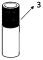
- FIG. 3 Schematic diagram of the shaft tube
- FIG. 4 Schematic diagram of the shaft plate
- Figure 5 Schematic diagram of inverted U-shaped mild steel
- Figure 6 Schematic diagram of the lock nut
- Figure 7 Schematic diagram of the rib joint
- Figure 8 Schematic diagram of the rib top joint
- FIG. 10 Schematic diagram of the top connector
- Figure 11 Schematic diagram of the structure of the unassembled butterfly spring group of the reset energy consuming unit
- Figure 12 Schematic diagram of the assembly of the butterfly assembly with the reset energy consuming unit
- FIG. 13 Schematic diagram of the cable reinforcement and connection unit
- Figure 14 Schematic diagram of the assembly of the cable reinforcement, the connecting unit and the outer groove, and the butterfly spring group
- 1-wing spring group 2-outer groove, 3-axis core tube, 4-axis heart plate, 5-inverted U-shaped mild steel, 6-lock nut, 7-ribbed connector, 8-ribbed connector, 9-bottom connector, 10-top connector, 11-high-strength bolt, 12-tensioned rib, 13-ribbed top anchor, 14-ribbed anchor head.
- the self-resetting metal energy consuming cable of the present invention comprises a reset energy consuming unit, a connecting unit and a tension member.
- the reset energy consuming unit comprises a butterfly spring group 1 for providing a resetting force by pre-compression, a shaft spring tube 1 for connecting the butterfly spring group 1 and the connecting shaft core plate, and locking by screwing into the shaft core tube 3
- the connecting unit includes a rib top joint 8 connected by the rib top anchor head 13 and the tension rib 12, a rib joint head 7 connected by the rib bottom anchor head 14 and the tension rib 12, and a top joint 10 connected to the structure to be reinforced.
- the cable ribs include a high-strength tension rib 12, a rib top anchor head 13 connecting the tension rib 12 and the rib top joint 8, and a rib bottom anchor head 14 connecting the tension rib 12 and the rib bottom joint head 7.
- the structure is shown in Fig. 13, wherein the tension ribs 12 may be steel strands and FRP ribs.
- the butterfly spring group 1 is placed on the shaft support plate 4 and put into the fixed outer groove 2 together, and then the rib top joint head 8, the rib bottom joint head 7 and the shaft core tube 3 are sequentially worn on the tension ribs. 12, and anchoring the ends of the tensioned ribs with the rib top anchor head 13 and the rib bottom anchor head 14 (see Fig. 13), and then passing the shaft tube 3 from the top of the outer tank 2 through the butterfly spring group.
- the self-resetting metal energy-consuming cable of the present invention is installed and used as follows:
- the rib top joint, the rib bottom joint head and the shaft core tube are sequentially inserted into the tension ribs, and then the ends of the tension ribs are anchored by the rib top anchor head 13 and the rib bottom anchor head 14.
- the shaft tube 3 is inserted from the top of the outer tank 2, the butterfly spring group 1 is connected in series, and screwed into the upper end of the shaft of the shaft tray 4.
- the inverted U-shaped mild steel 5 is connected to the shaft center plate 4 and the outer groove 2, respectively, using high-strength bolts 11.
- the tensioned ribs 12 are threaded into the rib joint head 7 and the rib top joint 8 and the ends are anchored by the rib top anchor head 13 and the rib bottom anchor head 14. Then, the rib joint 7 is screwed into the shaft tube 3, the rib top joint 8 is screwed into the top joint head 9, and the outer tank 2 and the bottom end joint 10 are connected by the high-strength bolts 11.
Landscapes
- Engineering & Computer Science (AREA)
- Architecture (AREA)
- Business, Economics & Management (AREA)
- Emergency Management (AREA)
- Environmental & Geological Engineering (AREA)
- Civil Engineering (AREA)
- Structural Engineering (AREA)
- Bridges Or Land Bridges (AREA)
- Reinforcement Elements For Buildings (AREA)
Abstract
Priority Applications (1)
| Application Number | Priority Date | Filing Date | Title |
|---|---|---|---|
| US17/042,939 US10954685B1 (en) | 2018-03-30 | 2018-09-13 | Self-centering cable with metal-based energy-dissipation |
Applications Claiming Priority (2)
| Application Number | Priority Date | Filing Date | Title |
|---|---|---|---|
| CN201810294380.2A CN108590300B (zh) | 2018-03-30 | 2018-03-30 | 自复位金属耗能拉索 |
| CN201810294380.2 | 2018-03-30 |
Publications (1)
| Publication Number | Publication Date |
|---|---|
| WO2019184261A1 true WO2019184261A1 (fr) | 2019-10-03 |
Family
ID=63624399
Family Applications (1)
| Application Number | Title | Priority Date | Filing Date |
|---|---|---|---|
| PCT/CN2018/105367 Ceased WO2019184261A1 (fr) | 2018-03-30 | 2018-09-13 | Câble de dissipation d'énergie métallique à réinitialisation automatique |
Country Status (3)
| Country | Link |
|---|---|
| US (1) | US10954685B1 (fr) |
| CN (1) | CN108590300B (fr) |
| WO (1) | WO2019184261A1 (fr) |
Families Citing this family (9)
| Publication number | Priority date | Publication date | Assignee | Title |
|---|---|---|---|---|
| WO2020103239A1 (fr) * | 2018-11-19 | 2020-05-28 | 扬州大学 | Support de câble de dissipation d'énergie à restauration automatique sans précontrainte |
| CN109372145B (zh) * | 2018-12-06 | 2024-05-14 | 北京市政路桥股份有限公司 | 一种自复位、快修复u型软钢消能支撑 |
| CN110439112B (zh) * | 2019-08-20 | 2024-05-28 | 华南理工大学 | 一种由铰接柱与弹性复位梁组合的免预应力韧性钢结构 |
| CN110836031B (zh) * | 2019-11-25 | 2025-01-24 | 海南大学 | 一种自复位阻尼器及安装方法 |
| CN116446554B (zh) * | 2023-06-16 | 2023-09-05 | 中国建筑第六工程局有限公司 | 一种具有自复位功能的钢狭缝金属阻尼器 |
| CN116676855A (zh) * | 2023-07-21 | 2023-09-01 | 南京现代综合交通实验室 | 一种缓冲耗能结构、防落梁装置及其方法 |
| CN117306734B (zh) * | 2023-09-20 | 2025-09-16 | 同济大学 | 一种低预应力绿色装配式自复位墙 |
| US20250283519A1 (en) * | 2024-03-05 | 2025-09-11 | Pliteq Inc. | Vibration isolation hanger |
| CN118292571B (zh) * | 2024-05-07 | 2025-11-04 | 北京市建筑工程研究院有限责任公司 | 一种销轴连接的变形补偿及耗能传力装置及其安装方法 |
Citations (6)
| Publication number | Priority date | Publication date | Assignee | Title |
|---|---|---|---|---|
| DE102007010701A1 (de) * | 2007-02-27 | 2008-08-28 | Gerb Schwingungsisolierungen Gmbh & Co Kg | Dämpferelement |
| JP2012189104A (ja) * | 2011-03-09 | 2012-10-04 | Shimizu Corp | 慣性質量ダンパー |
| CN103967158A (zh) * | 2014-04-16 | 2014-08-06 | 江苏科技大学 | 一种耗能元件及预应力免屈曲耗能支撑构件 |
| CN105155718A (zh) * | 2015-09-28 | 2015-12-16 | 哈尔滨工业大学 | 摩擦耗能碟簧自复位钢支撑 |
| CN106760010A (zh) * | 2016-12-07 | 2017-05-31 | 上海市建筑科学研究院 | 一种基于碟形弹簧的自复位防屈曲支撑 |
| CN107542177A (zh) * | 2017-09-21 | 2018-01-05 | 长安大学 | 一种自复位耗能器 |
Family Cites Families (35)
| Publication number | Priority date | Publication date | Assignee | Title |
|---|---|---|---|---|
| US2053226A (en) * | 1934-09-01 | 1936-09-01 | Charles W Mowry | Earthquake resistant structure |
| US5347771A (en) * | 1991-06-20 | 1994-09-20 | Kajima Corporation | High damping device for seismic response controlled structure |
| TW295612B (fr) * | 1995-07-21 | 1997-01-11 | Minnesota Mining & Mfg | |
| US5890705A (en) * | 1995-09-20 | 1999-04-06 | Tayco Developments, Inc. | Self-centering liquid spring assembly and constructions thereof |
| US5706626A (en) * | 1995-12-14 | 1998-01-13 | Mueller; Lee W. | Pre-assembled internal shear panel |
| TW305914B (en) * | 1996-10-14 | 1997-05-21 | Hawse Co Ltd | Direction-type active joint and its damping usage |
| US6230450B1 (en) * | 1996-12-27 | 2001-05-15 | Sumitomo Construction Co., Ltd. | Damping top, damping rod, and damping device using same |
| JP3319726B2 (ja) * | 1998-12-10 | 2002-09-03 | 道夫 倉持 | 免震装置 |
| US6510660B1 (en) * | 1999-11-08 | 2003-01-28 | Thk Co., Ltd. | Damping device |
| US6389767B1 (en) * | 2000-01-06 | 2002-05-21 | Zone Four, Llc | Shear wall construction |
| DE10142709A1 (de) * | 2001-08-31 | 2003-11-20 | Maurer Friedrich Soehne | Kraftabsorptionsvorrichtung |
| AU2002360054A1 (en) * | 2001-12-26 | 2003-07-15 | Nihon University, School Juridical Person | Base isolation device for structure |
| US8001734B2 (en) * | 2004-05-18 | 2011-08-23 | Simpson Strong-Tie Co., Inc. | Moment frame links wall |
| US7337586B2 (en) * | 2004-06-14 | 2008-03-04 | Chi-Chang Lin | Anti-seismic device with vibration-reducing units arranged in parallel |
| US7549257B2 (en) * | 2005-07-07 | 2009-06-23 | Kuo-Jung Chuang | Earthquake shock damper |
| TWI396790B (zh) * | 2008-01-24 | 2013-05-21 | Nippon Steel & Sumitomo Metal Corp | 接合金屬件及具有該金屬件之建築物 |
| US20100011681A1 (en) * | 2008-07-21 | 2010-01-21 | Wei-Hua Chiang | Shock Absorber |
| WO2010116779A1 (fr) * | 2009-03-30 | 2010-10-14 | 国立大学法人名古屋大学 | Dispositif de contrôle de vibration pour un corps de châssis à poutrelle |
| JP5740133B2 (ja) * | 2010-02-16 | 2015-06-24 | 大倉 憲峰 | 締結具 |
| US9010230B2 (en) * | 2012-10-24 | 2015-04-21 | Shieldpro, Llc | Anti-ballistic shelters |
| PE20142122A1 (es) * | 2012-01-06 | 2015-01-07 | Oregon State | Riostra de pandeo restringido con construccion ligera |
| US8950055B2 (en) * | 2012-11-14 | 2015-02-10 | Kirk Partridge | Non-penetrating anchor system and method |
| US9683365B2 (en) * | 2014-01-02 | 2017-06-20 | The University Of British Columbia, Okanagan | Piston based self-centering brace apparatus |
| US9896837B2 (en) * | 2014-01-28 | 2018-02-20 | Thor Matteson | Fail-soft, graceful degradation, structural fuse apparatus and method |
| EP2913460B1 (fr) * | 2014-02-19 | 2017-08-23 | Chihiro Sangyo Co., Ltd. | Amortisseur pour un bâtiment |
| US9915078B2 (en) * | 2014-06-18 | 2018-03-13 | Cast Connex Coproration | Structural yielding fuse |
| US9989349B2 (en) * | 2015-07-29 | 2018-06-05 | Corebrace, Llc | Displacement measurement systems and methods |
| US20180266104A1 (en) * | 2015-09-15 | 2018-09-20 | The Regents Of The University Of California | Control system and method for mitigating the effects of natural hazards |
| JP6309170B2 (ja) * | 2015-09-30 | 2018-04-11 | 三菱電機株式会社 | 免震ユニットおよび免震装置 |
| KR101760680B1 (ko) * | 2015-11-23 | 2017-07-26 | 한국전력공사 | 내진 보강 장치 |
| ES2644754B1 (es) * | 2016-04-29 | 2018-09-13 | Tejasa-Tc, S.L.L. | Sistema de protección antisísmica para una losa flotante. |
| KR102005041B1 (ko) * | 2017-06-15 | 2019-07-29 | 한국항공우주연구원 | 복합재 튜브를 이용한 진동충격에너지 흡수장치 및 이를 이용한 건물 제진장치 |
| US10640999B2 (en) * | 2017-07-26 | 2020-05-05 | Steve Cody | Earthquake dampening platform for a ground level storage vessel |
| WO2019031669A1 (fr) * | 2017-08-07 | 2019-02-14 | 인천대학교 산학협력단 | Dispositif amortisseur de renfort automatiquement restaurable et dispositif amortisseur utilisant un matériau intelligent automatiquement restaurable et auto-réparable |
| US10612263B2 (en) * | 2017-10-05 | 2020-04-07 | David McDermott | Columnic actuated spring loader system |
-
2018
- 2018-03-30 CN CN201810294380.2A patent/CN108590300B/zh active Active
- 2018-09-13 US US17/042,939 patent/US10954685B1/en active Active
- 2018-09-13 WO PCT/CN2018/105367 patent/WO2019184261A1/fr not_active Ceased
Patent Citations (6)
| Publication number | Priority date | Publication date | Assignee | Title |
|---|---|---|---|---|
| DE102007010701A1 (de) * | 2007-02-27 | 2008-08-28 | Gerb Schwingungsisolierungen Gmbh & Co Kg | Dämpferelement |
| JP2012189104A (ja) * | 2011-03-09 | 2012-10-04 | Shimizu Corp | 慣性質量ダンパー |
| CN103967158A (zh) * | 2014-04-16 | 2014-08-06 | 江苏科技大学 | 一种耗能元件及预应力免屈曲耗能支撑构件 |
| CN105155718A (zh) * | 2015-09-28 | 2015-12-16 | 哈尔滨工业大学 | 摩擦耗能碟簧自复位钢支撑 |
| CN106760010A (zh) * | 2016-12-07 | 2017-05-31 | 上海市建筑科学研究院 | 一种基于碟形弹簧的自复位防屈曲支撑 |
| CN107542177A (zh) * | 2017-09-21 | 2018-01-05 | 长安大学 | 一种自复位耗能器 |
Also Published As
| Publication number | Publication date |
|---|---|
| CN108590300A (zh) | 2018-09-28 |
| CN108590300B (zh) | 2019-11-12 |
| US20210087843A1 (en) | 2021-03-25 |
| US10954685B1 (en) | 2021-03-23 |
Similar Documents
| Publication | Publication Date | Title |
|---|---|---|
| WO2019184261A1 (fr) | Câble de dissipation d'énergie métallique à réinitialisation automatique | |
| CN109457828B (zh) | 一种双约束自复位防屈曲耗能支撑 | |
| CN109798011B (zh) | 串联碟簧大变形耗能梁柱节点 | |
| CN107386438B (zh) | 翼缘摩擦型形状记忆合金杆自复位钢框架梁-边柱节点 | |
| CN103967158B (zh) | 一种耗能元件及预应力免屈曲耗能支撑构件 | |
| CN209620289U (zh) | 一种双半波弯曲型屈曲约束阻尼器 | |
| CN213926837U (zh) | 一种基于可变摩擦力和多阶段耗能的阻尼器及梁柱节点 | |
| CN105421608A (zh) | 自复位耗能拉索支撑 | |
| CN116497689A (zh) | 柔性防止落梁装置 | |
| JP2020180547A (ja) | 制震装置 | |
| CN103352521A (zh) | 一种单向耗能支撑构件 | |
| CN108532836A (zh) | 一种新型减震自复位耗能拉索支撑装置 | |
| Liu et al. | Assembled self-centering brace with replaceable friction damper for seismic resilience: Development and mechanical behavior research | |
| CN108385520B (zh) | 摩擦型预压弹簧自复位耗能拉索支撑 | |
| CN106245803B (zh) | 一种可调节早期刚度的橡胶阻尼器 | |
| CN120159136A (zh) | 一种摩擦阻尼-碟簧自复位支撑与施工方法 | |
| CN208088124U (zh) | 摩擦型预压弹簧自复位耗能拉索支撑 | |
| CN211473434U (zh) | 一种环向预应力装置 | |
| CN108612217A (zh) | 超弹性形状记忆合金—摩擦耗能串联复合阻尼器 | |
| CN221118231U (zh) | 一种自复位拉索减震支座 | |
| CN118441823A (zh) | 可自复位的防屈曲支撑结构及其自复位方法 | |
| CN114164957B (zh) | 一种震后无损伤自复位钢框架柱 | |
| JPH10238579A (ja) | 構造部材用エネルギー吸収装置 | |
| CN112095832A (zh) | 一种基于预压碟簧的自复位耗能拉索支撑装置 | |
| CN203924395U (zh) | 一种耗能元件及预应力免屈曲耗能支撑构件 |
Legal Events
| Date | Code | Title | Description |
|---|---|---|---|
| 121 | Ep: the epo has been informed by wipo that ep was designated in this application |
Ref document number: 18912854 Country of ref document: EP Kind code of ref document: A1 |
|
| 122 | Ep: pct application non-entry in european phase |
Ref document number: 18912854 Country of ref document: EP Kind code of ref document: A1 |
|
| 122 | Ep: pct application non-entry in european phase |
Ref document number: 18912854 Country of ref document: EP Kind code of ref document: A1 |
|
| 32PN | Ep: public notification in the ep bulletin as address of the adressee cannot be established |
Free format text: NOTING OF LOSS OF RIGHTS PURSUANT TO RULE 112(1) EPC (EPO FORM 1205 DATED 07.05.2021) |
|
| 122 | Ep: pct application non-entry in european phase |
Ref document number: 18912854 Country of ref document: EP Kind code of ref document: A1 |