WO2019186887A1 - Ensemble de soupape d'échappement de moteur à combustion interne - Google Patents
Ensemble de soupape d'échappement de moteur à combustion interne Download PDFInfo
- Publication number
- WO2019186887A1 WO2019186887A1 PCT/JP2018/013223 JP2018013223W WO2019186887A1 WO 2019186887 A1 WO2019186887 A1 WO 2019186887A1 JP 2018013223 W JP2018013223 W JP 2018013223W WO 2019186887 A1 WO2019186887 A1 WO 2019186887A1
- Authority
- WO
- WIPO (PCT)
- Prior art keywords
- rocker arm
- shaft
- valve
- cam
- shaft portion
- Prior art date
- Legal status (The legal status is an assumption and is not a legal conclusion. Google has not performed a legal analysis and makes no representation as to the accuracy of the status listed.)
- Ceased
Links
Images



Classifications
-
- F—MECHANICAL ENGINEERING; LIGHTING; HEATING; WEAPONS; BLASTING
- F01—MACHINES OR ENGINES IN GENERAL; ENGINE PLANTS IN GENERAL; STEAM ENGINES
- F01L—CYCLICALLY OPERATING VALVES FOR MACHINES OR ENGINES
- F01L1/00—Valve-gear or valve arrangements, e.g. lift-valve gear
- F01L1/12—Transmitting gear between valve drive and valve
- F01L1/18—Rocking arms or levers
-
- F—MECHANICAL ENGINEERING; LIGHTING; HEATING; WEAPONS; BLASTING
- F01—MACHINES OR ENGINES IN GENERAL; ENGINE PLANTS IN GENERAL; STEAM ENGINES
- F01L—CYCLICALLY OPERATING VALVES FOR MACHINES OR ENGINES
- F01L1/00—Valve-gear or valve arrangements, e.g. lift-valve gear
- F01L1/20—Adjusting or compensating clearance
- F01L1/22—Adjusting or compensating clearance automatically, e.g. mechanically
Definitions
- the present invention relates to a valve mechanism for an internal combustion engine.
- Patent Document 1 discloses a valve operating mechanism for an internal combustion engine in which a rocker arm shaft is an eccentric shaft, and the eccentric shaft is rotated from the outside of the cylinder head to facilitate tappet clearance adjustment. Yes.
- an object of the present invention is to enable automatic adjustment of tappet clearance while enabling adjustment of tappet clearance using an eccentric shaft as a rocker arm shaft in a valve mechanism of an internal combustion engine.
- One aspect of the present invention includes a camshaft (41) rotatably supported by the engine body (42), a rocker arm shaft (51, 52) rotatably supported by the engine body (42), An engine valve (27, 28) supported by the engine body (42) so as to be opened and closed, and a rocker arm shaft (51, 52) supported by the engine body (42) through a rocker arm shaft (51, 52).
- a rocker arm (47, 48) having a first engagement portion (47d, 48d) engaged with the engine valve (27, 28) and a second engagement portion (47e, 48e) engaged with the engine valve (27).
- the rocker arm shaft (51, 52) includes a support shaft portion (51d, 52d) supported by the engine body (42) and the valve mechanism (40) of the internal combustion engine (10).
- Rocker arm (47, 48) An eccentric shaft portion (51c, 52c) having a second axis (C51, C52) offset from the first axis (C41, C42) of the support shaft portion (51d, 52d),
- the rocker arm shaft (51, 52) further includes a biasing member (53, 54) that applies a biasing force in the circumferential direction, and the rocker arm shaft (51, 52) is attached to the biasing member (53, 54).
- the rocker arm shaft forms an eccentric shaft, and a biasing force in the circumferential direction (rotating direction) is applied to the rocker arm shaft by the biasing member. Then, the rocker arm shaft rotates around the support shaft portion, and the rotational direction position (offset position) of the rocker arm support portion is changed. As a result, the rocker arm can be moved closer to and away from the camshaft and the engine valve, and the tappet clearance can be increased or decreased. If the urging direction of the urging member is a direction that closes the tappet clearance, the tappet clearance can be automatically adjusted (clearance filling) while the tappet clearance can be adjusted using the eccentric shaft for the rocker arm shaft.
- rocker arm shaft (51, 52) applies a rotational driving force against the urging force of the urging member (53, 54) to the rocker arm shaft (51, 52).
- Possible return member (63, 64) and camshaft (41) are provided, and the return member (63, 64) can be operated to apply a rotational driving force to the rocker arm shaft (51, 52).
- Return cams (61, 62) According to this configuration, after the tappet clearance is reduced by the biasing member at the time of cold start of the internal combustion engine, when the temperature of the internal combustion engine rises and each component thermally expands, the rocker arm interferes even when the engine valve is closed. There is a fear.
- the rocker arm shaft is rotated against the biasing force of the biasing member using the return member provided on the rocker arm shaft and the return cam provided on the camshaft.
- the rocker arm shaft returns to the initial state before rotating by the action of the biasing member, and the tappet clearance is packed by the biasing force of the biasing member. Return to the previous set value. In this way, it is possible to prevent only the operation in the direction of closing the tappet clearance by the urging member, and to maintain the tappet clearance at an appropriate value.
- the return cams (61, 62) are such that the rocker arms (47, 48) are in contact with the base circular portions (45a, 46a) of the cams (45, 46) of the cam shaft (41).
- return cam crests (61b, 62b) that can actuate the return members (63, 64) to apply a rotational driving force to the rocker arm shafts (51, 52).
- the rocker arm shaft since the rocker arm shaft is rotated while the rocker arm is not pressing the engine valve, the rocker arm shaft can be rotated without being affected by the reaction force of the valve spring. For this reason, the rocker arm shaft can be easily rotated, the operability of the return mechanism can be improved, and the structure can be simplified.
- valve springs (27e, 28e) for urging the engine valves (27, 28) in a closed state, and the rocker arms (47, 48) of the valve springs (27e, 28e).
- a rotational force acting on the rocker arm shaft (51, 52) by the urging force of the valve spring (27e, 28e) is (T1).
- the rotational force acting on the rocker arm shaft (51, 52) by the urging force of the urging member (53, 54) is (T1 ′)
- the rocker arm shaft (51, 52) is the engine body.
- the rocker arms (47, 48) are supported by the eccentric shaft portions (51c, 52c) via rolling bearings (47f, 48f). According to this configuration, the rocker arm swings smoothly with respect to the rocker arm shaft, the friction torque acting on the rocker arm shaft can be suppressed, and the accompanying rocker arm shaft can be easily prevented.
- the support shaft portion (51d, 52d) is provided on one end side in the axial direction of the rocker arm shaft (51, 52) and supported on one side of the engine body (42).
- the first shaft portion (51a, 52a) and the rocker arm shaft (51, 52) are provided on the other axial end side and supported on the other side of the engine body (42), and the first shaft A second shaft portion (51b, 52b) having a different outer diameter with respect to the portion (51a, 52a),
- the eccentric shaft portion (51c, 52c) is provided between the first shaft portion (51a, 52a) and the second shaft portion (51b, 52b).
- the tappet clearance in the valve mechanism of the internal combustion engine, can be automatically adjusted while the tappet clearance can be adjusted using the eccentric shaft as the rocker arm shaft.
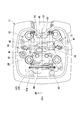
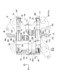
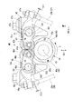
- FIG. 3 is an arrow view corresponding to FIG. 2 including a partial cross section of the valve mechanism of the engine. It is a left view of the said valve mechanism. It is a left view of the return mechanism of the said valve mechanism. It is effect
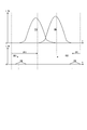
- action explanatory drawing which shows the force which acts on the rocker arm shaft of the said valve mechanism. It is a graph which shows the lift timing of the cam of the said valve mechanism.
- the engine (internal combustion engine) 10 of this embodiment includes a cylinder portion 15 that stands on a crankcase (not shown).
- the cylinder part 15 has a cylinder body 16, a cylinder head 17, and a head cover 18 stacked in order from the crankcase side.
- the engine 10 is an air-cooled single cylinder engine and is used as a prime mover of a small vehicle such as a motorcycle.
- the engine 10 is mounted on the vehicle with the rotation center axis of a crankshaft (not shown) aligned in the vehicle left-right direction.
- the front / rear / right / left directions used in the description of the present embodiment are the same as those in the vehicle unless otherwise specified.
- arrows FR indicating the front of the vehicle
- an arrow LH indicating the left side of the vehicle
- an arrow UP indicating the upper side of the vehicle are shown at appropriate positions in the drawing used to describe the present embodiment.
- a line C2 in the figure indicates an axis (cylinder axis) along the rising direction of the cylinder portion 15.
- a cylindrical cylinder sleeve 15a is integrally inserted.
- a piston 21 is fitted into the cylinder sleeve 15a so as to be able to reciprocate.
- the piston 21 is connected to a crankshaft (not shown) via a connecting rod 22.
- a combustion chamber 23 is formed between the upper surface of the piston 21 and the surface of the cylinder head 17 facing the piston 21.
- the upper part of the cylinder head 17 is formed in a concave shape that opens to the head cover 18 side.
- the cylinder head 17 and the head cover 18 form a valve operating chamber 24 that houses the valve operating mechanism 40.
- the cylinder head 17 is formed with an intake port 25 and an exhaust port 26 each having one end opened to the combustion chamber 23 and the other end opened to the outer surface of the cylinder head 17.
- An annular intake valve seat 25b is fixed to an opening (combustion chamber side opening) 25a on the combustion chamber 23 side of the intake port 25, and an intake valve 27 is arranged to be openable and closable.
- An annular exhaust valve seat 26b is fixed to an opening (combustion chamber side opening) 26a on the combustion chamber 23 side of the exhaust port 26, and an exhaust valve 28 is arranged to be openable and closable.
- the intake valve 27 includes a disk-shaped valve head 27a aligned with the intake valve seat 25b, and a rod-shaped valve stem 27b extending in the normal direction from the center of the upper surface facing the intake port 25 of the valve head 27a. I have.
- the valve stem 27b is inserted in a valve guide 27c press-fitted into the cylinder head 17 so as to be able to reciprocate. The distal end side of the valve stem 27b passes through the valve guide 27c and reaches the valve operating chamber 24.
- a first retainer 27d that supports the upper end of the valve spring 27e is attached to the tip (upper end) of the valve stem 27b.
- a second retainer 27 f that supports the lower end of the valve spring 27 e is attached around the valve guide 27 c on the valve chamber 24 side of the cylinder head 17.
- the valve spring 27e is a compression coil spring that winds around the valve stem 27b, and is contracted between the first retainer 27d and the second retainer 27f. Due to the resilient force of the valve spring 27e, the intake valve 27 is biased upward and closes the combustion chamber side opening 25a of the intake port 25. The intake valve 27 strokes downward (combustion chamber 23 side) against the urging force of the valve spring 27e, thereby opening the combustion chamber side opening 25a of the intake port 25.
- the exhaust valve 28 includes a disc-shaped valve head 28a aligned with the exhaust valve seat 26b, and a rod-shaped valve stem 28b extending in the normal direction from the center of the upper surface facing the exhaust port 26 of the valve head 28a. I have.
- the valve stem 28b is inserted into a valve guide 28c press-fitted into the cylinder head 17 so as to be able to reciprocate.
- the distal end side of the valve stem 28b passes through the valve guide 28c and reaches the valve operating chamber 24.
- a first retainer 28d that supports the upper end of the valve spring 28e is attached to the tip (upper end) of the valve stem 28b.
- a second retainer 28 f that supports the lower end of the valve spring 28 e is attached around the valve guide 28 c on the valve operating chamber 24 side of the cylinder head 17.
- the valve spring 28e is a compression coil spring that winds around the valve stem 28b, and is contracted between the first retainer 28d and the second retainer 28f. Due to the resilient force of the valve spring 28e, the exhaust valve 28 is urged upward to close the combustion chamber side opening 26a of the exhaust port 26. The exhaust valve 28 strokes downward (combustion chamber 23 side) against the biasing force of the valve spring 28e, thereby opening the combustion chamber side opening 26a of the exhaust port 26.
- valve stem 27b of the intake valve 27 and the valve stem 28b of the exhaust valve 28 are disposed to be inclined with respect to the cylinder axis C2.
- the valve stem 27b of the intake valve 27 and the valve stem 28b of the exhaust valve 28 are arranged so as to form a V shape when viewed in the left-right direction (viewed in the axial direction of the crankshaft).
- a camshaft 41 of the valve operating mechanism 40 is disposed between the valve stem 27b of the intake valve 27 and the valve stem 28b of the exhaust valve 28.
- the camshaft 41 is arranged with a rotation center axis (cam axis) C3 along the left-right direction.
- An arrow F in FIG. 1 indicates the rotation direction of the camshaft 41 when the engine 10 is operating.
- the camshaft 41 is supported by a cam holder 42 fixed to the cylinder head 17 so as to be rotatable about the cam axis C3.
- the camshaft 41 can be driven to rotate in cooperation with the crankshaft via, for example, a chain transmission mechanism 43.
- reference numeral 43 a is a cam driven sprocket attached to the left end of the camshaft 41
- reference numeral 43 b is an endless cam chain wound around the cam driven sprocket 43 a
- reference numeral 44 is formed on the left side of the cylinder portion 15 for transmission.
- the cam chain chambers that house the mechanism 43 are shown.
- the intake valve 27 and the exhaust valve 28 are driven to open and close by a valve mechanism 40 including a camshaft 41.
- the valve mechanism 40 includes a camshaft 41 having an intake cam 45 and an exhaust cam 46, an intake rocker arm 47 extending between the intake cam 45 and the stem tip of the intake valve 27, and a stem of the exhaust cam 46 and the exhaust valve 28.
- An exhaust rocker arm 48 extending between the front end, an intake rocker arm shaft 51 that extends parallel to the camshaft 41 and swingably supports the intake rocker arm 47, and an exhaust rocker arm 48 that extends parallel to the camshaft 41.
- an exhaust rocker arm shaft 52 that supports the rocker in a swingable manner.
- the intermediate portion of the cam shaft 41 in the axial direction faces the open portion on the inner side in the left-right direction of the cam holder 42.
- an exhaust cam 45 and an exhaust cam 46 are arranged side by side in the axial direction of the cam shaft 41 in order from the right side, for example.
- the intake cam 45 includes an arc-shaped base circle 45a centered on the cam axis C3, and a cam peak 45b that increases the radial dimension with respect to the base circle 45a. .
- the intake cam 45 forms a smooth elliptical shape in an axial view and forms an endless continuous cam surface.
- the exhaust cam 46 includes an arc-shaped base circle 46a centered on the cam axis C3, and a cam crest 46b that increases the radial dimension with respect to the base circle 46a.
- the exhaust cam 46 forms an endless continuous cam surface in a smooth oval shape when viewed in the axial direction.
- the intake rocker arm 47 includes a cylindrical base portion 47 a that passes through the intake rocker arm shaft 51, an input arm portion 47 b that extends from the base portion 47 a toward the upper side of the intake cam 45, and a base portion 47 a toward the stem tip of the intake valve 27. And an output arm portion 47c extending in an integrated manner.
- a cam roller 47d that is in rolling contact with the outer peripheral surface (cam surface) of the intake cam 45 is rotatably supported at the distal end portion of the input arm portion 47b.
- a tappet bolt 47e that abuts against the stem tip of the intake valve 27 is fixedly supported at the tip of the output arm 47c.
- the exhaust rocker arm 48 includes a cylindrical base portion 48 a that passes through the exhaust rocker arm shaft 52, an input arm portion 48 b that extends from the base portion 48 a toward the upper side of the exhaust cam 46, and a base portion 48 a that faces the stem tip of the exhaust valve 28. And an output arm portion 48c extending in an integrated manner.
- a cam roller 48d that is in rolling contact with the outer peripheral surface (cam surface) of the exhaust cam 46 is rotatably supported at the distal end portion of the input arm portion 48b.
- a tappet bolt 48e that is in contact with the stem tip of the exhaust valve 28 is fixedly supported at the tip of the output arm 48c.
- the intake rocker arm shaft 51 includes a thick shaft portion 51a supported by a left bearing portion 42a on the left side (cam chain 43b side) of the cam holder 42, and a right side of the cam holder 42 (opposite side of the cam chain 43b).
- the eccentric shaft portion 51c supports the base portion 47a of the intake rocker arm 47 via, for example, a needle bearing 47f.
- the thick shaft portion 51a and the thin shaft portion 51b may be collectively referred to as a support shaft portion 51d.
- the thick shaft portion 51a and the thin shaft portion 51b have a cylindrical shape that is coaxial with each other.
- the eccentric shaft portion 51c is shifted in parallel to the thick shaft portion 51a and the thin shaft portion 51b by a distance E on one side in the radial direction. That is, the central axis C51 of the eccentric shaft portion 51c is offset by the distance E from the central axis C41 (the central axis of the entire intake rocker arm shaft 51) of the thick shaft portion 51a and the thin shaft portion 51b.
- the intake rocker arm shaft 51 is rotated about the axis C41, and the rotational direction position of the eccentric shaft portion 51c (the central position of the rotation support of the intake rocker arm 47 by the eccentric shaft portion 51c) is changed.
- the rocker arm 47 can be moved closer to and away from the intake valve 27 to adjust the tappet clearance (valve clearance) cl1.
- the eccentric shaft portion 51c is within the outer diameter of the thick shaft portion 51a as viewed in the axial direction.
- the thin shaft portion 51b is within the outer diameter of the eccentric shaft portion 51c as viewed in the axial direction. That is, the intake rocker arm shaft 51 has the maximum diameter of the outer diameter of the thick shaft portion 51a.
- the eccentric shaft portion 51c and the thin shaft portion 51b do not protrude beyond the outer diameter of the thickest thick shaft portion 51a in the intake rocker arm shaft 51. For this reason, when the intake rocker arm shaft 51 is assembled to the cam holder 42, the intake rocker arm shaft 51 can be inserted from the left bearing portion 42a corresponding to the thick shaft portion 51a toward the right bearing portion 42b.
- the yield of the material at the time of manufacturing the intake rocker arm shaft 51 is improved. Further, since the thin shaft portion 51b is within the outer diameter of the eccentric shaft portion 51c, the base portion 47a of the intake rocker arm 47 can be fitted from the thin shaft portion 51b side.
- the exhaust rocker arm shaft 52 is connected to a thick shaft portion 52a supported by the left bearing portion 42c on the left side (cam chain 43b side) of the cam holder 42 and a right bearing portion 42d on the right side (opposite side of the cam chain 43b) of the cam holder 42.
- a thin shaft portion 52b to be supported, and an eccentric shaft portion 52c provided between the thick shaft portion 52a and the thin shaft portion 52b and supported through the base portion 48a of the exhaust rocker arm 48 are provided.
- the eccentric shaft portion 52c supports the base portion 48a of the exhaust rocker arm 48 via, for example, a needle bearing 48f.
- the thick shaft portion 52a and the thin shaft portion 52b may be collectively referred to as a support shaft portion 52d.
- the thick shaft portion 52a and the thin shaft portion 52b have a cylindrical shape that is coaxial with each other.
- the eccentric shaft portion 52c is displaced in parallel to the thick shaft portion 52a and the thin shaft portion 52b by a distance E ′ on one side in the radial direction. That is, the central axis C52 of the eccentric shaft portion 52c is offset by a distance E ′ from the central axis C42 (the central axis of the exhaust rocker arm shaft 52 as a whole) C42 of the thick shaft portion 52a and the thin shaft portion 52b.
- the exhaust rocker arm shaft 52 is rotated about the axis C42, and the rotational direction position of the eccentric shaft portion 52c (the central position of the rotation support of the exhaust rocker arm 48 by the eccentric shaft portion 52c) is changed.
- the rocker arm 48 can be moved closer to and away from the exhaust valve 28 to adjust the tappet clearance (valve clearance) cl2.
- the eccentric shaft portion 52c is within the outer diameter of the thick shaft portion 52a when viewed in the axial direction.
- the thin shaft portion 52b is within the outer diameter of the eccentric shaft portion 52c as viewed in the axial direction. That is, the exhaust rocker arm shaft 52 has the outer diameter of the thick shaft portion 52a as the maximum diameter.
- the eccentric shaft portion 52c and the thin shaft portion 52b do not protrude beyond the outer diameter of the thickest thick shaft portion 52a in the exhaust rocker arm shaft 52. Therefore, when the exhaust rocker arm shaft 52 is assembled to the cam holder 42, the exhaust rocker arm shaft 52 can be inserted from the left bearing portion 42c corresponding to the thick shaft portion 52a toward the right bearing portion 42d.
- the yield of the material at the time of manufacturing the exhaust rocker arm shaft 52 is improved. Further, since the thin shaft portion 52b fits within the outer diameter of the eccentric shaft portion 52c, the base portion 48a of the exhaust rocker arm 48 can be fitted from the thin shaft portion 52b side.
- the state where the axes C41 and C51 are aligned on a plane orthogonal to the cylinder axis C2, for example, is defined as the initial state of the intake rocker arm shaft 51.
- the eccentric shaft portion 51c (rocker arm support shaft) and the support shaft portion 51d (rocker arm shaft rotation shaft) are at the same height in the direction of the cylinder axis C2.
- a defined tappet clearance cl1 is set between the tappet bolt 47e of the intake rocker arm 47 and the stem tip of the intake valve 27.
- the intake rocker arm shaft 51 rotates (forward rotation) from the initial state, and the eccentric shaft portion 51c is displaced downward (on the cylinder body 16 side), thereby closing the tappet clearance cl1 (set to “0”). Is possible. Further, the tappet clearance cl1 can be widened by rotating (reversing) the intake rocker arm shaft 51 from the initial state and displacing the eccentric shaft portion 51c upward (on the side opposite to the cylinder body 16).
- the state where the axes C42 and C52 are aligned on a plane orthogonal to the cylinder axis C2, for example, is defined as the initial state of the exhaust rocker arm shaft 52.
- the eccentric shaft portion 52c (rocker arm support shaft) and the support shaft portion 52d (rocker arm shaft rotation shaft) are at the same height in the direction of the cylinder axis C2.
- a defined tappet clearance cl2 is set between the tappet bolt 48e of the exhaust rocker arm 48 and the stem tip of the exhaust valve 28.
- the exhaust rocker arm shaft 52 rotates (normally rotates) from the initial state, and the eccentric shaft portion 52c is displaced downward (on the cylinder body 16 side), thereby filling the tappet clearance cl2 (set to “0”). Is possible. Further, the tappet clearance cl2 can be widened by rotating (reversing) the exhaust rocker arm shaft 52 from the initial state and displacing the eccentric shaft portion 52c upward (on the opposite side to the cylinder body 16).
- an intake torsion spring 53 is attached to an end portion (right end portion) of the intake rocker arm shaft 51 opposite to, for example, the cam chain 43b.
- the intake torsion spring 53 is a torsion coil spring that winds around the intake rocker arm shaft 51. One end of the coil is engaged with the cylinder head 17, and the other coil end is engaged with the intake rocker arm shaft 51. It has stopped.
- the intake torsion spring 53 applies a rotational biasing force to the intake rocker arm shaft 51 in one direction (for example, counterclockwise in FIG. 4) around the axis C41.
- the intake rocker arm shaft 51 is biased by the biasing force of the intake torsion spring 53 so as to displace the eccentric shaft portion 51c downward (on the cylinder body 16 side) from the initial state.
- An exhaust torsion spring 54 is attached to, for example, the end (right end) of the exhaust rocker arm shaft 52 opposite to the cam chain 43b.
- the exhaust torsion spring 54 is a torsion coil spring that winds around the exhaust rocker arm shaft 52. One end of the coil is locked to the cylinder head 17, and the other coil end is locked to the exhaust rocker arm shaft 52. is doing.
- the exhaust torsion spring 54 applies a rotational biasing force to the exhaust rocker arm shaft 52 in one direction (for example, clockwise direction in FIG. 4) around the axis C42.
- the exhaust rocker arm shaft 52 is biased by the biasing force of the exhaust torsion spring 54 so as to displace the eccentric shaft portion 52c downward (on the cylinder body 16 side) from the initial state.
- an intake rocker arm shaft 51 and an exhaust rocker arm shaft 52 are respectively attached to an end portion of the cam shaft 41 on the cam chain 43 b side, for example, and a torsion spring 53. , 54 is configured to rotate in a direction against the urging force.
- the return mechanism 60 includes an intake return cam 61 and an exhaust return cam 62 provided at the end of the camshaft 41, and an intake return arm 63 provided at each end of the intake rocker arm shaft 51 and the exhaust rocker arm shaft 52. And an exhaust return arm 64.
- the intake return arm 63 has a proximal end fixed to the end of the intake rocker arm shaft 51.
- a return cam roller 63 d that is in rolling contact with the outer peripheral surface (cam surface) of the intake return cam 61 is supported at the tip of the intake return arm 63.
- the intake return arm 63 shown in FIG. 5 is in a state when the intake rocker arm shaft 51 is in the initial state. This state is the initial state of the intake return arm 63.
- the exhaust return arm 64 has a base end fixed to the end of the exhaust rocker arm shaft 52.
- a return cam roller 64 d that is in rolling contact with the outer peripheral surface (cam surface) of the exhaust return cam 62 is supported at the tip of the exhaust return arm 64.
- the exhaust return arm 64 shown in FIG. 5 is in a state when the exhaust rocker arm shaft 52 is in the initial state. This state is the initial state of the exhaust return arm 64.
- the intake return cam 61 includes an arc-shaped return base circle 61a centered on the cam axis C3 and a return cam crest that increases the radial dimension relative to the return base circle 61a. 61b.
- the return cam crest 61b is arranged in a range H1 that avoids the cam crest 45b of the intake cam 45 when viewed in the axial direction (a range that does not overlap in the rotation direction). In other words, the intake cam 45 and the intake return cam 61 are out of phase with each other.
- the return cam crest 61b has a height for rolling the return cam roller 63d when the intake return arm 63 is in the initial state.
- the intake rocker arm shaft 51 rotates (reverses) from the initial state, displaces the eccentric shaft portion 51c upward (on the side opposite to the cylinder body 16), and temporarily widens the tappet clearance cl1.
- the return cam roller 63d is separated from the return base circle portion 61a in the radial direction.
- the exhaust return cam 62 includes an arc-shaped return base circle portion 62a centered on the cam axis C3 and a return cam crest portion 62b whose radial dimension is increased with respect to the return base circle portion 62a.
- the return cam crest 62b is disposed in a range that avoids the cam crest 46b of the exhaust cam 46 as viewed in the axial direction (a range that does not overlap in the rotation direction). In other words, the exhaust cam 46 and the exhaust return cam 62 are offset from each other in lift timing.
- the return cam crest 62b has a height for rolling the return cam roller 64d when the exhaust return arm 64 is in the initial state.
- the exhaust rocker arm shaft 52 rotates (forward) from the initial state, displaces the eccentric shaft portion 52c upward (on the opposite side to the cylinder body 16), and temporarily widens the tappet clearance cl2.
- the return cam roller 64d is separated from the return base circle 62a in the radial direction.
- the return cam crest 62b passes through the engagement position with the intake return arm 63, and the application of the rotational driving force to the intake rocker arm shaft 51 is eliminated. Then, the intake rocker arm shaft 51 is rotated forward by the urging force of the intake torsion spring 53, and the tappet clearance cl1 is reduced.
- the cam roller 48d of the exhaust rocker arm 48 descends from the cam crest 46b of the exhaust cam 46 and rolls into contact with the base circle 46a.
- the return cam crest 62b of the exhaust return cam 62 rolls the return cam roller 64d of the exhaust return arm 64 in a range H2 that avoids the cam crest 46b of the exhaust cam 46 in the rotation direction of the camshaft 41.
- the exhaust rocker arm shaft 52 is given a rotational driving force in a direction opposite to the biasing force of the exhaust torsion spring 54, and the exhaust rocker arm shaft 52 reverses from the initial state to temporarily widen the tappet clearance cl2.
- Each rocker arm shaft 51, 52 receives the spring force from each valve spring 27 e, 28 e when each valve 27, 28 is opened, thereby displacing the eccentric shaft portions 51 c, 52 c to the opposite side of the cylinder body 16. It is conceivable to rotate like this. However, each rocker resists the friction between each rocker arm shaft 51, 52 and cam holder 42, etc. and the biasing force of each torsion spring 53, 54 due to the spring force perpendicular to each rocker arm shaft 51, 52. It is difficult to rotate the arm shafts 51 and 52.
- the spring reaction force (valve spring load) of the valve spring 27e when the valve 27 is pressed and opened by the tip of the tappet bolt 47e (corresponding to a force point) is F1
- the rotation center (fulcrum) of the cam roller 47d is equivalent to L2 and the distance from the rotation center of the cam roller 47d to the tip of the tappet bolt 47e is L1, the eccentricity due to the valve spring load F1.
- a force (eccentric shaft pushing force) F2 for pushing up the core shaft portion 51c is obtained by the following formula 1.
- F2 F1 * L1 / L2 Formula 1
- T1 F2 * E Equation 2 (E is the eccentric distance of the eccentric shaft portion 51c)
- the friction torque (friction torque) T2 around the diameter D3 of the eccentric shaft portion 51c due to the valve spring load F1 is obtained by the following equation 3.
- T2 F2 * ⁇ * D3 / 2 Formula 3 ( ⁇ is the friction coefficient of the outer periphery of the eccentric shaft portion 51c)
- the friction torque T2 also has a reverse rotation.
- Formula 5 (It is assumed that the valve spring load F1 is applied to the thick shaft portion 51a and the thin shaft portion 51b by half.)
- the residual torque Ta obtained by subtracting various friction torques including the support shaft friction torque Tf from the total torque T3 due to the valve spring load F1 is obtained by the following equation (6).
- ⁇ To F1 * L1 / L2 (E + ⁇ (2D3-D1-D2) / 4)
- T2 the friction addition torque by the friction addition mechanism for the rocker arm shaft 51
- each value is set so as to satisfy the following expression 10. (T1 ′ + Tf + To) ⁇ T1> 0 Expression 10
- rocker arm shafts 51 and 52 rotate along with the swinging of the rocker arms 47 and 48 and rotate in the direction of unintentionally expanding the tappet clearances cl1 and cl2 against the urging force of the torsion springs 53 and 54. Can be prevented.
- the valve mechanism 40 of the engine 10 in the above embodiment includes the camshaft 41 that is rotatably supported by the engine body (cam holder 42), and the rocker arm shaft that is rotatably supported by the engine body. 51, 52, intake / exhaust valves 27, 28 supported by the engine body so as to be openable and closable, and supported by the engine body through rocker arm shafts 51, 52 so as to be swingable and engaged with the camshaft 41.
- the rocker arm shafts 51 and 52 support the support shaft portions 51d and 52d supported by the engine body and the rocker arms 47 and 48, respectively. And eccentric shaft portions 51c, 52c having second axes C51, C52 offset from the first axes C41, C42 of the support shaft portions 51d, 52d, and the rocker arm shafts 51, 52 in the circumferential direction.
- the rocker arm shafts 51 and 52 receive the biasing force of the torsion springs 53 and 54, and the first axis C41 of the shaft portions 51d and 52d.
- the rocker arm shafts 51 and 52 form an eccentric shaft, and a biasing force in the circumferential direction (rotation direction) is applied to the rocker arm shafts 51 and 52 by the torsion springs 53 and 54. Then, the rocker arm shafts 51 and 52 rotate around the support shaft portions 51d and 52d, and the rotational direction positions (offset positions) of the eccentric shaft portions 51c and 52c are changed.
- the rocker arms 47 and 48 are moved closer to and away from the camshaft 41 and the intake and exhaust valves 27 and 28, and the tappet clearances cl1 and cl2 can be increased or decreased. If the urging directions of the torsion springs 53 and 54 are directions to close the tappet clearances cl1 and cl2, the tappet clearances cl1 and cl2 can be adjusted using the eccentric shafts on the rocker arm shafts 51 and 52, and the tappet clearances are adjusted. Automatic adjustment (clearance filling) of cl1 and cl2 can be performed.
- a rotational driving force that is provided on the rocker arm shafts 51 and 52 and resists the biasing force of the torsion springs 53 and 54 can be applied to the rocker arm shafts 51 and 52.
- Return arms 63, 64, and return cams 61, 62 provided on the camshaft 41 and capable of operating the return arms 63, 64 to apply a rotational driving force to the rocker arm shafts 51, 52. Yes.
- the intake / exhaust valve 27 , 28 may interfere with the rocker arms 47, 48.
- the rocker arm shafts 51, 52 are attached to the torsion springs 53, 54 using the return arms 63, 64 provided on the rocker arm shafts 51, 52 and the return cams 61, 62 provided on the camshaft 41. Rotate against power. As a result, every time the camshaft 41 rotates (every cycle of the engine 10), the rocker arm shafts 51 and 52 return to the initial state before rotating by the action of the torsion springs 53 and 54, and the tappet clearance cl1, It returns to the predetermined set value before cl2 is packed by the urging force of the torsion springs 53 and 54. Thus, it is possible to prevent the torsion springs 53 and 54 from repeating only the operation in the direction of closing the tappet clearances cl1 and cl2, and to maintain the tappet clearances cl1 and cl2 at appropriate values.
- the return cams 61 and 62 are arranged so that the rocker arms 47 and 48 are in contact with the base circular portions 45 a and 46 a of the intake and exhaust cams 45 and 46 of the camshaft 41.
- Return cam crests 61b and 62b are provided that can operate the return arms 63 and 64 to apply a rotational driving force to the rocker arm shafts 51 and 52.
- the return cam crest portions 61b and 62b 63 and 64 are operated to apply a rotational driving force to the rocker arm shafts 51 and 52. That is, since the rocker arm shafts 51 and 52 are rotated in a state where the rocker arms 47 and 48 are not pressing the intake and exhaust valves 27 and 28, the rocker arm shafts 51 and 52 are affected by the reaction force of the valve springs 27e and 28e. It can be rotated without receiving. For this reason, the rocker arm shafts 51 and 52 can be easily rotated, the operability of the return mechanism 60 can be improved, and the structure can be simplified.
- the valve mechanism 40 of the engine 10 includes valve springs 27e and 28e that urge the intake and exhaust valves 27 and 28 in a closed state, and the rocker arms 47 and 48 resist the urging force of the valve springs 27e and 28e.
- the intake / exhaust valves 27 and 28 are pressed, the rotational force acting on the rocker arm shafts 51 and 52 via the eccentric shaft portions 51c and 52c is biased by the biasing force of the valve springs 27e and 28e.
- the rotational force acting on the rocker arm shafts 51 and 52 by the biasing force of the core shaft push-up torque T1 and the torsion springs 53 and 54 is the spring biasing torque T1 ′
- the rocker arm shafts 51 and 52 are
- the friction torque received from the main body is the support shaft friction torque Tf
- the rocker arm shafts 51 and 52 are Assuming that the friction torque received from the motors 47 and 48 is the friction addition torque To, the (T1), (T1 ′), (Tf), and (To) are set so as to satisfy the relationship represented by the following expression. .
- the rocker arms 47 and 48 are supported by the eccentric shaft portions 51c and 52c via rolling bearings (needle bearings 47f and 48f). According to this configuration, the rocker arms 47 and 48 swing smoothly with respect to the rocker arm shafts 51 and 52, the friction torque acting on the rocker arm shafts 51 and 52 is suppressed, and the rocker arm shafts 51 and 52 are rotated together. Can be easily prevented.
- the support shaft portions 51 d and 52 d are provided on one end side in the axial direction of the rocker arm shafts 51 and 52 and are supported on one side of the cam holder 42. , 52a and the rocker arm shafts 51, 52 on the other end side in the axial direction, supported on the other side of the cam holder 42, and a thin shaft having a different outer diameter from the thick shaft portions 51a, 52a. Portions 51b and 52b, and the eccentric shaft portions 51c and 52c are provided between the thick shaft portions 51a and 52a and the thin shaft portions 51b and 52b.
- the present invention is not limited to the above-described embodiment.
- the present invention relates to application to an internal combustion engine of a small vehicle such as a motorcycle (saddle-ride type vehicle).
- a small vehicle such as a motorcycle (saddle-ride type vehicle).
- the present invention can be applied to various transport equipment such as passenger cars other than saddle-ride type vehicles. You may apply to an internal combustion engine provided with two or more at least one of the intake and exhaust valves. You may apply to an internal combustion engine provided with two or more camshafts.
- the rocker arm may be configured so that the slipper surface instead of the cam roller is in sliding contact with the cam surface.
- the rocker arm may be configured to press the valve with a pressing portion instead of the tappet bolt.
- the rocker arm may have a sliding bearing such as a metal bush instead of a rolling bearing such as a needle bearing.
- each return cam instead of configuring each return cam with intake and exhaust, a single return cam is configured at a position where timing does not overlap with the exhaust cam and intake cam, and one return cam is shared by two return arms. May be used.
- the configuration in the above embodiment is an example of the present invention, and various modifications can be made without departing from the gist of the present invention, such as replacing the component of the embodiment with a known component.
Landscapes
- Engineering & Computer Science (AREA)
- Mechanical Engineering (AREA)
- General Engineering & Computer Science (AREA)
- Valve-Gear Or Valve Arrangements (AREA)
- Valve Device For Special Equipments (AREA)
Abstract
Priority Applications (4)
| Application Number | Priority Date | Filing Date | Title |
|---|---|---|---|
| CN201880091682.8A CN111902614B (zh) | 2018-03-29 | 2018-03-29 | 内燃机的气门传动机构 |
| JP2020508699A JP6890208B2 (ja) | 2018-03-29 | 2018-03-29 | 内燃機関の動弁機構 |
| BR112020019621-5A BR112020019621B1 (pt) | 2018-03-29 | Mecanismo de trem da válvula de motor de combustão interna | |
| PCT/JP2018/013223 WO2019186887A1 (fr) | 2018-03-29 | 2018-03-29 | Ensemble de soupape d'échappement de moteur à combustion interne |
Applications Claiming Priority (1)
| Application Number | Priority Date | Filing Date | Title |
|---|---|---|---|
| PCT/JP2018/013223 WO2019186887A1 (fr) | 2018-03-29 | 2018-03-29 | Ensemble de soupape d'échappement de moteur à combustion interne |
Publications (1)
| Publication Number | Publication Date |
|---|---|
| WO2019186887A1 true WO2019186887A1 (fr) | 2019-10-03 |
Family
ID=68059686
Family Applications (1)
| Application Number | Title | Priority Date | Filing Date |
|---|---|---|---|
| PCT/JP2018/013223 Ceased WO2019186887A1 (fr) | 2018-03-29 | 2018-03-29 | Ensemble de soupape d'échappement de moteur à combustion interne |
Country Status (3)
| Country | Link |
|---|---|
| JP (1) | JP6890208B2 (fr) |
| CN (1) | CN111902614B (fr) |
| WO (1) | WO2019186887A1 (fr) |
Cited By (1)
| Publication number | Priority date | Publication date | Assignee | Title |
|---|---|---|---|---|
| WO2021199354A1 (fr) * | 2020-03-31 | 2021-10-07 | 本田技研工業株式会社 | Mécanisme de soupape de moteur à combustion interne |
Citations (5)
| Publication number | Priority date | Publication date | Assignee | Title |
|---|---|---|---|---|
| US2772667A (en) * | 1950-01-13 | 1956-12-04 | Daimler Benz Ag | Valve-control |
| JPS59150911U (ja) * | 1983-03-29 | 1984-10-09 | スズキ株式会社 | エンジンのロツカ−ア−ムバルブクリアランス自動調節装置 |
| JPS60195314A (ja) * | 1984-03-16 | 1985-10-03 | Honda Motor Co Ltd | 内燃機関の頭上カムシヤフト式動弁装置 |
| JPH0188005U (fr) * | 1987-12-04 | 1989-06-09 | ||
| JPH0228505U (fr) * | 1988-08-16 | 1990-02-23 |
Family Cites Families (3)
| Publication number | Priority date | Publication date | Assignee | Title |
|---|---|---|---|---|
| EP0331901B1 (fr) * | 1988-02-05 | 1993-11-18 | Dieter Voigt | Entraînement de soupape pour une soupape à levée |
| JP4254582B2 (ja) * | 2004-03-12 | 2009-04-15 | 日産自動車株式会社 | 内燃機関のバルブリフト量調整機構および調整方法 |
| JP4381188B2 (ja) * | 2004-03-19 | 2009-12-09 | 三菱ふそうトラック・バス株式会社 | 内燃機関の可変動弁装置 |
-
2018
- 2018-03-29 CN CN201880091682.8A patent/CN111902614B/zh active Active
- 2018-03-29 JP JP2020508699A patent/JP6890208B2/ja active Active
- 2018-03-29 WO PCT/JP2018/013223 patent/WO2019186887A1/fr not_active Ceased
Patent Citations (5)
| Publication number | Priority date | Publication date | Assignee | Title |
|---|---|---|---|---|
| US2772667A (en) * | 1950-01-13 | 1956-12-04 | Daimler Benz Ag | Valve-control |
| JPS59150911U (ja) * | 1983-03-29 | 1984-10-09 | スズキ株式会社 | エンジンのロツカ−ア−ムバルブクリアランス自動調節装置 |
| JPS60195314A (ja) * | 1984-03-16 | 1985-10-03 | Honda Motor Co Ltd | 内燃機関の頭上カムシヤフト式動弁装置 |
| JPH0188005U (fr) * | 1987-12-04 | 1989-06-09 | ||
| JPH0228505U (fr) * | 1988-08-16 | 1990-02-23 |
Cited By (1)
| Publication number | Priority date | Publication date | Assignee | Title |
|---|---|---|---|---|
| WO2021199354A1 (fr) * | 2020-03-31 | 2021-10-07 | 本田技研工業株式会社 | Mécanisme de soupape de moteur à combustion interne |
Also Published As
| Publication number | Publication date |
|---|---|
| JPWO2019186887A1 (ja) | 2021-03-11 |
| CN111902614A (zh) | 2020-11-06 |
| JP6890208B2 (ja) | 2021-06-18 |
| BR112020019621A2 (pt) | 2021-01-05 |
| CN111902614B (zh) | 2021-12-21 |
Similar Documents
| Publication | Publication Date | Title |
|---|---|---|
| US7726271B2 (en) | Engine with decompression device | |
| US6854435B2 (en) | Variable duration valve timing camshaft | |
| US8820284B2 (en) | Variable valve gear for internal combustion engine | |
| US7913658B2 (en) | Valve actuating mechanism for an internal combustion engine, and cylinder head incorporating same | |
| JP4134587B2 (ja) | 動弁装置およびこれを備えた内燃機関 | |
| CN105422205B (zh) | 引擎的气门机构 | |
| US10364709B2 (en) | Variable valve mechanism, engine, and automatic two-wheeled vehicle | |
| JP6890208B2 (ja) | 内燃機関の動弁機構 | |
| AU2004242531B2 (en) | Valve operating system for internal combustion engine | |
| US10280846B2 (en) | Valve opening and closing timing control device | |
| US7938089B2 (en) | Valve actuating mechanism for an internal combustion engine, and cylinder head incorporating same | |
| WO2021199354A1 (fr) | Mécanisme de soupape de moteur à combustion interne | |
| JP2011058474A (ja) | 4サイクルエンジン | |
| JP6887001B2 (ja) | デコンプ装置を備えたエンジン | |
| US6732693B2 (en) | Valve-operating assembly of driven rotation member and cam | |
| US10309267B2 (en) | Variable valve mechanism, engine, and automatic two-wheeled vehicle | |
| WO2015079916A1 (fr) | Moteur sohc à cylindre unique et culbuteur pour moteur sohc à cylindre unique | |
| BR112020019621B1 (pt) | Mecanismo de trem da válvula de motor de combustão interna | |
| US20090173300A1 (en) | Cam follower device | |
| JP6002648B2 (ja) | スロットルボディ | |
| JP2017150453A (ja) | 内燃機関用動弁装置におけるカム位相可変機構 | |
| JP2013087676A (ja) | エンジンの動弁装置 | |
| JP2006291913A (ja) | 内燃機関の可変動弁装置 | |
| US10253658B2 (en) | Overhead valve actuation mechanism for engine | |
| JP2000097004A (ja) | 3次元カム用バルブリフタの回り止め機構 |
Legal Events
| Date | Code | Title | Description |
|---|---|---|---|
| 121 | Ep: the epo has been informed by wipo that ep was designated in this application |
Ref document number: 18913100 Country of ref document: EP Kind code of ref document: A1 |
|
| DPE1 | Request for preliminary examination filed after expiration of 19th month from priority date (pct application filed from 20040101) | ||
| ENP | Entry into the national phase |
Ref document number: 2020508699 Country of ref document: JP Kind code of ref document: A |
|
| NENP | Non-entry into the national phase |
Ref country code: DE |
|
| REG | Reference to national code |
Ref country code: BR Ref legal event code: B01A Ref document number: 112020019621 Country of ref document: BR |
|
| ENP | Entry into the national phase |
Ref document number: 112020019621 Country of ref document: BR Kind code of ref document: A2 Effective date: 20200925 |
|
| 122 | Ep: pct application non-entry in european phase |
Ref document number: 18913100 Country of ref document: EP Kind code of ref document: A1 |