WO2019187128A1 - Batterie et bloc-batterie - Google Patents
Batterie et bloc-batterie Download PDFInfo
- Publication number
- WO2019187128A1 WO2019187128A1 PCT/JP2018/013919 JP2018013919W WO2019187128A1 WO 2019187128 A1 WO2019187128 A1 WO 2019187128A1 JP 2018013919 W JP2018013919 W JP 2018013919W WO 2019187128 A1 WO2019187128 A1 WO 2019187128A1
- Authority
- WO
- WIPO (PCT)
- Prior art keywords
- negative electrode
- active material
- battery
- electrode active
- containing layer
- Prior art date
- Legal status (The legal status is an assumption and is not a legal conclusion. Google has not performed a legal analysis and makes no representation as to the accuracy of the status listed.)
- Ceased
Links
Images



Classifications
-
- H—ELECTRICITY
- H01—ELECTRIC ELEMENTS
- H01M—PROCESSES OR MEANS, e.g. BATTERIES, FOR THE DIRECT CONVERSION OF CHEMICAL ENERGY INTO ELECTRICAL ENERGY
- H01M10/00—Secondary cells; Manufacture thereof
- H01M10/05—Accumulators with non-aqueous electrolyte
- H01M10/052—Li-accumulators
-
- H—ELECTRICITY
- H01—ELECTRIC ELEMENTS
- H01M—PROCESSES OR MEANS, e.g. BATTERIES, FOR THE DIRECT CONVERSION OF CHEMICAL ENERGY INTO ELECTRICAL ENERGY
- H01M4/00—Electrodes
- H01M4/02—Electrodes composed of, or comprising, active material
- H01M4/13—Electrodes for accumulators with non-aqueous electrolyte, e.g. for lithium-accumulators; Processes of manufacture thereof
- H01M4/131—Electrodes based on mixed oxides or hydroxides, or on mixtures of oxides or hydroxides, e.g. LiCoOx
-
- H—ELECTRICITY
- H01—ELECTRIC ELEMENTS
- H01M—PROCESSES OR MEANS, e.g. BATTERIES, FOR THE DIRECT CONVERSION OF CHEMICAL ENERGY INTO ELECTRICAL ENERGY
- H01M10/00—Secondary cells; Manufacture thereof
- H01M10/05—Accumulators with non-aqueous electrolyte
- H01M10/052—Li-accumulators
- H01M10/0525—Rocking-chair batteries, i.e. batteries with lithium insertion or intercalation in both electrodes; Lithium-ion batteries
-
- H—ELECTRICITY
- H01—ELECTRIC ELEMENTS
- H01M—PROCESSES OR MEANS, e.g. BATTERIES, FOR THE DIRECT CONVERSION OF CHEMICAL ENERGY INTO ELECTRICAL ENERGY
- H01M10/00—Secondary cells; Manufacture thereof
- H01M10/42—Methods or arrangements for servicing or maintenance of secondary cells or secondary half-cells
- H01M10/425—Structural combination with electronic components, e.g. electronic circuits integrated to the outside of the casing
-
- H—ELECTRICITY
- H01—ELECTRIC ELEMENTS
- H01M—PROCESSES OR MEANS, e.g. BATTERIES, FOR THE DIRECT CONVERSION OF CHEMICAL ENERGY INTO ELECTRICAL ENERGY
- H01M10/00—Secondary cells; Manufacture thereof
- H01M10/42—Methods or arrangements for servicing or maintenance of secondary cells or secondary half-cells
- H01M10/48—Accumulators combined with arrangements for measuring, testing or indicating the condition of cells, e.g. the level or density of the electrolyte
- H01M10/486—Accumulators combined with arrangements for measuring, testing or indicating the condition of cells, e.g. the level or density of the electrolyte for measuring temperature
-
- H—ELECTRICITY
- H01—ELECTRIC ELEMENTS
- H01M—PROCESSES OR MEANS, e.g. BATTERIES, FOR THE DIRECT CONVERSION OF CHEMICAL ENERGY INTO ELECTRICAL ENERGY
- H01M4/00—Electrodes
- H01M4/02—Electrodes composed of, or comprising, active material
- H01M4/36—Selection of substances as active materials, active masses, active liquids
- H01M4/362—Composites
-
- H—ELECTRICITY
- H01—ELECTRIC ELEMENTS
- H01M—PROCESSES OR MEANS, e.g. BATTERIES, FOR THE DIRECT CONVERSION OF CHEMICAL ENERGY INTO ELECTRICAL ENERGY
- H01M4/00—Electrodes
- H01M4/02—Electrodes composed of, or comprising, active material
- H01M4/36—Selection of substances as active materials, active masses, active liquids
- H01M4/362—Composites
- H01M4/366—Composites as layered products
-
- H—ELECTRICITY
- H01—ELECTRIC ELEMENTS
- H01M—PROCESSES OR MEANS, e.g. BATTERIES, FOR THE DIRECT CONVERSION OF CHEMICAL ENERGY INTO ELECTRICAL ENERGY
- H01M4/00—Electrodes
- H01M4/02—Electrodes composed of, or comprising, active material
- H01M4/36—Selection of substances as active materials, active masses, active liquids
- H01M4/48—Selection of substances as active materials, active masses, active liquids of inorganic oxides or hydroxides
- H01M4/485—Selection of substances as active materials, active masses, active liquids of inorganic oxides or hydroxides of mixed oxides or hydroxides for inserting or intercalating light metals, e.g. LiTi2O4 or LiTi2OxFy
-
- H—ELECTRICITY
- H01—ELECTRIC ELEMENTS
- H01M—PROCESSES OR MEANS, e.g. BATTERIES, FOR THE DIRECT CONVERSION OF CHEMICAL ENERGY INTO ELECTRICAL ENERGY
- H01M4/00—Electrodes
- H01M4/02—Electrodes composed of, or comprising, active material
- H01M4/62—Selection of inactive substances as ingredients for active masses, e.g. binders, fillers
- H01M4/621—Binders
-
- H—ELECTRICITY
- H01—ELECTRIC ELEMENTS
- H01M—PROCESSES OR MEANS, e.g. BATTERIES, FOR THE DIRECT CONVERSION OF CHEMICAL ENERGY INTO ELECTRICAL ENERGY
- H01M4/00—Electrodes
- H01M4/02—Electrodes composed of, or comprising, active material
- H01M4/62—Selection of inactive substances as ingredients for active masses, e.g. binders, fillers
- H01M4/624—Electric conductive fillers
- H01M4/625—Carbon or graphite
-
- H—ELECTRICITY
- H01—ELECTRIC ELEMENTS
- H01M—PROCESSES OR MEANS, e.g. BATTERIES, FOR THE DIRECT CONVERSION OF CHEMICAL ENERGY INTO ELECTRICAL ENERGY
- H01M4/00—Electrodes
- H01M4/02—Electrodes composed of, or comprising, active material
- H01M4/64—Carriers or collectors
-
- H—ELECTRICITY
- H01—ELECTRIC ELEMENTS
- H01M—PROCESSES OR MEANS, e.g. BATTERIES, FOR THE DIRECT CONVERSION OF CHEMICAL ENERGY INTO ELECTRICAL ENERGY
- H01M50/00—Constructional details or processes of manufacture of the non-active parts of electrochemical cells other than fuel cells, e.g. hybrid cells
- H01M50/10—Primary casings; Jackets or wrappings
- H01M50/102—Primary casings; Jackets or wrappings characterised by their shape or physical structure
- H01M50/103—Primary casings; Jackets or wrappings characterised by their shape or physical structure prismatic or rectangular
-
- H—ELECTRICITY
- H01—ELECTRIC ELEMENTS
- H01M—PROCESSES OR MEANS, e.g. BATTERIES, FOR THE DIRECT CONVERSION OF CHEMICAL ENERGY INTO ELECTRICAL ENERGY
- H01M50/00—Constructional details or processes of manufacture of the non-active parts of electrochemical cells other than fuel cells, e.g. hybrid cells
- H01M50/10—Primary casings; Jackets or wrappings
- H01M50/102—Primary casings; Jackets or wrappings characterised by their shape or physical structure
- H01M50/105—Pouches or flexible bags
-
- H—ELECTRICITY
- H01—ELECTRIC ELEMENTS
- H01M—PROCESSES OR MEANS, e.g. BATTERIES, FOR THE DIRECT CONVERSION OF CHEMICAL ENERGY INTO ELECTRICAL ENERGY
- H01M50/00—Constructional details or processes of manufacture of the non-active parts of electrochemical cells other than fuel cells, e.g. hybrid cells
- H01M50/10—Primary casings; Jackets or wrappings
- H01M50/172—Arrangements of electric connectors penetrating the casing
- H01M50/174—Arrangements of electric connectors penetrating the casing adapted for the shape of the cells
- H01M50/178—Arrangements of electric connectors penetrating the casing adapted for the shape of the cells for pouch or flexible bag cells
-
- H—ELECTRICITY
- H01—ELECTRIC ELEMENTS
- H01M—PROCESSES OR MEANS, e.g. BATTERIES, FOR THE DIRECT CONVERSION OF CHEMICAL ENERGY INTO ELECTRICAL ENERGY
- H01M50/00—Constructional details or processes of manufacture of the non-active parts of electrochemical cells other than fuel cells, e.g. hybrid cells
- H01M50/20—Mountings; Secondary casings or frames; Racks, modules or packs; Suspension devices; Shock absorbers; Transport or carrying devices; Holders
- H01M50/204—Racks, modules or packs for multiple batteries or multiple cells
- H01M50/207—Racks, modules or packs for multiple batteries or multiple cells characterised by their shape
- H01M50/211—Racks, modules or packs for multiple batteries or multiple cells characterised by their shape adapted for pouch cells
-
- H—ELECTRICITY
- H01—ELECTRIC ELEMENTS
- H01M—PROCESSES OR MEANS, e.g. BATTERIES, FOR THE DIRECT CONVERSION OF CHEMICAL ENERGY INTO ELECTRICAL ENERGY
- H01M4/00—Electrodes
- H01M4/02—Electrodes composed of, or comprising, active material
- H01M2004/021—Physical characteristics, e.g. porosity, surface area
-
- H—ELECTRICITY
- H01—ELECTRIC ELEMENTS
- H01M—PROCESSES OR MEANS, e.g. BATTERIES, FOR THE DIRECT CONVERSION OF CHEMICAL ENERGY INTO ELECTRICAL ENERGY
- H01M4/00—Electrodes
- H01M4/02—Electrodes composed of, or comprising, active material
- H01M2004/026—Electrodes composed of, or comprising, active material characterised by the polarity
- H01M2004/027—Negative electrodes
-
- H—ELECTRICITY
- H01—ELECTRIC ELEMENTS
- H01M—PROCESSES OR MEANS, e.g. BATTERIES, FOR THE DIRECT CONVERSION OF CHEMICAL ENERGY INTO ELECTRICAL ENERGY
- H01M10/00—Secondary cells; Manufacture thereof
- H01M10/42—Methods or arrangements for servicing or maintenance of secondary cells or secondary half-cells
- H01M10/425—Structural combination with electronic components, e.g. electronic circuits integrated to the outside of the casing
- H01M2010/4271—Battery management systems including electronic circuits, e.g. control of current or voltage to keep battery in healthy state, cell balancing
-
- Y—GENERAL TAGGING OF NEW TECHNOLOGICAL DEVELOPMENTS; GENERAL TAGGING OF CROSS-SECTIONAL TECHNOLOGIES SPANNING OVER SEVERAL SECTIONS OF THE IPC; TECHNICAL SUBJECTS COVERED BY FORMER USPC CROSS-REFERENCE ART COLLECTIONS [XRACs] AND DIGESTS
- Y02—TECHNOLOGIES OR APPLICATIONS FOR MITIGATION OR ADAPTATION AGAINST CLIMATE CHANGE
- Y02E—REDUCTION OF GREENHOUSE GAS [GHG] EMISSIONS, RELATED TO ENERGY GENERATION, TRANSMISSION OR DISTRIBUTION
- Y02E60/00—Enabling technologies; Technologies with a potential or indirect contribution to GHG emissions mitigation
- Y02E60/10—Energy storage using batteries
Definitions
- Embodiments of the present invention relate to a battery and a battery pack.
- Lithium ion secondary batteries are widely used in portable devices, automobiles and storage batteries. Lithium ion secondary batteries are power storage devices that are expected to expand in market size.
- a negative electrode of a lithium ion secondary battery As a negative electrode of a lithium ion secondary battery, a negative electrode containing titanium oxide is used instead of a carbon-based negative electrode. A battery using titanium oxide as a negative electrode active material can be stably charged and discharged quickly.
- a titanium oxide As an example of a titanium oxide, a titanium-based oxide or a lithium-titanium-based oxide having a monoclinic ⁇ -type structure has attracted attention because of its high capacity of 335 mAh / g. Further, a new electrode material containing Ti and Nb has been studied. In particular, in the monoclinic niobium titanium composite oxide represented by TiNb 2 O 7 , Ti is tetravalent to trivalent and Nb is five when N is inserted. Since charge compensation is performed from valence to trivalence, the theoretical capacity is 387 mAh / g.
- An object is to provide a battery capable of suppressing self-discharge and a battery pack equipped with the battery.
- a battery includes a conductive agent including a carbon material, a negative electrode including a negative electrode active material-containing layer including a niobium titanium composite oxide, and a positive electrode.
- the negative electrode active material-containing layer includes a main surface facing the positive electrode.
- a battery pack is provided.
- the battery pack includes the battery according to the embodiment.
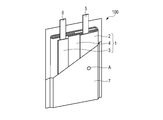
- FIG. 3 is a partially cutaway perspective view showing an example of a battery according to the first embodiment.
- the expanded sectional view of the A section of the battery shown in FIG. The partially cutaway perspective view showing another example of the battery according to the first embodiment.
- the disassembled perspective view which shows an example of the battery pack which concerns on 2nd Embodiment.
- the block diagram which shows an example of the electric circuit of the battery pack shown in FIG.
- a battery includes a conductive agent including a carbon material, a negative electrode including a negative electrode active material-containing layer including a niobium titanium composite oxide, and a positive electrode.
- the negative electrode active material-containing layer includes a main surface facing the positive electrode.
- Niobium titanium composite oxide is insulative even when lithium ions are occluded and released during charge and discharge. Therefore, conventionally, a conductive agent such as a carbon material has been added to a negative electrode containing a niobium titanium composite oxide in order to increase electronic conductivity.
- the carbon material has electronic conductivity regardless of the state of charge of the niobium titanium composite oxide, for example, the state of charge (SOC: State ⁇ ⁇ ⁇ of Charge) of the niobium titanium composite oxide is stored for a long period of time. If this is done, there is a problem that self-discharge tends to proceed and the remaining capacity of the battery tends to decrease.
- SOC State ⁇ ⁇ ⁇ of Charge
- the carbon content on the surface of the negative electrode facing the positive electrode is compared with the carbon content in the vicinity of the center in the thickness direction of the negative electrode active material-containing layer. Small enough.
- the main surface of the negative electrode active material-containing layer facing the positive electrode has a carbon content C1 at a depth of 1 ⁇ m from the main surface.
- the ratio (C2 / C1) of the carbon content C2 at a depth of 0.5 A from the main surface satisfies 2 ⁇ C2 / C1 ⁇ 30. According to such a battery, self-discharge can be suppressed even during long-term storage.
- the carbon contents C1 and C2 are measured by X-ray photoelectron spectroscopy (XPS: X-ray Photoelectron Spectroscopy), and a detailed analysis method of XPS will be described later.
- XPS X-ray Photoelectron spectroscopy
- the battery according to the embodiment includes a negative electrode and a positive electrode.
- the battery according to the embodiment can be, for example, a lithium ion secondary battery or a lithium ion nonaqueous electrolyte secondary battery.
- the battery may further include a separator disposed between the negative electrode and the positive electrode.
- a negative electrode, a positive electrode, and a separator can comprise an electrode group.
- the electrolyte can be held on the electrode group.
- the positive electrode active material-containing layer and the negative electrode active material-containing layer can face each other via a separator.
- the battery can further include an exterior member that accommodates the electrode group and the electrolyte, a negative electrode terminal electrically connected to the negative electrode, and a positive electrode terminal electrically connected to the positive electrode.
- the negative electrode, the positive electrode, the nonaqueous electrolyte, the separator, the exterior member, the negative electrode terminal, and the positive electrode terminal will be described in detail.
- the negative electrode can include a negative electrode current collector and a negative electrode active material-containing layer formed on the negative electrode current collector.
- the negative electrode active material-containing layer contains niobium titanium composite oxide as the negative electrode active material.
- the negative electrode active material-containing layer can contain a conductive agent and a binder.
- the negative electrode current collector can include a portion that does not carry the negative electrode active material-containing layer on the surface. This part can serve as a negative electrode tab. Alternatively, the negative electrode can further include a negative electrode tab separate from the negative electrode current collector.
- FIG. 1 is a cross-sectional view schematically showing an example of a negative electrode included in the battery according to the embodiment.
- the negative electrode 2 includes a negative electrode current collector 2a and a negative electrode active material-containing layer 2b.
- the negative electrode active material-containing layer 2b includes a layered first region 20b stacked on the negative electrode current collector 2a and a second region 21b stacked on the first region 20b.
- the negative electrode current collector 2a has a rectangular foil shape extending in the in-plane direction.
- the negative electrode active material-containing layer 2b has a rectangular sheet shape extending in the in-plane direction. In FIG. 1, the case where the negative electrode active material content layer 2b is laminated
- the negative electrode active material-containing layer 2b may be provided on one surface of the negative electrode current collector 2a.
- the main surface of the negative electrode active material-containing layer 2b refers to a surface having the maximum area among a plurality of surfaces of the negative electrode active material-containing layer 2b.
- the main surface of the negative electrode active material-containing layer 2 b indicates a first surface 50 that is in contact with the negative electrode current collector 2 a and a second surface 51 that faces the first surface. At least a part of the second surface 51 included in the negative electrode active material-containing layer 2b can face a positive electrode (not shown).
- FIG. 1 shows an example in which a clear interface exists between the first region 20b and the second region 21b in the negative electrode active material-containing layer 2b.
- the negative electrode active material content layer 2b which concerns on embodiment does not have a clear interface between the 1st area
- the first region 20b includes a niobium titanium composite oxide, a binder, and a conductive agent including a carbon material.
- the niobium titanium composite oxide has, for example, a particle shape.
- the niobium titanium composite oxide may mainly contain primary particles or may mainly contain secondary particles.
- the niobium titanium composite oxide particles may or may not be covered with the carbon-containing layer.
- the niobium titanium composite oxide particles included in the first region 20b are preferably covered with a carbon-containing layer. In this case, the electronic conductivity of the first region 20b can be greatly increased. In this case, the carbon content C2 described later can be increased in the first region 20b.
- the second region 21b includes a niobium titanium composite oxide and a binder.
- the second region 21b may be made of a niobium titanium composite oxide and a binder.
- the second region 21b does not include a conductive agent including a carbon material.
- the niobium titanium composite oxide particles included in the second region 21b are not covered with the carbon-containing layer. For this reason, in the 2nd field 21b, carbon content C1 mentioned below is small compared with carbon content C2 of the 1st field 20b.
- the first region 20 b includes a depth portion of 0.5 A from the second surface 51.
- the second region 21 b includes a depth portion of 1 ⁇ m from the second surface 51.
- the thickness of the first region 20b is, for example, in the range of 0.88 to 0.97 times A.
- the thickness of the second region 21b is, for example, in the range of 0.03 to 0.12 times A.
- the carbon content C1 of the second region 21b is smaller than the carbon content C2 of the first region 20b. Therefore, if the thickness of the second region 21b is excessively large with respect to the thickness A of the negative electrode active material-containing layer 2b, the input / output characteristics of the battery deteriorate, which is not preferable. Therefore, the thickness of the second region 21b is preferably as thin as possible.
- the thickness A of the negative electrode active material-containing layer 2b is, for example, in the range of 25 ⁇ m to 100 ⁇ m.
- the thickness A of the negative electrode active material-containing layer 2b can be appropriately changed according to the use of the battery. For example, when the battery is used for an application requiring an energy density, the thickness A of the negative electrode active material-containing layer 2b can be made relatively thick. Further, when the battery is used for an application requiring input / output characteristics, the thickness A of the negative electrode active material-containing layer 2b can be made relatively thin.
- the thickness of the first region 20b is, for example, in the range of 22 ⁇ m to 40 ⁇ m.
- the thickness of the first region 20b is a thickness obtained by subtracting the thickness of the second region 21b from the thickness A of the negative electrode active material-containing layer 2b.
- the thickness of the second region 21b from the second surface 51 is, for example, 3 ⁇ m or less.
- the thickness of the second region 21b from the second surface 51 is, for example, in the range of 1 ⁇ m to 3 ⁇ m.
- the thickness of the second region 21b from the second surface 51 is more preferably in the range of 1 ⁇ m to 2 ⁇ m.
- the carbon contents C1 and C2 are analyzed by X-ray photoelectron spectroscopy (XPS: X-ray Photoelectron Spectroscopy).
- the carbon content C1 is the carbon content (atm%) measured by XPS at this depth after shaving from the second surface 51 of the negative electrode active material-containing layer 2b to the first surface 50 to a depth of 1 ⁇ m. ).
- the carbon content C1 can be said to be the carbon content of the second region 21b or the second region 21b.
- the carbon content C2 was cut to a depth of 0.5 A from the second surface 51 of the negative electrode active material-containing layer 2b toward the first surface 50 when the thickness of the negative electrode active material-containing layer 2b was A. This is the carbon content (atm%) later measured by XPS at this depth.
- the carbon content C2 can be said to be the carbon content in the first region 20b or the first region 20b.
- Cycus is a surface / interface cutting test device.
- XPS is performed on the negative electrode taken out from the battery in the following procedure.
- the battery is discharged at a constant current in a constant temperature bath at 25 ° C. until it reaches 1.5 V at a current value [A] corresponding to 0.2 C. Thereafter, constant voltage discharge is performed at 1.5 V for 1 hour.
- the battery is disassembled in an argon glove box.
- the electrode group is taken out from the exterior member in the glove box, and the negative electrode is taken out. At this time, the electrode connected to the negative electrode terminal of the battery can be determined as the negative electrode.
- the taken-out negative electrode is immersed in ethyl methyl carbonate for 10 minutes, taken out and dried. XPS is performed on the negative electrode sample thus prepared.
- Quantera SXM manufactured by PHI As a device for performing XPS, Quantera SXM manufactured by PHI, or a device having a similar function can be used.
- a single crystal spectroscopic Al-K ⁇ (1486.6 eV) is used as the excitation X-ray source, and the photoelectron detection angle is 45 °.
- the ratio of carbon content C2 to carbon content C1 (C2 / C1) satisfies 2 ⁇ C2 / C1 ⁇ 30.
- the ratio (C2 / C1) is 2 or more, the surface layer has a lower electrical conductivity than the inside of the electrode, so that the self-discharge of the secondary battery can be suppressed.
- the ratio (C2 / C1) exceeds 30, the carbon material contained in the electrode is excessive, and there is a concern that the electrolyte decomposition reaction accompanying charge / discharge is likely to occur.
- the ratio (C2 / C1) is preferably 8 ⁇ C2 / C1 ⁇ 21.
- niobium titanium composite oxide for example, a monoclinic niobium titanium composite oxide can be given.
- a compound represented by Li x Ti 1-y M1 y Nb 2 -z M2 z O 7 + ⁇ can be given.
- M1 is at least one selected from the group consisting of Zr, Si, and Sn.
- M2 is at least one selected from the group consisting of V, Ta, and Bi.
- the subscripts in the composition formula are 0 ⁇ x ⁇ 5, 0 ⁇ y ⁇ 1, 0 ⁇ z ⁇ 2, and ⁇ 0.3 ⁇ ⁇ ⁇ 0.3.
- a specific example of the monoclinic niobium titanium complex oxide is Li x Nb 2 TiO 7 (0 ⁇ x ⁇ 5).
- M3 is at least one selected from Mg, Fe, Ni, Co, W, Ta, and Mo.
- the subscripts in the composition formula are 0 ⁇ x ⁇ 5, 0 ⁇ y ⁇ 1, 0 ⁇ z ⁇ 2, and ⁇ 0.3 ⁇ ⁇ ⁇ 0.3.
- the niobium titanium composite oxide may contain one selected from the above compounds, or may contain a mixture of two or more.
- the average primary particle diameter of the niobium titanium composite oxide is, for example, in the range of 0.2 ⁇ m to 5 ⁇ m, and preferably in the range of 0.5 ⁇ m to 2 ⁇ m.
- the average secondary particle diameter of the niobium titanium composite oxide is, for example, in the range of 6 ⁇ m to 25 ⁇ m, and preferably in the range of 8 ⁇ m to 12 ⁇ m.
- the niobium titanium composite oxide included in the second region 21b mainly includes primary particles.
- the average primary particle diameter and average secondary particle diameter of the niobium titanium composite oxide can be measured by SEM-EDX and XRD (X-ray diffraction).
- the cross section of the negative electrode sample taken out by the method described above is cut out by Ar ion milling.
- the active material particles to be measured are observed with a scanning electron microscope (SEM).
- SEM scanning electron microscope
- Some particles are randomly selected in the SEM observation image of 3000 times magnification. At this time, the particle size distribution of the selected particles is selected to be as wide as possible.
- the observed particles contain Ti, Nb, and O, and an X-ray diffraction pattern belonging to TiNb 2 O 7 is obtained from the active material to be measured by XRD measurement described later,
- the active material is identified as TiNb 2 O 7 .
- the composition of the observed secondary particles is analyzed by EDX.
- primary particles and secondary particles containing TiNb 2 O 7 can be specified in the SEM image of the battery active material to be measured.
- the observed active material particles can be estimated by combining the analysis of the XRD diffraction pattern and the result of elemental analysis of each particle contained in the active material to be measured by SEM-EDX.
- SEM observation is used to determine the particle size.
- an image of the active material powder is obtained at a magnification of 3000 times.
- a particle group capable of confirming that the primary particles are in contact is defined as a secondary particle.
- Primary particle size is determined from the diameter of the smallest circle corresponding to the primary particle. Specifically, in the SEM image at a magnification of 3000 times, the particle size is measured 10 times, and the average of the diameters of the smallest circles obtained in each is taken as the primary particle size. For the calculation of the average, the maximum value and the minimum value of the particle diameter are not used among 10 measurements.
- the secondary particle size in the same way as the primary particles. That is, the diameter of the smallest circle corresponding to the secondary particle is obtained. Specifically, in the SEM image at a magnification of 3000 times, the particle size is measured 10 times, and the average of the diameters of the smallest circles obtained in each is taken as the secondary particle size. For the calculation of the average, the maximum value and the minimum value of the particle diameter are not used among 10 measurements.
- XRD X-ray diffraction
- the XRD measurement for the electrode can be performed by cutting the negative electrode taken out by the above-described method to the same extent as the area of the holder of the wide-angle X-ray diffractometer and directly attaching it to the glass holder for measurement.
- the XRD of the current collector is measured, and it is grasped at which position the peak derived from the current collector appears.
- the presence or absence of a peak of a mixture such as a conductive agent or a binder is also grasped in advance.
- the active material-containing layer may be physically peeled off, it is easily peeled off when ultrasonic waves are applied in a solvent. By measuring the active material-containing layer recovered in this way, wide-angle X-ray diffraction measurement of the active material particles can be performed.
- an XRD pattern of the compound contained in the active material particles can be obtained. From the obtained XRD pattern, the crystal structure of the compound contained in the active material particles can be identified.
- the BET specific surface area of the niobium titanium composite oxide particles is not particularly limited, but is preferably 0.1 m 2 / g or more and less than 100 m 2 / g.
- the specific surface area is 0.1 m 2 / g or more, a contact area with the electrolytic solution can be ensured, good discharge rate characteristics can be easily obtained, and the charging time can be shortened.
- the specific surface area is less than 100 m 2 / g, the reactivity with the electrolyte does not become too high, and the life characteristics can be improved.
- the specific surface area is less than 100 m 2 / g, it is possible to improve the coatability of the slurry containing the active material used for manufacturing the electrode described later.
- the negative electrode active material-containing layer may further contain an active material other than the niobium titanium composite oxide.
- active materials other than the niobium titanium composite oxide for example, lithium titanate having a ramsdellite structure (for example, Li 2 + y Ti 3 O 7 , 0 ⁇ y ⁇ 3), lithium titanate having a spinel structure (for example, Li 4 + x Ti 5 O 12 , 0 ⁇ x ⁇ 3), monoclinic titanium dioxide (TiO 2 (B)), anatase type titanium dioxide, rutile type titanium dioxide, hollandite type titanium composite oxide and tetragonal type ( orthorhombic) titanium-containing composite oxide.
- ramsdellite structure for example, Li 2 + y Ti 3 O 7 , 0 ⁇ y ⁇ 3
- lithium titanate having a spinel structure for example, Li 4 + x Ti 5 O 12 , 0 ⁇ x ⁇ 3
- Examples of the tetragonal titanium-containing composite oxide include a compound represented by Li 2 + a M (I) 2 -b Ti 6 -c M (II) d O 14 + ⁇ .
- M (I) is at least one selected from the group consisting of Sr, Ba, Ca, Mg, Na, Cs, Rb and K.
- M (II) is at least one selected from the group consisting of Zr, Sn, V, Nb, Ta, Mo, W, Y, Fe, Co, Cr, Mn, Ni, and Al.
- composition formula 0 ⁇ a ⁇ 6, 0 ⁇ b ⁇ 2, 0 ⁇ c ⁇ 6, 0 ⁇ d ⁇ 6, and ⁇ 0.5 ⁇ ⁇ ⁇ 0.5.
- tetragonal titanium-containing composite oxide include Li 2 + a Na 2 Ti 6 O 14 (0 ⁇ a ⁇ 6).
- the conductive agent is blended in order to improve the current collecting performance and suppress the contact resistance between the active material and the current collector.
- the conductive agent includes a carbon material.
- the carbon material include vapor grown carbon fiber (Vapor Grown Carbon Fiber; VGCF), carbon black, graphite, carbon nanotube, and fullerene.
- Examples of carbon black include acetylene black and ketjen black. One of these may be used as a conductive agent, or a combination of two or more may be used as a conductive agent.
- the surface of the active material particles may be coated with a carbon-containing layer or an electronically conductive inorganic material coat.
- the carbon component contained in the carbon-containing layer will be described.
- the crystallinity of the carbon component can be determined.
- the G band observed near 1580 cm ⁇ 1 is a peak derived from the graphite structure
- the D band observed near 1330 cm ⁇ 1 is a peak derived from the defect structure of carbon. is there.
- G band and D band is due to various factors, from 1580 cm -1 and 1330 cm -1, it is possible that each shifted about ⁇ 50 cm -1.
- Carbon material ratio I G / I D between the peak intensity I D of G peak intensity of the bands I G and D bands in the Raman chart is 0.8 to 1.2, it has a good crystallinity of graphite Means. Such a carbon component can have excellent conductivity.
- a micro-Raman measurement apparatus As a technique for quantitatively evaluating the crystallinity of the carbon component contained in the carbon-containing layer, a micro-Raman measurement apparatus can be used.
- the micro Raman apparatus for example, Thermo Fisher Scientific ALMEGA can be used.
- the measurement conditions can be, for example, a wavelength of the measurement light source of 532 nm, a slit size of 25 ⁇ m, a laser intensity of 10%, an exposure time of 5 s, and an integration count of 10 times.
- Raman spectroscopy can be performed, for example, according to the procedure described below.
- the battery When evaluating the negative electrode active material particles incorporated in the battery, first, the battery is completely discharged in order to completely remove lithium ions from the battery. However, a small amount of lithium ions may remain even in a discharged state.
- the battery is disassembled in a glove box filled with argon, and the electrode is washed with an appropriate solvent. At this time, for example, ethyl methyl carbonate may be used.
- the active material-containing layer is peeled off from the cleaned electrode, and a sample is collected.
- Raman spectroscopy measurement is performed under the conditions described above.
- the presence or absence of Raman activity and the peak position of other components contained in the current collector and the mixture such as the conductive agent and the binder are known.
- a plurality of peaks are overlapped, it is necessary to separate peaks relating to components other than the active material.
- the active material-containing layer when the active material (for example, when the carbon-containing layer is coated on the surface of the niobium titanium composite oxide particles) is mixed with a conductive agent, the carbon material contained in the active material and the conductive material It can be difficult to distinguish between carbon materials incorporated as agents.
- a method for distinguishing between the two for example, a method of dissolving and removing the binder with a solvent and then performing centrifugation to extract an active material having a high specific gravity can be considered. According to such a method, since the active material and the conductive agent can be separated, the carbon material contained in the active material can be subjected to measurement while being contained in the active material. it can.
- mapping is performed from the spectral component derived from the active material by mapping by microscopic Raman spectroscopy to separate the conductive agent component from the active material component, and then only the Raman spectrum corresponding to the active material component is extracted. It is also possible to take an evaluation method.
- the binder is blended to fill the gap between the dispersed active materials and to bind the active material and the negative electrode current collector.
- the binder include polytetrafluoroethylene (PTFE), polyvinylidene fluoride (PVdF), fluorine rubber, styrene butadiene rubber, polyacrylic acid compound, imide compound, carboxymethyl cellulose (carboxymethyl cellulose) CMC), CMC salts, polyimides and polyamides.
- PTFE polytetrafluoroethylene
- PVdF polyvinylidene fluoride
- fluorine rubber fluorine rubber
- styrene butadiene rubber polyacrylic acid compound
- imide compound imide compound
- CMC salts polyimides and polyamides.
- One of these may be used as a binder, or a combination of two or more may be used as a binder.
- the mixing ratio of the negative electrode active material, the conductive agent, and the binder in the first region 20b included in the negative electrode active material-containing layer 2b is 70% by weight to 96% by weight of the negative electrode active material, and 2% by weight to 28% by weight of the conductive agent.
- the binder is preferably 2% by weight or more and 28% by weight or less.
- the mixing ratio of the negative electrode active material and the binder in the second region 21b included in the negative electrode active material-containing layer 2b is 90% by weight to 98% by weight of the negative electrode active material, and 2% by weight to 10% by weight of the binder. It is preferable to do.
- the negative electrode current collector is preferably an aluminum foil or an aluminum alloy foil that is electrochemically stable in a potential range nobler than 1.0 V.
- the negative electrode is formed by simultaneously applying a first slurry for forming the first region 20b included in the negative electrode active material-containing layer 2b and a second slurry for forming the second region 21b to the current collector, It can be produced by drying. In this specification, this case is called two-layer simultaneous coating.
- the negative electrode may be formed by applying the first slurry to the current collector and then drying to form the first region 20b, and then applying the second slurry and then drying the second region on the first region 20b. 21b can be formed. In this specification, this case is called sequential coating.
- the negative electrode active material-containing layer 2b having no clear interface between the first region 20b and the second region 21b can be manufactured.
- a first slurry for forming the first region 20b and a second slurry for forming the second region 21b are formed on at least one of the front and back surfaces of the negative electrode current collector 2a.
- the first slurry is prepared by suspending a niobium titanium composite oxide, a conductive agent, and a binder in an appropriate solvent.
- the second slurry is prepared by suspending a niobium titanium composite oxide and a binder in an appropriate solvent.
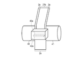
- the coating apparatus 40 includes a tank 42 for storing a first slurry (hereinafter referred to as slurry I) and a tank 43 for storing a second slurry (hereinafter referred to as slurry II), and a base such as a current collector.
- the slurry I and the slurry II are simultaneously applied to the material.
- the width orthogonal to the coating direction at the discharge port of the slurry I corresponds to the coating width of the first region 20b included in the negative electrode active material-containing layer 2b.
- the long negative electrode current collector 2 a before being cut into a predetermined size is conveyed by the conveying roller 41 to the slurry discharge port of the coating apparatus 40.
- the slurry I discharge port 42a is located on the upstream side of the current collector with respect to the slurry II discharge port 43a.
- the width orthogonal to the coating direction of the slurry I discharge port 42a is narrower than the width orthogonal to the coating direction of the slurry II discharge port 43a.
- the slurry I is applied from the coating device 40 onto the negative electrode current collector 2a except for both ends in the short side direction.
- the slurry II is overcoated so as to protrude from the application area of the slurry I. Since the slurry II is repeatedly applied to the slurry I before the slurry I dries, the slurry II easily follows the surface shape of the slurry I. Then, after drying the slurry, the dried product is roll-pressed and cut into a predetermined size to obtain a negative electrode.
- the first slurry is applied to one or both sides of the long negative electrode current collector 2a.
- the applied slurry is dried to obtain a laminate in which the first region 20b is laminated on the negative electrode current collector 2a.
- the second slurry is applied onto the first region 20b.
- the second slurry can be applied onto the first region 20b and the negative electrode current collector 2a with a coating width longer than the length of the first region 20b already formed in the short side direction.
- the applied second slurry is dried to obtain a laminate including the negative electrode current collector 2a, the first region 20b, and the second region 21b.
- the laminate can be pressed and cut into a predetermined size to obtain a negative electrode.
- the positive electrode includes a positive electrode current collector and a positive electrode active material-containing layer (positive electrode material layer) that is supported on one or both surfaces of the positive electrode current collector and includes a positive electrode active material, a positive electrode conductive agent, and a binder. Including.
- a lithium transition metal composite oxide can be used as the positive electrode active material.
- a lithium transition metal composite oxide can be used.
- LiCoO 2 LiNi 1-x Co x O 2 (0 ⁇ x ⁇ 0.3), LiMn x Ni y Co z O 2 (0 ⁇ x ⁇ 0.5,0 ⁇ y ⁇ 0.5,0 ⁇ z ⁇ 0.5), LiMn 2 ⁇ x M x O 4 (M is at least one element selected from the group consisting of Mg, Co, Al and Ni, 0 ⁇ x ⁇ 0.2), LiMPO 4 ( M is at least one element selected from the group consisting of Fe, Co and Ni).
- Li u MeO 2 (Me is at least one selected from the group consisting of Ni, Co, and Mn) having a layered structure.
- lithium nickel composite oxide for example, Li u NiO 2
- lithium cobalt composite oxide for example, Li u CoO 2
- lithium nickel cobalt composite oxide for example, Li u Ni 1-s Co s O 2
- lithium manganese cobalt composite oxide e.g., Li u Mn s Co 1- s O 2
- lithium-nickel-cobalt-manganese composite oxide e.g., Li u Ni 1-st Co s Mn t O 2
- lithium nickel cobalt aluminum Complex oxides for example, Li u Ni 1-st Co s Al t O 2
- lithium manganese complex oxides for example, Li u Ni 1-st Co s Al t O 2
- lithium manganese complex oxides for example, Li u Ni 1-st Co s Al t O 2
- lithium manganese complex oxides having
- a spinel type lithium manganese composite oxide such as Li u Mn 2 O 4 or Li u Mn 2 -s Al s O 4 may be used alone, or a plurality of compounds may be used in combination. .
- Lithium-manganese composite oxides Li u Mn 2 O 4 and Li u Mn 2 -s Al s O 4
- lithium cobalt composite oxides that have a spinel structure because they can easily achieve high input / output performance and excellent lifetime performance
- Li u CoO 2 lithium nickel cobalt composite oxide (Li u Ni 1-s Co s O 2), lithium manganese cobalt composite oxide (Li u Mn s Co 1- s O 2), lithium-nickel-cobalt-manganese composite oxides (e.g., Li u Ni 1-st Co s Mn t O 2), or lithium phosphates having an olivine structure (e.g., Li u FePO 4, Li u MnPO 4, Li u Mn 1-s Fe s PO 4 , Li u CoPO 4 ).
- 0 ⁇ u ⁇ 1, 0 ⁇ s ⁇ 1, and 0 ⁇ t ⁇ 1 are preferable.
- binder examples include, for example, polytetrafluoroethylene (PTFE), polyvinylidene fluoride (PVdF), fluorine rubber, styrene butadiene rubber (SBR), carboxymethyl cellulose (CMC), polyimide, polyamide, and the like.
- PTFE polytetrafluoroethylene
- PVdF polyvinylidene fluoride
- SBR styrene butadiene rubber
- CMC carboxymethyl cellulose
- polyimide polyamide
- polyamide polyamide
- Examples of the positive electrode conductive agent include carbon black such as acetylene black and ketjen black, graphite, carbon fiber, carbon nanotube, and fullerene.
- the type of the conductive agent can be one type or two or more types.
- the mixing ratio of the positive electrode active material, the conductive agent, and the binder in the positive electrode active material-containing layer is 80% by weight to 95% by weight of the positive electrode active material, 3% by weight to 18% by weight of the conductive agent, and 2% by weight of the binder. It is preferable to make it 17% by weight or less.
- the current collector is preferably an aluminum foil or an aluminum alloy foil, and the average crystal grain size is desirably 50 ⁇ m or less, more preferably 30 ⁇ m or less, and even more preferably 5 ⁇ m or less.
- the current collector made of an aluminum foil or aluminum alloy foil having such an average crystal grain size can dramatically increase the strength, and the positive electrode can be densified with a high press pressure. The capacity can be increased.
- Aluminum foil or aluminum alloy foil with an average crystal grain size of 50 ⁇ m or less is affected by many factors such as material composition, impurities, processing conditions, heat treatment history and annealing conditions, and the crystal grain diameter (diameter) Is adjusted by combining the above factors in the manufacturing process.
- the thickness of the current collector is 20 ⁇ m or less, more preferably 15 ⁇ m or less.
- the purity of the aluminum foil is preferably 99% or more.
- As the aluminum alloy an alloy containing elements such as magnesium, zinc, and silicon is preferable.
- the content of transition metals such as iron, copper, nickel and chromium is preferably 1% or less.
- the positive electrode is prepared by suspending a positive electrode active material, a positive electrode conductive agent, and a binder in a suitable solvent, and applying the resulting slurry to a positive electrode current collector and drying to prepare a positive electrode active material-containing layer. It is produced by applying a press.
- the positive electrode active material, the positive electrode conductive agent, and the binder may be formed in a pellet shape and used as the positive electrode active material-containing layer.
- the positive electrode active material-containing layer preferably has a porosity of 20% to 50%.
- a positive electrode provided with a positive electrode active material-containing layer having such a porosity has a high density and is excellent in affinity with a nonaqueous electrolyte. More preferable porosity is 25% or more and 40% or less.
- the density of the positive electrode active material-containing layer is preferably 2.5 g / cm 3 or more.
- Non-aqueous electrolyte examples include a liquid non-aqueous electrolyte prepared by dissolving an electrolyte salt in a non-aqueous solvent, and a gel non-aqueous electrolyte obtained by combining a liquid non-aqueous electrolyte and a polymer material.
- Examples of the electrolyte salt include lithium perchlorate (LiClO 4 ), lithium hexafluorophosphate (LiPF 6 ), lithium tetrafluoroborate (LiBF 4 ), lithium hexafluoroarsenide (LiAsF 6 ), and difluorophosphate.
- Examples include lithium salts such as lithium (LiPO 2 F 2 ), lithium trifluorometasulfonate (LiCF 3 SO 3 ), and lithium bistrifluoromethylsulfonylimide [LiN (CF 3 SO 2 ) 2 ]. These electrolyte salts may be used alone or in combination of two or more.
- the electrolyte salt is preferably dissolved in the range of 0.5 mol / L to 2.5 mol / L with respect to the organic solvent.
- Nonaqueous solvents include, for example, cyclic carbonates such as ethylene carbonate (EC), propylene carbonate (PC), and vinylene carbonate (VC); chains such as dimethyl carbonate (DMC), ethyl methyl carbonate (EMC), and diethyl carbonate (DEC).
- cyclic carbonates such as ethylene carbonate (EC), propylene carbonate (PC), and vinylene carbonate (VC)
- chains such as dimethyl carbonate (DMC), ethyl methyl carbonate (EMC), and diethyl carbonate (DEC).
- Cyclic carbonates cyclic ethers such as tetrahydrofuran (THF), 2-methyltetrahydrofuran (2MeTHF); chain ethers such as dimethoxyethane (DME); cyclic esters such as ⁇ -butyrolactone (BL); methyl acetate, ethyl acetate, methyl propionate And chain esters such as ethyl propionate; acetonitrile (AN); sulfolane (SL) and the like.
- THF tetrahydrofuran
- 2MeTHF 2-methyltetrahydrofuran
- DME dimethoxyethane
- cyclic esters such as ⁇ -butyrolactone (BL); methyl acetate, ethyl acetate, methyl propionate And chain esters such as ethyl propionate; acetonitrile (AN); sulfolane (SL) and the like.
- organic solvents
- polymer material used for the gel-like non-aqueous electrolyte examples include polyvinylidene fluoride (PVdF), polyacrylonitrile (PAN), and polyethylene oxide (PEO).
- PVdF polyvinylidene fluoride
- PAN polyacrylonitrile
- PEO polyethylene oxide
- separator examples include a porous film containing polyethylene, polypropylene, cellulose, or polyvinylidene fluoride (PVdF), and a synthetic resin nonwoven fabric.
- PVdF polyvinylidene fluoride
- Exterior member may be formed from a laminate film or may be composed of a metal container. When a metal container is used, the lid can be integrated with or separate from the container.
- the wall thickness of the metal container is more preferably 0.5 mm or less and 0.2 mm or less.
- Examples of the shape of the exterior member include a flat type, a square type, a cylindrical type, a coin type, a button type, a sheet type, and a laminated type.
- a large battery mounted on a two-wheeled or four-wheeled vehicle may be used.
- the thickness of the laminate film exterior member is 0.2 mm or less.
- the laminate film include a multilayer film including a resin film and a metal layer disposed between the resin films.
- the metal layer is preferably an aluminum foil or an aluminum alloy foil for weight reduction.
- the resin film for example, a polymer material such as polypropylene (PP), polyethylene (PE), nylon, polyethylene terephthalate (PET) can be used.
- the laminate film can be formed into the shape of an exterior member by sealing by heat sealing.
- the metal container is made of aluminum or aluminum alloy.
- the aluminum alloy an alloy containing elements such as magnesium, zinc, and silicon is preferable.
- the content of transition metals such as iron, copper, nickel, and chromium is preferably set to 100 ppm or less in order to drastically improve long-term reliability and heat dissipation in a high temperature environment.
- the metal container made of aluminum or aluminum alloy has an average crystal grain size of 50 ⁇ m or less, more preferably 30 ⁇ m or less, and even more preferably 5 ⁇ m or less.
- the average crystal grain size By setting the average crystal grain size to 50 ⁇ m or less, the strength of a metal container made of aluminum or an aluminum alloy can be dramatically increased, and the container can be made thinner. As a result, it is possible to realize a nonaqueous electrolyte battery that is lightweight, has high output, and is excellent in long-term reliability.
- Negative electrode terminal and positive electrode terminal The negative electrode terminal can work as a conductor for electrons to move between the negative electrode and the external terminal by being partially connected to a part of the negative electrode. .
- the negative electrode terminal can be connected to, for example, a negative electrode current collector, particularly a negative electrode tab.
- the positive electrode terminal can function as a conductor for electrons to move between the positive electrode and an external circuit by being electrically connected to a part of the positive electrode.
- the positive electrode terminal can be connected to, for example, a positive electrode current collector, particularly a positive electrode tab.
- the negative electrode terminal and the positive electrode terminal are preferably formed from a material having high electrical conductivity. When connecting to the current collector, these terminals are preferably made of the same material as the current collector in order to reduce contact resistance.
- FIG. 4 is a partially cutaway perspective view showing an example of the battery according to the embodiment.
- FIG. 5 is an enlarged cross-sectional view of part A of the battery shown in FIG.
- the battery 100 shown in FIGS. 4 and 5 includes a flat electrode group 1.
- the flat electrode group 1 includes a negative electrode 2, a positive electrode 3, and a separator 4.
- the electrode group 1 has a structure in which a negative electrode 2 and a positive electrode 3 are wound in a spiral shape so as to have a flat shape with a separator 4 interposed therebetween.
- the wound electrode group will be described here, the electrode group may be a stacked electrode group in which a plurality of negative electrodes 2, separators 4, and positive electrodes 3 are stacked.
- the negative electrode 2 includes a negative electrode current collector 2a and a negative electrode active material-containing layer 2b supported on the negative electrode current collector 2a.
- the positive electrode 3 includes a positive electrode current collector 3a and a positive electrode active material-containing layer 3b supported on the positive electrode current collector 3a.
- the negative electrode active material-containing layer 2b includes a main surface facing the positive electrode (positive electrode active material-containing layer 3b).
- a strip-like negative electrode terminal 5 is electrically connected to the negative electrode 2. More specifically, the negative electrode terminal 5 is connected to the negative electrode current collector 2a.
- a strip-like positive electrode terminal 6 is electrically connected to the positive electrode 3. More specifically, the positive electrode terminal 6 is connected to the positive electrode current collector 3a.
- the battery 100 further includes an outer packaging container 7 made of a laminate film as a container. That is, the battery 100 includes an exterior member composed of an exterior container 7 made of a laminate film.
- the electrode group 1 is accommodated in an outer packaging container 7 made of a laminate film. However, the end portions of the negative electrode terminal 5 and the positive electrode terminal 6 extend from the outer container 7.
- a non-aqueous electrolyte (not shown) is accommodated in the outer packaging container 7 made of a laminate film. The nonaqueous electrolyte is impregnated in the electrode group 1.
- the outer casing 7 is heat-sealed at the peripheral edge, thereby sealing the electrode group 1 and the non-aqueous electrolyte.
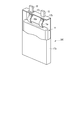
- FIG. 6 is a partially cutaway perspective view showing another example of the battery according to the first embodiment.
- the battery 200 shown in FIG. 6 is different from the battery 100 shown in FIGS. 4 and 5 in that the exterior member is composed of a metal container 17a and a sealing plate 17b.
- the flat electrode group 11 includes a negative electrode, a positive electrode, and a separator, like the electrode group 1 in the battery 100 shown in FIGS. 4 and 5.
- the electrode group 11 has the same structure as the electrode group 1. However, in the electrode group 11, in place of the negative electrode terminal 5 and the positive electrode terminal 6, a negative electrode tab 15a and a positive electrode tab 16a are connected to the negative electrode and the positive electrode, respectively, as described later.
- Such an electrode group 11 is accommodated in the metal container 17a.
- the metal container 17a further stores a non-aqueous electrolyte (not shown).
- the metal container 17a is sealed with a metal sealing plate 17b.
- the metal container 17a and the sealing plate 17b constitute, for example, an outer can as an outer member.
- the negative electrode tab 15 a has one end electrically connected to the negative electrode current collector and the other end electrically connected to the negative electrode terminal 15.
- One end of the positive electrode tab 16a is electrically connected to the positive electrode current collector, and the other end is electrically connected to the positive electrode terminal 16 fixed to the sealing plate 17b.
- the positive terminal 16 is fixed to the sealing plate 17b via an insulating member 17c.
- the positive electrode terminal 16 and the sealing plate 17b are electrically insulated by an insulating member 17c.
- the battery according to the first embodiment includes a negative electrode provided with a conductive agent containing a carbon material, a negative electrode active material-containing layer containing a niobium titanium composite oxide, and a positive electrode.
- the negative electrode active material-containing layer includes a main surface facing the positive electrode.
- a battery pack is provided.
- This battery pack includes the battery according to the first embodiment.
- the battery pack according to the second embodiment can also include a plurality of batteries.
- the plurality of batteries can be electrically connected in series or electrically connected in parallel.
- a plurality of batteries can be connected in a combination of series and parallel.
- the battery pack according to the second embodiment may include, for example, five batteries. These batteries can be connected in series. Moreover, the battery connected in series can comprise an assembled battery. That is, the battery pack according to the second embodiment can include an assembled battery.
- the battery pack according to the second embodiment can include a plurality of assembled batteries.
- the plurality of assembled batteries can be connected in series, parallel, or a combination of series and parallel.
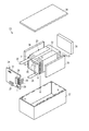
- FIG. 7 is an exploded perspective view showing an example of the battery pack according to the second embodiment.
- FIG. 8 is a block diagram showing an example of an electric circuit of the battery pack shown in FIG.
- the battery pack 20 shown in FIGS. 7 and 8 includes a plurality of unit cells 21.
- the unit cell 21 may be the flat battery 100 of an example according to the first embodiment described with reference to FIG.
- the plurality of unit cells 21 are laminated so that the negative electrode terminal 5 and the positive electrode terminal 6 extending to the outside are aligned in the same direction, and are fastened with an adhesive tape 22 to constitute an assembled battery 23. These unit cells 21 are electrically connected to each other in series as shown in FIG.
- the printed wiring board 24 is disposed so as to face the side surface where the negative electrode terminal 5 and the positive electrode terminal 6 of the unit cell 21 extend. As shown in FIG. 8, a thermistor 25, a protection circuit 26, and a terminal 27 for energizing external devices are mounted on the printed wiring board 24. Note that an insulating plate (not shown) is attached to the printed wiring board 24 on the surface facing the assembled battery 23 in order to avoid unnecessary connection with the wiring of the assembled battery 23.
- the positive electrode side lead 28 is connected to the positive electrode terminal 6 located in the lowermost layer of the assembled battery 23, and the tip thereof is inserted into the positive electrode side connector 29 of the printed wiring board 24 and electrically connected thereto.
- the negative electrode side lead 30 is connected to the negative electrode terminal 5 located in the uppermost layer of the assembled battery 23, and the tip thereof is inserted into the negative electrode side connector 31 of the printed wiring board 24 and electrically connected thereto.
- These connectors 29 and 31 are connected to the protection circuit 26 through wirings 32 and 33 formed on the printed wiring board 24.
- the thermistor 25 detects the temperature of the unit cell 21, and the detection signal is transmitted to the protection circuit 26.
- the protection circuit 26 can cut off the plus side wiring 34a and the minus side wiring 34b between the protection circuit 26 and the energization terminal 27 to the external device under a predetermined condition.
- An example of the predetermined condition is when the temperature detected by the thermistor 25 is equal to or higher than a predetermined temperature.
- Another example of the predetermined condition is when overcharge, overdischarge, overcurrent, or the like of the unit cell 21 is detected. This detection of overcharge or the like is performed for each individual cell 21 or the entire assembled battery 23. When detecting individual cells 21, the battery voltage may be detected, or the positive electrode potential or the negative electrode potential may be detected.
- a lithium electrode used as a reference electrode is inserted into each unit cell 21.
- a wiring 35 for voltage detection is connected to each unit cell 21. A detection signal is transmitted to the protection circuit 26 through these wirings 35.
- Protective sheets 36 made of rubber or resin are disposed on the three side surfaces of the assembled battery 23 excluding the side surfaces from which the positive electrode terminal 6 and the negative electrode terminal 5 protrude.
- the assembled battery 23 is stored in a storage container 37 together with each protective sheet 36 and the printed wiring board 24. That is, the protective sheet 36 is disposed on each of the inner side surface in the long side direction and one inner side surface in the short side direction of the storage container 37, and the printed wiring board 24 is disposed on the other inner side surface in the short side direction.
- the assembled battery 23 is located in a space surrounded by the protective sheet 36 and the printed wiring board 24.
- the lid 38 is attached to the upper surface of the storage container 37.
- a heat shrink tape may be used for fixing the assembled battery 23.
- protective sheets are arranged on both side surfaces of the assembled battery, the heat shrinkable tape is circulated, and then the heat shrinkable tape is heat shrunk to bind the assembled battery.
- FIG. 7 and 8 show the configuration in which the unit cells 21 are connected in series, but in order to increase the battery capacity, they may be connected in parallel. Further, the assembled battery packs can be connected in series and / or in parallel.
- the aspect of the battery pack according to the second embodiment is appropriately changed depending on the application.
- a battery pack in which cycle performance with high current performance is desired is preferable.
- Specific applications include power supplies for digital cameras, and in-vehicle use such as two-wheel to four-wheel hybrid electric vehicles, two-wheel to four-wheel electric vehicles, and assist bicycles.
- in-vehicle use is particularly suitable.
- the battery pack according to the second embodiment includes the battery according to the first embodiment. Therefore, the battery pack according to the second embodiment can suppress self-discharge even during long-term storage.
- Example 1 ⁇ Production of negative electrode> (Preparation of first slurry (first region forming slurry)) Carbon coating treatment
- negative electrode active material particles TiNb 2 O 7 particles having a specific surface area of 10 m 2 / g by BET method by N 2 adsorption were prepared.
- TiNb 2 O 7 contained a lot of secondary particles. 95% by weight of TiNb 2 O 7 particles and 5% by weight of carboxymethyl cellulose (CMC) were mixed, ethanol was added thereto, and the mixture was pulverized and uniformly mixed using a ball mill. The mixed particles are subjected to a heat treatment for 1 hour at a temperature of 700 ° C.
- CMC carboxymethyl cellulose
- the carbon-coated negative electrode Active material particles were obtained.
- the carbon content in the carbon-coated negative electrode active material particles was 1% by weight.
- the average primary particle diameter of this negative electrode active material particle was 1 micrometer, and the average secondary particle diameter was 10 micrometers.
- NMP n-methylpyrrolidone
- TiNb 2 O 7 particles having a specific surface area of 10 m 2 / g by BET method by N 2 adsorption were prepared.
- the TiNb 2 O 7 particles and polyvinylidene fluoride as a binder were prepared. These were mixed at a weight ratio of 95: 5 to obtain a mixture.
- the obtained mixture was dispersed in an n-methylpyrrolidone (NMP) solvent and stirred using a ball mill at a rotation speed of 1000 rpm and a stirring time of 2 hours to prepare a second slurry.
- NMP n-methylpyrrolidone
- the first slurry was applied on both sides of an aluminum foil having a thickness of 15 ⁇ m with a basis weight of 80 g / m 2 and dried.
- the second slurry was applied onto the dried first slurry with a basis weight of 5 g / m 2 and dried.
- the dried laminate was pressed, cut into a predetermined size, and further vacuum dried to obtain a negative electrode.
- the negative electrode active material content layer unsupported part was provided in one long side of the collector, and this part was made into the negative electrode current collection tab.
- the thickness of the negative electrode active material-containing layer formed on both surfaces of the current collector was 34 ⁇ m, the thickness of the first region was 32 ⁇ m, and the thickness of the second region was 2 ⁇ m. As shown in Table 3, the thickness ratio of the first region to the thickness A of the negative electrode active material-containing layer is 0.94 times, and the thickness ratio of the second region to the thickness A of the negative electrode active material-containing layer is 0. It was 06 times.
- LiNi 0.33 Co 0.33 Mn 0.33 O 2 particles were prepared as a positive electrode active material, carbon black as a conductive agent, and polyvinylidene fluoride (PVdF) as a binder. These were mixed at a weight ratio of 90: 5: 5 to obtain a mixture. Next, the obtained mixture was dispersed in an n-methylpyrrolidone (NMP) solvent to prepare a positive electrode slurry. The positive electrode slurry was applied to both sides of an aluminum foil having a thickness of 15 ⁇ m and dried. Then, the roll press was performed and it cut
- NMP n-methylpyrrolidone
- each positive electrode active material-containing layer was 20 ⁇ m. Note that a portion not carrying the positive electrode active material-containing layer was provided on one long side of the current collector, and this portion was used as a positive electrode current collecting tab.
- a wound electrode group was manufactured by winding in a flat spiral shape while interposing a cellulose fiber nonwoven fabric having a thickness of 15 ⁇ m and a porosity of 70% between the obtained positive electrode and negative electrode.
- the produced electrode group was inserted into a metal can made of an aluminum alloy (Al purity 99%) having a thickness of 0.25 mm.
- a liquid non-aqueous electrolyte was injected into the electrode group in the container, and the container was sealed to produce a rectangular secondary battery having a thickness of 13 mm, a width of 62 mm, and a height of 96 mm.
- Example 2 A secondary battery was produced in the same manner as in Example 1 except that the first slurry was prepared as follows.
- TiNb 2 O 7 particles having a specific surface area of 10 m 2 / g by BET method by N 2 adsorption were prepared.
- TiNb 2 O 7 contained a large amount of primary particles.
- the average primary particle diameter of the TiNb 2 O 7 particles was 1 ⁇ m.
- the TiNb 2 O 7 particles do not include a carbon-containing layer.
- a negative active material particle, carbon black powder as a conductive agent, and PVdF as a binder were blended in a weight ratio of 90: 6: 4 and dispersed in an n-methylpyrrolidone (NMP) solvent.
- NMP n-methylpyrrolidone
- Example 3 A secondary battery was produced in the same manner as in Example 1 except that the first slurry was prepared as follows.
- TiNb 2 O 7 particles having a specific surface area of 5 m 2 / g by BET method by N 2 adsorption were prepared.
- TiNb 2 O 7 contained a lot of secondary particles.
- the average secondary particle diameter of the TiNb 2 O 7 particles was 12 ⁇ m.
- the TiNb 2 O 7 particles do not include a carbon-containing layer.
- a negative active material particle, carbon black powder as a conductive agent, and PVdF as a binder were blended in a weight ratio of 90: 6: 4 and dispersed in an n-methylpyrrolidone (NMP) solvent.
- NMP n-methylpyrrolidone
- Example 4 The first slurry was prepared except that negative electrode active material particles, carbon black powder as a conductive agent, and PVdF as a binder were blended in a weight ratio of 95: 3: 2.
- a secondary battery was produced in the same manner as in Example 3.
- Example 5 A secondary battery was produced in the same manner as in Example 1 except that the first slurry was prepared as follows.
- Carbon coating treatment As negative electrode active material particles, TiNb 2 O 7 particles having a specific surface area of 8 m 2 / g by BET method by N 2 adsorption were prepared. TiNb 2 O 7 contained a lot of secondary particles. 95% by weight of TiNb 2 O 7 particles and 5% by weight of carboxymethylcellulose (CMC) were mixed, ethanol was added thereto, and the mixture was pulverized and uniformly mixed using a ball mill. The mixed particles are subjected to a heat treatment for 1 hour at a temperature of 700 ° C. in a nitrogen atmosphere to form a carbon-containing layer on the surface of the TiNb 2 O 7 particles and the secondary particles, and the carbon-coated negative electrode Active material particles were obtained. The carbon content in the carbon-coated negative electrode active material particles was 1% by weight. Moreover, the average primary particle diameter of this negative electrode active material particle was 1.5 micrometers, and the average secondary particle diameter was 20 micrometers.
- CMC carboxymethylcellulose
- NMP n-methylpyrrolidone
- Example 6 A secondary battery was produced in the same manner as in Example 1 except that the first slurry was prepared as follows.
- Carbon coating treatment As negative electrode active material particles, TiNb 2 O 7 particles having a specific surface area of 8 m 2 / g by BET method by N 2 adsorption were prepared. TiNb 2 O 7 contained a lot of secondary particles. 95% by weight of TiNb 2 O 7 particles and 5% by weight of carboxymethylcellulose (CMC) were mixed, ethanol was added thereto, and the mixture was pulverized and uniformly mixed using a ball mill. The mixed particles are subjected to a heat treatment for 1 hour at a temperature of 700 ° C. in a nitrogen atmosphere to form a carbon-containing layer on the surface of the TiNb 2 O 7 particles and the secondary particles, and the carbon-coated negative electrode Active material particles were obtained. The carbon content in the carbon-coated negative electrode active material particles was 1% by weight. Moreover, the average primary particle diameter of this negative electrode active material particle was 0.8 micrometer, and the average secondary particle diameter was 7 micrometers.
- CMC carboxymethylcellulose
- NMP n-methylpyrrolidone
- Example 7 A secondary battery was fabricated in the same manner as in Example 1 except that the first slurry and the second slurry were prepared as follows.
- first slurry (Preparation of first slurry (first region forming slurry)) Carbon coating treatment
- TiNb 2 O 7 particles having a specific surface area of 10 m 2 / g by BET method by N 2 adsorption were prepared.
- TiNb 2 O 7 contained a lot of secondary particles. 95% by weight of TiNb 2 O 7 particles and 5% by weight of carboxymethylcellulose (CMC) were mixed, ethanol was added thereto, and the mixture was pulverized and uniformly mixed using a ball mill. The mixed particles are subjected to a heat treatment for 1 hour at a temperature of 700 ° C.
- CMC carboxymethylcellulose
- the carbon-coated negative electrode Active material particles were obtained.
- the carbon content in the carbon-coated negative electrode active material particles was 1% by weight.
- the average primary particle diameter of this negative electrode active material particle was 1 micrometer, and the average secondary particle diameter was 10 micrometers.
- the carbon coated negative electrode active material particles, carbon black powder as a conductive agent, and carboxymethyl cellulose (CMC) and styrene butadiene rubber (SBR) as a binder are in a weight ratio of 94: 2: 2: 2.
- the first slurry was prepared by mixing and dispersing in an aqueous solvent and stirring using a planetary mixer at a rotation speed of 80 rpm and a stirring time of 2 hours.
- TiNb 2 O 7 particles having a specific surface area of 10 m 2 / g by BET method by N 2 adsorption were prepared. TiNb 2 O 7 particles contained many primary particles. The average primary particle diameter of TiNb 2 O 7 was 0.9 ⁇ m.
- CMC carboxymethyl cellulose
- SBR styrene butadiene rubber
- Example 8 A secondary battery was made in the same manner as in Example 7 except that the first slurry was prepared as follows.
- TiNb 2 O 7 particles having a specific surface area of 5 m 2 / g by BET method by N 2 adsorption were prepared.
- TiNb 2 O 7 contained a lot of secondary particles.
- the average primary particle diameter of the TiNb 2 O 7 particles was 12 ⁇ m.
- the TiNb 2 O 7 particles do not include a carbon-containing layer.
- Negative electrode active material particles, carbon black powder as a conductive agent, and carboxymethyl cellulose (CMC) and styrene butadiene rubber (SBR) as a binder are in a weight ratio of 90: 5: 2.5: 2.5.
- the first slurry was prepared by mixing and dispersing in a water solvent and stirring using a planetary mixer at a rotation speed of 80 rpm and a stirring time of 2 hours.
- Example 9 A secondary battery was fabricated in the same manner as in Example 8, except that the first slurry and the second slurry were applied and dried by two-layer simultaneous coating.
- Two-layer simultaneous coating was performed by the method described above with reference to FIGS.
- An aluminum foil having a thickness of 15 ⁇ m was used as the negative electrode current collector.
- two layers were simultaneously applied with a first slurry having a basis weight of 80 g / m 2 and a second slurry having a basis weight of 5 g / m 2 and dried.
- the dried laminate was pressed, cut into a predetermined size, and further vacuum dried to obtain a negative electrode.
- Example 10 A secondary battery was fabricated in the same manner as in Example 1 except that the first slurry and the second slurry were applied and dried by two-layer simultaneous coating.
- Two-layer simultaneous coating was performed by the method described above with reference to FIGS.
- An aluminum foil having a thickness of 15 ⁇ m was used as the negative electrode current collector.
- two layers were simultaneously applied with a first slurry having a basis weight of 80 g / m 2 and a second slurry having a basis weight of 5 g / m 2 and dried.
- the dried laminate was pressed, cut into a predetermined size, and further vacuum dried to obtain a negative electrode.
- Example 11 (Preparation of first slurry (first region forming slurry)) Li 2 Na 1.6 Ti 5.6 Nb 0.4 O 14 negative electrode active material particles coated with carbon in the same manner as in Example 1 were prepared.
- the Li 2 Na 1.6 Ti 5.6 Nb 0.4 O 14 negative electrode active material particles contained a lot of secondary particles.
- the negative electrode active material particles had an average primary particle size of 1 ⁇ m and an average secondary particle size of 10 ⁇ m.
- the carbon content of the carbon-coated Li 2 Na 1.6 Ti 5.6 Nb 0.4 O 14 negative electrode active material particles was 1% by weight.
- the first slurry was prepared by mixing in an n-methylpyrrolidone (NMP) solvent and stirring using a ball mill at a rotation speed of 1000 rpm and a stirring time of 2 hours.
- NMP n-methylpyrrolidone
- Li 2 Na 1.6 Ti 5.6 Nb 0.4 O 14 particles having a specific surface area of 10 m 2 / g by BET method using N 2 adsorption were prepared.
- the Li 2 Na 1.6 Ti 5.6 Nb 0.4 O 14 particles contained many primary particles.
- the average primary particle diameter of the Li 2 Na 1.6 Ti 5.6 Nb 0.4 O 14 particles was 0.9 ⁇ m.
- the Li 2 Na 1.6 Ti 5.6 Nb 0.4 O 14 particles and polyvinylidene fluoride as a binder were prepared. These were mixed at a weight ratio of 95: 5 to obtain a mixture.
- the obtained mixture was dispersed in an n-methylpyrrolidone (NMP) solvent and stirred using a ball mill at a rotation speed of 1000 rpm and a stirring time of 2 hours to prepare a second slurry.
- NMP n-methylpyrrolidone
- An aluminum foil having a thickness of 15 ⁇ m was used as the negative electrode current collector.
- two layers were simultaneously applied with a first slurry having a basis weight of 110 g / m 2 and a second slurry having a basis weight of 5 g / m 2 and dried.
- the dried laminate was pressed, cut into a predetermined size, and further vacuum dried to obtain a negative electrode.
- a secondary battery was produced in the same manner as in Example 1 except that the produced negative electrode was used.
- Example 1 A secondary battery was fabricated in the same manner as in Example 1 except that only the first slurry was used.
- Example 2 The first slurry was prepared except that the negative electrode active material particles, the carbon black powder as the conductive agent, and the PVdF as the binder were blended in a weight ratio of 80: 17: 3. A secondary battery was produced in the same manner as in Example 1.
- Tables 1 and 2 summarize the production conditions of the secondary batteries according to Examples 1 to 11 and Comparative Examples 1 and 2.
- the column of “negative electrode active material particle form” describes the particle form of the larger proportion among the weight ratios of primary particles and secondary particles in the negative electrode active material particles. .
- the average particle diameter corresponding to the particle form described in the column of “negative electrode active material particle form” is described.
- the column of “negative electrode active material average particle diameter ( ⁇ m)” in Example 2 indicates the average primary particle diameter of the negative electrode active material particles, and “negative electrode active material average particle diameter ( ⁇ m)” in Example 5 is shown.
- the average secondary particle diameter of the negative electrode active material particles is shown.
- the column “C coat” indicates whether or not the negative electrode active material particles used in the corresponding slurry include a carbon-containing layer.
- the battery was charged to SOC 100%, and after the battery surface temperature reached 25 ° C. ⁇ 3 ° C. in a 25 ° C. constant temperature bath, constant current discharge was performed at 1 C current to measure the discharge capacity C0.
- the battery was stored in a constant temperature bath at 60 ° C. for 4 weeks.
- the remaining capacity C4 was measured after storage.
- the remaining capacity C4 was measured by performing constant current discharge at 1 C current after the battery surface temperature reached 25 ° C. ⁇ 3 ° C. in a 25 ° C. constant temperature bath.
- the discharge termination condition was the time when the battery voltage reached 1.8V.
- the remaining capacity C4 measured after the storage test is divided by the discharge capacity C0 measured before the storage test and multiplied by 100 to obtain the remaining capacity maintenance rate (%).
- Table 3 also describes the thickness of the negative electrode active material-containing layer, the thickness of the first region formed on the negative electrode current collector, and the thickness of the second region formed on the first region. .
- the columns of “first region thickness ( ⁇ m)” and “second region thickness ( ⁇ m)” in Table 3 indicate the thickness of each region and the thickness of the negative electrode active material-containing layer. The magnification for is shown in parentheses.
- Examples 1 to 11 examples 1 to 4 and 7 to 11 in which the ratio (C2 / C1) is in the range of 8 to 21 have a high residual capacity retention rate and were able to significantly suppress self-discharge.
- the ratio (C2 / C1) is too small, for example, it is considered that the electronic conductivity of the second region is too high and the self-discharge cannot be sufficiently suppressed.
- the ratio (C2 / C1) is too large, it is considered that the electronic conductivity of the first region is too high even if the second region having a small carbon content C1 is provided, so that self-discharge cannot be sufficiently suppressed.
- Comparative Example 2 was provided with the same second region as Examples 1 to 6 and Example 10, but the ratio (C2 / C1) exceeded 30 because the carbon content C2 of the first region was high. As a result, the remaining capacity maintenance rate was inferior.
- the negative electrode active material particles according to the first region of Example 5 were provided with the carbon-containing layer, it is considered that the weight of the conductive agent was smaller than the weight of the negative electrode active material-containing layer. For this reason, the carbon content C2 in the first region was relatively small, and the ratio (C2 / C1) was 3.
- the negative electrode active material particles according to the first region of Example 6 were provided with the carbon-containing layer, and the weight of the conductive agent relative to the weight of the negative electrode active material-containing layer was also large. For this reason, the carbon content C2 in the first region was relatively large, and the ratio (C2 / C1) was 29.
- a battery includes a conductive agent including a carbon material, a negative electrode including a negative electrode active material-containing layer including a niobium titanium composite oxide, and a positive electrode.
- the negative electrode active material-containing layer includes a main surface facing the positive electrode.
Landscapes
- Chemical & Material Sciences (AREA)
- Chemical Kinetics & Catalysis (AREA)
- Electrochemistry (AREA)
- General Chemical & Material Sciences (AREA)
- Engineering & Computer Science (AREA)
- Manufacturing & Machinery (AREA)
- Composite Materials (AREA)
- Materials Engineering (AREA)
- Inorganic Chemistry (AREA)
- Microelectronics & Electronic Packaging (AREA)
- Battery Electrode And Active Subsutance (AREA)
Abstract
Le but de la présente invention est de fournir : une batterie capable de minimiser l'auto-décharge ; et un bloc-batterie pourvu de telles batteries. Un mode de réalisation de la présente invention concerne une batterie. Cette batterie comprend : une électrode négative équipée d'un agent conducteur contenant un matériau carboné et une couche contenant un matériau actif d'électrode négative comprenant un oxyde complexe de niobium titane ; et une électrode positive. La couche contenant un matériau actif d'électrode négative comprend une surface principale qui fait face à l'électrode positive. Lorsque l'épaisseur de la couche contenant un matériau actif d'électrode négative est définie en tant que A, le rapport (C2/C1) de la teneur en carbone C2 à une profondeur de 0,5A à partir de la surface principale par rapport à la teneur en carbone C1 à une profondeur de 1 μm à partir de la surface principale satisfait 2 ≤ C2/C1 ≤ 30.
Priority Applications (3)
| Application Number | Priority Date | Filing Date | Title |
|---|---|---|---|
| JP2020508893A JP6992162B2 (ja) | 2018-03-30 | 2018-03-30 | 電池及び電池パック |
| PCT/JP2018/013919 WO2019187128A1 (fr) | 2018-03-30 | 2018-03-30 | Batterie et bloc-batterie |
| US17/005,678 US12211989B2 (en) | 2018-03-30 | 2020-08-28 | Battery and battery pack |
Applications Claiming Priority (1)
| Application Number | Priority Date | Filing Date | Title |
|---|---|---|---|
| PCT/JP2018/013919 WO2019187128A1 (fr) | 2018-03-30 | 2018-03-30 | Batterie et bloc-batterie |
Related Child Applications (1)
| Application Number | Title | Priority Date | Filing Date |
|---|---|---|---|
| US17/005,678 Continuation US12211989B2 (en) | 2018-03-30 | 2020-08-28 | Battery and battery pack |
Publications (1)
| Publication Number | Publication Date |
|---|---|
| WO2019187128A1 true WO2019187128A1 (fr) | 2019-10-03 |
Family
ID=68059696
Family Applications (1)
| Application Number | Title | Priority Date | Filing Date |
|---|---|---|---|
| PCT/JP2018/013919 Ceased WO2019187128A1 (fr) | 2018-03-30 | 2018-03-30 | Batterie et bloc-batterie |
Country Status (3)
| Country | Link |
|---|---|
| US (1) | US12211989B2 (fr) |
| JP (1) | JP6992162B2 (fr) |
| WO (1) | WO2019187128A1 (fr) |
Cited By (1)
| Publication number | Priority date | Publication date | Assignee | Title |
|---|---|---|---|---|
| JPWO2021095818A1 (fr) * | 2019-11-15 | 2021-05-20 |
Citations (6)
| Publication number | Priority date | Publication date | Assignee | Title |
|---|---|---|---|---|
| JPH09129217A (ja) * | 1995-11-01 | 1997-05-16 | Fuji Photo Film Co Ltd | 非水二次電池 |
| JPH09265976A (ja) * | 1996-03-29 | 1997-10-07 | Shin Kobe Electric Mach Co Ltd | 非水電解質二次電池及びその製造法 |
| JP2010097720A (ja) * | 2008-10-14 | 2010-04-30 | Toshiba Corp | 非水電解質電池および電池パック |
| WO2011114641A1 (fr) * | 2010-03-15 | 2011-09-22 | パナソニック株式会社 | Électrode pour batterie secondaire à électrolyte non aqueux et batterie secondaire à électrolyte non aqueux la comportant |
| JP2013161732A (ja) * | 2012-02-07 | 2013-08-19 | Toyota Motor Corp | 非水電解質二次電池 |
| JP2013535787A (ja) * | 2010-07-30 | 2013-09-12 | ボード・オブ・リージエンツ,ザ・ユニバーシテイ・オブ・テキサス・システム | 酸化ニオブ組成物およびその使用方法 |
Family Cites Families (3)
| Publication number | Priority date | Publication date | Assignee | Title |
|---|---|---|---|---|
| JP5422100B2 (ja) * | 2004-11-26 | 2014-02-19 | パナソニック株式会社 | リチウム一次電池およびその製造法 |
| US10243205B2 (en) * | 2013-12-27 | 2019-03-26 | Sanyo Electric Co., Ltd. | Negative electrode for non-aqueous electrolyte secondary batteries |
| DE102015200758A1 (de) * | 2015-01-20 | 2016-07-21 | Bayerische Motoren Werke Aktiengesellschaft | Kompositelektrode und diese umfassende Lithiumionenbatterie sowie Verfahren zur Herstellung der Kompositelektrode |
-
2018
- 2018-03-30 WO PCT/JP2018/013919 patent/WO2019187128A1/fr not_active Ceased
- 2018-03-30 JP JP2020508893A patent/JP6992162B2/ja active Active
-
2020
- 2020-08-28 US US17/005,678 patent/US12211989B2/en active Active
Patent Citations (6)
| Publication number | Priority date | Publication date | Assignee | Title |
|---|---|---|---|---|
| JPH09129217A (ja) * | 1995-11-01 | 1997-05-16 | Fuji Photo Film Co Ltd | 非水二次電池 |
| JPH09265976A (ja) * | 1996-03-29 | 1997-10-07 | Shin Kobe Electric Mach Co Ltd | 非水電解質二次電池及びその製造法 |
| JP2010097720A (ja) * | 2008-10-14 | 2010-04-30 | Toshiba Corp | 非水電解質電池および電池パック |
| WO2011114641A1 (fr) * | 2010-03-15 | 2011-09-22 | パナソニック株式会社 | Électrode pour batterie secondaire à électrolyte non aqueux et batterie secondaire à électrolyte non aqueux la comportant |
| JP2013535787A (ja) * | 2010-07-30 | 2013-09-12 | ボード・オブ・リージエンツ,ザ・ユニバーシテイ・オブ・テキサス・システム | 酸化ニオブ組成物およびその使用方法 |
| JP2013161732A (ja) * | 2012-02-07 | 2013-08-19 | Toyota Motor Corp | 非水電解質二次電池 |
Cited By (4)
| Publication number | Priority date | Publication date | Assignee | Title |
|---|---|---|---|---|
| JPWO2021095818A1 (fr) * | 2019-11-15 | 2021-05-20 | ||
| JP7461964B2 (ja) | 2019-11-15 | 2024-04-04 | ビークルエナジージャパン株式会社 | リチウムイオン二次電池用正極、リチウムイオン二次電池及び方法 |
| JP2024075723A (ja) * | 2019-11-15 | 2024-06-04 | ビークルエナジージャパン株式会社 | リチウムイオン二次電池用正極、リチウムイオン二次電池及び方法 |
| US12255319B2 (en) | 2019-11-15 | 2025-03-18 | Vehicle Energy Japan Inc. | Positive electrode for lithium ion secondary batteries, and lithium ion secondary battery |
Also Published As
| Publication number | Publication date |
|---|---|
| US12211989B2 (en) | 2025-01-28 |
| JP6992162B2 (ja) | 2022-01-13 |
| US20200403217A1 (en) | 2020-12-24 |
| JPWO2019187128A1 (ja) | 2021-01-14 |
Similar Documents
| Publication | Publication Date | Title |
|---|---|---|
| JP5793442B2 (ja) | 電池用活物質、非水電解質電池及び電池パック | |
| EP3300145B1 (fr) | Électrode, batterie à électrolyte non aqueux, bloc-batterie et véhicule | |
| JP6383144B2 (ja) | 非水電解液二次電池用活物質、非水電解液二次電池、電池パック、および車 | |
| JP6668478B2 (ja) | 非水電解質電池及び電池パック | |
| US9812704B2 (en) | Active material, nonaqueous electrolyte battery, and battery pack | |
| JP2017059392A (ja) | 電池用活物質、非水電解質電池及び電池パック | |
| JP6571284B2 (ja) | 電極、非水電解質電池及び電池パック | |
| JP2017059390A (ja) | 電極、非水電解質電池及び電池パック | |
| JPWO2020110260A1 (ja) | 電極、電池、及び電池パック | |
| JP2017168318A (ja) | 非水電解質電池、電池パック及び車両 | |
| CN111727519B (zh) | 电极、电池及电池包 | |
| JP6965434B2 (ja) | 電極複合体、電池、及び電池パック | |
| US20160268602A1 (en) | Active material, nonaqueous electrolyte battery, battery pack, and battery module | |
| KR20170032903A (ko) | 전지용 활물질, 비수전해질 전지, 조전지, 전지 팩 및 자동차 | |
| US11394050B2 (en) | Nonaqueous electrolyte battery and battery pack | |
| CN111837261B (zh) | 电极组、电池及电池包 | |
| JP7242834B2 (ja) | 電極、非水電解質電池、及び電池パック | |
| WO2023079639A1 (fr) | Électrode, batterie et bloc-batterie | |
| JP7106749B2 (ja) | 電極、電池、及び電池パック | |
| WO2019187130A1 (fr) | Groupe d'électrodes, batterie et bloc-batterie | |
| US12211989B2 (en) | Battery and battery pack | |
| JP2023132744A (ja) | 電極、二次電池、電池パック及び車両 | |
| WO2018020670A1 (fr) | Batterie à électrolyte non aqueux et bloc-batterie | |
| WO2023233692A1 (fr) | Électrode, batterie secondaire et bloc-batterie | |
| WO2025196910A1 (fr) | Batterie à électrolyte non aqueux et bloc-batterie |
Legal Events
| Date | Code | Title | Description |
|---|---|---|---|
| 121 | Ep: the epo has been informed by wipo that ep was designated in this application |
Ref document number: 18911659 Country of ref document: EP Kind code of ref document: A1 |
|
| ENP | Entry into the national phase |
Ref document number: 2020508893 Country of ref document: JP Kind code of ref document: A |
|
| 122 | Ep: pct application non-entry in european phase |
Ref document number: 18911659 Country of ref document: EP Kind code of ref document: A1 |