WO2019187294A1 - Embout, dispositif et procédé de mélange - Google Patents
Embout, dispositif et procédé de mélange Download PDFInfo
- Publication number
- WO2019187294A1 WO2019187294A1 PCT/JP2018/040587 JP2018040587W WO2019187294A1 WO 2019187294 A1 WO2019187294 A1 WO 2019187294A1 JP 2018040587 W JP2018040587 W JP 2018040587W WO 2019187294 A1 WO2019187294 A1 WO 2019187294A1
- Authority
- WO
- WIPO (PCT)
- Prior art keywords
- valve
- mixing
- flow path
- fluid
- mixing chamber
- Prior art date
- Legal status (The legal status is an assumption and is not a legal conclusion. Google has not performed a legal analysis and makes no representation as to the accuracy of the status listed.)
- Ceased
Links
Images




Classifications
-
- F—MECHANICAL ENGINEERING; LIGHTING; HEATING; WEAPONS; BLASTING
- F16—ENGINEERING ELEMENTS AND UNITS; GENERAL MEASURES FOR PRODUCING AND MAINTAINING EFFECTIVE FUNCTIONING OF MACHINES OR INSTALLATIONS; THERMAL INSULATION IN GENERAL
- F16K—VALVES; TAPS; COCKS; ACTUATING-FLOATS; DEVICES FOR VENTING OR AERATING
- F16K17/00—Safety valves; Equalising valves, e.g. pressure relief valves
- F16K17/36—Safety valves; Equalising valves, e.g. pressure relief valves actuated in consequence of extraneous circumstances, e.g. shock, change of position
- F16K17/38—Safety valves; Equalising valves, e.g. pressure relief valves actuated in consequence of extraneous circumstances, e.g. shock, change of position of excessive temperature
- F16K17/383—Safety valves; Equalising valves, e.g. pressure relief valves actuated in consequence of extraneous circumstances, e.g. shock, change of position of excessive temperature the valve comprising fusible, softening or meltable elements, e.g. used as link, blocking element, seal, closure plug
-
- B—PERFORMING OPERATIONS; TRANSPORTING
- B01—PHYSICAL OR CHEMICAL PROCESSES OR APPARATUS IN GENERAL
- B01F—MIXING, e.g. DISSOLVING, EMULSIFYING OR DISPERSING
- B01F25/00—Flow mixers; Mixers for falling materials, e.g. solid particles
- B01F25/105—Mixing heads, i.e. compact mixing units or modules, using mixing valves for feeding and mixing at least two components
- B01F25/1051—Mixing heads, i.e. compact mixing units or modules, using mixing valves for feeding and mixing at least two components of the mixing valve type
-
- B—PERFORMING OPERATIONS; TRANSPORTING
- B01—PHYSICAL OR CHEMICAL PROCESSES OR APPARATUS IN GENERAL
- B01F—MIXING, e.g. DISSOLVING, EMULSIFYING OR DISPERSING
- B01F33/00—Other mixers; Mixing plants; Combinations of mixers
- B01F33/30—Micromixers
-
- B—PERFORMING OPERATIONS; TRANSPORTING
- B01—PHYSICAL OR CHEMICAL PROCESSES OR APPARATUS IN GENERAL
- B01F—MIXING, e.g. DISSOLVING, EMULSIFYING OR DISPERSING
- B01F35/00—Accessories for mixers; Auxiliary operations or auxiliary devices; Parts or details of general application
- B01F35/71—Feed mechanisms
- B01F35/713—Feed mechanisms comprising breaking packages or parts thereof, e.g. piercing or opening sealing elements between compartments or cartridges
- B01F35/7135—Opening the seal between the compartments by application of heat
-
- G—PHYSICS
- G01—MEASURING; TESTING
- G01N—INVESTIGATING OR ANALYSING MATERIALS BY DETERMINING THEIR CHEMICAL OR PHYSICAL PROPERTIES
- G01N35/00—Automatic analysis not limited to methods or materials provided for in any single one of groups G01N1/00 - G01N33/00; Handling materials therefor
- G01N35/08—Automatic analysis not limited to methods or materials provided for in any single one of groups G01N1/00 - G01N33/00; Handling materials therefor using a stream of discrete samples flowing along a tube system, e.g. flow injection analysis
-
- G—PHYSICS
- G01—MEASURING; TESTING
- G01N—INVESTIGATING OR ANALYSING MATERIALS BY DETERMINING THEIR CHEMICAL OR PHYSICAL PROPERTIES
- G01N37/00—Details not covered by any other group of this subclass
-
- B—PERFORMING OPERATIONS; TRANSPORTING
- B01—PHYSICAL OR CHEMICAL PROCESSES OR APPARATUS IN GENERAL
- B01L—CHEMICAL OR PHYSICAL LABORATORY APPARATUS FOR GENERAL USE
- B01L2300/00—Additional constructional details
- B01L2300/08—Geometry, shape and general structure
- B01L2300/0861—Configuration of multiple channels and/or chambers in a single devices
- B01L2300/0867—Multiple inlets and one sample wells, e.g. mixing, dilution
-
- B—PERFORMING OPERATIONS; TRANSPORTING
- B01—PHYSICAL OR CHEMICAL PROCESSES OR APPARATUS IN GENERAL
- B01L—CHEMICAL OR PHYSICAL LABORATORY APPARATUS FOR GENERAL USE
- B01L2400/00—Moving or stopping fluids
- B01L2400/04—Moving fluids with specific forces or mechanical means
- B01L2400/0403—Moving fluids with specific forces or mechanical means specific forces
- B01L2400/0457—Moving fluids with specific forces or mechanical means specific forces passive flow or gravitation
-
- B—PERFORMING OPERATIONS; TRANSPORTING
- B01—PHYSICAL OR CHEMICAL PROCESSES OR APPARATUS IN GENERAL
- B01L—CHEMICAL OR PHYSICAL LABORATORY APPARATUS FOR GENERAL USE
- B01L2400/00—Moving or stopping fluids
- B01L2400/06—Valves, specific forms thereof
- B01L2400/0677—Valves, specific forms thereof phase change valves; Meltable, freezing, dissolvable plugs; Destructible barriers
-
- B—PERFORMING OPERATIONS; TRANSPORTING
- B01—PHYSICAL OR CHEMICAL PROCESSES OR APPARATUS IN GENERAL
- B01L—CHEMICAL OR PHYSICAL LABORATORY APPARATUS FOR GENERAL USE
- B01L3/00—Containers or dishes for laboratory use, e.g. laboratory glassware; Droppers
- B01L3/50—Containers for the purpose of retaining a material to be analysed, e.g. test tubes
- B01L3/502—Containers for the purpose of retaining a material to be analysed, e.g. test tubes with fluid transport, e.g. in multi-compartment structures
- B01L3/5027—Containers for the purpose of retaining a material to be analysed, e.g. test tubes with fluid transport, e.g. in multi-compartment structures by integrated microfluidic structures, i.e. dimensions of channels and chambers are such that surface tension forces are important, e.g. lab-on-a-chip
- B01L3/502738—Containers for the purpose of retaining a material to be analysed, e.g. test tubes with fluid transport, e.g. in multi-compartment structures by integrated microfluidic structures, i.e. dimensions of channels and chambers are such that surface tension forces are important, e.g. lab-on-a-chip characterised by integrated valves
-
- B—PERFORMING OPERATIONS; TRANSPORTING
- B01—PHYSICAL OR CHEMICAL PROCESSES OR APPARATUS IN GENERAL
- B01L—CHEMICAL OR PHYSICAL LABORATORY APPARATUS FOR GENERAL USE
- B01L7/00—Heating or cooling apparatus; Heat insulating devices
- B01L7/52—Heating or cooling apparatus; Heat insulating devices with provision for submitting samples to a predetermined sequence of different temperatures, e.g. for treating nucleic acid samples
-
- F—MECHANICAL ENGINEERING; LIGHTING; HEATING; WEAPONS; BLASTING
- F16—ENGINEERING ELEMENTS AND UNITS; GENERAL MEASURES FOR PRODUCING AND MAINTAINING EFFECTIVE FUNCTIONING OF MACHINES OR INSTALLATIONS; THERMAL INSULATION IN GENERAL
- F16K—VALVES; TAPS; COCKS; ACTUATING-FLOATS; DEVICES FOR VENTING OR AERATING
- F16K99/00—Subject matter not provided for in other groups of this subclass
- F16K2099/0082—Microvalves adapted for a particular use
- F16K2099/0084—Chemistry or biology, e.g. "lab-on-a-chip" technology
-
- F—MECHANICAL ENGINEERING; LIGHTING; HEATING; WEAPONS; BLASTING
- F16—ENGINEERING ELEMENTS AND UNITS; GENERAL MEASURES FOR PRODUCING AND MAINTAINING EFFECTIVE FUNCTIONING OF MACHINES OR INSTALLATIONS; THERMAL INSULATION IN GENERAL
- F16K—VALVES; TAPS; COCKS; ACTUATING-FLOATS; DEVICES FOR VENTING OR AERATING
- F16K99/00—Subject matter not provided for in other groups of this subclass
- F16K99/0001—Microvalves
- F16K99/0003—Constructional types of microvalves; Details of the cutting-off member
- F16K99/003—Valves for single use only
-
- F—MECHANICAL ENGINEERING; LIGHTING; HEATING; WEAPONS; BLASTING
- F16—ENGINEERING ELEMENTS AND UNITS; GENERAL MEASURES FOR PRODUCING AND MAINTAINING EFFECTIVE FUNCTIONING OF MACHINES OR INSTALLATIONS; THERMAL INSULATION IN GENERAL
- F16K—VALVES; TAPS; COCKS; ACTUATING-FLOATS; DEVICES FOR VENTING OR AERATING
- F16K99/00—Subject matter not provided for in other groups of this subclass
- F16K99/0001—Microvalves
- F16K99/0034—Operating means specially adapted for microvalves
- F16K99/0036—Operating means specially adapted for microvalves operated by temperature variations
- F16K99/004—Operating means specially adapted for microvalves operated by temperature variations using radiation
Definitions
- the technology of the present disclosure relates to a chip, a mixing apparatus, and a mixing method.
- Japanese Patent Application Laid-Open No. 2004-317325 discloses a configuration in which a fluid is gelled by heating and a branch channel is closed, thereby allowing the fluid to function as a valve.
- the technology of the present disclosure aims to provide a chip, a mixing apparatus, and a mixing method capable of mixing a fluid and an object to be mixed by opening a closed channel by heating. .
- the chip according to the first aspect is a flow that communicates between a first storage part in which a fluid is stored, a second storage part in which a mixing target to be mixed with the fluid is stored, and a first storage part and a second storage part. And a valve provided in the flow path and having a shape that can be changed by heating to open the flow path.
- the fluid is accommodated in the first accommodating portion.
- the mixing target to be mixed with the fluid is accommodated in the second accommodating portion.
- a valve is provided in the flow path that communicates the first storage part and the second storage part. This valve changes its shape by heating and opens the flow path. Thereby, the closed flow path can be opened by heating, and the fluid and the mixing target can be mixed.
- the chip according to the second aspect may include a forming member in which a flow path is formed and capable of transmitting light, and the valve may be heated by absorbing light transmitted through the forming member.
- the flow path can be opened by irradiating the valve with light through the forming member.
- At least one of the valve and the peripheral portion of the valve may have a color material that absorbs light.
- the valve since at least one of the valve and the peripheral portion of the valve absorbs light by the color material, the valve can be heated in a short time after the light irradiation is started. As a result, the flow path can be opened in a short time after the start of light irradiation.
- the valve may be a thermoplastic substance.
- the flow path can be opened by softening the valve to a flat state, so that the flow path can be opened wider than when the flow path is opened by contracting the valve, for example. .
- the valve may have a melting point lower than the temperature at which the specimen contained in the fluid is thermally denatured.
- the flow path can be opened without thermally denaturing the specimen.
- the change in the shape of the valve may be irreversible.
- a mixing apparatus includes the chip according to any one of the first to sixth aspects, and a heating unit that heats the valve.
- the heating unit heats the valve to open the flow path and mix the fluid and the mixing target.
- the heating unit may be an irradiation unit that irradiates light to the valve.
- the valve can be heated in a non-contact manner with respect to the chip.
- the mixing device may include a moving mechanism that moves the fluid stored in the first storage portion to the second storage portion.
- the fluid can be mixed in the mixing object and the second storage unit.
- the mixing method includes a first step of heating a valve provided in a flow path communicating with the first storage portion and the second storage portion, changing the shape of the valve to open the flow path, And a second step of moving the fluid stored in the first storage part to the second storage part in which the mixing target is stored.
- the flow path can be opened by heating the valve, and the fluid can be mixed with the mixing target and the second storage unit.
- the valve in the first step, the valve may be heated by irradiating light to the valve, and the flow path may be opened by changing the shape of the valve.
- the valve can be heated in a non-contact manner with respect to the chip.
- the closed flow path can be opened by heating to mix the fluid and the mixing target.
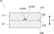
- FIG. 4 is a sectional view taken along line 4-4 in FIG.
- FIG. 5 is a sectional view taken along line 5-5 in FIG.
- FIG. 6 is a sectional view taken along line 6-6 in FIG.
- FIG. 1 is a cross-sectional view illustrating a schematic configuration of the mixing apparatus 10.
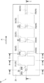
- the chip 12 shown in FIG. 1 is the chip 12 cut along line 1-1 shown in FIG.
- the mixing apparatus 10 includes a chip 12, an irradiation unit 60 (an example of a heating unit), and a moving mechanism 70.
- the fluid and the object to be mixed and the specific configuration of each unit (chip 12, irradiation unit 60, and moving mechanism 70) of the mixing apparatus 10 will be described.
- a fluid that can be mixed with an object to be mixed is used.
- a fluid that reacts with the mixing target or a fluid that contains a substance that reacts with the mixing target for example, a liquid is used.
- a sample liquid containing a sample is used.
- a liquid containing cells from which DNA (deoxyribonucleic acid) is released is used.
- a reactant that reacts with a fluid is used.
- a treatment agent that performs a specific treatment by reacting a fluid is used.
- a surfactant that liberates DNA from cells contained in the sample liquid is used.
- FIG. 2 is an exploded perspective view showing a schematic configuration of the chip 12.
- FIG. 3 is a plan view showing a schematic configuration of the chip 12.
- the chip 12 shown in FIGS. 1, 2, and 3 is a container that contains a liquid and a mixing target and mixes the liquid and the mixing target.
- the chip 12 includes a first substrate 21, a second substrate 22, a plurality of mixing chambers 30, an inflow path 25, and a plurality of flow paths.
- a passage 40 and a plurality of valves 50 are provided.
- a specific configuration of each part of the chip 12 (the first substrate 21, the second substrate 22, the plurality of mixing chambers 30, the inflow channel 25, the plurality of channels 40, and the plurality of valves 50) will be described.
- the first substrate 21 is an example of a forming member in which a flow path is formed and can transmit light. Specifically, a transparent member is used as the first substrate 21. Examples of the material of the first substrate 21 include a resin material and glass.
- the second substrate 22 does not need a function of transmitting light. Accordingly, for example, an opaque member is used as the second substrate 22. A transparent member may be used as the second substrate 22.
- the first substrate 21 and the second substrate 22 are each formed in a rectangular plate shape as an example.
- the first substrate 21 has an upper surface 21A as a surface on one side in the thickness direction and a lower surface 21B as a surface on the other side in the thickness direction.
- the second substrate 22 has an upper surface 22A as a surface on one side in the thickness direction and a lower surface 22B as a surface on the other side in the thickness direction.
- the lower surface 21B of the first substrate 21 and the upper surface 22A of the second substrate 22 are joined.
- the thickness direction of the first substrate 21 and the second substrate 22 is the T direction in FIG.
- the mixing chamber 31 is an example of a first storage unit that stores a fluid.
- the mixing chamber 32 is an example of a second storage unit that stores a mixing target to be mixed with a fluid.
- the mixing chambers 31 to 34 are each configured by a storage space in which the fluid formed in the first substrate 21 can be stored.
- the accommodation space is formed on the lower surface 21B of the first substrate 21 as follows. That is, a recess is formed in the lower surface 21B of the first substrate 21, and a lower side (second substrate 22 side) opening in the recess is closed by the upper surface 22A of the second substrate 22, thereby forming an accommodation space.
- ing. 4 is a cross-sectional view taken along line 4-4 in FIG.
- the mixing chambers 31, 32, 33, and 34 are arranged in this order along the direction orthogonal to the thickness direction (the direction of arrow A in FIGS. 1, 2, and 3). In each of the mixing chambers 31, 32, 33, and 34, a mixing object to be mixed with a fluid is accommodated in advance.
- the inflow passage 25 is a passage through which fluid flows into the mixing chamber 31. As shown in FIGS. 2 and 5, the inflow passage 25 has a first passage 25 ⁇ / b> A and a second passage 25 ⁇ / b> B.
- the first path 25A includes a hole (specifically, a circular hole) formed in the first substrate 21 along the thickness direction (the T direction in FIG. 5). 5 is a cross-sectional view taken along line 5-5 in FIG.
- the second path 25B is formed on the lower surface 21B of the first substrate 21 as follows. That is, a groove is formed in the lower surface 21B of the first substrate 21 along the orthogonal direction (arrow A direction), and the lower (second substrate 22 side) opening in the groove is closed by the upper surface 22A of the second substrate 22. As a result, the second path 25B is formed.
- the 2nd path 25B is formed, for example in cross-sectional semicircle shape, as FIG. 5 shows.
- One end (upper end) of the first path 25A opens at the upper surface 21A of the first substrate 21.
- the other end (lower end) of the first path 25A communicates with one end of the second path 25B.
- the other end of the second path 25 ⁇ / b> B communicates with the mixing chamber 31. Thereby, the fluid flows into the mixing chamber 31 through the inflow passage 25, and the fluid is accommodated in the mixing chamber 31.
- the chips 12 are provided with flow paths 41, 42, 43, and 44 (hereinafter may be referred to as flow paths 41 to 44).
- the flow path 41 is an example of a flow path that connects the first storage portion and the second storage portion.
- the channels 41 to 44 are formed on the lower surface 21B of the first substrate 21 as follows. That is, a groove is formed in the lower surface 21B of the first substrate 21 along the orthogonal direction (arrow A direction), and the lower (second substrate 22 side) opening in the groove is closed by the upper surface 22A of the second substrate 22. As a result, each of the flow paths 41 to 44 is formed. As shown in FIG. 6, each of the flow paths 41 to 44 has a semicircular cross section, for example. 6 is a cross-sectional view taken along line 6-6 in FIG.
- the flow path 41 communicates the mixing chamber 31 and the mixing chamber 32. Further, the channel 42 communicates the mixing chamber 32 and the mixing chamber 33. Further, the channel 43 communicates the mixing chamber 33 and the mixing chamber 34.
- the flow path 44 is opposite to the flow path 43 side (the left side in FIGS. 1 and 3) with respect to the mixing chamber 34 (the right side in FIGS. 1 and 3), and one end communicates with the mixing chamber 34.
- the other end of the flow path 44 is opened on the side surface (the right side surface in FIG. 1) of the first substrate 21.
- the fluid stored in the mixing chamber 34 can flow out to the outside of the chip 12 (the right side in FIGS. 1 and 3) through the flow path 44.
- the flow path 44 functions as a passage through which the fluid flows out of the mixing chamber 34.
- valves 51, 52, 53, and 54 are provided in the chip 12.
- the valve 51 is an example of a valve that is provided in the flow path and can change the shape by heating to open the flow path.
- the valves 51 to 54 are provided in the flow paths 41 to 44, respectively.
- the valves 51 to 54 close the flow paths 41 to 44, respectively.
- fluid cannot flow through each of the flow paths 41 to 44. Therefore, the mixing objects previously stored in the mixing chambers 31 to 34 do not flow out of the mixing chambers 31 to 34, and the mixing objects do not mix with each other.
- thermoplastic material for each of the valves 51 to 54, for example, a thermoplastic material is used. That is, as each of the valves 51 to 54, for example, a substance having a property that can be softened and deformed when heated is used.
- thermoplastic materials include general-purpose plastics (polyethylene (PE), polypropylene (PP), polyvinyl chloride (PVC), polyvinylidene chloride, polystyrene (PS), polyvinyl acetate (PVAc), polyurethane (PUR), poly Tetrafluoroethylene (PTFE), ABS resin (acrylonitrile butadiene styrene resin), AS resin, acrylic resin (PMMA)), engineering plastic (polyamide (PA), nylon, polyacetal (POM), polycarbonate (PC), modified polyphenylene ether (M-PPE, modified PPE, PPO), polyester (PEs), polyethylene terephthalate (PET), glass fiber reinforced polyethylene terephthalate (GF-PET), polybutylene Rephthalate (PBT), cyclic polyolefin (COP)), polyphenylene sulfide (PPS), polysulfone (PSF), polyethersulfone (PES), amorphous polyarylate (PAR),
- valves 51 to 54 are solid in an unheated state, that is, at normal temperature (environment temperature at which the chip 12 is handled). That is, each of the valves 51 to 54 has a melting point higher than room temperature.
- each of the valves 51 to 54 has a melting point lower than the temperature at which the specimen contained in the fluid is thermally denatured.
- the temperature for heat denaturation is, for example, 70 ° C. Therefore, a thermoplastic material having a melting point of less than 70 ° C. is used for each of the valves 51 to 54.
- thermoplastic substance include wax, paraffin, wax, soap, fat and the like.
- Each valve 51 to 54 has a melting point higher than the temperature of the fluid in the state accommodated in each mixing chamber 31 to 34. As a result, the valves 51 to 54 do not melt even when the fluid comes into contact therewith.
- Each valve 51 to 54 has a color material that absorbs light.
- a black color material is used.
- the valves 51 to 54 are heated by absorbing light transmitted through the first substrate 21.
- Each of the valves 51 to 54 changes its shape when heated to open the channels 41 to 44.
- the shape change in each of the valves 51 to 54 is a shape change in which the dimension in the thickness direction (T direction in FIG. 1) of the first substrate 21 is reduced. Specifically, the valves 51 to 54 are melted, for example, flow in an orthogonal direction (the direction of arrow A in FIG. 1) and become flat.
- each valve 51 to 54 is irreversible. That is, the valves 51 to 54 do not return to the original state (a state in which the flow paths 41 to 44 are closed). In other words, the valves 51 to 54 maintain the state where the flow paths 41 to 44 are opened.
- valves 51 to 54 open the channels 41 to 44, so that the fluid can flow through the channels 41 to 44.
- the fluid that has flowed into the mixing chamber 31 through the inflow passage 25 can flow to the mixing chamber 32 through the flow path 41.
- the fluid flowing into the mixing chamber 32 can flow to the mixing chamber 33 through the flow path 42.
- the fluid flowing into the mixing chamber 33 can flow to the mixing chamber 34 through the flow path 43.
- the fluid flowing into the mixing chamber 34 can flow out to the outside (upper side) of the chip 12 through the flow path 44.
- the flow direction of the fluid in the chip 12 is an orthogonal direction (the direction of arrow A in FIG. 1).
- the irradiation unit 60 shown in FIG. 1 is an example of an irradiation unit that irradiates light to a valve.
- the irradiation unit 60 is also an example of a heating unit that heats the valve.
- the irradiation unit 60 includes a light source 62 and a lens 64 as a condensing element, as shown in FIG.
- the light source 62 irradiates from the opposite side (upper side) to the second substrate 22 side (lower side) with respect to the first substrate 21 toward the valve 51 (lower side in FIG. 1).
- the light source 62 a semiconductor light source, a discharge lamp, and a halogen lamp are used.
- the semiconductor light source include a light emitting diode (LED) and a laser diode (LD).
- the light source 62 irradiates infrared light as light, for example. Specifically, the light source 62 irradiates infrared light having a wavelength of 20 ⁇ m or less, for example. Preferably, the light source 62 emits infrared light having a wavelength of 2 ⁇ m or less.
- the lens 64 has a function of condensing the light emitted from the light source 62 by the valve 51.
- the output of the light source 62 may be controlled by measuring the temperature of the valve 51 with a temperature sensor.
- the irradiation unit 60 can be moved relative to the chip 12 in the orthogonal direction (the direction of arrow A in FIG. 1) to each irradiation position where the valves 51 to 54 can be irradiated with light. That is, by moving relative to the chip 12 in the orthogonal direction (the direction of arrow A in FIG. 1), the irradiation position of the irradiation unit 60 can be changed to each irradiation position where the valves 51 to 54 can be irradiated with light. Has been.
- the moving mechanism 70 shown in FIG. 1 is an example of a moving mechanism that moves the fluid stored in the first storage portion to the second storage portion.
- the moving mechanism 70 is configured by a support body that supports the chip 12 so as to descend downward from the mixing chamber 31 toward the mixing chamber 34.
- the mixing chamber 32 (an example of the second storage part) is positioned below the mixing chamber 31 (an example of the first storage part), and the mixing room 33 is positioned below the mixing chamber 32 to perform mixing.
- the mixing chamber 34 is located below the chamber 33.
- the fluid moves from the mixing chamber 31 to the mixing chamber 32 by gravity, moves from the mixing chamber 32 to the mixing chamber 33, and moves from the mixing chamber 33 to the mixing chamber 34.
- the moving mechanism 70 moves the fluid using the gravity acting on the fluid.
- the mixing method includes an inflow step, a first opening step, a first moving step, a second opening step, a second moving step, a third opening step, a third moving step, and a fourth opening step. And an outflow process.
- an inflow step in the order of the inflow process, the first release process, the first movement process, the second release process, the second movement process, the third release process, the third movement process, the fourth release process, and the outflow process.
- the first opening process is an example of a first process in which a valve provided in a flow path that communicates the first storage section and the second storage section is heated to change the shape of the valve to open the flow path.
- the irradiation unit 60 heats the valve 51 by irradiating the valve 51 with light, and changes the shape of the valve 51 to open the flow path 41.
- the first movement step is an example of a second step in which the fluid stored in the first storage unit is moved to the second storage unit in which the mixing target is stored.
- the fluid stored in the mixing chamber 31 is moved to the mixing chamber 32 through the flow path 41 opened by the valve 51.
- the fluid is removed from the mixing chamber 31 by gravity by opening the flow path 41 in the chip 12 supported so as to have a downward gradient from the mixing chamber 31 toward the mixing chamber 34. Move to mixing chamber 32. Thereby, the fluid is mixed in the mixing chamber 32 with the mixing object accommodated in the mixing chamber 32.
- the irradiation unit 60 heats the valve 52 by irradiating the valve 52 with light, and changes the shape of the valve 52 to open the flow path 42.
- the fluid stored in the mixing chamber 32 is moved to the mixing chamber 33 through the flow path 42 opened by the valve 52.
- the fluid is removed from the mixing chamber 32 by gravity by opening the flow path 42 in the chip 12 supported so as to have a downward gradient from the mixing chamber 31 toward the mixing chamber 34.
- Move to mixing chamber 33 Thereby, the fluid is mixed in the mixing chamber 33 with the mixing object accommodated in the mixing chamber 33.
- the irradiation unit 60 heats the valve 53 by irradiating the valve 53 with light, and changes the shape of the valve 53 to open the flow path 43.
- the fluid stored in the mixing chamber 33 is moved to the mixing chamber 34 through the flow path 43 opened by the valve 53.
- the fluid is removed from the mixing chamber 33 by gravity by opening the flow path 43 in the chip 12 supported so as to have a downward gradient from the mixing chamber 31 toward the mixing chamber 34.
- Move to mixing chamber 34 Thereby, the fluid is mixed in the mixing chamber 34 with the mixing object accommodated in the mixing chamber 34.
- the irradiation unit 60 heats the valve 54 by irradiating the valve 54 with light, and changes the shape of the valve 54 to open the flow path 44.
- the flow path 41 is opened by changing the shape of the valve 51 by heating.
- the fluid stored in the mixing chamber 31 is moved to the mixing chamber 32 through the flow path 41 opened by the valve 51.
- the mechanical operation refers to, for example, applying an external force to the valve 51 to perform operations such as pushing, pulling, and turning.
- the valve 51 is heated by irradiating the valve 51 with light, and the shape of the valve 51 is changed to open the flow path 41. Therefore, the valve 51 can be heated without contact with the chip 12. As a result, it can suppress that a foreign material mixes into the fluid.
- valve 51 since the valve 51 has a color material that absorbs light, the valve 51 can be heated in a short time after the light irradiation is started. As a result, the channel 41 can be opened in a short time after the start of light irradiation.
- the flow path 41 can be opened by softening the valve 51 to a flat state, so that the flow path 41 is opened as compared with the case where the flow path 41 is opened by contracting the valve 51, for example. 41 can be opened widely.
- valve 51 has a melting point lower than the temperature at which the specimen contained in the fluid is thermally denatured. For this reason, the channel 41 can be opened without subjecting the specimen to thermal denaturation.
- the fluid is moved by gravity in each of the flow paths 41 to 44, but is not limited thereto.
- the structure which moves a fluid using magnetic force, electrostatic attraction force, pressure, etc. may be sufficient.
- the structure which moves a fluid combining several gravity, magnetic force, electrostatic attraction force, pressure, etc. may be sufficient.
- the flow path 41 is opened by softening the valve 51 to make it flat, but the present invention is not limited to this.
- the valve may be contracted to open the flow path.
- a thermosetting substance is used as the valve.
- the thermosetting substance include phenol resin (PF), epoxy resin (EP), melamine resin (MF), urea resin (urea resin, UF), unsaturated polyester resin (UP), alkyd resin, polyurethane (PUR). ) And thermosetting polyimide (PI).
- these thermosetting substances may be used independently and may be used in combination of 2 or more type.
- valves 51 to 54 are heated by irradiating the valves 51 to 54, and the shapes of the valves 51 to 54 are changed to open the channels 41 to 44. It is not limited to this.
- a configuration in which the valves 51 to 54 are heated using a heater in contact with the chip 12 may be employed.
- each of the valves 51 to 54 has a color material that absorbs light, but is not limited thereto.
- the peripheral portions of the valves 51 to 54 may have a color material that absorbs light. Accordingly, it is sufficient that at least one of the valve and the peripheral portion of the valve has a color material that absorbs light.
- the peripheral portion include a contact portion in contact with the valves 51 to 54 on the first substrate 21 and a contact portion in contact with the valves 51 to 54 on the second substrate 22.
- the mixing chamber 31 is an example of the first storage part
- the mixing chamber 32 is an example of the second storage part
- the flow path 41 is an example of a flow path that connects the first storage part and the second storage part.
- the valve 51 has been described as an example of a valve whose shape can be changed by heating to open the flow path, but is not limited thereto.
- the mixing chamber 32 is an example of a first storage part
- the mixing chamber 33 is an example of a second storage part
- the flow path 42 is an example of a flow path that communicates the first storage part and the second storage part
- ascertain the valve 52 as an example of the valve which a shape changes with heating and can open a flow path.
- the mixing chamber 33 is an example of a first housing part
- the mixing chamber 34 is an example of a second housing part
- the flow path 43 is an example of a flow path that connects the first housing part and the second housing part
- the mixing apparatus 10 can be used as a processing apparatus for polymerase chain reaction.
- the mixing apparatus 10 is configured as follows.
- a surfactant having an action of dissolving the cell membrane is stored in the mixing chamber 31 in advance.
- a cleaning solution for example, 70% ethanol
- cleaning DNA deoxyribonucleic acid
- a reaction solution containing a DNA polymerase and a primer is previously stored in the mixing chamber 33 as a mixing target.
- a preparation liquid for example, a buffer liquid
- sample preparation is previously stored in the mixing chamber 34 as a mixing target.
- the mixing apparatus 10 is used as a polymerase chain reaction processing apparatus, for example, the polymerase chain reaction is processed by the following processing method.
- a sample liquid (an example of a fluid) containing cells as a sample is caused to flow into the mixing chamber 31 through the inflow channel 25. Thereby, the sample liquid is accommodated in the mixing chamber 31.
- the specimen liquid stored in the mixing chamber 31 is mixed with the surfactant previously stored in the mixing chamber 31 in the mixing chamber 31. This releases DNA from the cell.
- the irradiation unit 60 heats the valve 51 by irradiating the valve 51 with light, and changes the shape of the valve 51 to open the flow path 41.
- DNA is separated using a separation method in which DNA is adsorbed on magnetic particles and the magnetic particles are moved to the mixing chamber 32 by magnetic force, or a separation method in which DNA is separated by a filter.
- the separation methods may be used alone or in combination.
- the DNA separated into the mixing chamber 32 is mixed with the cleaning liquid stored in the mixing chamber 31. Thereby, DNA is washed.
- the irradiation unit 60 heats the valve 52 by irradiating the valve 52 with light, and changes the shape of the valve 52 to open the flow path 42.
- the DNA mixed with the washing liquid is moved to the mixing chamber 33 through the flow path 42 opened by the valve 52. That is, the DNA is separated from the washing solution into the mixing chamber 33. Specifically, DNA is separated using the aforementioned separation method.
- the DNA separated into the mixing chamber 33 is mixed with the reaction solution stored in the mixing chamber 33. Then, the polymerase chain reaction is performed by repeatedly heating and cooling the DNA mixed with the reaction solution.
- the irradiation unit 60 heats the valve 53 by irradiating the valve 53 with light, and changes the shape of the valve 53 to open the flow path 43.
- the reaction solution mixed with DNA is moved to the mixing chamber 34 through the flow path 43 opened by the valve 53. Thereby, a reaction liquid is mixed with a preparation liquid and sample preparation is performed.
- the irradiation unit 60 heats the valve 54 by irradiating the valve 54 with light, and changes the shape of the valve 54 to open the flow path 44.
Landscapes
- Chemical & Material Sciences (AREA)
- General Engineering & Computer Science (AREA)
- Engineering & Computer Science (AREA)
- Health & Medical Sciences (AREA)
- Chemical Kinetics & Catalysis (AREA)
- Mechanical Engineering (AREA)
- Dispersion Chemistry (AREA)
- Analytical Chemistry (AREA)
- General Health & Medical Sciences (AREA)
- Immunology (AREA)
- Physics & Mathematics (AREA)
- Life Sciences & Earth Sciences (AREA)
- Biochemistry (AREA)
- General Physics & Mathematics (AREA)
- Pathology (AREA)
- Clinical Laboratory Science (AREA)
- Hematology (AREA)
- Toxicology (AREA)
- Automatic Analysis And Handling Materials Therefor (AREA)
- Accessories For Mixers (AREA)
- Physical Or Chemical Processes And Apparatus (AREA)
- Apparatus Associated With Microorganisms And Enzymes (AREA)
Abstract
La présente invention concerne un embout comprenant une première unité de réception pour recevoir un fluide, une seconde unité de réception pour recevoir un matériau à mélanger qui doit être mélangé avec le fluide, un canal à travers lequel la première unité de réception et la seconde unité de réception communiquent, et une vanne disposée dans le canal et qui peut ouvrir le canal en changeant de forme par chauffage.
Priority Applications (2)
| Application Number | Priority Date | Filing Date | Title |
|---|---|---|---|
| JP2020509597A JP7123125B2 (ja) | 2018-03-30 | 2018-10-31 | チップ、混合装置及び混合方法 |
| US17/035,220 US11448332B2 (en) | 2018-03-30 | 2020-09-28 | Chip, mixing device, and mixing method |
Applications Claiming Priority (2)
| Application Number | Priority Date | Filing Date | Title |
|---|---|---|---|
| JP2018066536 | 2018-03-30 | ||
| JP2018-066536 | 2018-03-30 |
Related Child Applications (1)
| Application Number | Title | Priority Date | Filing Date |
|---|---|---|---|
| US17/035,220 Continuation US11448332B2 (en) | 2018-03-30 | 2020-09-28 | Chip, mixing device, and mixing method |
Publications (1)
| Publication Number | Publication Date |
|---|---|
| WO2019187294A1 true WO2019187294A1 (fr) | 2019-10-03 |
Family
ID=68061001
Family Applications (1)
| Application Number | Title | Priority Date | Filing Date |
|---|---|---|---|
| PCT/JP2018/040587 Ceased WO2019187294A1 (fr) | 2018-03-30 | 2018-10-31 | Embout, dispositif et procédé de mélange |
Country Status (3)
| Country | Link |
|---|---|
| US (1) | US11448332B2 (fr) |
| JP (1) | JP7123125B2 (fr) |
| WO (1) | WO2019187294A1 (fr) |
Cited By (2)
| Publication number | Priority date | Publication date | Assignee | Title |
|---|---|---|---|---|
| WO2021059836A1 (fr) * | 2019-09-27 | 2021-04-01 | 富士フイルム株式会社 | Récipient et kit d'inspection |
| JP2023524069A (ja) * | 2020-04-29 | 2023-06-08 | アボット・ラボラトリーズ | 試料分析のためのシステム及び方法 |
Citations (4)
| Publication number | Priority date | Publication date | Assignee | Title |
|---|---|---|---|---|
| US20070092409A1 (en) * | 2005-10-21 | 2007-04-26 | Beatty Christopher C | Reconfigurable valve using optically active material |
| JP2008062232A (ja) * | 2006-09-05 | 2008-03-21 | Samsung Electronics Co Ltd | 熱活性ユニットを備えた遠心力基盤の微細流動装置、これを備える微細流動システム及び前記微細流動システムの駆動方法 |
| JP2009250830A (ja) * | 2008-04-08 | 2009-10-29 | Aloka Co Ltd | マイクロチップ |
| WO2016136551A1 (fr) * | 2015-02-25 | 2016-09-01 | 国立大学法人東京大学 | Vanne, dispositif à fluide et procédé de production de dispositif à fluide |
Family Cites Families (24)
| Publication number | Priority date | Publication date | Assignee | Title |
|---|---|---|---|---|
| FI981432A7 (fi) * | 1998-06-22 | 2000-01-14 | Niilo Kaartinen | Jäähana |
| JP2001165939A (ja) * | 1999-12-10 | 2001-06-22 | Asahi Kasei Corp | キャピラリー分析装置 |
| US6679279B1 (en) * | 2002-07-10 | 2004-01-20 | Motorola, Inc. | Fluidic valve having a bi-phase valve element |
| JP3913189B2 (ja) | 2003-04-17 | 2007-05-09 | キヤノン株式会社 | 微細粒子分離回収装置 |
| KR100668335B1 (ko) * | 2005-04-02 | 2007-01-12 | 삼성전자주식회사 | 자성 왁스 플러그를 구비한 마이크로 밸브 및 자성 왁스를이용한 유동 제어 방법 |
| US7998433B2 (en) * | 2006-04-04 | 2011-08-16 | Samsung Electronics Co., Ltd. | Valve unit and apparatus having the same |
| US8464760B2 (en) * | 2006-08-16 | 2013-06-18 | Samsung Electronic Co., Ltd. | Valve unit, reaction apparatus with the same, and method of forming valve in channel |
| KR100818274B1 (ko) * | 2006-09-05 | 2008-04-01 | 삼성전자주식회사 | 미세유동 시스템 제어장치 및 그 방법, 및 미세유동 시스템 |
| KR100846501B1 (ko) * | 2006-11-09 | 2008-07-17 | 삼성전자주식회사 | 밸브 유닛 및 이를 구비한 유체 처리 장치 |
| KR20080073934A (ko) * | 2007-02-07 | 2008-08-12 | 삼성전자주식회사 | 밸브 충전물 및 이를 구비한 밸브 유닛 |
| KR101258434B1 (ko) * | 2007-05-03 | 2013-05-02 | 삼성전자주식회사 | 미세유동 시스템 및,이의 제조방법 |
| US7980272B2 (en) * | 2007-06-21 | 2011-07-19 | Samsung Electronics Co., Ltd. | Microfluidic valve, method of manufacturing the same, and microfluidic device comprising the microfluidic valve |
| KR100919400B1 (ko) * | 2008-04-07 | 2009-09-29 | 삼성전자주식회사 | 미세유동장치 및 그 제조방법 |
| KR100960066B1 (ko) * | 2008-05-14 | 2010-05-31 | 삼성전자주식회사 | 동결건조시약이 저장된 미세유동장치 및 이를 이용한시료분석방법 |
| EP2145684A3 (fr) * | 2008-07-14 | 2013-06-26 | Samsung Electronics Co., Ltd. | Dispositif microfluidique, procédé d'analyse d'échantillons l'utilisant, et procédé de mesure du rapport de dilution |
| KR20100023538A (ko) * | 2008-08-22 | 2010-03-04 | 삼성전자주식회사 | 고상 시약의 제조방법 및 고상 시약을 수용하는 미세유동장치 |
| KR101099495B1 (ko) * | 2008-10-14 | 2011-12-28 | 삼성전자주식회사 | 원심력 기반의 미세유동장치, 이의 제조 방법 및 이를 이용한 시료분석방법 |
| KR101157177B1 (ko) * | 2008-11-27 | 2012-06-20 | 삼성전자주식회사 | 표적 물질 처리 시스템 및 방법 |
| KR101578149B1 (ko) * | 2009-01-29 | 2015-12-17 | 삼성전자주식회사 | 미세유체 제어용 밸브 유닛, 및 이의 제조방법 |
| TWI421495B (zh) * | 2009-10-30 | 2014-01-01 | Univ Nat Cheng Kung | 微流體晶片 |
| KR20110056168A (ko) * | 2009-11-20 | 2011-05-26 | 삼성전자주식회사 | 미세유동장치, 광조사장치 및 이를 포함하는 미세유동시스템과 그 구동방법 |
| EP2837866A4 (fr) * | 2012-04-12 | 2016-01-27 | Univ Tokyo | Soupape, dispositif microfluidique, microstructure, siège de soupape, procédé de fabrication de siège de soupape, et procédé de fabrication de dispositif microfluidique |
| US9995411B1 (en) * | 2014-07-16 | 2018-06-12 | National Technology & Engineering Solutions Of Sandia, Llc | High-temperature, adhesive-based microvalves and uses thereof |
| EP3348886B1 (fr) * | 2017-01-13 | 2019-11-27 | Consejo Superior De Investigaciones Cientificas | Soupape microfluidique |
-
2018
- 2018-10-31 WO PCT/JP2018/040587 patent/WO2019187294A1/fr not_active Ceased
- 2018-10-31 JP JP2020509597A patent/JP7123125B2/ja active Active
-
2020
- 2020-09-28 US US17/035,220 patent/US11448332B2/en active Active
Patent Citations (4)
| Publication number | Priority date | Publication date | Assignee | Title |
|---|---|---|---|---|
| US20070092409A1 (en) * | 2005-10-21 | 2007-04-26 | Beatty Christopher C | Reconfigurable valve using optically active material |
| JP2008062232A (ja) * | 2006-09-05 | 2008-03-21 | Samsung Electronics Co Ltd | 熱活性ユニットを備えた遠心力基盤の微細流動装置、これを備える微細流動システム及び前記微細流動システムの駆動方法 |
| JP2009250830A (ja) * | 2008-04-08 | 2009-10-29 | Aloka Co Ltd | マイクロチップ |
| WO2016136551A1 (fr) * | 2015-02-25 | 2016-09-01 | 国立大学法人東京大学 | Vanne, dispositif à fluide et procédé de production de dispositif à fluide |
Cited By (4)
| Publication number | Priority date | Publication date | Assignee | Title |
|---|---|---|---|---|
| WO2021059836A1 (fr) * | 2019-09-27 | 2021-04-01 | 富士フイルム株式会社 | Récipient et kit d'inspection |
| US12521718B2 (en) | 2019-09-27 | 2026-01-13 | Fujifilm Corporation | Container and test kit |
| JP2023524069A (ja) * | 2020-04-29 | 2023-06-08 | アボット・ラボラトリーズ | 試料分析のためのシステム及び方法 |
| JP7785691B2 (ja) | 2020-04-29 | 2025-12-15 | アボット・ラボラトリーズ | 試料分析のためのシステム及び方法 |
Also Published As
| Publication number | Publication date |
|---|---|
| US20210010606A1 (en) | 2021-01-14 |
| US11448332B2 (en) | 2022-09-20 |
| JPWO2019187294A1 (ja) | 2021-04-08 |
| JP7123125B2 (ja) | 2022-08-22 |
Similar Documents
| Publication | Publication Date | Title |
|---|---|---|
| US7988915B2 (en) | Microfluidic device using microfluidic chip and microfluidic device using biomolecule microarray chip | |
| US9101935B2 (en) | Microfluidic apparatus and control method thereof | |
| CN102597786B (zh) | 阀单元、具有该阀单元的微流体装置和驱动阀单元的方法 | |
| AU2013204955B2 (en) | Systems and devices for analysis of samples | |
| JP5661918B2 (ja) | 2個の熱ブロックを含むpcr装置 | |
| KR102070469B1 (ko) | 미세유체 분석 어셈블리 및 제조방법 | |
| KR101258434B1 (ko) | 미세유동 시스템 및,이의 제조방법 | |
| EP2324924B1 (fr) | Système microfluidique | |
| KR101256474B1 (ko) | 미세유동 소자와 그 제조 방법 및 이를 이용한 검체 검출 장치 및 방법 | |
| WO2006092959A1 (fr) | Microcanal et puce pour microfluide | |
| US20080193336A1 (en) | Centrifugal force based microfluidic device for dilution and microfluidic system including the same | |
| US20080058192A1 (en) | Centrifugal force based microfluidic device having thermal activation unit, microfluidic system including the same and method of operating the microfluidic system | |
| KR102336308B1 (ko) | 반복 슬라이딩 구동 수단을 구비하는 pcr 장치 및 이를 이용하는 pcr 방법 | |
| US20160038939A1 (en) | Microfluidic device | |
| US11448332B2 (en) | Chip, mixing device, and mixing method | |
| US10919035B2 (en) | Microchip, analysis apparatus, and analysis method | |
| US20120261026A1 (en) | Microfluidic device | |
| JP7234393B2 (ja) | 容器および検査キット | |
| KR101835073B1 (ko) | 히터 유닛이 반복 배치된 열 블록을 포함하는 플루이딕 pcr 칩 및 이를 포함하는 pcr 장치 | |
| CN102004145A (zh) | 盘型微流器件以及血液测试装置 | |
| KR20120139205A (ko) | 히터 유닛이 반복 배치된 열 블록을 포함하는 플루이딕 pcr 장치 | |
| WO2009131043A1 (fr) | Micropuce | |
| WO2016143278A1 (fr) | Micropuce, appareil d'analyse et procédé d'analyse | |
| US20130209329A1 (en) | Microchip | |
| US12551885B2 (en) | Storage of corrosive materials on a fiber-based fluidic device and related methods thereof |
Legal Events
| Date | Code | Title | Description |
|---|---|---|---|
| 121 | Ep: the epo has been informed by wipo that ep was designated in this application |
Ref document number: 18911444 Country of ref document: EP Kind code of ref document: A1 |
|
| ENP | Entry into the national phase |
Ref document number: 2020509597 Country of ref document: JP Kind code of ref document: A |
|
| 122 | Ep: pct application non-entry in european phase |
Ref document number: 18911444 Country of ref document: EP Kind code of ref document: A1 |