WO2019187355A1 - Dispositif d'élimination les sédiments/matières flottantes dans l'eau et sur la surface de l'eau - Google Patents
Dispositif d'élimination les sédiments/matières flottantes dans l'eau et sur la surface de l'eau Download PDFInfo
- Publication number
- WO2019187355A1 WO2019187355A1 PCT/JP2018/044671 JP2018044671W WO2019187355A1 WO 2019187355 A1 WO2019187355 A1 WO 2019187355A1 JP 2018044671 W JP2018044671 W JP 2018044671W WO 2019187355 A1 WO2019187355 A1 WO 2019187355A1
- Authority
- WO
- WIPO (PCT)
- Prior art keywords
- hood
- water
- drain pipe
- water surface
- sediment
- Prior art date
- Legal status (The legal status is an assumption and is not a legal conclusion. Google has not performed a legal analysis and makes no representation as to the accuracy of the status listed.)
- Ceased
Links
- WFFORRREWUAYIL-UHFFFAOYSA-N CCC(C)(CC)C1CCCC1 Chemical compound CCC(C)(CC)C1CCCC1 WFFORRREWUAYIL-UHFFFAOYSA-N 0.000 description 1
- 0 [Cn]CCC1CCCC1 Chemical compound [Cn]CCC1CCCC1 0.000 description 1
Images












Classifications
-
- B—PERFORMING OPERATIONS; TRANSPORTING
- B01—PHYSICAL OR CHEMICAL PROCESSES OR APPARATUS IN GENERAL
- B01D—SEPARATION
- B01D21/00—Separation of suspended solid particles from liquids by sedimentation
- B01D21/02—Settling tanks with single outlets for the separated liquid
-
- B—PERFORMING OPERATIONS; TRANSPORTING
- B01—PHYSICAL OR CHEMICAL PROCESSES OR APPARATUS IN GENERAL
- B01D—SEPARATION
- B01D21/00—Separation of suspended solid particles from liquids by sedimentation
- B01D21/24—Feed or discharge mechanisms for settling tanks
-
- C—CHEMISTRY; METALLURGY
- C02—TREATMENT OF WATER, WASTE WATER, SEWAGE, OR SLUDGE
- C02F—TREATMENT OF WATER, WASTE WATER, SEWAGE, OR SLUDGE
- C02F1/00—Treatment of water, waste water, or sewage
- C02F1/40—Devices for separating or removing fatty or oily substances or similar floating material
Definitions
- the present invention relates to an apparatus for effectively removing sediment and suspended matters from the water and the water surface in a water purification treatment facility.
- Patent Documents 1 and 2 In conventional water purification treatment, many sedimentation basins have a mechanism to settle turbidity and the like and transport the supernatant water to the filtration basin using a water collection trough (Patent Documents 1 and 2).
- the present invention provides a device for removing sediment and suspended matter from the water and water surface that can overcome such disadvantages of conventional water treatment facilities and effectively remove suspended matter that cannot be completely settled in a sedimentation basin. Is the issue.
- the present invention solves the above-mentioned problem, is installed in the water of a sedimentation basin, has a space where the lower part is opened and contains water, and at least a part of the inner wall surface is on the lower side.
- a device for removing sediment and suspended matters from the water and the water surface comprising a hood formed so as to incline toward the surface, and a drain pipe for draining water taken into the hood at or near the top of the hood It is.
- the hood is provided with a discharge hole at the top and an intake opening that opens downward at the bottom, and a ceiling wall that extends while converging from the periphery of the intake opening to the discharge hole,
- An apparatus for removing sediment / floating matter from the water and the water surface comprising a drain pipe connected upward from the discharge hole so as to communicate with a space in the hood.
- the hood has a pair of top walls continuously provided on the upper side so as to extend toward the lower side while being separated from each other, and the left and right sides of the top wall are provided with the continuous Drainage which has a side wall formed to a predetermined height from the portion, extends along the continuous portion, has an opening formed in the peripheral wall thereof, and both end portions thereof penetrate the side wall and protrude out of the hood.
- the underwater and water surface sediment / float removal apparatus is a float having a small specific gravity by a hood having a top wall formed so that at least a part of its inner wall surface is inclined downward. Gathers in the direction of the top of the top wall and efficiently guides into the drain pipe provided at the top or near the top to effectively remove the suspended matter in the water and the water surface that does not settle. Furthermore, the upper surface of the top wall serves as an inclined plate, and sedimentation of flocs and the like can be promoted. *
- A The perspective view of the food
- B The perspective view of the food
- A Sectional drawing of the food
- B Sectional drawing of the food
- C Sectional drawing of the food
- D Sectional drawing of the food
- FIG. 4 is a cross-sectional view taken along line AA ′ of a different embodiment in which fins are provided in the flow path assembly of the apparatus for removing sediment and suspended solids on the water and water surface according to the present invention, and FIG. (A) Sectional drawing of the fin provided in the side wall of the underwater and water surface sediment / floating matter removal apparatus which concerns on this invention. (B) The same top view.
- (B) The figure which represents typically about the installation example from which the underwater and the sediment / floating matter removal apparatus of a water surface differ.
- (C) The figure which represents typically about the different installation example of the sediment / floating matter removal apparatus in water and a water surface. Sectional drawing of what has arrange
- A The front view of the food
- B The side view.
- C Middle vertical partial cross-sectional view of the same side surface.
- D The front center longitudinal cross-sectional view.
- A The perspective view of the food
- A The side view of the food
- B The side view of the food
- A The fragmentary sectional view of the food
- B The fragmentary sectional view of the food
- A Sectional drawing of what provided the flow-path aggregate
- B Sectional drawing of the different embodiment which provided the flow-path aggregate
- A The figure which represents typically about the example of installation of the sediment / floating matter removal apparatus in the water which concerns on this invention, and a water surface.
- (B) The figure which represents typically about the installation example from which the underwater and the sediment / floating matter removal apparatus of a water surface differ.
- (C) The figure which represents typically about the different installation example of the sediment / floating matter removal apparatus in water and a water surface.
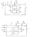
- (A) The figure which represents typically what installed the several food
- (B) The figure which represents typically what has arrange
- (A) The figure which represents typically what was installed so that the top wall of a food
- (B) The figure which represents typically what was installed so that the top wall of a hood may face with respect to the flow of water by the installation example of the sediment / floating matter removal apparatus of water and a water surface.
- the underwater and water surface sediment / float removal device is installed in the water of a settling basin, has a space for containing water therein, is opened at the bottom, and is at least a part of its inner wall surface. Is provided with a hood having a top wall formed so as to incline toward the lower side, and a drain pipe for draining water taken into the hood is provided at or near the top.
- a drain pipe for draining water taken into the hood is provided at or near the top.
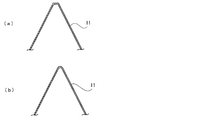
- FIG. 1 (a) is a perspective view of the apparatus for removing sediment / floating matter from the water and the water surface according to the present invention
- FIG. 1 (b) is a sectional view thereof.
- the hood 1 that constitutes the underwater and water surface floating substance removing device according to the present invention has a space 101 for containing water therein, the lower part is open, and the inner wall surface 114 faces downward from the top to the lower part.
- the ceiling wall 11 is formed so as to be inclined.
- a discharge hole 111 is formed at the top of the ceiling wall 11, and an intake port 112 having an opening area larger than that of the discharge hole 111 is formed below the top wall 11, and the peripheral hole 113 of the intake port 112 leads to the discharge hole 111.
- the drainage pipe 2 is connected to the discharge hole 111 so as to extend upward.
- the drain pipe 2 communicates with the space 101 in the hood 1 and discharges water and suspended matters in the space 101 to the outside of the sedimentation basin through the drain pipe 2.
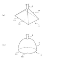
- the outer shape of the top wall 11 is formed in a substantially truncated cone shape, but a part or all of the inner wall surface 114 of the top wall 11 is formed so as to be inclined downward.
- the outer shape is not limited to this, and may be a truncated pyramid shape as shown in FIG. 3A or a dome shape as shown in FIG. In this way, the inner wall surface 114 of the hood 1 is formed so as to be inclined downward and converges from the peripheral edge 113 of the intake port 112 toward the discharge hole 111, thereby being taken into the space 101 from the intake port 112.
- the floated material having a small specific gravity is sucked toward the discharge hole 111 in the upper center of the top wall 11 and is effectively guided into the drain pipe 2. Furthermore, by making the top wall 11 into a truncated cone shape, a truncated pyramid shape, or a dome shape, the upper surface of the top wall 11 serves as an inclined plate, and sedimentation of floating substances such as flocks can be promoted.
- the inclination angle of the top wall 11 is not particularly limited, and the effect is obtained even when the inclination is 1 degree with respect to the horizontal.
- the top wall 11 continuously converges from the peripheral edge 113 to the connecting portion with the drain pipe 2.
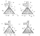
- the shape of the top wall 11 is not limited to this, and for example, FIG. As in (a), the periphery of the connecting portion with the drain pipe 2 may be the top surface 18 extending in the horizontal direction, or may be formed so as to converge from the peripheral edge 113 to the edge of the top surface 18. .
- a vertical surface 19 that is not inclined may be formed on a part of the top wall 11.
- the vertical surface 19 side can easily reach the drain pipe 2 without being disturbed by the hood 1.
- the installation and maintenance work of the device in water becomes easy.
- the top wall 11 includes a part that inclines in reverse so that the inner wall surface 114 faces upward rather than downward.
- the drainage pipe 2 connected to the discharge hole 111 and rising in the vertical direction is branched into a drainage pipe 21 extending in the horizontal direction and an air vent pipe 24 rising in the vertical direction.
- a drain valve 22 is provided in front of the discharge port 23 at the end of the drain pipe 21, and an air vent valve 25 is provided in front of the exhaust port 26 at the end of the air vent pipe 24.
- Such an air vent pipe 24 may be provided as necessary.
- the air vent pipe 24 is not provided, only the drain pipe 21 that continues from the drain pipe 2 in the lateral direction may be provided.
- the air vent pipe 24 as in this embodiment, the air that has entered the drain pipe 2 from the hood 1 can be effectively vented, and water can be smoothly drained from the drain pipe 21.
- a part of the drain pipe 21 may have a bellows structure, and the position of the hood 1 can be easily adjusted when the water level of the sedimentation basin 3 is changed by making the drain pipe 21 a bellows structure in this way.
- the number of drain pipes 2 is not limited to one for each hood 1, and a plurality of drain pipes may be provided as necessary.
- the inlet hood 1 is provided in the middle of the top wall 11 in addition to the drain pipe 2 connected to the discharge hole 111 at the top of the hood 1.
- a drainage pipe 2 ′ connected to the discharge hole 111 ′ may be separately provided.
- two such drain pipes 2 ' are added separately, but the number is not limited to this.
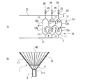
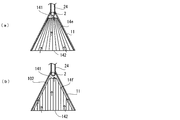
- the space 101 in the hood 1 may be a complete cavity as shown in FIG. 1 (b), but if necessary, flow path assemblies 14a and 14b as shown in FIGS. 2 (a) and 2 (b) may be used. It may be provided.
- the flow path assemblies 14 a and 14 b divide the space 101 in the hood 1 in the horizontal direction, the upper opening 141 toward the discharge hole 111 of the hood 1, and the lower opening 142 as the intake opening of the hood 1.
- the hood 1 is provided so as to extend in the vertical direction so as to face the 112 side.
- the 2A is formed as a bundle of a plurality of thin tubes.
- Each of these thin tubes is formed so that the diameter becomes narrower from the lower end to the upper end, and in the central portion of the hood 1, in a substantially vertical direction, and as the top wall 11 is approached, the top wall 11 is inclined. They are bundled at an appropriate angle along each other. Thereby, the overall shape when the thin tubes are bundled becomes a substantially frustum shape similar to the shape of the space 101 formed by the top wall 11 of the hood 1.
- the upper opening 141 of the flow path assembly 14 a is located below the discharge hole 111 of the hood 1, and the lower opening 142 is provided so as to be located at the intake port 112 of the hood 1. It is not limited to this.
- the flow path assembly 14 a is attached to the hood 1 by fixing the peripheral wall of the thin tube located on the outermost peripheral side to the inner wall surface 114 of the hood 1.
- the flow path assembly 14b of FIG. 2 (b) is formed such that individual thin tubes have the same diameter from the upper end portion to the lower end portion and are all bundled so as to extend in the vertical direction.
- the length of the narrow tube is long at the center side along the inclination of the wall 11 and is shortened toward the end.
- the overall shape when the thin tubes are bundled becomes a substantially frustum shape similar to the shape of the space 101 formed by the top wall 11 of the hood 1.
- the flow path assembly 14 b is provided slightly lower than the top wall 11 so as to form a gap 102 between the inner wall surface 114 of the hood 1.
- the flow path assembly 14 b is attached by fixing the peripheral wall of the thin tube located on the outermost side and the inner wall surface 114 of the hood 1 with a fixing member 143.
- the flow path assemblies 14a and 14b both take in water and suspended matter from the lower opening 142 of the thin tube and discharge them into the hood 1 from the upper opening 141.
- the horizontal cross section of the space 101 in the hood 1 is subdivided by a plurality of thin tubes, and the individual opening area is reduced. It can be demonstrated.
- the flow of water in the hood 1 is arranged in an upward direction so that extra convection such as a lateral flow does not occur, and the suspended matter can be sucked up effectively.
- the flow path assemblies 14a and 14b are formed by bundling a plurality of cylindrical tubules as shown in FIG. 5A, but the cross-sectional shape of each tubule is not limited to a circle.
- a so-called honeycomb structure in which the cross-sectional shape is a square or rectangular thin tube, a regular hexagonal thin tube as shown in FIG. 5B, or other cross-sectional shapes may be used.
- the narrow tubes constituting the channel assemblies 14a and 14b can be formed to have an arbitrary thickness, but in order to maximize the above effects, the inner diameter may be formed in the range of 0.1 mm to 50 mm. preferable. Note that the inner diameters of the individual capillaries do not have to be the same as each other, and may differ depending on the location.
- the interval is not particularly limited.
- the horizontal cross section can be subdivided in the space 101 of the hood 1, it is not limited to an assembly in which thin tubes are bundled, and a plurality of flow paths are divided into partition plates 144 as shown in FIGS. A partition may be formed.
- a block-shaped member 145 may have a plurality of longitudinal hole portions 146 that serve as flow paths.
- the flow passage assembly 14 has a diameter that becomes narrower as it goes from the lower part to the upper part, or that that has the same diameter from the upper part to the lower part.
- the diameter is not limited, and as shown in FIG. 2C, the diameter may be reduced from the upper part to the lower part of the thin tube. Thereby, the flow velocity on the side of the lower opening 142 having a smaller diameter is increased, and the suction effect can be improved.
- the diameter of the upper opening 141 is increased, it is possible to obtain an effect that floating substances and the like are not easily clogged. 2C is fixed to the inner wall 114 of the hood 1 while the individual thin tubes are fixed to each other by rod-like fixing members 143 that do not inhibit the flow of water. Has been.
- a plurality of vertical hole portions 146 are formed in the block-shaped member 145 as a flow passage assembly 14d, and each vertical hole portion 146 goes from the upper part to the lower part. You may form so that a diameter may become thin. This also has the same effect as the embodiment of FIG.
- a side wall 12 may be provided below the top wall 11 of the hood 1 as required.
- the side wall 12 is connected downward from the lower end of the top wall 11, and in the present embodiment, the side wall 12 is suspended from the top wall 11 and the outer shape thereof is formed in a quadrangular prism shape.
- the side wall 12 is not limited to the one that hangs down in the vertical direction, and may be formed so as to be inclined and extended while spreading outward.
- the side wall 12 can be formed at an arbitrary inclination angle, but is preferably provided so as to be inclined or vertical within a range of 45 to 90 degrees with respect to the horizontal.
- the flow path assembly 14 may be provided in the hood 1 as necessary.
- the inside of the top wall 11 has the same structure as that of FIGS. 2 (a) and 2 (b), and the narrow tube formed in the side wall 12 has the same diameter from the top to the bottom. May be bundled so as to extend in the vertical direction, and the entire bundle shape may be provided so as to be similar to the shape of the internal space of the side wall 12.
- the flow path assembly 14 d in FIG. 6D can be attached to the hood 1 by fixing the peripheral wall of the outermost thin tube to the inner wall of the side wall 12.
- the flow path assemblies 14 c and d may be provided not only in the hood 1 and the side wall 12 but also only in the hood 1 or only in the side wall 12. Moreover, when providing in the side wall 12, you may provide only about a part of the height. Furthermore, it goes without saying that the flow path assembly 14 includes a plurality of small chambers partitioned by the partition plate 144 and a block-shaped member 145 having a plurality of vertical hole portions 146 penetrating therethrough.
- fins protruding in the lateral direction may be separately provided inside the flow path assembly 14.
- the flow path assembly 14 in the side wall 12 is defined by a plurality of partition plates 147, and fins 148 are formed on the side walls 12 with respect to the partition plate 147.
- Fins 149 are provided so as to protrude in the horizontal direction.
- the fins 148 are provided so as to protrude from the partition plate 147 standing at the center toward the left and right side walls 12, whereas the fins 149 are extended from the left and right side walls 12 toward the center partition plate 147. Protrusively provided.
- the middle three-stage fins 148 and 149 protrude alternately at different heights, and the uppermost and lowermost fins 148 and 149 face each other at the same height.
- a gap 103 through which water passes is formed while protruding.
- fins 148 are provided so as to protrude in the direction of the left and right side walls 12 with respect to the partition plate 147 provided upright in the center. Further, fins 149 are provided so as to protrude toward the central partition plate 147 with respect to the left and right side walls 12. The fins 148 and 149 protrude oppositely at the same height, and a gap 103 through which water passes is formed between them. In addition, it is preferable that the space
- the fins 148 and 149 may be provided not only on the partition plate 147 and the side wall 12 but also on the top wall 11. Further, the fin is not limited to the one protruding in the horizontal direction as shown in FIG. 7 and may be inclined so that the tip side faces downward as shown in FIG. The inclination angle is not particularly limited, but is preferably in the range of 0 to 60 degrees with respect to the horizontal. Furthermore, an opening 104 may be provided between the fins 148 and 149, the partition plate 147, and the side wall 12.
- the shape and size of the opening 104 are not limited, and may be formed in a plurality of holes, for example.
- a blade portion 13 may be provided at the lower portion of the side wall 12 as necessary.
- the blade portion 13 is formed so as to be inclined and extended from the lower end of the side wall 12 to the outside of the hood 1. In this way, by providing the blade portion 13 that is inclined downward and outward at the lower portion of the side wall 12, it is possible to promote the sedimentation of floating substances such as flocks, and further, when the water flows from the lower portion to the upper portion A floating substance can also be effectively taken into the hood 1 by hitting the blade portion 13.
- a flow path assembly 14 in which a plurality of thin tubes are formed in a bundle in the space 101 in the hood 1 may be provided as necessary.
- a pair of blade portions 13 are provided on the opposing side walls 12, but these may be provided only on one of the side walls 12, or provided on all of the front, rear, left and right side walls 12. Further, only a part of the blade portion 13 may be provided for one side wall 12.
- folding pieces 131 folded downward from the blade portion 13 may be provided on the left and right side portions and the lower side portion of the blade portion 13 not connected to the side wall 12.
- the folded piece 131 By providing the folded piece 131, the suspended matter that has entered the lower side of the blade portion 13 can be effectively taken into the hood 1 without escaping from the left or right or below the blade portion 13.
- the hood 1 may be configured as a single hood 1 by assembling a plurality of divided parts.
- three parts including hoods 10a, 10b, and 10c may be provided, and these parts may be assembled to form one hood 1 (FIG. 10b).
- the hood 1 in FIG. 10 is formed by hollowing out the inside of the block body to form a space 101, a drainage channel 103 is formed so as to communicate with the space 101, and the drainage pipe 2 is connected to the outlet of the drainage channel 103. Yes.
- the flow path assemblies 14 provided in the hoods 10a, 10b, and 10c are all fixed to the side wall 12, but the fixing method to the hood 1 is not limited to this.
- the hood 1 of FIG. 10 has shown the aspect at the time of installing so that the intake port 112 side may face up, the direction of the hood 1 is not limited to this.
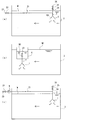
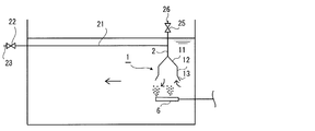
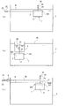
- FIG. 11 schematically shows an installation example of the underwater and water surface sediment / float removal device according to the present invention.
- the arrows indicate the flow of water.
- the drain pipe 21 is provided so that the discharge port 23 is exposed to the outside of the settling basin 3, and in particular, the position where the discharge port 23 is lower than the water surface W in the settling basin 3. It is arranged to be.
- the drain pipe 21 is arranged so that the entire drain pipe 2 including the drain valve 22 as well as the discharge port 23 is positioned lower than the water surface W.
- the discharge port 23 lower than the water surface W
- the water in the sedimentation basin 3 is sucked into the drain pipe 2 from the space 101 in the hood 1 due to the atmospheric pressure applied to the water surface W, and the drain pipe 21.
- the water finally passes through the discharge port 23 through the water. Note that the amount of water taken in from the hood 1 can be appropriately adjusted by the drain valve 22.
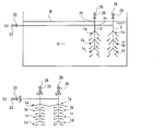
- FIG. 11 (b) schematically shows a sediment / floating matter removing device for draining from the hood 1 to a drain trough 4 provided in the sedimentation basin 3.
- the drainage trough 4 is formed in a bowl shape that can store a predetermined amount of water in its interior, but the water in the sedimentation basin 3 does not flow directly into the interior of the sedimentation basin 3 beyond its upper peripheral wall. is set up.
- the drainage pipe 2 rises as it is from the connecting portion with the hood 1 and is connected to the bottom surface of the drainage trough 4, and the discharge port 23 is provided so as to be exposed in the drainage trough 4.
- the drain pipe 2 of this embodiment is formed as a straight pipe, the air in the drain pipe 2 can be easily removed without providing the air vent pipe 24, and the drainage can be performed smoothly.
- the water in the drainage trough 4 is drained out of the sedimentation basin 3 by a drain pipe or the like (not shown), and the water surface W2 in the drainage trough 4 is always kept lower than the water surface W1 of the sedimentation basin 3. . Since the atmospheric pressure applied to the water surface W1 and the water surface W2 is equal, the water in the sedimentation basin 3 having a high water level is sucked into the hood 1 through the drain pipe 2 so that the water surface W1 and the water surface W2 are balanced. Water is collected into the drainage trough 4 and then drained out of the sedimentation basin 3 by a drain pipe or the like leading to the outside.
- water absorption means by the pump 5 may be provided in the middle of the drain pipe 21, and in this case, the discharge port 23 and the drain pipe 21 may be higher than the water surface W of the sedimentation basin 3.
- the pump 5 can use a general pump such as a vacuum pump or a water absorption pump.
- the water absorbing means is not limited to this, and a water absorbing means using the pump 5 and a water absorbing means utilizing a water level difference may be combined.
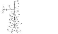
- the underwater and water surface sediment / float removal apparatus of the present invention may include a plurality of hoods 1, and as an example, a plurality of hoods 1 may be provided one above the other.
- a plurality of hoods 1 When a plurality of hoods 1 are stacked one above the other, as shown in FIG. 12, the uppermost hood 1a can be connected by a hood 1b and a drain pipe 27a arranged therebelow.
- the drain pipe 27a is provided so as to hang down from the discharge hole 111a of the upper hood 1a, and is connected to the discharge hole 111b of the hood 1b from above.
- the hood 1b is connected to the hood 1c arranged below by a drain pipe 27b.
- the drain pipes 27a, b are formed with a plurality of slit-shaped openings 271a, b in the vicinity of the discharge holes 111a, b in the hoods 1a, b, respectively, and drains water and suspended matter from the openings 271a, b. It can be taken into the tubes 27a, b.
- the openings 271a and 271b are formed in a slit shape extending in the circumferential direction of the drain pipes 27a and b. However, this may be a slit shape extending in the axial direction, or a slit. It is good also as other shapes, such as circular other than.
- the openings 271a and 271b are not limited in their opening diameters, and may have different opening diameters. That is, if the hood 1 and the drainage pipe 2 are closer to each other, the flow velocity in the hood 1 becomes faster. However, the openings near the drainage pipe 2 at the openings 271a and 271b have a smaller opening diameter. On the contrary, by increasing the diameter of the opening far from the connecting part, the amount of water sucked can be made constant regardless of the position of the opening.
- the water and floating substances taken into the lowermost hood 1c flow into the drain pipe 27b connected to the upper part as they are from the discharge hole 111, but are taken into the hoods 1a and 1b.
- the three hoods 1a, 1b, and 1c are stacked one above the other.
- the number of the hoods 1 is not limited to this, and may be increased or decreased as necessary.
- the intake port 112 of the hood 1 is usually installed so that the intake port 112 faces downward. It may be installed so as to face upward, and further, as shown in FIG. 13, a downward hood 1a and an upward hood 1b may be provided to face each other with a predetermined interval.
- a downward hood 1a and an upward hood 1b may be provided to face each other with a predetermined interval.
- the downward hood 1a and the upward hood 1b are basically arranged at the same position in the horizontal direction so that the centers of the hoods 1a and 1b coincide with each other. The position may be shifted from front to back and from side to side.
- the angles of the hoods 1a and 1b are basically arranged such that the intake ports 112 are parallel to each other, but the angle is not limited to this, and for example, with respect to the intake port 112 of the hood 1a.
- the intake port 112 of the hood 1b may be installed at an angle so as to be inclined.
- the upward hood 1b is installed facing the downward hood 1a.
- the effect of the present invention can be obtained even if the upward hood 1b is installed alone.
- a plurality of hoods 1 may be continuously installed in the front-rear direction with respect to the flow of water. Further, the plurality of hoods 1 may be installed in a grid shape that is continuous in the vertical direction, the horizontal direction, and the oblique direction in plan view. In these cases, a gap may be provided between adjacent hoods 1 or may not be provided. For example, in FIG. 14 (a), three sets of front and rear hoods 1a and 1b facing each other with a predetermined gap are provided in succession.
- the side wall 12a of the hood 1a located on the most upstream side with respect to the flow of water is lengthened, the side wall 12b of the hood 1b is shortened, and conversely, the side wall 12a of the hood 1a behind the hood 1a.
- the length of the side walls 12a and 12b may be staggered in the front and rear directions, such as shortening the length of the side wall 12b of the hood 1b, thereby allowing the water to meander up and down and further enhance the effect of the bypass.
- the three sets of the hood 1a and the hood 1b are continuously installed in the front and rear.
- the number of the hood 1 and the continuous hood is not limited to this and may be appropriately increased or decreased.
- an aeration tube 6 may be appropriately provided below the hood 1 as to the installation method of the underwater and water surface sediment / float removal device according to the present invention.
- the air diffuser 6 By providing the air diffuser 6 below the hood 1 and performing air blowing, the suspended matter rises together with air bubbles and can be efficiently fed into the hood 1. Further, by increasing the amount of air diffused in the air diffuser on the downstream side of the water flow, the bubbles play a role of a kind of air curtain, and the suspended matter is less likely to go downstream than the hood 1, and the hood 1 is more efficient. It becomes possible to take in.
- Nanobubbles and microbubbles have weak buoyancy and may be washed away with water before being taken into the hood. Therefore, a plurality of air diffusing tubes may be provided, and nano bubbles, micro bubbles, normal bubbles, liquids (water, etc.) may be used in combination or in combination.
- the installation of the air diffuser 6 is not limited to the lower side of the hood 1 and may be provided inside the hood 1b as shown in FIG. 14 (a), for example.
- the flow path assembly 14 is provided inside the hood 1, it is preferable to provide the air diffuser 6 between the discharge hole 111 and the flow path assembly 14 as shown in FIG.
- FIG. 16 shows an example of a method for installing the underwater and water surface sediment / float removal device according to the present invention in which a plurality of hoods 1 are stacked one above the other.
- two sets of three hoods 1a, 1b, and 1c are arranged in the front-rear direction with respect to the flow of water.
- These two sets of underwater and water surface sediment / float removal devices are connected in a drain pipe 21, and water and floating matter taken in from any hood 1 are finally discharged from the same outlet 23. .
- only the uppermost hood 1a is provided without a gap, but the hood 1 without a gap is not limited to the uppermost one.
- FIG. 17 As shown in FIG. 3, among the three hoods 1 a, 1 b and 1 c, only the middle hood 1 b may be installed upward.
- the hood 1a and the hood 1b are connected to each other by a drain pipe 27.
- the drain pipe 27 As shown in FIG. 17 (b), the drain pipe 27 is provided in the vicinity of the discharge holes 111a and 111b in the hoods 1a and 1b.
- a plurality of slit-shaped openings 271a and 271b are formed.
- an upward hood 1d may be provided below the hood 1c provided downward.
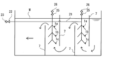
- FIG. 18 shows different installation methods of the underwater and water surface sediment / float removal device according to the present invention in which a plurality of hoods 1 are stacked one above the other.
- two sets of three hoods 1a, 1b, 1c are arranged in the front-rear direction with respect to the flow of water, but before and after the two sets of hoods 1a, 1b, 1c,
- Each barrier 7 is provided.
- the barrier 7 has a gap with the bottom surface of the settling basin 3 on the upstream side of the hoods 1a, 1b, and 1c, and has a gap with the water surface W on the downstream side of the hoods 1a, 1b, and 1c. It is formed as follows.
- the barrier 7 so as to have a gap between the bottom surface or the water surface W before and after the two sets of hoods 1a, 1b, and 1c, the flow of water is below the hoods 1a, 1b, and 1c.
- the suspended matter can be effectively taken into the hood 1 and removed.
- FIGS. 19 (a) to 19 (d) a plurality of the hoods 1 are installed according to FIGS. 19 (a) to 19 (d).
- FIGS. 19 (a) to 19 (d) A specific example will be described.
- the individual thin tubes constituting the flow path assembly 14 in each hood 1 are aligned such that the upper opening 141 on the discharge hole 111 side of the hood 1 has a substantially horizontal height.
- it is not limited to this aspect.
- Fig.19 (a) The thing of Fig.19 (a) is provided with the downward hood 1a and the upward hood 1b facing each other, and between the downward hood 1a and the upward hood 1b, that is, the lower opening 142a of the flow path assembly 14a. Between the lower opening 142b of the tube assembly 14b is a flow path through which water flows. A diffuser pipe 6 may be provided in this flow path, and air bubbles generated by the diffuser pipe 6 raise floating substances contained in the water flowing through the flow path between the hood 1a and the hood 1b. 14a can be efficiently fed into 14a. Such an air diffuser 6 may be provided in the same manner as that shown in FIGS. 19 (b) to 19 (d).
- a barrier 8 having a cross-sectional shape with a substantially V-shape is provided between a downward hood 1a and an upward hood 1b.
- the shape of the barrier 8 is substantially V-shaped, but the shape is not limited to this, and may be a flat plate having a substantially I-shaped cross section.
- the barrier 8 and the air diffuser 6 in combination, separation of suspended matters becomes easier and effective.
- the number, size, and shape of the air diffuser 6 and the barrier 8 are not particularly limited, and the combination method is not limited.
- the water flow can be detoured up and down by changing the height (position) at which the barrier 8 is provided between the upstream side and the downstream side.
- the one shown in FIG. 19 (c) is formed so that the length of the narrow tube constituting the flow path assembly 14a of the downward hood 1a is gradually reduced from the side wall 12a side to the center side of the hood 1a ( As a result, a thin tube is not provided in the central portion), so that the lower opening 142a side is entirely concave.
- the length of the narrow rods constituting the flow passage assembly 14b of the upward hood 1b is formed so as to increase stepwise from the side wall 12b side toward the center side of the hood 1a, thereby the lower opening 142b.
- the side is convex as a whole.
- the flow path of water between the hood 1a and the hood 1b facing each other is formed in an inverted V shape having a low side wall 12 side and a high central portion, and a flow path that meanders in the height direction is formed.
- the water flowing through the flow path meanders up and down to promote detouring, and the floating material can be efficiently fed into the flow path assemblies 14a and 14b.
- the thing of FIG.19 (d) forms the length of the thin tube which comprises the flow path assembly 14a of the downward hood 1a so that it may wave from one side wall 12a side to the other side wall 121a side,
- the lower opening 142a side is uneven.
- the length of the narrow rods constituting the flow passage assembly 14b of the upward hood 1b is also formed in a wavy shape, whereby the lower opening 142b side is uneven. Since the lower opening 142a and the lower opening 142b are out of phase so that the irregularities are opposite to each other, a flow path that meanders in the height direction is formed between the hood 1a and the hood 1b facing each other. As a result, the water meanders up and down and the bypass is promoted, and the floating substance can be efficiently fed into the flow path assemblies 14a and 14b.
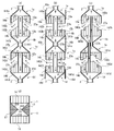
- FIG. 20 (a) is one in which four hoods 1a, b, c, d are stacked one above the other, but are connected to each other by a drain pipe 27.
- the flow path assembly 14a and the flow path assembly 14b are fixed to each other.
- the drain pipe 27a has an upper end and a lower end that are aligned with the upper openings 141a and 141b of the flow path assembly 14a and the flow path assembly 14b.
- hood 1c and the hood 1d below the hood 1c are connected by a drain pipe 27c.
- hood 1 b and the hood 1 c are connected to each other by a drain pipe 27 b connected to the discharge hole 111.
- the flow passage assembly 14a of the hood 1a in FIG. 20 (a) has a lower opening 142a so that the length of the narrow tube gradually decreases from the side wall 12a side toward the drain pipe 27a side of the center of the hood 1a.
- the lower opening 142a is formed in a concave shape as a whole.
- the flow path assembly 14b of the hood 1b is formed with the lower opening 142b obliquely so that the length of the narrow rod gradually increases from the side wall 12b side toward the center side of the hood 1b.
- the opening 142b side is convex as a whole.
- the water flow path between the hood 1a and the hood 1b facing each other is low in the side wall 12 side, and the central part of the hoods 1a and b is high in an inverted V shape.
- the flow is promoted, and the suspended matter can be efficiently fed into the flow path assembly 14.
- the flow path assemblies 14c and 14d of the hood 1c and the hood 1d have the same configuration.
- the flow of water and floating substances in the hoods 1a to d and the drain pipes 27a to 27c in FIG. 20 (a) can be adjusted by a drain valve (not shown) provided in the drain pipe 2. That is, when only the drain valve of the drain pipe 2 connected to the hood 1a is opened, the water flows upward. Further, when only the drain valve of the drain pipe 2 connected to the hood 1d is opened, the water flows downward. When both the upper and lower drainage valves are opened, it flows both upward and downward, but flows more to the larger drainage. In addition to the amount of drainage, there are some that flow upward or downward against the flow due to the specific gravity. That is, the one with a small specific gravity is taken into the upper hoods 1a and 1c, and the one with a large specific gravity that sinks against the upper flow is taken into the lower hoods 1b and 1d. *
- FIG.20 (b) overlaps four food
- the point connected mutually by the drain pipes 27a, b, c is the aspect of FIG. 20 (a). Is the same.
- the narrow tubes constituting the channel assemblies 14a to 14d are formed to have the same length, and all of them are formed flat in the upper openings 141a to 141d and the lower openings 142a to 142d. Is different.
- the hood 1b and the hood 1c in FIG. 20B are provided with a pair of partitions 16b so as to connect the side walls 12b and the side walls 12c.
- the partition 16b is preferably provided as a pair on the opposing surfaces of the side walls 12b and c. In this figure, a pair is provided on the left and right, but a pair may be provided on the front and back.
- the partition 16b between the side wall 12b and the side wall 12c the water flow of this part is prevented and it concentrates on the flow path between the hood 1a and the hood 1b, or between the hood 1c and the hood 1d. be able to.
- hood 1a and the hood 1d may be provided with partitions 16a and 16d so as to extend from the side wall 12a and the side wall 12d to the drain pipe 2 side as necessary. These partitions 16a and 16d can obtain the same effects as the partition 16b.
- portions corresponding to the top wall 11 and the side wall 12 are integrally formed, and the two hoods 1 are joined to each other on the upper surface portion of the block-shaped member 17 as shown in the figure, so that the block-shaped member 17
- the outer surface plays the same role as the partition 16, and the water flow between the hoods 1 can be effectively prevented.
- FIG. 20 (c) four hoods 1a, b, c, and d are stacked, but the drain pipe 27a connecting the hood 1a and the hood 1b is connected to the flow path assembly 14a. It is provided along the narrow tubes at approximately the center of the narrow tubes constituting the flow channel assembly 14b, and the upper part and a part of the center are respectively fixed to the flow channel assembly 14a and the flow channel assembly 14b.
- the drain pipe 27a is formed so that the upper end thereof is aligned with the upper opening 141a, and extends so that a part of the lower side protrudes further downward than the pipe assembly 14b, and the vicinity of the lower end thereof is connected to the hood 1b. It is inserted into a drain pipe 27b that is connected to the hood 1c.
- drain pipe 27c connecting the hood 1c and the hood 1d is provided along the narrow pipes at substantially the center of the narrow pipes constituting the flow path aggregate 14c and the flow path aggregate 14d. And the lower part are fixed to the channel assembly 14c and the channel assembly 14d, respectively.
- the drain pipe 27c is formed so that the lower end thereof is aligned with the upper opening 141d, and extends so that a part of the upper side protrudes further upward from the flow path assembly 14c, and the upper end side thereof is the hood 1b and the hood. It is inserted into a drain pipe 27b that is connected to 1c.
- FIG. 20 (a) to 20 (c) are the four hoods 1a, b, c, and d all stacked in the vertical direction, but not limited to the vertical direction, the whole may be inclined depending on the angle of the pipe. It may be arranged in such a way.
- hood 1 of FIG. 19, FIG. 20 is two or four, it is not limited to these numbers.
- drain pipes 2a, b, c directly connected to the hoods 1a, b, c may be provided individually.
- a drain pipe 2a is directly connected to the hood 1a
- a drain pipe 2b is connected to the hood 1b
- a drain pipe 2c is directly connected to the hood 1c.
- the drain pipe 2b penetrates the hood 1a
- the drain pipe 2c is a hood. It is provided through 1a and 1b.
- FIG. 21B shows an example in which six hoods 1a to 1f are stacked one above the other.
- the hood 1a has a drain pipe 2a
- the hood 1b has a drain pipe 2b
- the hood 1c has a drain pipe.
- a drain pipe 2d is connected to the pipe 2c and the hood 1d
- a drain pipe 2e is directly connected to the hood 1e
- a drain pipe 2f is directly connected to the hood 1f.
- the bundle of drain pipes 2 outside the hood 1 may be stored together in one thick pipe as shown in FIG. 21 (c). At this time, the gaps between the pipes 2a, 2b, and 2c may be appropriately closed as necessary.
- a net 9 may be provided so as to close the gap between the two hoods 1 as shown in FIG.
- FIG. 22 schematically shows the internal structure of a further different embodiment of the hood 1 according to the present invention.
- the hood 1 of this embodiment is characterized in that a water collecting part 29 is provided in the internal space part 101.
- the water collecting portion 229 is formed in a cylindrical shape with both upper and lower ends open, and a plurality of openings 291 are provided on the wall surface.
- this water collection part 29 is connected with the inner pipe part 292 in the upper end part.
- the inner pipe portion 292 is provided in the drain pipe 2 so as to extend to the front of the drain valve (not shown).
- the inner pipe part 292 is fixed to the inner peripheral wall of the drain pipe 2 by four plate-like connecting parts 293 protruding from the outer peripheral surface thereof.
- the suspended matter having a size that can pass through the opening 291 of the water collecting portion 29 is further sucked into the water collecting portion 29 to be It is effectively discharged outside through the part 292.
- suspended solids that cannot pass through the opening 291 are also discharged to the outside through the gap between the drain pipe 2 and the inner pipe 292.
- a partition plate 119 that vertically partitions the space 101 inside the water collecting tank 1 may be provided.
- the partition plate 119 is provided.
- the water collecting portion 29 may be formed in a cylindrical shape that branches into a plurality of portions above and extends into the partitioned space.
- a substantially box-shaped water collecting portion 29 that matches the shape of the hood 1 may be provided in a nested manner.
- the water collecting portion 29 has an opening 291 formed in a slit shape on the front wall surface. Further, the bottom 294 is formed open.
- FIG. 23 to FIG. 34 show still another embodiment of the underwater and water surface sediment / floating matter removal apparatus of the present invention.
- the underwater and surface float removal device of the present embodiment is installed in the water of a settling basin, and has a pair of ceiling walls that are connected to each other on the upper side so as to extend while being separated from each other toward the lower side.
- the left and right sides of the top wall have a hood provided with side walls formed from the connecting portion to a predetermined height, and extend along the connecting portion, and an opening is formed in the peripheral wall.
- the both ends are equipped with the drainage pipe which penetrates the said side wall and protrudes out of a hood.
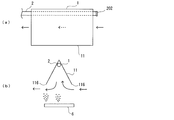
- the hood 1 of the present embodiment has a pair of top walls 11 formed in a flat plate shape connected to each other at their upper sides 115, and from the upper side 115 to the lower side 116. Inclined so as to be separated from each other.
- the ceiling wall 11 is formed in a rectangular shape, but it may have a different shape such as a square or a trapezoid.
- the top wall 11 only needs to be inclined so that at least a part thereof faces downward.
- one of the top walls 11 is inclined.
- the other top wall 11 may be a vertical surface that is not inclined.
- the top wall 11 includes a part that inclines in reverse so that the inner wall surface 114 faces upward rather than downward.
- the left and right side portions 117 of the top wall 11 are provided with a pair of side walls 15 from the connecting portion of the top side portion 115 to a predetermined height so as to close both sides of the space 101 inside the top wall 11.
- the side wall 15 can be provided from the connecting portion of the upper side portion 115 of the top wall 11 to an arbitrary height, and is formed to a minimum height in FIG. Thus, you may provide so that the lower side part 116 of the top wall 11, ie, the both sides of the space 101 of the top wall 11, may be completely plugged up.
- the shape of the side wall 15 is not limited to the triangle as shown in FIG. 23B or FIG. 25A, and other shapes such as an inverted V shape in which the central portion of the base 151 is cut off as shown in FIG. It is good also as a shape.
- a drain pipe 2 is provided in the space 101 in the top wall 11.
- the drain pipe 2 extends in the lateral direction along the connecting portion of the upper side portion 115 of the top wall 11, and both end sides thereof are provided so as to protrude from the side wall 15 to the outside of the hood 1.
- a plurality of slit-like openings 201 are formed in the peripheral wall portion of the portion extending in the space 101 of the top wall 11, and water and floating substances are taken into the drain pipe 2 from the openings 201.
- the opening 201 is formed in a slit shape extending in the circumferential direction of the drain pipe 2, but this may be a slit shape extending in the axial direction, or a circle other than the slit, etc. Other shapes may be used.
- the drain pipe 2 is provided with a discharge port 23 at the end opposite to the end where the cap 202 is attached, and a drain valve 22 is provided in front of the discharge port 23. Furthermore, you may provide the air vent pipe 24 which branches from the middle of the drainage pipe 2 as needed, and stands
- the cap 202 is attached only to one end side of the drainage pipe 2, but it may be attached to both ends of the drainage pipe 2, in which case the drainage pipe 2 is used instead of the air vent pipe 24.
- a drainage pipe that branches off from the middle and rises in the vertical direction may be separately provided.
- the cap 202 is not attached to both ends of the drain pipe 2, and the exhaust port 23 is provided at one end, and the air vent pipe 24 reaching the exhaust port 26 is provided at the other end. Good.
- the top of the hood 1 does not have the opening 118 as shown in FIG. The shape may be completely closed.
- the hood 1 of this embodiment is formed in a substantially triangular shape in a side view, the shape is not limited to a triangular shape, and the upper end portion is flat in the continuous portion of the top wall 11 as shown in FIG. You may form so that it may become an R surface shape which does not have a shape or a corner
- Floating matter having a small specific gravity gathers in the drain pipe 2 provided in the vicinity of the upper connecting portion and can be efficiently taken into the drain pipe 2 from the opening 201.
- the upper surface of the top wall 11 serves as an inclined plate, and the sedimentation of floating substances such as flocs can be promoted.
- the inclination angle of the top wall 11 is not limited, and the effect can be obtained even if the inclination is 1 degree with respect to the horizontal.
- the space 101 in the hood 1 may be a complete cavity as shown in FIG. 23, or a flow path assembly 14 as shown in FIG. 27 may be provided as necessary.
- the flow passage assembly 14 divides the space in the hood 1 in the horizontal direction, and the upper opening 141 is directed to the drain pipe 2 side, and the lower opening 142 is directed vertically so as to face the open side of the hood. Stretch.
- the flow path assembly 14e is formed as a bundle of a plurality of thin tubes.
- the individual rods constituting the flow path assembly 14e are formed so that the diameter becomes narrower from the lower end portion toward the upper end portion, in the central portion of the hood 1 in a substantially vertical direction, and on the top wall 11 As they approach, they are bundled at appropriate angles so as to follow the inclination of the top wall 11.
- the overall shape when the small rods are bundled is similar to the shape of the space 101 formed by the top wall 11 of the hood 1.
- the upper opening 141 of the flow passage assembly 14e is located below the drain pipe 2 and the lower opening 142 is located at the lower end of the hood 1, but these positions are not limited thereto. .
- the flow path assembly 14 e is attached to the hood 1 by fixing the narrow peripheral wall located on the outermost peripheral side to the inside of the top wall 11 of the hood 1.
- the flow path assembly 14f of the embodiment shown in FIG. 27 (b) is bundled so that the fine rods are formed to have the same diameter from the upper end portion to the lower end portion and all extend in the vertical direction.
- the length of each of the narrow rods is formed so as to follow the inclination of the top wall 11.
- the overall shape when the small rods are bundled is similar to the shape of the space 101 formed by the top wall 11 of the hood 1.
- the flow path assembly 14 f is provided lower than the top wall 11 so as to form a gap 102 between the top wall 11 of the hood 1.
- the flow path assembly 14f can be attached by fixing the narrow peripheral walls located on the left and right ends to the inside of the side wall 15 of the hood 1.
- the flow path assemblies 14e and 14f both take in water and suspended matters from the lower opening 142 of the narrow rod and discharge them from the upper opening 141 to the drain pipe 2, but in the case of the flow path assembly 14f, What is discharged into the gap 102 between the top wall 11 moves along the top wall 11 as it is below the drain pipe 2 and is finally taken into the drain pipe 2.
- the horizontal cross section of the hood 1 is subdivided by a plurality of fine ridges, and the individual opening area is reduced, so that the hood 1 can draw the maximum effect. .
- the flow of water in the hood 1 is arranged in an upward direction so that extra convection such as a lateral flow does not occur, and the suspended matter can be sucked up effectively.
- the flow path assemblies 14e and 14f of the present embodiment are formed by bundling a plurality of cylindrical thin tubes
- the cross-sectional shape of each thin tube is not limited to a cylinder, and is shown in FIG.
- the cross-sectional shape may be a square or rectangular thin tube, a so-called honeycomb structure in which regular hexagonal thin tubes are bundled, or other cross-sectional shapes.
- the fine lines constituting the flow path assemblies 14e and 14f can be formed to an arbitrary thickness, but in order to maximize the above effects, the inner diameter should be formed in the range of 0.1 mm to 50 mm. Is preferred. Note that the inner diameters of the individual capillaries do not have to be the same as each other, and may differ depending on the location.
- the interval is not particularly limited.
- the flow passage assembly 14 is not limited to the fine rod assembly, and a plurality of flow passages may be partitioned by a partition plate or a block-shaped member. What penetrated the several vertical hole part used as a flow path is also contained.
- the flow path assembly 14 described above can be provided in any form of the hood 1. However, as shown in FIG. 29A, when the connecting drain pipe 27 is provided in the hood 1. Thus, the flow passage assembly 14 can be provided in other portions while avoiding the drain pipe 27 portion.
- FIG. 28 schematically shows an installation example of the underwater and water surface sediment / float removal device according to the present invention.
- the drain pipe 2 is provided so that the side where the cap portion 202 is not attached is extended so that the discharge port 23 is exposed to the outside of the sedimentation basin 3, and in particular, the discharge port 23 is It arrange
- FIG. The drain pipe 2 is arranged so that the entire drain pipe 2 including the drain valve 22 as well as the discharge port 23 is positioned lower than the water surface W.
- the discharge port 23 lower than the water surface W
- the water in the sedimentation basin 3 is sucked into the drain pipe 2 from the space 101 in the hood 1 by the atmospheric pressure applied to the water surface W, and the drain pipe 2
- the water finally passes through the discharge port 23 through the water.
- the amount of water taken in from the hood 1 can be appropriately adjusted by the drain valve 22.
- FIG. 28 (b) schematically shows a suspended matter removing apparatus that drains from the hood 1 to the drainage trough 4 provided in the sedimentation basin 3.
- the drainage trough 4 is formed in a bowl shape that can store a predetermined amount of water in its interior, but the water in the sedimentation basin 3 does not flow directly into the interior of the sedimentation basin 3 beyond its upper peripheral wall. is set up.
- the drain pipe 2 is provided with cap sections 202 at both ends thereof, and a drain pipe 27 that branches off from the middle and rises.
- the drainage pipe 27 passes through the bottom surface of the drainage trough 4 as it is, and is provided so that a discharge port 23 provided at an end thereof is exposed in the drainage trough 4.
- the drain pipe 2 of this embodiment draws water right above by the drain pipe 27 formed as a straight pipe, the air in the drain pipe 2 can be easily removed without providing the air vent pipe 24 separately. Can be done smoothly.
- the water in the drainage trough 4 is drained out of the sedimentation basin 3 by a drain pipe or the like (not shown), and the water surface W2 in the drainage trough 4 is always kept lower than the water surface W1 of the sedimentation basin 3. . Since the atmospheric pressure applied to the water surface W1 and the water surface W2 is equal, the water in the sedimentation basin 3 having a high water level is sucked into the drain pipe 2 of the hood 1 in an attempt to balance the water surface W1 and the water surface W2. Water is collected through the drainage trough 4 and then drained out of the sedimentation basin 3 by a drain pipe or the like leading to the outside.
- water absorption means by the pump 5 may be provided in the middle of the drain pipe 28.
- the drainage pipe 2 is provided with cap parts 202 at both ends thereof, and a drainage pipe 27 that branches from the middle and rises.
- the discharge port 23 and the drain pipe 28 may be higher than the water surface W of the settling basin 3.
- the pump 5 can utilize common pumps, such as a vacuum pump and a water absorption pump.
- the water absorbing means is not limited to this, and a water absorbing means using the pump 5 and a water absorbing means utilizing a water level difference may be combined.
- the underwater and water surface sediment / float removal apparatus of the present embodiment may include a plurality of hoods 1, and as an example, a plurality of hoods 1 may be provided one above the other.
- both the drain pipe 2a of the upper hood 1a and the drain pipe 2b of the hood 1b disposed below the upper pipe are closed by cap portions 202a and b. And are connected to each other by a drain pipe 27b.
- the drain pipe 27b rises in the vertical direction from the lower drain pipe 2b and is connected to the upper drain pipe 2a, so that the drain pipe 2a and the drain pipe 2b can communicate with each other.
- drain pipe 2a of the upper hood 1a is provided with a drain pipe 27a that branches and rises from the middle, an air vent pipe 24 that extends in the vertical direction in the middle of the drain pipe 27a, and a drain pipe 28 that extends in the horizontal direction. Branches off.
- the water and floating substances taken into the lower hood 1b are taken in from the opening 201 of the drain pipe 2b and flow into the drain pipe 27b connected to the upper part as it is.
- the water and the floating substance taken into the upper hood 1a are taken in from the opening 201 of the drain pipe 2a, merged with the water and the floating substance which are taken in from the drain pipe 2b and flown through the drain pipe 27b. Both move to the drain pipe 27a. Then, it is finally discharged from the discharge port 23 through the drain pipe 28.
- the two hoods 1a and 1b are stacked one above the other.
- the number of hoods 1 is not limited to this, and may be increased or decreased as necessary.
- the opening 201 of the drain pipe 2a and the opening 201 of the drain pipe 2b are not limited in their opening diameters, and may have different opening diameters.
- FIG. 29 (b) is similar to FIG. 29 (a), in which two hoods 1a and 1b are stacked one above the other, but the arrangement of drain pipes and air vent pipes is different.
- the upper hood 1a and the lower hood 1b are not connected to each other by a drain pipe, and are independent systems. That is, the upper hood 1a takes the same mode as that shown in FIG. 28 (a), while the lower hood 1b has an air vent pipe that rises in the vertical direction as it is on the end opposite to the outlet 23 of the drain pipe 2.
- 24 are connected to each other, and an exhaust port 26b and an air vent valve 25b are provided at the end thereof.
- outlet 23a and the drain valve 22a of the hood 1a are provided independently of the outlet 23b and the drain valve 22b of the hood 1b, but by connecting the drain pipe 2a and the drain pipe 2b together.
- the discharge ports 23a, b and the drain valves 22a, b may also be integrated.
- FIG. 30 shows an embodiment in which three hoods 1a, b, and c are stacked one above the other.
- the drainage pipe 2a of the uppermost hood 1a, the drainage pipe 2b of the hood 1b arranged in the middle, and the drainage pipe 2c of the lowermost hood 1c are both cap portions.
- This type is closed by 202 and connected to each other by drain pipes 27b and 27c.
- the drain pipe 2a of the upper hood 1a is provided with a drain pipe 27a that branches and rises from the middle, an air vent pipe 24 that extends in the vertical direction in the middle of the drain pipe 27a, and a drain pipe 28 that extends in the horizontal direction. Branches off.
- hoods 1 when a plurality of hoods 1 are stacked one above the other, as shown in FIG. 30, those formed in an inverted V shape in which the central portion of the side wall 15 is cut up are located above the upper portion of the hood 1 disposed below. Since the cut-off portion of the side wall 15 of the hood 1 can be inserted, the space between the upper and lower hoods 1 can be arranged narrower.
- the installation is normally performed so that the space 101 of the hood 1 faces downward, but the space 101 faces upward by turning this upside down.
- a downward hood 1a and an upward hood 1b may be provided so as to face each other with a predetermined interval.
- the downward hood 1a and the upward hood 1b are provided so as to face each other with a predetermined interval, as shown in FIG. 31 (b), between the downward hood 1a and the upward hood 1b.
- the barrier 8 of this embodiment is a plate shape extended
- the number, size, and shape of the air diffuser 6 and the barrier 8 are not particularly limited, and the combination method is not limited.
- the water flow can be detoured up and down by changing the height (position) at which the barrier 8 is provided between the upstream side and the downstream side.
- FIG. 32A when the top wall 11 is parallel to the flow of water, the water enters the space 101 from the lower part of the side wall 15 on the upstream side of the hood 1, and the hood 1 from the lower part of the side wall 15 on the downstream side. Go out.
- FIG. 32A when the top wall 11 is parallel to the flow of water, the water enters the space 101 from the lower part of the side wall 15 on the upstream side of the hood 1, and the hood 1 from the lower part of the side wall 15 on the downstream side. Go out.
- FIG. 32A when the top wall 11 is parallel to the flow of water, the water enters the space 101 from the lower part of the side wall 15 on the upstream side of the hood 1, and the hood 1 from the lower part of the side wall 15 on the downstream side. Go out.
- FIG. 32A when the top wall 11 is parallel to the flow of water, the water enters the space 101 from the lower part of the side wall 15 on the upstream side of the hood 1, and the hood 1 from the lower part of
- the water wraps around the lower side portion 116 on the upstream side of the top wall 11 and enters the space portion 101, and the lower side on the downstream side. It goes around the part 116 and goes out of the hood 1.
- an air diffuser 6 may be appropriately provided below the hood 1.
- the air diffuser 6 By providing the air diffuser 6 below the hood 1 and performing air blowing, the suspended matter rises together with air bubbles and can be efficiently fed into the hood 1. Further, by increasing the amount of air diffused in the air diffuser on the downstream side of the water flow, the bubbles play a role of a kind of air curtain, and the suspended matter is less likely to go downstream than the hood 1, and the hood 1 is more efficient. It becomes possible to take in.
- the installation of the air diffuser 6 is not limited to the lower side of the hood 1 and may be provided inside the hood 1. Nanobubbles and microbubbles have weak buoyancy and may be washed away with water before being taken into the hood. Therefore, a plurality of air diffusing tubes may be provided, and nano bubbles, micro bubbles, normal bubbles, liquids (water, etc.) may be used in combination or in combination.
- FIG. 33 and 34 show an example of an installation method of the underwater and water surface sediment / float removal device according to the present invention in which a plurality of hoods 1 are stacked one above the other.
- two sets of three hoods 1a, 1b, 1c are provided in the front-rear direction with respect to the flow of water.
- These two sets of underwater and water surface sediment / float removal devices are connected by a drain pipe 28, and water and floating matter taken in from any hood 1 are finally discharged from the same outlet 23.
- the uppermost hood 1a may be provided without a gap, but the hood 1 without a gap is not limited to the uppermost one.
- hoods 1a, 1b, and 1c are provided in the front-rear direction with respect to the flow of water, but these two sets of hoods 1a, 1b, Barriers 7 are provided before and after 1c, respectively.
- the barrier 7 has a gap with the bottom surface of the settling basin 3 on the upstream side of the hoods 1a, 1b, and 1c, and has a gap with the water surface W on the downstream side of the hoods 1a, 1b, and 1c. It is formed as follows.
- the barrier 7 so as to have a gap between the bottom surface or the water surface W before and after the two sets of hoods 1a, 1b, and 1c, the flow of water is below the hoods 1a, 1b, and 1c.
- the suspended matter can be effectively taken into the hood 1 and removed.
- hoods 1 when a plurality of hoods 1 are provided, they may be installed in a grid shape that is continuous in the vertical direction, the horizontal direction, and the oblique direction in plan view. In these cases, a gap may be provided between adjacent hoods 1 or may not be provided.
- the hood 1 according to the present invention described above can be formed of a material having a certain strength and rigidity including a resin such as hard vinyl chloride and acrylic, metal, glass, earthenware, carbon fiber, and the like. It is preferable to have a structure that can be reinforced with a frame or the like and can withstand water pressure.
- a resin such as hard vinyl chloride and acrylic, metal, glass, earthenware, carbon fiber, and the like. It is preferable to have a structure that can be reinforced with a frame or the like and can withstand water pressure.
Landscapes
- Chemical & Material Sciences (AREA)
- Chemical Kinetics & Catalysis (AREA)
- Analytical Chemistry (AREA)
- Life Sciences & Earth Sciences (AREA)
- Hydrology & Water Resources (AREA)
- Engineering & Computer Science (AREA)
- Environmental & Geological Engineering (AREA)
- Water Supply & Treatment (AREA)
- Organic Chemistry (AREA)
- Sewage (AREA)
Abstract
L'invention concerne un dispositif pour éliminer les sédiments/matières flottantes dans l'eau et sur la surface de l'eau, le dispositif comprenant : une hotte qui est installée dans l'eau dans un bassin de sédimentation, qui a un espace dont le fond s'ouvre et dans lequel de l'eau est reçue, et qui est formée de telle sorte qu'au moins une partie d'une surface de paroi interne de la hotte est inclinée vers le bas; et un tube de drainage qui est disposé au niveau de la partie supérieure ou au voisinage de la partie supérieure de la hotte, et qui est destiné à drainer l'eau qui a été prise dans la hotte. Grâce à ce qui précède, le dispositif élimine efficacement la matière flottante qui n'a pas complètement précipité dans un bassin de sédimentation.
Priority Applications (1)
| Application Number | Priority Date | Filing Date | Title |
|---|---|---|---|
| JP2018566999A JP6514837B1 (ja) | 2018-03-28 | 2018-12-05 | 水中及び水面の沈降物・浮遊物除去装置 |
Applications Claiming Priority (8)
| Application Number | Priority Date | Filing Date | Title |
|---|---|---|---|
| JP2018061703 | 2018-03-28 | ||
| JP2018-061704 | 2018-03-28 | ||
| JP2018-061703 | 2018-03-28 | ||
| JP2018061704 | 2018-03-28 | ||
| JP2018-111149 | 2018-06-11 | ||
| JP2018111149 | 2018-06-11 | ||
| JP2018168980 | 2018-09-10 | ||
| JP2018-168980 | 2018-09-10 |
Publications (1)
| Publication Number | Publication Date |
|---|---|
| WO2019187355A1 true WO2019187355A1 (fr) | 2019-10-03 |
Family
ID=68061052
Family Applications (1)
| Application Number | Title | Priority Date | Filing Date |
|---|---|---|---|
| PCT/JP2018/044671 Ceased WO2019187355A1 (fr) | 2018-03-28 | 2018-12-05 | Dispositif d'élimination les sédiments/matières flottantes dans l'eau et sur la surface de l'eau |
Country Status (2)
| Country | Link |
|---|---|
| TW (1) | TWI679055B (fr) |
| WO (1) | WO2019187355A1 (fr) |
Citations (8)
| Publication number | Priority date | Publication date | Assignee | Title |
|---|---|---|---|---|
| JPS5282855A (en) * | 1975-12-29 | 1977-07-11 | Stanley Electric Co Ltd | Scum scratching device |
| JPS5575708A (en) * | 1978-11-30 | 1980-06-07 | Kotobuki Kogyo Kk | Sediment separator for waste liquid |
| JPH0262282B2 (fr) * | 1987-01-21 | 1990-12-25 | Suirei Kk | |
| JPH0564707A (ja) * | 1991-06-19 | 1993-03-19 | Shizuo Takeda | 沈降濃縮装置 |
| JPH0587799A (ja) * | 1991-09-30 | 1993-04-06 | Meidensha Corp | 水質測定装置の固液分離方法 |
| JP2000117003A (ja) * | 1998-10-19 | 2000-04-25 | Minoru Tsuchiya | 上下向流濃縮槽 |
| JP2004202319A (ja) * | 2002-12-24 | 2004-07-22 | Asahi Beer Eng:Kk | 分離装置 |
| JP2011025233A (ja) * | 2009-07-01 | 2011-02-10 | Mitsubishi Rayon Co Ltd | 分離ユニット、分離装置、分離方法およびα,β−不飽和カルボン酸の製造方法 |
Family Cites Families (4)
| Publication number | Priority date | Publication date | Assignee | Title |
|---|---|---|---|---|
| AUPN866796A0 (en) * | 1996-03-15 | 1996-04-04 | Rodgers, William | Counter flow water clarification with air bubbles |
| CN2415024Y (zh) * | 2000-03-03 | 2001-01-17 | 李忠卿 | 废纸造纸废水处理装置 |
| CN2504255Y (zh) * | 2001-10-16 | 2002-08-07 | 郑嘉祥 | 一种气浮法净水装置 |
| CN205838664U (zh) * | 2016-06-12 | 2016-12-28 | 武汉东川自来水科技开发有限公司 | 用于污水处理的三相分离器 |
-
2018
- 2018-12-05 WO PCT/JP2018/044671 patent/WO2019187355A1/fr not_active Ceased
-
2019
- 2019-03-21 TW TW108109684A patent/TWI679055B/zh not_active IP Right Cessation
Patent Citations (8)
| Publication number | Priority date | Publication date | Assignee | Title |
|---|---|---|---|---|
| JPS5282855A (en) * | 1975-12-29 | 1977-07-11 | Stanley Electric Co Ltd | Scum scratching device |
| JPS5575708A (en) * | 1978-11-30 | 1980-06-07 | Kotobuki Kogyo Kk | Sediment separator for waste liquid |
| JPH0262282B2 (fr) * | 1987-01-21 | 1990-12-25 | Suirei Kk | |
| JPH0564707A (ja) * | 1991-06-19 | 1993-03-19 | Shizuo Takeda | 沈降濃縮装置 |
| JPH0587799A (ja) * | 1991-09-30 | 1993-04-06 | Meidensha Corp | 水質測定装置の固液分離方法 |
| JP2000117003A (ja) * | 1998-10-19 | 2000-04-25 | Minoru Tsuchiya | 上下向流濃縮槽 |
| JP2004202319A (ja) * | 2002-12-24 | 2004-07-22 | Asahi Beer Eng:Kk | 分離装置 |
| JP2011025233A (ja) * | 2009-07-01 | 2011-02-10 | Mitsubishi Rayon Co Ltd | 分離ユニット、分離装置、分離方法およびα,β−不飽和カルボン酸の製造方法 |
Also Published As
| Publication number | Publication date |
|---|---|
| TWI679055B (zh) | 2019-12-11 |
| TW201941811A (zh) | 2019-11-01 |
Similar Documents
| Publication | Publication Date | Title |
|---|---|---|
| SU1058522A3 (ru) | Устройство дл очистки жидкости от частиц | |
| US3552554A (en) | Flow stabilizing through laminar separation apparatus | |
| CN105636662B (zh) | 气体浮选罐 | |
| US10662637B2 (en) | Inclined plates for CSO | |
| CA1086238A (fr) | Bassin de decantation des eaux d'egout | |
| JP7637316B2 (ja) | 雨水処理デバイス及び方法 | |
| KR102173185B1 (ko) | 경사판 침전장치 | |
| US9695584B2 (en) | Inclined plates for CSO | |
| RU2568663C1 (ru) | Отстойник гидрофобный жидкофазный для внутрипромысловой подготовки пластовой воды | |
| US5217614A (en) | Clarifier with integral trusses | |
| JP6514837B1 (ja) | 水中及び水面の沈降物・浮遊物除去装置 | |
| CN107376500A (zh) | 一种污水过滤沉降系统 | |
| JP2020182922A (ja) | 水中及び水面の沈降物・浮遊物除去装置 | |
| TWI679055B (zh) | 水中及水面之沉降物、懸浮物除去裝置 | |
| US20240271408A1 (en) | Crossflow setting devices and methods of use | |
| GB2050185A (en) | Liquid purification device | |
| RU2579847C2 (ru) | Сепаратор для разделения смеси легкой жидкости и воды, а также способ разделения смеси легкой жидкости и воды | |
| KR102367543B1 (ko) | 유공블록형 하부집수장치가 적용된 여과지 | |
| KR20170099682A (ko) | 유수분리기 | |
| CN111569476B (zh) | 一种非均相混合物重力沉降分离器 | |
| JP7072776B2 (ja) | 分離装置 | |
| JP5411678B2 (ja) | 油水分離排水システム | |
| WO2017169125A1 (fr) | Dispositif d'accélération de sédimentation incliné | |
| KR101365028B1 (ko) | 필터 암거수로 내의 역세정 중에 이중분리를 이용하여 기체 및 액체를 분배하는 장치 및 방법 | |
| JP2020059026A (ja) | 傾斜沈降促進装置 |
Legal Events
| Date | Code | Title | Description |
|---|---|---|---|
| ENP | Entry into the national phase |
Ref document number: 2018566999 Country of ref document: JP Kind code of ref document: A |
|
| 121 | Ep: the epo has been informed by wipo that ep was designated in this application |
Ref document number: 18912114 Country of ref document: EP Kind code of ref document: A1 |
|
| NENP | Non-entry into the national phase |
Ref country code: DE |
|
| 122 | Ep: pct application non-entry in european phase |
Ref document number: 18912114 Country of ref document: EP Kind code of ref document: A1 |