WO2019187406A1 - Aide à la marche - Google Patents
Aide à la marche Download PDFInfo
- Publication number
- WO2019187406A1 WO2019187406A1 PCT/JP2018/046860 JP2018046860W WO2019187406A1 WO 2019187406 A1 WO2019187406 A1 WO 2019187406A1 JP 2018046860 W JP2018046860 W JP 2018046860W WO 2019187406 A1 WO2019187406 A1 WO 2019187406A1
- Authority
- WO
- WIPO (PCT)
- Prior art keywords
- support
- column
- elevating
- base
- lifting
- Prior art date
- Legal status (The legal status is an assumption and is not a legal conclusion. Google has not performed a legal analysis and makes no representation as to the accuracy of the status listed.)
- Ceased
Links
Images


Classifications
-
- A—HUMAN NECESSITIES
- A61—MEDICAL OR VETERINARY SCIENCE; HYGIENE
- A61H—PHYSICAL THERAPY APPARATUS, e.g. DEVICES FOR LOCATING OR STIMULATING REFLEX POINTS IN THE BODY; ARTIFICIAL RESPIRATION; MASSAGE; BATHING DEVICES FOR SPECIAL THERAPEUTIC OR HYGIENIC PURPOSES OR SPECIFIC PARTS OF THE BODY
- A61H3/00—Appliances for aiding patients or disabled persons to walk about
- A61H3/04—Wheeled walking aids for patients or disabled persons
Definitions
- the present invention relates to a walking support device having an upright seating movement support function.
- the walking support device disclosed in Patent Document 1 includes a support (moving support), a support member having a support base provided at the upper end of the support to support the user, and the support from a tilted state to a vertical state.
- the support member that continuously moves the support member upward after rotating the support member while rotating the support member so that the upper surface of the support base approaches the horizontal state from the inclined state.
- the support member rotational movement mechanism includes a first support shaft (rotation center axis) provided on the lower end side of the support member support column, and a second support shaft provided on the upper end side of the support column relative to the first support shaft.
- a first fixed frame fixed support
- a second support shaft from the rear of the device to the front of the device
- the second fixed frame provided with the second guide groove that guides in the vertical upward direction after being guided in the tilting direction so as to stand up, and the pinion around the first support shaft and the pinion mesh with each other.
- a drive mechanism having a rack and a drive source for rotating the pinion.
- the walking support device disclosed in Patent Literature 1 when the first support shaft (rotation center shaft) provided at the lower end of the support column (moving support column) of the support member rotates, the first support shaft is provided.
- the pinion and the rack provided on the first fixed frame (fixed support) are rotated while meshing with each other.
- the rotational load during the lifting and lowering operation of the support member becomes large and the support member is lifted and lowered when supporting the standing seating operation.
- the present invention provides a walking support device that improves the durability of the lifting mechanism of the support member, the lifting operation performance of the support member, and the rotational operation performance of the support member.
- a walking support device for supporting a user's walking is a walking support device that supports a user's walking, and includes a base, a moving means provided in the base, and an upright seating operation provided in the base.
- a fixed column provided so as to rise from the front portion, a lifting member, a lifting drive unit that lifts and lowers the lifting member along the column, and a lifting guide unit.
- the lifting member is connected to the lifting drive unit and lifts.
- the movable support column has a slider on the lower end side, and a central side in the vertical direction is connected to the lifting body via a hinge, with the hinge as a center of rotation.
- the upper and lower sides are configured to be swingable in the front-rear direction, and the elevating guide means includes a guide groove that is attached to the fixed column and guides the slider provided on the lower end side of the movable column when the support member is raised and lowered.
- the slider When the support member is raised and lowered, the slider is guided and moved by the guide groove, so that the movable support column rotates through the hinge. At the lowest position of the support member, the connecting hand connected to the mounting tool. Since the rear end portion of the support base provided with the support base is positioned below the front end portion of the support base, the durability of the lift mechanism of the support member, the lifting operation performance of the support member, and the support member It is possible to provide a walking support device with improved rotational motion performance.
- a bearing provided on the movable support and receiving the rotation center axis of the hinge, or a slider provided on the movable support and engaged with the guide groove is detachably attached to the movable support.
- the lifting guide means Since the distance between the rotation center axis of the slider and the slider is configured to be changeable, and the lifting guide means is configured to be able to change the mounting position with respect to the fixed column vertically, the support base at the lowest position of the support member It is possible to provide a walking support device that can change the position of the connecting means at the rear end of the rear end portion to one that suits the user's behavior and the user's preference. Further, as the lifting guide means, a plurality of lifting guide means having different guide groove forms are provided, and the plurality of lifting guide means having different guide groove forms are configured to be exchangeable with respect to the fixed support column.
- the movement trajectory of the connecting means that accompanies the movement at the time of raising and lowering can be selected according to the user's behavior and the user's preference, and the standing seating movement support that matches the user's behavior and the user's preference can be performed
- a walking support device can be provided.
- the vertical guide means are provided on the left and right sides of the fixed column, the sliders are provided on the left and right sides of the movable column, and the left and right sliders are guided and moved by the guide grooves of the right and left vertical guide means When the support member is lifted, the left and right sides of the movable support column are lifted and lowered with the slider and the guide groove being engaged, so that the lifting and lowering operation of the support member, that is, the upright seating support operation is stable and reliable.
- the support base moves so as to stand up obliquely toward the front when using the stand-up operation support. It is possible to provide a walking support device that enables a person to perform a more natural standing motion than standing up diagonally forward, and allows the user to easily perform the standing motion.
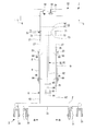
- the side view which looked at the walk assistance device from the left side The figure which shows the attitude
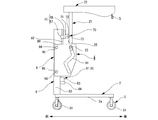
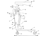
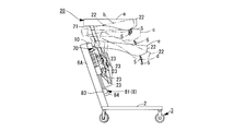
- the walking support device 1 As shown in FIG. 1, the walking support device 1 according to the first embodiment includes a base 2, a moving unit 3 provided on the base 2, a standing seating movement support unit 4 provided on the base 2, and a user A.
- a connecting means 5 for connecting the wearing tool B such as trousers and the upright seating movement support means 4.
- the front side of the user A who uses the walking support device 1, such as a care recipient, a disabled person, and a rehabilitation trainer is “front”, the left side is “left”, the right side is “right”, and the rear side is “ It is defined as “after”.
- the base 2 is configured by a base frame in which, for example, an iron pipe having a circular cross section is formed in a shape such as a concave shape or a U shape.
- a base frame in which, for example, an iron pipe having a circular cross section is formed in a shape such as a concave shape or a U shape.
- the base frame When the base frame is viewed from above, the lower side of the concave shape or U-shape is positioned in front of the walking support device 1, and the left and right upper ends of the concave shape or U-shape are the left and right sides behind the walking support device 1. It is comprised so that it may look like the reverse concave shape and reverse U-shape located in. That is, the base 2 includes a base frame left part 2a that forms the left base, a base frame right part 2b that forms the right base, and a base frame front part 2c that forms the front base.
- the moving means 3 is composed of, for example, a plurality of turning casters (universal casters) 31, 31.
- the swivel caster 31 is attached to the fork 34 so that the wheel 32 can rotate via a central shaft (shaft) 33 that extends parallel (horizontally) to a road surface R such as a floor surface, and the fork 34 is mounted on the road surface.
- it is attached to the base 2 via a mounting seat 36 so as to be rotatable via a central axis (shaft) 35 extending perpendicularly to R.
- a caster with a drum brake unit is used as the turning caster 31, a caster with a drum brake unit is used.
- one swivel caster 31 is provided on each of the rear end side of the base frame left portion 2a, the rear end side of the base frame right portion 2b, and the left and right sides of the base frame front portion 2c. It has been.
- the standing / sitting movement support means 4 is connected to the connection means 5 via the attachment tool B and the operation when the user A who is connected to the connection means 5 via the attachment tool B is seated and stands up. It is a means to support the operation
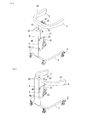
- the standing / sitting motion support means 4 includes a fixed column 6, a lifting member 7, and a lifting member 7 provided along the fixed column 6 so as to rise vertically from the left and right center sides of the base frame front portion 2 c of the base 2. Elevating drive means 8 for elevating and lowering and elevating guide means 9 detachably attached to the fixed column 6.
- the fixed support 6 is formed in, for example, a prismatic shape, and the lower end is fixed to the left and right central sides of the base frame front portion 2c by fixing means such as a mounting bracket, a bolt, and a nut that are not shown.
- the elevating member 7 includes an elevating body 10 that is connected to the elevating driving means 8 and performs an elevating operation, and a support member 20 that is rotatably attached to the elevating body 10 via a hinge 70. .
- the elevating drive means 8 is configured by, for example, a ball screw mechanism 81 provided on the rear surface 61 of the fixed support 6.
- the ball screw mechanism 81 includes a screw shaft 82 provided in parallel with the rear surface 61 of the fixed support 6 and extending in the vertical direction, and a motor 83 that rotates the screw shaft 82.
- the elevating body 10 includes a nut 87 that is attached to the screw shaft 82 and moves up and down as the screw shaft 82 rotates, and a rotation support plate 88 that is attached to the rear surface of the nut 87 and extends in the left-right direction.
- the Accordingly, the rotation of the motor 83 of the ball screw mechanism 81 is transmitted to the screw shaft 82 via the coupling 86 and the screw shaft 82 rotates, so that the elevating body 10 composed of the nut 87 and the rotation support plate 88 is formed. Go up and down.
- the ball screw mechanism 81 has a configuration in which a large number of unillustrated balls are interposed between the screw shaft 82 and the nut 87 to reduce friction between the screw shaft 82 and the nut 87. Therefore, the elevating body 10 moves up and down smoothly.
- the support member 20 includes a movable column 21 that extends in a direction along the fixed column 6 and a support base 22 that is provided so as to extend rearward from the upper end side of the movable column 21 and supports the user A.
- the movable column 21 is formed of, for example, a plate material that extends in the vertical direction.
- the horizontal width dimension of the plate material forming the movable column 21 is shorter than the horizontal width dimension of the fixed column 6 in the horizontal direction.
- the movable column 21 includes, for example, sliders 23 and 23 provided so as to protrude from the left and right side surfaces 27 and 27 on the lower end side, and the left and right front surfaces at the center side in the vertical direction are raised and lowered via a hinge 70. Connected to the body 10.
- a changeover switch 42 is provided for switching whether to perform the operation.
- pillar 21 is formed in the inclined surface extended below, for example toward the back from the front.
- the support base 22 is configured such that the left and right sides extend rearward after extending in the left-right direction from the upper end side of the movable column 21. That is, the support base 22 is a part for the user A to place the left and right forearms or for the user A to hold with the left and right hands, and to support the user A from below.
- the support base 22 is viewed from the upper side, like the base 2, the lower side of the concave shape or U-shape is positioned in front of the walking support device 1 and connected to the upper end side of the movable support column 21.
- the upper left and right ends of the character are configured to look like an inverted concave shape or an inverted U shape located behind the walking support device 1.
- the upper surface 22t of the support base 22 is formed, for example, in a flat surface, and the upper surface 22t forms, for example, a horizontal surface when reaching the uppermost position (see FIG. 4A, FIG. 5C, etc.) during elevation. Further, it is connected to the upper end side of the movable column 21. That is, the support table 22 is connected to the upper end side of the movable column 21 so that the angle formed by the upper surface 22t of the support column 22 and the central axis of the movable column 21 is a right angle.
- the hinge 70 is provided on each of the left and right rear surfaces 89 of the rotation support plate 88 and faces a pair of bearing brackets 71 and 71 and the movable column 21 in the vertical direction.
- the other pair of bearing brackets 72, 72 that are respectively provided on the front side 25 on the left and right sides at the center side of the center and face each other, and are provided so as to pass through the bearing holes of these four bearing brackets 71, 71, 72, 72.
- the rotation center shaft 73 is fixed to one pair of bearing brackets 71, 71 or fixed to the other pair of bearing brackets 72, 72.
- the bearing brackets 72 and 72 of the movable column 21 rotate around the rotation center shaft 73, so that the movable column 21 follows the vertical plane with the rotation center shaft 73 as the rotation center.
- the upper and lower sides of the movable column 21 move in the front-rear direction. That is, the movable support column 21 is configured such that the center side in the vertical direction is connected to the lifting body 10 via the hinge 70, and the vertical side can swing in the front-rear direction around the hinge 70.
- the raising / lowering guide means 9 includes a plate portion 90 and a guide groove 91 formed in the plate portion 90. That is, the plate surface is formed of a plate material extending in the front-rear direction and the vertical direction, and is attached to the side surface 62 of the fixed column 6 with a bolt 96 or the like in a state where the front plate surface and the side surface 62 of the fixed column 6 are in contact.
- the plate portion 90 includes a guide groove 91 that guides the slider 23 provided on the lower end side of the movable support column 21 when the support member 20 is raised and lowered. That is, the lift guide means 9 is formed with a guide groove 91 that guides the vertical movement of the slide 23 when the support member 20 moves up and down when the slider 23 provided on the lower end side of the movable column 21 enters. Consists of plate material.
- the lifting guide means 9 is attached to the side 62 of the fixed column 6 so that the screw 96 is formed on the side 62 of the fixed column 6 and the bolt 96 is passed therethrough.
- a screw shaft (not shown) provided so as to protrude from the side surface 62 of the fixed column 6, a through hole (not shown) formed in the lifting guide means 9 for passing the screw shaft, and the through hole are passed through.
- the guide groove 91 has a configuration in which an upper side guide groove 92, a center side guide groove 93, and a lower side guide groove 94 are continuous.
- the upper side guide groove 92 is formed by a groove extending in the vertical direction at a position away from the fixed column 6, and the lower side guide groove 94.
- the central side guide groove 93 is inclined to connect the lower end of the upper side guide groove 92 and the upper end of the lower side guide groove 94. It is formed by a groove.
- the lifting guide means 9 is attached to the left and right side surfaces 62 and 62 of the fixed column 6, and the slider 23 is respectively connected to the left and right side surfaces 27 and 27 on the lower end side of the movable column 21.
- the left and right sliders 23, 23 are provided so as to protrude, and are configured to move while being guided by the guide grooves 91, 91 of the left / right lifting guide means 9, 9. Accordingly, when the support member 20 is lifted and lowered, the left and right sides of the movable support column 21 are lifted and lowered with the slider 23 and the guide groove 91 being supported by engagement. It is possible to obtain the walking support device 1 in which the support operation is performed stably and reliably.
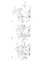
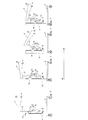
- the walking support device 1 configured as described above, by driving the motor 83, the lifting body 10 is lifted and lowered, and the support member 20 that is rotatably connected to the lifting body 10 via the hinge 70 is lifted and lowered. To do. During this lifting operation, the slider 23 provided on the lower end side of the movable column 21 of the support member 20 moves while being guided by the guide groove 91 of the lifting guide means 9.
- the motor 83 is first driven.
- the support column 22 is inclined downward toward the rear by lowering the movable column 21 to the lowest position.
- the connecting parts C, C, such as retaining rings and the support base 22, which are provided on the left and right sides of the waist of the user A that is provided on the left and right sides of the wearing tool B worn by the user A and seated on the seating part D, After connecting the connecting means 5 and 5 such as hooks provided at the left and right rear ends, the changeover switch 42 is set to the upper side (up).
- the movable column 21 rises while maintaining the vertical state. Therefore, for example, when the support base 22 is attached to the upper end side of the movable support column 21 so that the upper surface 22t of the support table 22 is a surface orthogonal to the extending direction of the movable support column 21,
- the support 22 has an upper surface 22t that gradually approaches horizontal as the upper surface 22t rises from a state inclined from the rear end toward the front upper side, and after the upper surface 22t becomes a horizontal plane, the upper surface 22t is in a horizontal plane state. Continue to rise. That is, the support base 22 is raised while changing its posture as shown by e to a shown in FIGS.
- the changeover switch 42 is used. Set to down (down).
- the motor 83 is driven and the nut 87 connected to the screw shaft 82 is lowered.
- the support member 20 rotatably connected to the nut 87 via the rotation support plate 88 and the hinge 70 is also lowered, so that the user A connected to the support base 22 of the support member 20 also moves downward.
- the support member 20 operates in the reverse direction to the support for the standing motion. That is, the support base 22 is lowered while changing its posture as shown by a to e shown in FIGS.
- connection is connected to the connection portions C, C provided on the wearing tool B worn by the user A.
- the rear end portion of the support base 22 provided with the means 5 and 5 is configured to be positioned below the front end portion of the support base 22. Therefore, at the time of supporting the standing motion, the connecting means 5 and 5 provided at the rear end portion of the support base 22 can be brought close to the connecting portions C and C of the wearing tool B of the user A seated on the seating portion D. Therefore, the operation of connecting the connecting means 5 and 5 and the connecting portions C and C can be easily performed.
- the connecting means 5 and 5 provided at the rear end portion of the support base 22 can be brought close to the position close to the seating portion D, and until the user A is seated on the seating portion D, Since the user A is connected to the support base 22, the user A can perform the sitting operation with peace of mind.
- the operation of releasing the connection between the connecting means 5 and 5 and the connecting portions C and C can be easily performed.
- the support base 22 of the supporting member 20 is lifted while changing its posture so as to gradually rise according to the standing motion of the user A from the state where the rear end portion is lowered.
- the person A can perform a natural standing motion.
- the support member 20 gradually moves from the state in which the upper surface 22t of the support base 22 is horizontal or nearly horizontal to the rear end of the support base 22 in accordance with the seating operation of the user A. Since it descends while changing its posture so that it falls, the user A can perform a natural seating motion.
- the support member 20 includes a structure that is connected via a hinge 70 to a nut 87 that moves up and down by a ball screw mechanism 81 that is an elevating mechanism as an elevating drive unit, and includes a screw shaft 82 and a nut 87.
- the lifting and lowering operation of the support member 20 based on the screwing and the rotation operation of the support member 20 via the hinge 70 are performed separately. Therefore, unlike Patent Document 1, a hinge as a rotation mechanism for rotating the support member is not provided, and the walking support device configured to perform the lifting operation of the support member and the rotation operation of the support member at the same time is compared. According to the first embodiment, it is possible to obtain the walking support device 1 in which the durability of the lifting mechanism, the lifting operation performance of the support member 20, and the rotation operation performance of the support member 20 are improved.
- Embodiment 2 The distance between the rotation center axis of the hinge 70 and the slider 23 can be changed.
- the mounting position of the bearing bracket 72 provided on the movable column 21 and connected to the rotation center shaft 73 of the hinge 70 or the mounting position of the slider 23 provided on the lower end side of the movable column 21 is set to the movable column 21.
- the distance between the rotation center shaft 73 of the hinge 70 and the slider 23 can be changed by configuring the mounting position of the lifting guide means 9 to the fixed column 6 so as to be changeable in the vertical direction. Configured.
- the mounting position of the bearing bracket 72, the mounting position of the slider 23, and the mounting position of the elevating guide means 9 are the same as the mounting target positions of the bearing bracket 72, the slider 23, and the elevating guide means 9.
- a plurality of screw holes for screwing bolts for attaching the guide means 9 may be formed.
- the walking support device according to the first embodiment is configured such that, at the lowest position of the support member 20, the inclination angle of the movable column 21 (the angle formed by the vertical surface (the rear surface 61 of the fixed column) and the extending direction of the movable column 21). It can be larger than 1. That is, the connecting means 5 at the rear end of the support base 22 can be made to reach further downward than the walking support device 1 of the first embodiment, and the walking support device 1 that can cope with the user A having a low seating height. Can provide.
- the distance between the rotation center axis of the hinge 70 and the slider 23 is made longer than that of the walking support device 1 of the first embodiment (see FIG. 2), it can be moved at the lowest position of the support member 20.
- the inclination angle of the column 21 can be made smaller than that of the walking support device 1 of the first embodiment. That is, it is possible to set the position of the connecting means 5 at the rear end portion of the support base 22 at the lowermost position of the support member 20 so as to provide the walking support device 1 that can cope with the user A having a high sitting height. it can. That is, the position of the connecting means 5 at the rear end portion of the support base 22 at the lowest position of the support member 20 can be changed to suit the behavior of the user A and the preference of the user A.
- the movement trajectory of the connecting means 5 accompanying the movement of the support member 20 in the first embodiment when moving up and down does not match the behavior of the user A or does not match the preference of the user A.
- the movement trajectory of the connecting means 5 accompanying the movement of the support member 20 in the first embodiment when moving up and down can be changed. That is, the movement trajectory of the connecting means 5 accompanying the movement of the support member 20 when moving up and down can be changed to one that suits the behavior of the user A and the preference of the user A.
- Embodiment 3 As the lifting guide means 9, a plurality of types of lifting guide means 9 having different forms of the guide grooves 91 are provided, and a plurality of lifting guide means 9 having different forms of the guide grooves 91 can be exchanged for the fixed column 6. It was configured to be attached. As a result, it is possible to provide an upright seating operation according to the preference of the user A.
- the mounting structure for detachably attaching the lifting guide means 9 to the fixed column 6 passes a screw hole 95 formed in the side surface 62 of the fixed column 6 and a bolt 96.
- the structure includes a through-hole or screw hole (not shown) formed in the lifting guide means 9 and a bolt 96 that passes through the through-hole or screw hole and is fastened to the screw hole 95 of the fixing column 8. That's fine.
- the movement trajectory of the connecting means 5 accompanying the movement of the support member 20 in the first and second embodiments when the support member 20 moves up and down is used by replacing the lift guide means 9 with a different shape of the guide groove 91.
- the movement trajectory of the connecting means 5 accompanying the movement of the support member 20 when moving up and down can be selected according to the behavior of the user A and the preference of the user A, the behavior of the user A and the user It is possible to provide the walking support device 1 that can support the standing and sitting motion that suits A's preference.
- Embodiment 4 For example, in FIG. 2, a line connecting the central axis of one bolt 96 and the central axis of the other bolt 96 that fixes the lifting guide means 9 to the fixed column 6 is a radius, and the central axis of one bolt 96 is A plurality of mounting portions (screw holes 95 formed on the side surface 62 of the fixed column 6) of the other bolt 96 are provided on the arc centered on the center, or on the arc centered on the center axis of the other bolt 96 A plurality of mounting portions (screw holes 95 formed in the side surface 62 of the fixed column 6) of the one bolt 96 are provided at one location.
- the mounting portion (mounting position) of the other bolt 96 by changing the mounting portion (mounting position) of the other bolt 96 or by changing the mounting portion (mounting position) of the one bolt 96, the direction of the guide groove 91 of the lifting guide means 9 can be changed. It is possible to change the movement trajectory of the connecting means 5 along with the movement of the support member 20 when the support member 20 moves up and down. Therefore, according to the fourth embodiment, the mounting portion (mounting position) of the other bolt 96 that fixes the lifting guide means 9 to the fixed column 6 is changed, or the mounting portion (mounting position) of one bolt 96 is changed.
- the movement trajectory of the connecting means 5 accompanying the movement of the support member 20 when moving up and down can be changed to one that suits the behavior of the user A and the preference of the user A, the behavior of the user A and the user A It is possible to provide the walking support device 1 that can support the standing-sitting operation that suits the user's preference.
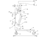
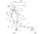
- Embodiment 5 In the first to fourth embodiments, the fixed support 6 provided to stand upright from the left and right center sides of the base frame front portion 2c of the base 2, that is, the fixed support provided to stand up vertically from the front portion of the base 2 is used.
- the walking support device 1 including the support 6 is illustrated, as illustrated in FIGS. 14 to 20, the walking support device 1 including the fixed support 6 ⁇ / b> A provided to rise obliquely forward from the front portion of the base 2.
- FIG. 14 corresponds to FIG. 1
- FIG. 15 corresponds to FIG. 2
- FIG. 16 corresponds to FIG. 6
- FIG. 17 corresponds to FIG. 8
- FIG. 19 and FIG. 19 are diagrams corresponding to FIG. 11
- FIG. 20 is a diagram corresponding to FIG. 12.
- the configuration other than the fixed columns 6 and 6A is the same. These components are denoted by the same reference numerals and description thereof is omitted.
- the walking support device 1 of the fifth embodiment since the fixed support 6A is provided so as to rise obliquely forward from the front portion of the base 2, the left and right rear ends of the support base 22 are supported at the time of supporting the standing motion.
- the connecting means 5 and 5 provided in the section move so as to tilt and rise obliquely forward, so that the user A stands diagonally forward. A more natural standing motion can be performed, and the user A can easily perform the standing motion.
- the moving means 3 may be moving means other than wheels.
- a moving means such as a caster or a caterpillar provided with a ball instead of a wheel may be used, and any moving means configured to be braked may be used.
Landscapes
- Health & Medical Sciences (AREA)
- Epidemiology (AREA)
- Pain & Pain Management (AREA)
- Physical Education & Sports Medicine (AREA)
- Rehabilitation Therapy (AREA)
- Life Sciences & Earth Sciences (AREA)
- Animal Behavior & Ethology (AREA)
- General Health & Medical Sciences (AREA)
- Public Health (AREA)
- Veterinary Medicine (AREA)
- Rehabilitation Tools (AREA)
Abstract
La présente invention vise à fournir une aide à la marche comprenant un mécanisme de levage et d'abaissement ayant une durabilité améliorée et un élément de support ayant une capacité de levage et d'abaissement améliorée et une capacité de rotation améliorée. L'aide à la marche comprend une base 2, un moyen de déplacement 3, un moyen d'aide aux positions debout et assise 4 et un moyen de liaison 5 pour relier un harnais porté par un utilisateur au moyen d'aide aux positions debout et assise 4, le moyen d'aide aux positions debout et assise 4 comprend un support fixe 6 qui est disposé sur la base 2, un élément de levage et d'abaissement 7, un moyen d'entraînement de levage et d'abaissement 8 et un moyen de guidage de levage et d'abaissement 9, l'élément de levage et d'abaissement 7 comprend un corps de levage et d'abaissement 10 qui est relié au moyen d'entraînement de levage et d'abaissement 8 et monte et descend et un élément de support 20 qui est fixé au corps de levage et d'abaissement par l'intermédiaire d'une charnière 70, l'élément de support 20 comprend un support mobile 21 et un appui de support 22, le support mobile 21 a un coulisseau 23 sur une extrémité inférieure et est relié au corps de levage et d'abaissement 10 par l'intermédiaire de la charnière 70, et le moyen de guidage de levage et d'abaissement 9 est fixé au support fixe 6 et a une rainure de guidage 91 qui guide le coulisseau 23 du support mobile 21 lorsque l'élément de support 20 monte et descend.
Priority Applications (1)
| Application Number | Priority Date | Filing Date | Title |
|---|---|---|---|
| CN201880072100.1A CN111328276B (zh) | 2018-03-30 | 2018-12-19 | 行走辅助装置 |
Applications Claiming Priority (4)
| Application Number | Priority Date | Filing Date | Title |
|---|---|---|---|
| JP2018069555A JP7046435B2 (ja) | 2018-03-30 | 2018-03-30 | 歩行支援装置 |
| JP2018-069555 | 2018-03-30 | ||
| JP2018069564A JP7046436B2 (ja) | 2018-03-30 | 2018-03-30 | 歩行支援装置 |
| JP2018-069564 | 2018-03-30 |
Publications (1)
| Publication Number | Publication Date |
|---|---|
| WO2019187406A1 true WO2019187406A1 (fr) | 2019-10-03 |
Family
ID=68058695
Family Applications (1)
| Application Number | Title | Priority Date | Filing Date |
|---|---|---|---|
| PCT/JP2018/046860 Ceased WO2019187406A1 (fr) | 2018-03-30 | 2018-12-19 | Aide à la marche |
Country Status (3)
| Country | Link |
|---|---|
| CN (1) | CN111328276B (fr) |
| TW (1) | TWI714041B (fr) |
| WO (1) | WO2019187406A1 (fr) |
Cited By (1)
| Publication number | Priority date | Publication date | Assignee | Title |
|---|---|---|---|---|
| CN111956460A (zh) * | 2020-09-09 | 2020-11-20 | 郑娟 | 辅助行走器 |
Citations (4)
| Publication number | Priority date | Publication date | Assignee | Title |
|---|---|---|---|---|
| JPH1147206A (ja) * | 1997-08-08 | 1999-02-23 | Sakai Medical Co Ltd | 歩行支援機 |
| JP2007014698A (ja) * | 2005-07-11 | 2007-01-25 | Tokyo Univ Of Science | 歩行補助装置 |
| JP2012030077A (ja) * | 2010-07-30 | 2012-02-16 | Toyota Motor Engineering & Manufacturing North America Inc | 身体補助ロボット装置及びシステム |
| JP2018057631A (ja) * | 2016-10-06 | 2018-04-12 | 株式会社エーアンドエーシステム | 歩行器 |
Family Cites Families (14)
| Publication number | Priority date | Publication date | Assignee | Title |
|---|---|---|---|---|
| JP2001137297A (ja) * | 1999-08-31 | 2001-05-22 | Etou Seisakusho:Kk | 椅子型床走行リフト |
| JP2002224174A (ja) * | 2001-02-02 | 2002-08-13 | Paramount Bed Co Ltd | スタンドアップリフト |
| JP2008036213A (ja) * | 2006-08-08 | 2008-02-21 | Daito Denki Kogyo Kk | 屈伸運動装置 |
| JP3974159B1 (ja) * | 2006-10-26 | 2007-09-12 | 東伸貿易株式会社 | 持ち上げ補助装置 |
| JP5166592B1 (ja) * | 2011-11-30 | 2013-03-21 | 株式会社馬場家具 | 補助機構付き着座具 |
| CN106659621A (zh) * | 2014-09-19 | 2017-05-10 | 松下知识产权经营株式会社 | 就座动作支援系统、就座动作支援系统的控制部的控制方法、就座动作支援系统的控制部用程序、护理带、机器人 |
| JP6542634B2 (ja) * | 2014-12-04 | 2019-07-10 | 株式会社津島鉄工所 | 立ち上がり補助器具および歩行支援装置 |
| JP6462721B2 (ja) * | 2014-12-26 | 2019-01-30 | 株式会社Fuji | 介助ロボット |
| TWM509032U (zh) * | 2015-06-16 | 2015-09-21 | Glorious Union Medtech Corp | 移位復健裝置 |
| JP6616834B2 (ja) * | 2015-07-29 | 2019-12-04 | 株式会社Fuji | 介助ロボット |
| JP2017080247A (ja) * | 2015-10-30 | 2017-05-18 | 株式会社安川電機 | 立ち上がり補助装置、及び立ち上がり補助方法 |
| JP6586472B2 (ja) * | 2016-01-14 | 2019-10-02 | 株式会社Fuji | 介助装置、介助施設、および介助方法 |
| JP6682377B2 (ja) * | 2016-06-20 | 2020-04-15 | 株式会社熊谷組 | 歩行支援装置 |
| JP2017225553A (ja) * | 2016-06-21 | 2017-12-28 | 須恵廣工業株式会社 | 移乗車 |
-
2018
- 2018-12-19 WO PCT/JP2018/046860 patent/WO2019187406A1/fr not_active Ceased
- 2018-12-19 CN CN201880072100.1A patent/CN111328276B/zh active Active
-
2019
- 2019-03-28 TW TW108110913A patent/TWI714041B/zh active
Patent Citations (4)
| Publication number | Priority date | Publication date | Assignee | Title |
|---|---|---|---|---|
| JPH1147206A (ja) * | 1997-08-08 | 1999-02-23 | Sakai Medical Co Ltd | 歩行支援機 |
| JP2007014698A (ja) * | 2005-07-11 | 2007-01-25 | Tokyo Univ Of Science | 歩行補助装置 |
| JP2012030077A (ja) * | 2010-07-30 | 2012-02-16 | Toyota Motor Engineering & Manufacturing North America Inc | 身体補助ロボット装置及びシステム |
| JP2018057631A (ja) * | 2016-10-06 | 2018-04-12 | 株式会社エーアンドエーシステム | 歩行器 |
Cited By (2)
| Publication number | Priority date | Publication date | Assignee | Title |
|---|---|---|---|---|
| CN111956460A (zh) * | 2020-09-09 | 2020-11-20 | 郑娟 | 辅助行走器 |
| CN111956460B (zh) * | 2020-09-09 | 2022-07-08 | 郑娟 | 辅助行走器 |
Also Published As
| Publication number | Publication date |
|---|---|
| TW201941757A (zh) | 2019-11-01 |
| TWI714041B (zh) | 2020-12-21 |
| CN111328276B (zh) | 2022-12-09 |
| CN111328276A (zh) | 2020-06-23 |
Similar Documents
| Publication | Publication Date | Title |
|---|---|---|
| US5730236A (en) | Adjustable powered wheelchair | |
| US5011175A (en) | Wheelchair | |
| JPH05500619A (ja) | 作業ステーシヨンシステム | |
| US6438769B1 (en) | Mobile seat lifting apparatus | |
| KR101409202B1 (ko) | 휠체어 | |
| CN110150892A (zh) | 一种扶手可转动的座椅 | |
| US3848845A (en) | Adjustable seat assembly | |
| JPWO2017134815A1 (ja) | 介助ロボット | |
| JPH10504226A (ja) | 天体観測用仰臥装置 | |
| WO2019187406A1 (fr) | Aide à la marche | |
| JP2011156052A (ja) | 座面傾動椅子 | |
| JP2019177078A (ja) | 歩行支援装置 | |
| JP2019177079A (ja) | 歩行支援装置 | |
| KR101053691B1 (ko) | 전동 스쿠터 | |
| JPH10295749A (ja) | 歩行補助器 | |
| HK40021831B (en) | Walking aid | |
| CN210204068U (zh) | 一种扶手可转动的座椅 | |
| HK40021831A (en) | Walking aid | |
| JP2005040346A (ja) | 高さ可動椅子 | |
| KR101772509B1 (ko) | 방향 전환이 용이하고 중심축이 없는 전동 휠체어 | |
| JP2001057919A (ja) | 昇降椅子 | |
| KR20230102280A (ko) | 체중 지지와 하지 근력 보조가 가능한 보행재활기 | |
| US20250058167A1 (en) | Mobility mechanism for healthy equipment | |
| JP2003325587A (ja) | 車椅子用動力推進装置 | |
| JPS6028250Y2 (ja) | 器機用テ−ブル |
Legal Events
| Date | Code | Title | Description |
|---|---|---|---|
| 121 | Ep: the epo has been informed by wipo that ep was designated in this application |
Ref document number: 18911505 Country of ref document: EP Kind code of ref document: A1 |
|
| 122 | Ep: pct application non-entry in european phase |
Ref document number: 18911505 Country of ref document: EP Kind code of ref document: A1 |