WO2019187539A1 - コネクタ - Google Patents
コネクタ Download PDFInfo
- Publication number
- WO2019187539A1 WO2019187539A1 PCT/JP2019/001817 JP2019001817W WO2019187539A1 WO 2019187539 A1 WO2019187539 A1 WO 2019187539A1 JP 2019001817 W JP2019001817 W JP 2019001817W WO 2019187539 A1 WO2019187539 A1 WO 2019187539A1
- Authority
- WO
- WIPO (PCT)
- Prior art keywords
- holding member
- connector
- screw portion
- rear direction
- male screw
- Prior art date
- Legal status (The legal status is an assumption and is not a legal conclusion. Google has not performed a legal analysis and makes no representation as to the accuracy of the status listed.)
- Ceased
Links
Images










Classifications
-
- G—PHYSICS
- G02—OPTICS
- G02B—OPTICAL ELEMENTS, SYSTEMS OR APPARATUS
- G02B6/00—Light guides; Structural details of arrangements comprising light guides and other optical elements, e.g. couplings
- G02B6/24—Coupling light guides
- G02B6/42—Coupling light guides with opto-electronic elements
- G02B6/4292—Coupling light guides with opto-electronic elements the light guide being disconnectable from the opto-electronic element, e.g. mutually self aligning arrangements
-
- G—PHYSICS
- G02—OPTICS
- G02B—OPTICAL ELEMENTS, SYSTEMS OR APPARATUS
- G02B6/00—Light guides; Structural details of arrangements comprising light guides and other optical elements, e.g. couplings
- G02B6/24—Coupling light guides
- G02B6/36—Mechanical coupling means
-
- G—PHYSICS
- G02—OPTICS
- G02B—OPTICAL ELEMENTS, SYSTEMS OR APPARATUS
- G02B6/00—Light guides; Structural details of arrangements comprising light guides and other optical elements, e.g. couplings
- G02B6/24—Coupling light guides
- G02B6/36—Mechanical coupling means
- G02B6/38—Mechanical coupling means having fibre to fibre mating means
- G02B6/3807—Dismountable connectors, i.e. comprising plugs
- G02B6/389—Dismountable connectors, i.e. comprising plugs characterised by the method of fastening connecting plugs and sockets, e.g. screw- or nut-lock, snap-in, bayonet type
- G02B6/3894—Screw-lock type
-
- G—PHYSICS
- G02—OPTICS
- G02B—OPTICAL ELEMENTS, SYSTEMS OR APPARATUS
- G02B6/00—Light guides; Structural details of arrangements comprising light guides and other optical elements, e.g. couplings
- G02B6/24—Coupling light guides
- G02B6/42—Coupling light guides with opto-electronic elements
-
- G—PHYSICS
- G02—OPTICS
- G02B—OPTICAL ELEMENTS, SYSTEMS OR APPARATUS
- G02B6/00—Light guides; Structural details of arrangements comprising light guides and other optical elements, e.g. couplings
- G02B6/44—Mechanical structures for providing tensile strength and external protection for fibres, e.g. optical transmission cables
- G02B6/4439—Auxiliary devices
- G02B6/444—Systems or boxes with surplus lengths
- G02B6/44528—Patch-cords; Connector arrangements in the system or in the box
-
- G—PHYSICS
- G02—OPTICS
- G02B—OPTICAL ELEMENTS, SYSTEMS OR APPARATUS
- G02B6/00—Light guides; Structural details of arrangements comprising light guides and other optical elements, e.g. couplings
- G02B6/24—Coupling light guides
- G02B6/36—Mechanical coupling means
- G02B6/38—Mechanical coupling means having fibre to fibre mating means
- G02B6/3807—Dismountable connectors, i.e. comprising plugs
- G02B6/381—Dismountable connectors, i.e. comprising plugs of the ferrule type, e.g. fibre ends embedded in ferrules, connecting a pair of fibres
- G02B6/3825—Dismountable connectors, i.e. comprising plugs of the ferrule type, e.g. fibre ends embedded in ferrules, connecting a pair of fibres with an intermediate part, e.g. adapter, receptacle, linking two plugs
Definitions
- the present invention relates to a connector, and more particularly to a connector used for connection between an optical cable and an electronic device.
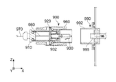
- Patent Document 1 discloses a connector 900 used for connection with an adapter 990.
- the adapter 990 includes a fitting part 992 and an optical module 995.
- a protrusion 993 is provided on the outer peripheral surface of the fitting portion 992.
- the connector 900 includes a cable 970, a coupling body (cable holding unit) 910, a cylinder part 920, an optical connector 930, and an outer cylinder part 960.
- An optical fiber cable 980 that transmits an optical signal is inserted into the cable 970.
- the cable holding unit 910 holds the optical fiber cable 980.
- the cable holding part 910 is attached to the cylinder part 920.
- the tube portion 920 holds the optical connector 930.
- the optical connector 930 is attached to the optical fiber cable 980.
- the optical connector 930 is connected to the optical module 995 when the connector 900 is connected to the adapter 990.
- the outer cylinder part 960 can move within a predetermined range in the front-rear direction (X direction) with respect to the cylinder part 920.
- a groove portion 962 is formed in the outer cylinder portion 960.
- the optical fiber cable between the end 932 of the optical connector 930 and the cable holding unit 910 980 requires a length depending on the size of the connected optical module in the front-rear direction. Accordingly, when the optical fiber cable 980 between the end portion 932 of the optical connector 930 and the cable holding portion 910 is set to have a length determined by the optical module having the smallest size in the front-rear direction, a longer light When the module is replaced, the optical fiber cable 980 between the end portion 932 and the cable holding portion 910 is bent excessively, causing a problem that the optical loss of the optical fiber cable 980 increases.
- an object of the present invention is to provide a connector in which the length of the optical fiber cable does not bend excessively in the connector even when the optical modules having different sizes in the front-rear direction are replaced.
- the cable holding unit holds an optical fiber cable that transmits an optical signal.
- the cable holding part is attached to the first holding member.
- the first holding member holds the optical connector.
- the first holding member has a first male screw portion and a first guide portion.
- the optical connector is attached to the optical fiber cable.
- the optical module is connected to the optical connector.
- the optical module includes a photoelectric conversion unit and an electrical connector.
- the second holding member is located in front of the first holding member in the front-rear direction. The second holding member holds the optical module.
- the second holding member has a second male screw portion and a second guide portion.
- the first guide part and the second guide part cooperate with each other to allow relative movement of the first holding member in the front-rear direction with respect to the second holding member, while in the circumferential direction about an axis parallel to the front-rear direction.
- the relative movement of the first holding member with respect to the second holding member is restricted.
- the coupling nut has a female thread portion. When the female screw portion is engaged with both the first male screw portion and the second male screw portion, the relative positions of the first holding member and the second holding member in the front-rear direction are maintained.
- the connector of the present invention is configured as follows:
- the first holding member that holds the optical connector includes a first male screw portion and a first guide portion; a first holding member that holds the optical module. 2
- the holding member has a second male screw part and a second guide part;
- the coupling nut has a female screw part;
- the first guide part and the second guide part are mutually In cooperation, the relative movement of the first holding member in the front-rear direction with respect to the second holding member is allowed, while the relative movement of the first holding member in the circumferential direction about the axis parallel to the front-rear direction is relative to the second holding member.
- the female screw part meshes with both the first male screw part and the second male screw part, so that the relative position between the first holding member and the second holding member in the front-rear direction is maintained. Accordingly, since the optical fiber cable can have a certain length between the optical connector and the cable holding portion, even if the optical fiber cable is replaced with an optical module having a different size in the front-rear direction, It is avoided that the length is excessively bent.
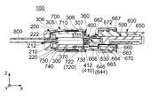
- FIG. 1 It is a perspective view which shows the connector by embodiment of this invention.
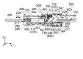
- the female screw portion of the coupling nut is engaged with both the first male screw portion of the first holding member and the second male screw portion of the second holding member.
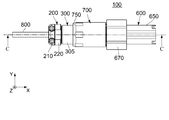
- the female thread portion of the coupling nut is not meshed with either the first male thread portion of the first holding member or the second male thread portion of the second holding member.
- the optical module is hold
- the optical module is connected to an optical connector.
- FIG. 1 shows the optical module contained in the connector of FIG.
- FIG. 4 is a perspective view showing a state where the protruding pieces of the first guide portion of the first holding member are respectively inserted into the grooves of the second guide portion of the second holding member in the connector of FIG. 3.
- the coupling nut is omitted.
- FIG. 4 is another perspective view showing a state where the protruding pieces of the first guide portion of the first holding member are respectively inserted into the grooves of the second guide portion of the second holding member in the connector of FIG. 3.
- the coupling nut is omitted.
- FIG. 4 is the perspective view which expanded a part of connector of FIG.
- FIG. 1 shows the connector of FIG.
- FIG. 1 shows a part of the first male screw part and the second male screw part.
- FIG. 16 is a cross-sectional view showing the connector of FIG. 15 along the line AA.
- the first holding member and a part of the coupling nut are shown in an enlarged manner.
- the projecting pieces of the first guide portion of the first holding member are inserted into the grooves of the second guide portion of the second holding member, respectively, but the female thread portion of the coupling nut is connected to the first holding member.
- FIG. 19 is a cross-sectional view showing the connector of FIG. 18 along the line BB. It is a top view for demonstrating the procedure to replace
- the protruding pieces of the first guide portion of the first holding member are respectively inserted into the grooves of the second guide portion of the second holding member, and the female thread portion of the coupling nut is the second holding member of the second holding member. Although it has meshed with the two male screw portions, it has not meshed with the first male screw portion of the first holding member.
- FIG. 21 is a cross-sectional view showing the connector of FIG.
- FIG. 23 is a cross-sectional view showing the connector of FIG. 22 along the line DD. It is a side view which shows the connector and adapter of patent document 1. FIG. It is sectional drawing which shows the connector and adapter of FIG.
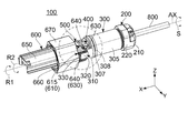
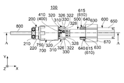
- the connector 100 includes a cable holding unit 200, a first holding member 300, an optical connector 400, an optical module 500, a second holding member 600, and a cup. And a ring nut 700.
- the cable holding unit 200 of the present embodiment is located behind the first holding member 300 in the front-rear direction.
- the rear end of the cable holding unit 200 is the rear end of the connector 100.
- the cable holding unit 200 holds an optical fiber cable 800 that transmits an optical signal.
- the front-rear direction is the X direction.
- the forward direction is the + X direction
- the backward direction is the -X direction.
- the cable holding unit 200 includes a disk part 210 and a cylindrical part 220.
- the disk portion 210 of the present embodiment has a substantially disk shape centered on an axis AX parallel to the front-rear direction.
- the disk part 210 has a hole 212 that penetrates the disk part 210 in the front-rear direction.
- the disk part 210 is located behind the cylinder part 220 in the front-rear direction. More specifically, the front end of the disk part 210 is connected to the rear end of the cylindrical part 220 in the front-rear direction.
- the optical fiber cable 800 is held by the cable holding part 200 so as to penetrate the hole 212 of the disk part 210 of the cable holding part 200.
- the cylindrical portion 220 of the present embodiment has a rotationally symmetric shape with respect to the axis AX. More specifically, the cylindrical portion 220 has a polygonal cylindrical shape extending in the front-rear direction about the axis AX. A female screw 222 is provided on the inner wall of the cylindrical portion 220.
- the first holding member 300 of the present embodiment holds the optical connector 400. More specifically, the first holding member 300 holds the optical connector 400 so as to be movable in the front-rear direction.
- the first holding member 300 of the present embodiment has a first cylindrical portion 305, a first guide portion 310, and a first male screw portion 330.
- the first cylindrical portion 305 of the present embodiment has a substantially cylindrical shape that extends in the front-rear direction about the axis AX.
- the first cylindrical portion 305 includes a front side restriction portion 350, a rear side restriction portion 360, an O-ring 307, a first convex portion 308, and a male screw 306.
- the first holding member 300 has a front side restriction portion 350 and a rear side restriction portion 360.
- each of the front side restricting portions 350 of the present embodiment is located at the front end of the first cylindrical portion 305 in the front-rear direction.
- Each of the front side restricting portions 350 protrudes inward in the radial direction orthogonal to the axis AX. More specifically, each of the front side restriction portions 350 protrudes inward in the lateral direction orthogonal to the front-rear direction.
- the horizontal direction is the Y direction.
- the rear side restricting portion 360 of the present embodiment is located near the front end of the first cylindrical portion 305.
- the rear restricting portion 360 is located behind the front restricting portion 350 in the front-rear direction.
- the rear regulating portion 360 is located in front of the O-ring 307 in the front-rear direction.
- the rear side restricting portion 360 is a plane facing forward in the front-rear direction.
- the O-ring 307 of the present embodiment has an annular shape centering on the axis AX.
- the O ring 307 is disposed on the outer peripheral surface of the first cylindrical portion 305.
- the O ring 307 is arranged near the front end of the first cylindrical portion 305.
- the O ring 307 is located between the rear side restricting portion 360 and the first convex portion 308 in the front-rear direction. That is, the O-ring 307 is located behind the rear side restricting portion 360 and located in front of the first convex portion 308.
- the first convex portion 308 of the present embodiment protrudes radially outward from the outer peripheral surface of the first cylindrical portion 305.
- the first convex portion 308 is located between the O-ring 307 and the male screw 306 in the front-rear direction. That is, the first convex portion 308 is located behind the O-ring 307 and located in front of the male screw 306.
- the male screw 306 of the present embodiment is located at the rear end of the first cylindrical portion 305.
- the male screw 306 is screwed into the female screw 222 of the tube part 220 of the cable holding part 200. That is, the cable holding unit 200 is attached to the first holding member 300.
- the first guide part 310 of the present embodiment extends forward from the front end of the first cylindrical part 305 in the front-rear direction.
- the first guide part 310 includes two projecting pieces 320.
- Each of the projecting pieces 320 extends forward in the front-rear direction.
- the projecting piece 320 has a rectangular shape when viewed from the lateral direction.
- Each of the projecting pieces 320 has an upper surface 322 and a lower surface 324.
- the upper surface 322 is orthogonal to the vertical direction.
- the lower surface 324 is orthogonal to the vertical direction.
- the vertical direction is the Z direction.
- the upper direction is the + Z direction
- the lower direction is the -Z direction.
- Each of the projecting pieces 320 has an outer surface 326 and an inner surface 328.
- the outer surface 326 faces outward in the lateral direction.
- the inner surface 328 faces inward in the lateral direction.
- the inner surface 328 of the projecting piece 320 is positioned outside the front side restricting portion 350 of the first cylindrical portion 305 in the lateral direction.
- the 1st guide part 310 should just be provided with the at least 1 projection piece 320 extended ahead in the front-back direction.
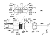
- the first male screw portion 330 of the present embodiment is provided on the protruding piece 320 of the first guide portion 310. More specifically, the first male screw portion 330 is provided on the outer surface 326 of the projecting piece 320, and the screw thread 340 of the first male screw portion 330 protrudes outward in the lateral direction. With reference to FIGS. 8 to 10, the first male screw portion 330 has a screw thread 340. The screw thread 340 of the first male screw portion 330 has an intersecting surface 342. The intersecting surface 342 is located at one end of the screw thread 340 of the first male screw portion 330 in the second rotation direction R2 in the circumferential direction S around the axis AX.
- the intersecting surface 342 intersects the first rotation direction R1.
- the first rotation direction R1 is a direction opposite to the second rotation direction R2. That is, the second rotation direction R2 is the direction opposite to the first rotation direction R1. More specifically, the intersecting surface 342 is inclined so as to extend forward and upward.
- the screw threads 340 of the first male screw portion 330 are arranged at intervals of the pitch P1 in the front-rear direction.
- the first rotation direction R1 is a clockwise direction when the connector 100 is viewed from the front
- the second rotation direction R2 is a counterclockwise direction when the connector 100 is viewed from the front. It is.
- the first holding member 300 further includes a pressing member 370.
- the pressing member 370 is a spring member 370 accommodated in the first holding member 300. More specifically, the spring member 370 is accommodated in the first cylindrical portion 305 of the first holding member 300.
- the spring member 370 of the present embodiment is a coil spring that extends in the front-rear direction.
- an optical connector 400 of the present embodiment connects an optical fiber cable 800 and an optical module 500. That is, the optical connector 400 is attached to the optical fiber cable 800, and the optical connector 400 is configured to be detachable from the optical module 500.
- the optical connector 400 of the present embodiment is held near the front end of the first cylindrical portion 305 of the first holding member 300.
- the front end of the optical connector 400 is located in front of the front end of the first cylindrical portion 305 of the first holding member 300.
- the optical connector 400 is located between the two protrusions 320 of the first holding member 300 in the lateral direction orthogonal to both the front-rear direction and the vertical direction.
- the connection point between the optical connector 400 and the optical module 500 is located in front of the first cylindrical portion 305 of the first holding member 300 in the front-rear direction.
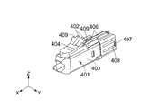
- the optical connector 400 of the present embodiment includes an optical connector main body 401 and an overhanging portion 410.
- the overhanging portion 410 is orthogonal to the front-rear direction.
- the optical connector main body 401 of the present embodiment includes an optical fiber cable housing portion 403, a receiving portion 406, a claw portion 407, a support portion 404, a pressing portion 402, and a locking portion. Part 409.
- the optical fiber cable housing portion 403 of the present embodiment has a substantially rectangular tube shape extending in the front-rear direction.
- each of the receiving portions 406 of the present embodiment is provided on the upper surface of the optical fiber cable housing portion 403 and near the center in the front-rear direction.
- Each of the receiving portions 406 is a rear surface of a protrusion protruding upward in the vertical direction.
- each of the claw portions 407 of the present embodiment is located at the rear end of the optical fiber cable housing portion 403 in the front-rear direction.
- Each of the claw portions 407 has a hook shape protruding outward in the radial direction.
- Each of the claw portions 407 has a front surface 408 facing forward in the front-rear direction.
- Each of the claw portions 407 is movable in the radial direction.
- the support portion 404 of the present embodiment extends rearward and upward from the front end of the upper surface of the optical fiber cable housing portion 403.
- the support portion 404 is supported in a cantilever manner by the optical fiber cable housing portion 403.
- the support portion 404 can be elastically deformed.
- the pressing portion 402 of the present embodiment is located at the upper end and the rear end of the support portion 404.
- each of the locking portions 409 of the present embodiment is a plane that intersects with the front-rear direction.
- Each of the locking portions 409 is located near the rear end of the support portion 404.
- each of the locking portions 409 is movable in the vertical direction. That is, when the pressing portion 402 is pressed from above, the support portion 404 is elastically deformed and the locking portion 409 moves downward. When the pressing to the pressing portion 402 is stopped, the support portion 404 returns to the original shape, and the locking portion 409 moves upward and returns to the original position.
- the overhanging portion 410 of the present embodiment is located near the rear end of the optical connector 400 in the front-rear direction. In the radial direction, the outer periphery of the overhang portion 410 defines the outermost periphery of the optical connector 400.
- the overhanging portion 410 of the present embodiment includes a hole 411, a rear surface 412, an abutting portion 414, a front restricted portion 416, and a rear restricted portion 418. have.
- the rear surface 412 faces rearward in the front-rear direction.
- the abutting portion 414 faces forward in the front-rear direction.
- the hole 411 passes through the overhanging portion 410 in the front-rear direction.
- rear surface 412 is a plane orthogonal to the front-rear direction.
- the abutting portion 414 is a plane orthogonal to the front-rear direction.
- Each of the front side restricted portions 416 is a plane orthogonal to the front-rear direction.
- Each of the front-side restricted portions 416 is located behind the abutting portion 414 in the front-rear direction.
- the rear side restricted portion 418 is a plane orthogonal to the front-rear direction.
- the rear restricted portion 418 is located behind the front restricted portion 416 in the front-rear direction.
- the rear side restricted portion 418 is located outside the rear surface 412 in the radial direction.
- the rear surface 412 and the rear restricted portion 418 are located on the same plane orthogonal to the front-rear direction.
- the overhanging portion 410 of the present embodiment is provided between the front side restriction portion 350 and the rear side restriction portion 360 of the first cylindrical portion 305 of the first holding member 300 in the front-rear direction. positioned. That is, in the front-rear direction, the overhanging portion 410 is located behind the front side restricting portion 350 and is located in front of the rear side restricting portion 360.
- the front regulated portion 416 of the overhanging portion 410 faces the front regulating portion 350 of the first cylindrical portion 305 of the first holding member 300 in the front-rear direction.
- the rear restricted portion 418 of the overhang portion 410 faces the rear restricting portion 360 of the first cylindrical portion 305 of the first holding member 300 in the front-rear direction.
- the overhanging portion 410 is movable by a predetermined distance PD between the front side restriction portion 350 and the rear side restriction portion 360 of the first cylindrical portion 305 of the first holding member 300. That is, the first holding member 300 can move forward by a predetermined distance PD with respect to the optical connector 400.
- the spring member 370 of the first holding member 300 presses the protruding portion 410 forward in the front-rear direction. More specifically, the spring member 370 of the first holding member 300 presses the rear surface 412 of the overhanging portion 410 so that the front restricted portion 416 of the overhanging portion 410 is moved to the front side of the first cylindrical portion 305 of the first holding member 300. Each is pressed against the restriction part 350. That is, the first holding member 300 further includes a pressing member 370 that presses the protruding portion 410 of the optical connector 400 against the front-side regulating portion 350.
- the overhanging portion 410 of this embodiment is held between the receiving portion 406 of the optical connector main body portion 401 and the front surface 408 of the claw portion 407.
- the receiving portion 406 of the optical connector main body 401 faces the abutting portion 414 of the overhanging portion 410 in the front-rear direction.
- the optical module 500 of the present embodiment is an SFP (Small Form-factor Pluggable) module. That is, the optical module 500 transmits an optical signal to the optical connector 400 and receives an optical signal from the optical connector 400.
- SFP Small Form-factor Pluggable
- the optical module 500 of the present embodiment includes an electrical connector 520, a photoelectric conversion unit 510, a locked portion 530, and a locked portion 540.
- the electrical connector 520 inputs and outputs electrical signals to the photoelectric conversion unit 510.
- the photoelectric conversion unit 510 converts between an optical signal and an electronic signal between the optical connector 400 and the electrical connector 520.
- the locked portion 530 protrudes downward in the vertical direction.
- Each of the locked portions 540 is a plane facing forward.
- Each of the locked portions 540 is located near the rear end of the optical module 500.
- the optical module 500 of the present embodiment is connected to the optical connector 400.
- the locked portion 540 (see FIG. 4) of the optical module 500 is positioned behind the locking portion 409 (see FIG. 7) of the optical connector 400 in the front-rear direction. That is, the locked portion 540 of the optical module 500 faces the locking portion 409 of the optical connector 400 in the front-rear direction.
- the optical module 500 is replaceable. A method for replacing the optical module 500 will be described later.
- the second holding member 600 of the present embodiment is located in front of the first holding member 300 in the front-rear direction.
- the front end of the second holding member 600 is the foremost end of the connector 100.
- the second holding member 600 of the present embodiment includes a cover portion 650, a second cylindrical portion 660, a second guide portion 610, a second male screw portion 640, A third male screw portion 644 and an outer cylinder portion 670 are provided.
- the cover portion 650 of the present embodiment has a substantially half-square cylindrical shape.
- the substantially half-square cylindrical shape of the cover portion 650 extends in the front-rear direction and opens downward.
- the cover part 650 is located in front of the second cylindrical part 660 in the front-rear direction. That is, the rear end of the cover portion 650 is connected to the front end of the second cylindrical portion 660 in the front-rear direction.
- the second cylindrical portion 660 of the present embodiment has a rotationally symmetric shape with respect to the axis AX. More specifically, the second cylindrical portion 660 of the present embodiment has a cylindrical shape that extends in the front-rear direction about the axis AX. As shown in FIG. 8, the connection location between the optical connector 400 and the optical module 500 is located behind the second cylindrical portion 660 in the front-rear direction. That is, the connection location between the optical connector 400 and the optical module 500 is located between the first cylindrical portion 305 of the first holding member 300 and the second cylindrical portion 660 of the second holding member 600 in the front-rear direction.
- the second cylindrical portion 660 of the present embodiment has an accommodating portion 662, three O-rings 663, 664, 665, a lock portion 666, and a second convex portion 667. ing.
- the accommodating portion 662 of the present embodiment is a square cylindrical hole that penetrates the second cylindrical portion 660 in the front-rear direction. As shown in FIG. 16, the front end of the accommodating portion 662 is connected to the rear end of the substantially half-angle tube of the cover portion 650. That is, the accommodating portion 662 of the second cylindrical portion 660 and the substantially half-angle tube of the cover portion 650 constitute a space for accommodating the optical module 500.
- each of O-rings 663, 664, and 665 of the present embodiment has an annular shape centering on axis AX.
- Each of the O rings 663, 664, 665 is disposed on the outer peripheral surface of the second cylindrical portion 660.
- the O ring 663 is located at the forefront in the front-rear direction.
- the O ring 665 is located at the rearmost position in the front-rear direction. That is, the O ring 664 is located between the O ring 663 and the O ring 665 in the front-rear direction.
- each of the lock portions 666 of the present embodiment is provided on the lower inner wall of the housing portion 662.
- the lock part 666 fixes the optical module 500 to the second holding member 600 by engaging with the locked part 530 of the optical module 500 when the optical module 500 is inserted into the second holding member 600. Is. That is, in the connector 100 of the present embodiment, the second holding member 600 holds the optical module 500.
- the second convex portion 667 of the present embodiment protrudes outward from the outer peripheral surface of the second cylindrical portion 660 in the radial direction.
- the second convex portion 667 is located between the O-ring 663 and the O-ring 664 in the front-rear direction.
- the second guide portion 610 of the present embodiment extends rearward from the rear end of the second cylindrical portion 660.
- the second guide part 610 includes two grooves 620 and four sandwiching wall parts 630. More specifically, the second guide portion 610 has two sets of guide sets 615 including one groove 620 and two sandwiching wall portions 630.
- the present invention is not limited to this.
- the second guide part 610 only needs to include at least one groove 620 and at least two sandwiching wall parts 630.
- the guide sets 615 of the present embodiment correspond to the protrusions 320 of the first guide part 310 of the first holding member 300, respectively.
- the two sets of guides 615 are positioned at an interval in the lateral direction.
- the sandwiching wall portion 630 sandwiches the groove 620 in the vertical direction perpendicular to the front-rear direction.
- the groove 620 extends in the front-rear direction.
- the groove 620 opens rearward in the front-rear direction.
- the groove 620 is recessed inward in the lateral direction.
- the groove 620 has two wall surfaces 622 and 624 and a side surface 626. Each of the wall surfaces 622 and 624 is orthogonal to the vertical direction.
- the side surface 626 intersects the lateral direction. That is, in the groove 620, the side surface 626 connects the inner ends in the lateral direction of the two wall surfaces 622 and 624 to each other.
- the grooves 620 receive the protruding pieces 320 of the first guide portion 310, respectively.
- the upper wall surface 622 of the groove 620 faces the upper surface 322 of the corresponding protruding piece 320
- the lower wall surface 624 of the groove 620 faces the lower surface 324 of the corresponding protruding piece 320. is doing.
- the side surface 626 of the groove 620 faces the inner surface 328 of the corresponding protruding piece 320.
- the present invention is not limited to this. It is sufficient that at least two sandwiching wall portions 630 sandwich at least one groove 620 in the vertical direction perpendicular to the front-rear direction. Further, at least one groove 620 that extends in the front-rear direction and opens rearward in the front-rear direction only needs to receive at least one protrusion 320 at least partially.
- the protruding piece 320 of the first guide portion 310 of the first holding member 300 is a groove 620 that opens to the rear of the second guide portion 610 of the second holding member 600. Respectively. Accordingly, the relative movement of the first holding member 300 in the front-rear direction with respect to the second holding member 600 is allowed, while the relative movement of the first holding member 300 in the circumferential direction S with respect to the second holding member 600 is restricted. . That is, the first guide part 310 and the second guide part 610 cooperate with each other to allow relative movement in the front-rear direction of the first holding member 300 with respect to the second holding member 600, while being parallel to the front-rear direction. The relative movement of the first holding member 300 with respect to the second holding member 600 in the circumferential direction S around AX is restricted.
- the second male screw portion 640 of the present embodiment is formed on each of the sandwiching wall portions 630.
- a screw thread 642 of the second male screw portion 640 protrudes radially outward.
- the screw threads 642 of the second male screw portion 640 are arranged at intervals of the pitch P2 in the front-rear direction.
- the position of the first male screw part 330 is the same as the position of the second male screw part 640 in the front-rear direction. overlapping.
- the first male screw portion 330 of the projecting piece 320 has the frontmost screw thread 642 and the rearmost screw thread of the second male screw portion 640 of the sandwiching wall portion 630 of the corresponding guide set 615 in the front-rear direction. 642. That is, the size of the first male screw portion 330 is smaller than the size of the second male screw portion 640 in the front-rear direction. Further, the first male screw portion 330 of the projecting piece 320 is positioned between the second male screw portions 640 of the sandwiching wall portion 630 of the corresponding guide set 615 in the vertical direction.
- the third male screw portion 644 of the present embodiment has a substantially semi-cylindrical shape extending in the front-rear direction.
- the third male screw portion 644 extends rearward from the rear end of the second cylindrical portion 660.
- the third male screw portion 644 is positioned between one lower clamping wall portion 630 of the guide set 615 and the remaining lower clamping wall portion 630 of the guide set 615 in the width direction. .
- the third male screw portion 644 connects the lower sandwiching wall portions 630 of the two guide sets 615 to each other in the width direction.
- the screw thread 646 of the third male screw part 644 is connected to the screw thread 642 of the second male screw part 640 in the circumferential direction S.
- the outer cylinder portion 670 of the present embodiment has a shape that is rotationally symmetric with respect to the axis AX. More specifically, the outer cylindrical portion 670 of the present embodiment has a polygonal cylindrical shape that extends in the front-rear direction about the axis AX.
- the outer cylinder part 670 is formed in a larger diameter than the second cylindrical part 660. That is, the outer cylinder part 670 is located outside the second cylindrical part 660 in the radial direction.
- the inner peripheral surface of the outer cylindrical portion 670 and the outer peripheral surface of the second cylindrical portion 660 form a substantially annular space extending in the front-rear direction. As shown in FIG.
- the outer cylindrical portion 670 has a protrusion 672 that protrudes radially inward from the inner peripheral surface.
- the protrusion 672 of the outer cylindrical portion 670 is located behind the second convex portion 667 of the second cylindrical portion 660 in the front-rear direction.
- the coupling nut 700 of the present embodiment has a rotationally symmetric shape with respect to the axis AX. More specifically, the coupling nut 700 of the present embodiment has a substantially cylindrical shape that extends in the front-rear direction about the axis AX. As shown in FIG. 16, the coupling nut 700 is located outside the first holding member 300 in the radial direction.
- the coupling nut 700 of the present embodiment includes a first contact portion 730, a female screw portion 710, a second contact portion 740, and a small diameter portion 750.
- the first contact portion 730 of the present embodiment is a part of the inner peripheral surface of the coupling nut 700.
- the first contact portion 730 is located near the front end of the coupling nut 700.
- the first contact part 730 is The outer cylindrical portion 670 is accommodated in a substantially annular space formed by the inner peripheral surface of the outer cylindrical portion 670 and the outer peripheral surface of the second cylindrical portion 660.
- the first contact portion 730 is in contact with both the O-rings 664 and 665 of the second cylindrical portion 660 of the second holding member 600 in the radial direction.
- the female screw portion 710 of the present embodiment is located behind the first contact portion 730 in the front-rear direction.
- the thread 720 of the female screw portion 710 protrudes inward in the radial direction from the inner peripheral surface of the coupling nut 700.
- the screw threads 720 of the female screw portion 710 are arranged at an interval of a pitch P3 in the front-rear direction.
- the pitch P ⁇ b> 3 of the screw thread 720 of the female screw part 710 is the pitch P ⁇ b> 1 of the screw thread 340 of the first male screw part 330 and the screw thread 642 of the second male screw part 640.
- the pitch P2 is the same.
- the overhanging portion 410 of the optical connector 400 is movable by a predetermined distance PD between the front side restricting portion 350 and the rear side restricting portion 360 of the first holding member 300.
- the predetermined distance PD is larger than the pitch P3 of the female screw portion 710.
- the first male screw portion 330 when the female screw portion 710 is engaged with both the first male screw portion 330 of the first holding member 300 and the second male screw portion 640 of the second holding member 600, the first male screw portion 330 in the front-rear direction.
- the position of is overlapped with the position of the second male screw portion 640.
- the present invention is not limited to this.
- the position of the first male screw part 330 is the same as the position of the second male screw part 640 in the front-rear direction. As long as they overlap.
- the second contact portion 740 is a part of the inner peripheral surface of the coupling nut 700.
- the second contact portion 740 is located behind the female screw portion 710 in the front-rear direction.
- the second contact portion 740 is: In the radial direction, the O-ring 307 of the first cylindrical portion 305 of the first holding member 300 is in contact.
- the coupling is performed.
- the first contact portion 730 and the second contact portion 740 of the nut 700 are connected to the outer peripheral surface of the first cylindrical portion 305 of the first holding member 300 and the second cylinder of the second holding member 600 via the O-rings 307, 664, 665. It is in contact with the outer peripheral surface of the portion 660.
- the connection location between the optical connector 400 and the optical module 500 located between the first cylindrical portion 305 and the second cylindrical portion 660 is blocked from the outside of the connector 100. That is, the connection portion between the optical connector 400 and the optical module 500 is waterproofed from the outside.
- the small-diameter portion 750 of the present embodiment is located at the rear end of the coupling nut 700.
- the small diameter portion 750 projects inward from the inner peripheral surface of the coupling nut 700 in the radial direction.
- the small diameter portion 750 is located behind the second contact portion 740 in the front-rear direction.
- the small diameter part 750 is located behind the first convex part 308 of the first cylindrical part 305 of the first holding member 300 in the front-rear direction.
- the front surface of the small diameter portion 750 is It faces the rear surface of the first convex portion 308 of the first cylindrical portion 305 of the first holding member 300 in the front-rear direction.
- the position of the second holding member 600 when the optical module 500 having a large size in the front-rear direction is mounted is the position of the optical module 500 having a smaller size in the front-rear direction. Compared with the position of the second holding member 600 in the case of mounting, it is further away from the first holding member 300 in the front-rear direction. That is, in the connector 100 of the present embodiment, the difference in the size of the optical module 500 in the front-rear direction is absorbed by the difference in the position in the front-rear direction of the second holding member 600 with respect to the first holding member 300.
- the optical fiber cable 800 can have a certain length between the optical connector 400 and the cable holding unit 200, even if the optical fiber cable 800 is replaced with the optical module 500 having a different size in the front-rear direction, It is avoided that the length of the optical fiber cable 800 is bent excessively.
- the coupling nut 700 is rotated in the second rotation direction R2 in the circumferential direction S with respect to both the first holding member 300 and the second holding member 600.
- the engagement between the female screw portion 710 of the coupling nut 700 and both the first male screw portion 330 of the first holding member 300 and the second male screw portion 640 of the second holding member 600 is released. That is, the coupling nut 700 can be moved behind the first male screw portion 330 of the first holding member 300 and the second male screw portion 640 of the second holding member 600.
- the connector 100 is in the state shown in FIG.
- the second holding member 600 is moved backward with respect to the optical module 500 so that the optical module 500 is inserted from the rear end of the housing portion 662 of the second cylindrical portion 660.
- the holding member 600 is fitted into the first holding member 300.
- the lock part 666 (see FIG. 16) of the second holding member 600 is engaged with the locked part 530 (see FIG. 16) of the optical module 500, and the optical module 500 is fixed to the second holding member 600.
- the connector 100 is in the state shown in FIG.
- the present invention is not limited to this.
- the connector 100 may be in the state shown in FIG. 19 as follows: after the new optical module 500 is fixed to the second holding member 600, the second holding member 600 to which the optical module 500 is fixed is the first.
- the holding member 300 is approached.
- the coupling nut 700 is rotated in the first rotation direction R1 in the circumferential direction S with respect to both the first holding member 300 and the second holding member 600.
- the female screw portion 710 of the coupling nut 700 is engaged with the second male screw portion 640 of the sandwiching wall portion 630 of the second guide portion 610 of the second holding member 600 and the first holding member 300
- the first male threaded portion 330 of the protruding piece 320 of the one guide portion 310 is engaged.
- first male screw portion 330 abuts against the intersecting surface 342 of the thread 340, and a force in the first rotation direction R1 is applied to the intersecting surface 342.
- the first holding member 300 is movable forward by a predetermined distance PD with respect to the optical connector 400. Therefore, referring to FIG. 13, first male screw portion 330 moves forward until female screw portion 710 and first male screw portion 330 are in the same position in the front-rear direction. That is, the shift in the front-rear direction between the female screw portion 710 and the first male screw portion 330 is eliminated.
- the female screw portion 710 is allowed to rotate in the first male member 710 by continuing the rotation of the coupling nut 700 in the first rotational direction R1 with respect to both the first holding member 300 and the second holding member 600.
- the screw portion 330 and the second male screw portion 640 are engaged with each other.
- the difference in the size of the optical module 500 in the front-rear direction is caused by the second holding member 600. It is absorbed by the difference in the position in the front-rear direction with respect to the first holding member 300. Accordingly, the optical fiber cable 800 can have a certain length between the optical connector 400 and the cable holding unit 200. Therefore, even if the optical module 500 is replaced with an optical module 500 having a different size in the front-rear direction, the extra length of the optical fiber cable 800 in the connector 100 can be avoided.
- the first guide part 310 of the present embodiment has two projecting pieces 320
- the second guide part 610 of the present embodiment has two guide sets 615.
- the connector 100 may be configured as follows; the first guide portion 310 has one semi-annular protrusion 320 and the second guide portion 610 has one semi-annular guide. When the semicircular ring of the projecting piece 320 and the semicircular ring of the guide set 615 are combined, one cylinder is formed.
- the first male screw portion 330 of the present embodiment is formed on the first guide portion 310, and the second male screw portion 640 of the present embodiment is formed on the second guide portion 610. It is not limited.
- the first male screw portion 330 may be provided in the first cylindrical portion 305, and the second male screw portion 640 may be provided in the second cylindrical portion 660.
- the female screw portion 710 of the coupling nut 700 is engaged with both the first male screw portion 330 of the first holding member 300 and the second male screw portion 640 of the second holding member 600.
- the position of the first male screw portion 330 overlaps the position of the second male screw portion 640 in the front-rear direction, but the present invention is not limited to this. That is, when the female screw portion 710 of the coupling nut 700 is engaged with both the first male screw portion 330 of the first holding member 300 and the second male screw portion 640 of the second holding member 600, The position of the first male screw portion 330 may not overlap the position of the second male screw portion 640.
- the present invention is based on Japanese Patent Application No. 2018-068775 filed with the Japan Patent Office on March 30, 2018, the contents of which are incorporated herein by reference.
Landscapes
- Physics & Mathematics (AREA)
- General Physics & Mathematics (AREA)
- Optics & Photonics (AREA)
- Mechanical Coupling Of Light Guides (AREA)
- Optical Couplings Of Light Guides (AREA)
Priority Applications (3)
| Application Number | Priority Date | Filing Date | Title |
|---|---|---|---|
| US16/969,595 US11249258B2 (en) | 2018-03-30 | 2019-01-22 | Connector |
| EP19774556.5A EP3739367B1 (de) | 2018-03-30 | 2019-01-22 | Verbinder |
| CN201980014414.0A CN111771148B (zh) | 2018-03-30 | 2019-01-22 | 连接器 |
Applications Claiming Priority (2)
| Application Number | Priority Date | Filing Date | Title |
|---|---|---|---|
| JP2018068775A JP6634464B2 (ja) | 2018-03-30 | 2018-03-30 | コネクタ |
| JP2018-068775 | 2018-03-30 |
Publications (1)
| Publication Number | Publication Date |
|---|---|
| WO2019187539A1 true WO2019187539A1 (ja) | 2019-10-03 |
Family
ID=68059820
Family Applications (1)
| Application Number | Title | Priority Date | Filing Date |
|---|---|---|---|
| PCT/JP2019/001817 Ceased WO2019187539A1 (ja) | 2018-03-30 | 2019-01-22 | コネクタ |
Country Status (5)
| Country | Link |
|---|---|
| US (1) | US11249258B2 (de) |
| EP (1) | EP3739367B1 (de) |
| JP (1) | JP6634464B2 (de) |
| CN (1) | CN111771148B (de) |
| WO (1) | WO2019187539A1 (de) |
Families Citing this family (2)
| Publication number | Priority date | Publication date | Assignee | Title |
|---|---|---|---|---|
| JP6792673B1 (ja) * | 2019-06-25 | 2020-11-25 | 日本航空電子工業株式会社 | プラグコネクタ |
| JP1680801S (de) * | 2020-08-26 | 2021-03-08 |
Citations (9)
| Publication number | Priority date | Publication date | Assignee | Title |
|---|---|---|---|---|
| JPS528835A (en) * | 1975-07-11 | 1977-01-24 | Fujitsu Ltd | Connector for fiber optics |
| JPH02100211U (de) * | 1989-01-30 | 1990-08-09 | ||
| US20050041928A1 (en) * | 2003-09-08 | 2005-02-24 | Zimmel Steven C. | Ruggedized fiber optic connection |
| JP2011107513A (ja) * | 2009-11-19 | 2011-06-02 | Hirose Electric Co Ltd | 防水コネクタ、及び、この防水コネクタを用いた防水装置 |
| JP2012068323A (ja) * | 2010-09-21 | 2012-04-05 | Fujitsu Ltd | 結合デバイス |
| US20120155807A1 (en) * | 2010-12-15 | 2012-06-21 | Innovative Intellectual Properties Llc | Expanded Beam Optical Connector |
| JP2016009011A (ja) * | 2014-06-23 | 2016-01-18 | 第一電子工業株式会社 | 光コネクタ及び該光コネクタを用いたコネクタ装置 |
| WO2016056271A1 (ja) * | 2014-10-10 | 2016-04-14 | 日本航空電子工業株式会社 | コネクタ内蔵プラグ |
| JP2018068775A (ja) | 2016-10-31 | 2018-05-10 | キヤノンメディカルシステムズ株式会社 | 磁気共鳴イメージング装置 |
Family Cites Families (7)
| Publication number | Priority date | Publication date | Assignee | Title |
|---|---|---|---|---|
| JPH1167358A (ja) * | 1997-08-14 | 1999-03-09 | Japan Aviation Electron Ind Ltd | スライドロック式コネクタ |
| US7758389B2 (en) * | 2008-01-25 | 2010-07-20 | Tyco Electronics Corporation | Connector assembly having a movable plug |
| US8272790B2 (en) * | 2009-11-24 | 2012-09-25 | Amphenol Fiber Optics | Outdoor transceiver connector |
| JP5080600B2 (ja) | 2010-02-26 | 2012-11-21 | 日本航空電子工業株式会社 | 光コネクタ内蔵プラグ |
| JP5890273B2 (ja) | 2012-07-27 | 2016-03-22 | 日本航空電子工業株式会社 | プラグ及び光コネクタ接続体 |
| EP3644105B1 (de) * | 2014-06-23 | 2026-02-11 | CommScope Connectivity Belgium BVBA | Glasfaserverbindungssystem mit schnellkupplungsmechanismus |
| JP5860948B1 (ja) * | 2014-12-24 | 2016-02-16 | 日本航空電子工業株式会社 | コネクタ内蔵プラグ |
-
2018
- 2018-03-30 JP JP2018068775A patent/JP6634464B2/ja active Active
-
2019
- 2019-01-22 WO PCT/JP2019/001817 patent/WO2019187539A1/ja not_active Ceased
- 2019-01-22 EP EP19774556.5A patent/EP3739367B1/de active Active
- 2019-01-22 US US16/969,595 patent/US11249258B2/en active Active
- 2019-01-22 CN CN201980014414.0A patent/CN111771148B/zh active Active
Patent Citations (9)
| Publication number | Priority date | Publication date | Assignee | Title |
|---|---|---|---|---|
| JPS528835A (en) * | 1975-07-11 | 1977-01-24 | Fujitsu Ltd | Connector for fiber optics |
| JPH02100211U (de) * | 1989-01-30 | 1990-08-09 | ||
| US20050041928A1 (en) * | 2003-09-08 | 2005-02-24 | Zimmel Steven C. | Ruggedized fiber optic connection |
| JP2011107513A (ja) * | 2009-11-19 | 2011-06-02 | Hirose Electric Co Ltd | 防水コネクタ、及び、この防水コネクタを用いた防水装置 |
| JP2012068323A (ja) * | 2010-09-21 | 2012-04-05 | Fujitsu Ltd | 結合デバイス |
| US20120155807A1 (en) * | 2010-12-15 | 2012-06-21 | Innovative Intellectual Properties Llc | Expanded Beam Optical Connector |
| JP2016009011A (ja) * | 2014-06-23 | 2016-01-18 | 第一電子工業株式会社 | 光コネクタ及び該光コネクタを用いたコネクタ装置 |
| WO2016056271A1 (ja) * | 2014-10-10 | 2016-04-14 | 日本航空電子工業株式会社 | コネクタ内蔵プラグ |
| JP2018068775A (ja) | 2016-10-31 | 2018-05-10 | キヤノンメディカルシステムズ株式会社 | 磁気共鳴イメージング装置 |
Non-Patent Citations (1)
| Title |
|---|
| See also references of EP3739367A4 |
Also Published As
| Publication number | Publication date |
|---|---|
| JP2019179160A (ja) | 2019-10-17 |
| CN111771148B (zh) | 2022-03-22 |
| US11249258B2 (en) | 2022-02-15 |
| EP3739367A4 (de) | 2021-04-21 |
| EP3739367B1 (de) | 2023-03-15 |
| US20210055486A1 (en) | 2021-02-25 |
| CN111771148A (zh) | 2020-10-13 |
| JP6634464B2 (ja) | 2020-01-22 |
| EP3739367A1 (de) | 2020-11-18 |
Similar Documents
| Publication | Publication Date | Title |
|---|---|---|
| JP6402316B2 (ja) | 光コネクタ | |
| JP6363784B1 (ja) | 光コネクタプラグおよび二連式の光コネクタプラグ | |
| US8690454B2 (en) | Optical connector | |
| US20180120517A1 (en) | Floating adjustable sealing mechanism and connector using same | |
| EP2428829B1 (de) | Austauschbarer Linsenvorrichtung | |
| JP2019032432A (ja) | コネクタ装置及びプラグコネクタ | |
| US10432833B2 (en) | Interchangeable lens camera | |
| WO2019187539A1 (ja) | コネクタ | |
| CN104459897A (zh) | 光纤传感器用光纤单元 | |
| JP5573164B2 (ja) | 差込フィルタホルダ | |
| US10036862B2 (en) | Connector | |
| JP5461892B2 (ja) | 顕微鏡 | |
| JP2017146344A (ja) | レンズアクセサリ、レンズ装置、および、撮像装置 | |
| WO2019130580A1 (ja) | 光コネクタ及び光コネクタの接続方法 | |
| WO2017155061A1 (ja) | 光コネクタ | |
| JP5567987B2 (ja) | レンズの倒れ調整装置およびレンズ鏡筒 | |
| JP2013037304A (ja) | フレキシブルプリント配線板の保持方法 | |
| JP2011203682A (ja) | 光コネクタ | |
| WO2016039383A1 (ja) | 光コネクタ | |
| JP6684563B2 (ja) | レンズ装置 | |
| JP2013130796A (ja) | 撮像装置 | |
| JP2011039288A (ja) | 光ファイバー用コネクタ | |
| JP2025064375A (ja) | 交換式レンズ鏡筒 | |
| JP2017173744A (ja) | レンズ支持構造 | |
| JP2020027162A (ja) | アクセサリ及びこれを備えた撮像装置 |
Legal Events
| Date | Code | Title | Description |
|---|---|---|---|
| 121 | Ep: the epo has been informed by wipo that ep was designated in this application |
Ref document number: 19774556 Country of ref document: EP Kind code of ref document: A1 |
|
| ENP | Entry into the national phase |
Ref document number: 2019774556 Country of ref document: EP Effective date: 20200812 |