WO2019187780A1 - リレー - Google Patents
リレー Download PDFInfo
- Publication number
- WO2019187780A1 WO2019187780A1 PCT/JP2019/005931 JP2019005931W WO2019187780A1 WO 2019187780 A1 WO2019187780 A1 WO 2019187780A1 JP 2019005931 W JP2019005931 W JP 2019005931W WO 2019187780 A1 WO2019187780 A1 WO 2019187780A1
- Authority
- WO
- WIPO (PCT)
- Prior art keywords
- wall
- armature
- card
- movable contact
- disposed
- Prior art date
- Legal status (The legal status is an assumption and is not a legal conclusion. Google has not performed a legal analysis and makes no representation as to the accuracy of the status listed.)
- Ceased
Links
Images


Classifications
-
- H—ELECTRICITY
- H01—ELECTRIC ELEMENTS
- H01H—ELECTRIC SWITCHES; RELAYS; SELECTORS; EMERGENCY PROTECTIVE DEVICES
- H01H50/00—Details of electromagnetic relays
- H01H50/64—Driving arrangements between movable part of magnetic circuit and contact
- H01H50/641—Driving arrangements between movable part of magnetic circuit and contact intermediate part performing a rectilinear movement
- H01H50/642—Driving arrangements between movable part of magnetic circuit and contact intermediate part performing a rectilinear movement intermediate part being generally a slide plate, e.g. a card
-
- H—ELECTRICITY
- H01—ELECTRIC ELEMENTS
- H01H—ELECTRIC SWITCHES; RELAYS; SELECTORS; EMERGENCY PROTECTIVE DEVICES
- H01H50/00—Details of electromagnetic relays
- H01H50/02—Bases; Casings; Covers
- H01H50/026—Details concerning isolation between driving and switching circuit
-
- H—ELECTRICITY
- H01—ELECTRIC ELEMENTS
- H01H—ELECTRIC SWITCHES; RELAYS; SELECTORS; EMERGENCY PROTECTIVE DEVICES
- H01H50/00—Details of electromagnetic relays
- H01H50/16—Magnetic circuit arrangements
- H01H50/18—Movable parts of magnetic circuits, e.g. armature
- H01H50/24—Parts rotatable or rockable outside coil
-
- H—ELECTRICITY
- H01—ELECTRIC ELEMENTS
- H01H—ELECTRIC SWITCHES; RELAYS; SELECTORS; EMERGENCY PROTECTIVE DEVICES
- H01H50/00—Details of electromagnetic relays
- H01H50/16—Magnetic circuit arrangements
- H01H50/18—Movable parts of magnetic circuits, e.g. armature
- H01H50/24—Parts rotatable or rockable outside coil
- H01H50/26—Parts movable about a knife edge
-
- H—ELECTRICITY
- H01—ELECTRIC ELEMENTS
- H01H—ELECTRIC SWITCHES; RELAYS; SELECTORS; EMERGENCY PROTECTIVE DEVICES
- H01H50/00—Details of electromagnetic relays
- H01H50/64—Driving arrangements between movable part of magnetic circuit and contact
- H01H50/641—Driving arrangements between movable part of magnetic circuit and contact intermediate part performing a rectilinear movement
-
- H—ELECTRICITY
- H01—ELECTRIC ELEMENTS
- H01H—ELECTRIC SWITCHES; RELAYS; SELECTORS; EMERGENCY PROTECTIVE DEVICES
- H01H50/00—Details of electromagnetic relays
- H01H50/64—Driving arrangements between movable part of magnetic circuit and contact
- H01H50/643—Driving arrangements between movable part of magnetic circuit and contact intermediate part performing a rotating or pivoting movement
- H01H50/644—Driving arrangements between movable part of magnetic circuit and contact intermediate part performing a rotating or pivoting movement having more than one rotating or pivoting part
-
- H—ELECTRICITY
- H01—ELECTRIC ELEMENTS
- H01H—ELECTRIC SWITCHES; RELAYS; SELECTORS; EMERGENCY PROTECTIVE DEVICES
- H01H50/00—Details of electromagnetic relays
- H01H50/02—Bases; Casings; Covers
- H01H2050/028—Means to improve the overall withstanding voltage, e.g. creepage distances
Definitions
- the present invention relates to a relay.
- the armature is operated by electromagnetic force generated from the coil, and the contact is opened and closed by transmitting the armature motion to the movable contact piece.
- a card is disposed between the armature and the movable contact piece.
- the insulation distance between the movable contact piece and the armature is large in order to improve the withstand voltage performance.
- the relay is increased in size.
- An object of the present invention is to extend the insulation distance between the movable contact piece and the armature while suppressing an increase in the size of the relay.
- the relay according to the first aspect includes a fixed terminal, a fixed contact, a movable contact piece, a movable contact, a drive unit, a card, and a wall.
- the fixed contact is connected to the fixed terminal.
- the movable contact piece is disposed to face the fixed terminal.
- the movable contact is connected to the movable contact piece and is disposed to face the fixed contact.
- the drive unit includes a coil and an armature.
- the armature operates by electromagnetic force generated from the coil.
- the card is disposed between the drive unit and the movable contact piece, and transmits the operation of the armature to the movable contact piece.
- the wall portion is disposed between the armature and the card.
- the card includes a card body, a contact portion, and a protrusion.
- the card body is disposed between the wall portion and the movable contact piece.
- the contact portion extends from the card body toward the armature.
- the protrusion protrudes from the card body toward the wall portion and is disposed on the side of the contact portion.
- the wall portion is disposed between the armature and the card.
- the insulation distance between the movable contact piece and the armature can be extended while suppressing an increase in the size of the relay.
- the card is provided with a protrusion that protrudes from the card body toward the wall. Therefore, the insulation distance between the movable contact piece and the armature can be further extended while suppressing the increase in size of the relay.
- the relay may further include a base that supports the fixed terminal, the movable contact piece, and the drive unit.
- the protrusion may extend in the vertical direction.
- the upper direction means the direction in which the movable contact piece extends from the base, and the lower side means the opposite. In this case, the insulation distance between the movable contact piece and the armature can be further expanded because the protrusion has a shape extending in the vertical direction.
- the protrusion may extend from a position above the contact portion to a position below the contact portion.
- the insulation distance between the movable contact piece and the armature can be further expanded by the shape of the protrusions extending greatly in the vertical direction.
- the wall part may include an upper part of the wall located above the contact part.
- the protrusion may extend from a position above the lower end of the upper part of the wall to a position below the lower end of the upper part of the wall.
- the insulation distance between the movable contact piece and the armature can be further expanded by the shape of the protrusions extending greatly in the vertical direction.
- the wall portion may further include a wall side portion.
- the wall side portion may extend from the upper portion of the wall through the side of the contact portion to a position below the contact portion. At least a part of the protrusion may be arranged to face the wall side portion.
- the insulation distance between the movable contact piece and the armature can be increased.
- the insulation distance between a movable contact piece and an armature can further be expanded because at least one part of protrusion is arrange
- the protrusion When viewed from the direction from the movable contact piece toward the drive unit, at least a part of the protrusion may overlap the wall. In this case, the insulation distance between the movable contact piece and the armature can be further increased.
- the contact portion may include a center contact portion, a first extension portion, and a second extension portion.
- the first extending portion may be disposed on one side of the central contact portion and may extend to the drive unit side relative to the central contact portion.
- the second extending portion may be disposed on the other side of the center contact portion and may extend to the drive portion side from the center contact portion.
- the armature may be provided so as to operate by electromagnetic force and press the center contact portion. In this case, the armature can be held from both sides by the first extending portion and the second extending portion. Therefore, the central contact portion of the card can be stably pressed by the armature.
- the central contact portion may have a shape that is convexly curved toward the armature. In this case, the central contact portion of the card can be more stably pressed by the armature.
- the drive unit may further include an iron core inserted into the coil.
- the armature may include a first portion, a second portion, and a third portion.
- the first portion may be disposed to face the iron core.
- the second portion may be disposed to face the contact portion.
- the third part may be located between the first part and the second part.
- the width of the second part may be smaller than the width of the first part. In this case, the width of the second portion facing the contact portion of the card is smaller than the width of the first portion. Therefore, the insulation distance between the movable contact piece and the armature can be further increased. Moreover, since the width
- the width of the second part may be smaller than the width of the third part. In this case, it is possible to ensure a large width of the second portion connecting the first portion and the third portion. Therefore, a decrease in the strength of the armature can be suppressed.
- the second portion may include a first recess and a second recess.
- a first extending portion may be disposed in the first recess.
- a second extending portion may be disposed in the second recess.
- the first extending portion and the second extending portion can be disposed on both sides of the armature while suppressing an increase in the width of the second portion. As a result, while suppressing the increase in the size of the relay.
- the insulation distance between the movable contact piece and the armature can be increased.
- the relay according to the second aspect includes a fixed terminal, a fixed contact, a movable contact piece, a movable contact, a drive unit, a card, and a wall.
- the fixed contact is connected to the fixed terminal.
- the movable contact piece is disposed to face the fixed terminal.
- the movable contact is connected to the movable contact piece and is disposed to face the fixed contact.
- the drive unit includes a coil and an armature.
- the armature operates by electromagnetic force generated from the coil.
- the card is disposed between the drive unit and the movable contact piece, and transmits the operation of the armature to the movable contact piece.
- the wall portion is disposed between the armature and the card.
- the wall portion includes a wall main body and a protrusion.
- the wall body extends in a direction intersecting with the direction from the card toward the drive unit. The protrusion protrudes from the wall body to the card side.
- the wall portion is disposed between the armature and the card.
- the insulation distance between the movable contact piece and the armature can be extended while suppressing an increase in the size of the relay.
- the wall portion is provided with a protrusion protruding from the wall body toward the card side. Therefore, the insulation distance between the movable contact piece and the armature can be further extended while suppressing the increase in size of the relay.
- the relay may further include a base that supports the fixed terminal, the movable contact piece, and the drive unit.
- the protrusion may extend in the vertical direction.
- the upper direction means the direction in which the movable contact piece extends from the base, and the lower side means the opposite. In this case, the insulation distance between the movable contact piece and the armature can be further expanded because the protrusion has a shape extending in the vertical direction.
- the card may include a card body and a contact part.
- the card body may be disposed between the wall portion and the movable contact piece.
- the contact portion may extend from the card body toward the armature and contact the armature.
- the wall body may include an upper wall portion and a wall side portion.
- the upper wall portion may be located above the contact portion.
- the wall side portion may extend from the upper portion of the wall through the side of the contact portion to a position below the contact portion.
- the protrusion may extend from a position above the lower end of the upper part of the wall to a position below the lower end of the upper part of the wall. In this case, since the wall side portion extends through the side of the contact portion, the insulation distance between the movable contact piece and the armature can be increased. Further, since the protrusions extend greatly in the vertical direction, the insulation distance between the movable contact piece and the armature can be further increased.
- the protrusion may extend from a position above the contact portion to a position below the contact portion. In this case, since the protrusion extends greatly in the vertical direction, the insulation distance between the movable contact piece and the armature can be further increased.
- the insulation distance between the movable contact piece and the armature can be extended while suppressing an increase in the size of the relay.
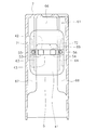
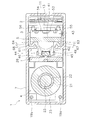
- FIG. 4 is a sectional view taken along line XII-XII in FIG. 3.
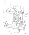
- FIGS. 1 and 2 are perspective views showing a relay 1 according to the embodiment.
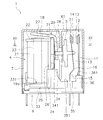
- FIG. 3 is a front view of the relay 1.
- the relay 1 includes a fixed contact portion 2, a movable contact portion 3, a drive portion 4, a card 5, a base 6, and a case 7. 1 and 3, the case 7 is shown in cross section. In FIG. 2, the case 7 is omitted.
- the fixed contact portion 2 includes a fixed terminal 11 and a fixed contact 12.
- the fixed terminal 11 and the fixed contact 12 are made of a conductive material.
- the fixed contact 12 is attached to the fixed terminal 11.
- the fixed terminal 11 is supported by the base 6.
- One end of the fixed terminal 11 protrudes from the base 6 to the outside of the relay 1.
- the other end of the fixed terminal 11 is located in the case 7 and a fixed contact 12 is attached.
- the movable contact portion 3 includes a movable contact piece 13 and a movable contact 14.
- the movable contact piece 13 and the movable contact 14 are made of a conductive material.
- the movable contact piece 13 is supported by the base 6.
- One end of the movable contact piece 13 protrudes from the base 6 to the outside of the relay 1.
- the other end of the movable contact piece 13 is located in the case 7 and a movable contact 14 is attached.
- the movable contact piece 13 is made of an elastic material.
- the movable contact piece 13 is disposed between the fixed terminal 11 and the drive unit 4.
- the movable contact piece 13 is disposed to face the fixed terminal 11.
- the movable contact 14 is disposed to face the fixed contact 12.
- the direction in which the movable contact piece 13 extends from the base 6 in the case 7 is referred to as “upper” and the opposite is referred to as “lower”.
- the definitions of these directions are used for convenience of explanation, and do not limit the arrangement direction of the relay 1 or the like.
- the movable contact piece 13 and the fixed terminal 11 extend upward from the base 6. As shown in FIG. 3, the movable contact piece 13 includes a first bent portion 15 and a second bent portion 16. The second bent portion 16 is located above the first bent portion 15. The movable contact piece 13 is bent toward the fixed terminal 11 at the first bent portion 15. The movable contact piece 13 is bent upward at the second bent portion 16.
- the driving unit 4 generates a driving force for operating the movable contact unit 3.
- the drive unit 4 is supported by the base 6.
- the drive unit 4 includes a coil 21, a bobbin 22, an iron core 23, a yoke 24, and an armature 18.
- the coil 21 is wound around the bobbin 22.
- the axis of the coil 21 extends in the vertical direction.
- the coil 21 is connected to the coil terminals 19a and 19b.
- the coil terminals 19a and 19b are supported by the bobbin 22.
- the iron core 23 is inserted into the bobbin 22.
- the yoke 24 has an L-shaped bent shape.
- the yoke 24 is connected to the iron core 23.
- the yoke 24 has a yoke bottom portion 25 and a yoke side portion 26.
- the yoke bottom portion 25 is disposed below the coil 21.
- the lower end portion of the iron core 23 protrudes downward from the bobbin 22, and the yoke bottom portion 25 is connected to the lower end portion of the iron core 23.
- the yoke side portion 26 is disposed on the side of the coil 21.
- the yoke side portion 26 extends in the vertical direction.
- the armature 18 is rotatably supported at the upper end of the yoke 24.
- the armature 18 operates by electromagnetic force generated from the coil 21.
- the armature 18 is rotatably supported by the upper end portion of the yoke side portion 26.
- the armature 18 has a shape bent in an L shape.
- the armature 18 includes a first portion 27, a second portion 28, and a third portion 29.
- the first portion 27 is disposed above the iron core 23.
- the first portion 27 is disposed to face the iron core 23.
- the second portion 28 is disposed to face the card 5.
- the third portion 29 is located between the first portion 27 and the second portion 28.
- the armature 18 has a bent shape at the third portion 29.
- a hinge spring 31 is attached to the armature 18 and the yoke 24.
- the hinge spring 31 is made of an elastic material. The hinge spring 31 urges the armature 18 in the direction in which the first portion 27 contacts the iron core 23.
- the base 6 is made of an insulating material.
- the base 6 is made of resin. However, the base 6 may be formed of a material other than resin.
- the base 6 supports the fixed contact portion 2, the movable contact portion 3, and the drive portion 4.
- the base 6 includes a coil placement portion 33, a yoke support portion 34, a contact piece support portion 35, and a fixed terminal support portion 36.
- the coil arrangement part 33 is arranged below the coil 21 and the bobbin 22.
- the yoke support portion 34 supports the yoke 24.
- the contact piece support part 35 supports the movable contact piece 13.
- the fixed terminal support part 36 supports the fixed terminal 11.
- the yoke support part 34 covers the lower part of the yoke 24 from the movable contact piece 13 side. As shown in FIG. 3, the upper surface 341 of the yoke support portion 34 is located above the upper surface 331 of the coil placement portion 33. The upper surface 341 of the yoke support portion 34 is located above the upper surface 351 of the contact piece support portion 35. The upper surface 341 of the yoke support portion 34 is located above the upper surface 361 of the fixed terminal support portion 36. The upper surface 341 of the yoke support portion 34 is located above the first bent portion 15 of the movable contact piece 13.
- the card 5 is disposed between the drive unit 4 and the movable contact piece 13.
- the card 5 transmits the operation of the armature 18 to the movable contact piece 13.
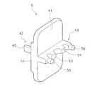
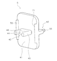
- the card 5 is made of resin. 4 and 5 are perspective views of the card 5.
- FIG. FIG. 6 is a top view of the card 5.
- the card 5 includes a card body 41, a first contact portion 42, and a second contact portion 43.
- the card body 41 has a plate shape extending in the vertical direction.
- FIG. 7 is an enlarged front view of the relay showing the structure around the card.
- the card body 41 is disposed between the movable contact piece 13 and the second portion 28 of the armature 18.
- the first contact portion 42 extends from the card body 41 toward the armature 18.
- the first contact portion 42 is disposed to face the second portion 28 of the armature 18.
- the first contact portion 42 is connected to the second portion 28 of the armature 18.
- the second contact portion 43 is disposed to face the movable contact piece 13.
- the second contact portion 43 is connected to the movable contact piece 13.
- the first contact portion 42 includes a center contact portion 44, a first extension portion 45, and a second extension portion 46.
- the first extending portion 45 is disposed on one side of the central contact portion 44 and extends to the drive portion 4 side from the central contact portion 44.
- the second extending portion 46 is disposed on the other side of the center contact portion 44 and extends to the drive portion 4 side from the center contact portion 44.
- the center contact portion 44 has a shape that is convexly curved toward the armature 18.
- FIG. 8 is a side view of the relay 1.
- FIG. 9 is a perspective view of the armature 18.
- the width W ⁇ b> 2 of the second portion 28 of the armature 18 is smaller than the width W ⁇ b> 1 of the first portion 27.
- the width W2 of the second portion 28 is smaller than the width W3 of the third portion 29.
- the step portions 291 and 292 between the second portion 28 and the third portion 29 are chamfered.
- the corner portions 281 and 282 at the lower end of the second portion 28 are chamfered.
- the chamfering is not limited to a square shape as shown in FIG. 8, but may be a round shape.
- the second portion 28 of the armature 18 includes tapered portions 51 and 52.
- the tapered portion 51 is provided between the third portion 29 and the first recess 47.
- the tapered portion 52 is provided between the third portion 29 and the second recess 48.
- the tapered portions 51 and 52 have a tapered shape toward the lower end of the second portion 28.
- the second portion 28 of the armature 18 includes a first concave portion 47, a second concave portion 48, and a pressing portion 49.
- the pressing portion 49 is disposed between the first recess 47 and the second recess 48. As shown in FIG. 7, the first extending portion 45 of the card 5 is disposed in the first recess 47. Similarly, the second extending portion 46 of the card 5 is disposed in the second recess 48. The pressing portion 49 is disposed between the first extending portion 45 and the second extending portion 46. The pressing portion 49 is disposed to face the central contact portion 44 of the first contact portion 42. When the armature 18 rotates so that the first portion 27 approaches the iron core 23, the pressing portion 49 contacts and presses the central contact portion 44 of the first contact portion 42. Thereby, the operation of the armature 18 is transmitted to the card 5.
- the second contact portion 43 includes a first pressing portion 53, a second pressing portion 54, a first connecting portion 55, and a second connecting portion 56.
- the first pressing portion 53 and the second pressing portion 54 protrude from the tip of the second contact portion 43 toward the movable contact piece 13.
- the first pressing portion 53 and the second pressing portion 54 are disposed to face the movable contact piece 13.
- the first pressing portion 53 and the second pressing portion 54 press the movable contact piece 13 by contacting the movable contact piece 13.
- the first connection portion 55 and the second connection portion 56 protrude from the tip of the second contact portion 43 toward the movable contact piece 13.
- the first connection part 55 and the second connection part 56 are connected to the movable contact piece 13.
- the case 7 is put on the base 6.
- the case 7 is made of an insulating material.
- Case 7 is made of resin.
- the case 7 may be formed of a material other than resin.
- the case 7 has a wall portion 61.
- the wall portion 61 is disposed between the armature 18 and the card 5.
- the wall portion 61 is formed integrally with the case 7.
- the wall 61 may be separate from the case 7.
- FIG. 10 is a perspective view showing a cross section of the case 7.
- the wall portion 61 includes a wall main body 62, a first wall protrusion 63, and a second wall protrusion 64.
- the wall body 62 extends in a direction intersecting with the direction from the card 5 toward the drive unit 4.
- the wall body 62 extends in the vertical direction and is disposed between the armature 18 and the card 5.
- the wall body 62 includes a wall upper portion 66, a first wall side portion 67, and a second wall side portion 68.
- the upper wall portion 66 is located above the first contact portion 42.
- the first wall side portion 67 extends from the wall upper portion 66 through one side of the first connection portion 42 to a position below the first contact portion 42.
- the second wall side portion 68 extends from the wall upper portion 66 through the other side of the first contact portion 42 to a position below the first contact portion 42.
- the wall upper portion 66, the first wall side portion 67, and the second wall side portion 68 form a shape that is recessed upward.
- the first wall protrusion 63 and the second wall protrusion 64 protrude from the wall body 62 to the card 5 side.
- the first wall protrusion 63 and the second wall protrusion 64 extend in the vertical direction.
- a part of the first wall projection 63 is disposed along the first wall side portion 67.
- a part of the second wall projection 64 is disposed along the second wall side portion 68.
- FIG. 11 is a side view showing the wall portion 61 and the card 5.
- the first wall projection 63 and the second wall projection 64 extend from a position above the lower end 69 of the wall upper portion 66 to a position below the lower end 69 of the wall upper portion 66. Yes.
- the first wall protrusion 63 and the second wall protrusion 64 extend from a position above the first contact portion 42 to a position below the first contact portion 42.
- the first wall protrusion 63 and the second wall protrusion 64 extend to a position below the lower end of the armature 18.
- the card body 41 is disposed between the wall portion 61 and the movable contact piece 13.
- the card 5 includes a first card protrusion 71 and a second card protrusion 72.
- the first card protrusion 71 and the second card protrusion 72 protrude from the card body 41 to the wall 61 side.
- the first card protrusion 71 is disposed on one side of the first contact portion 42.
- the second card protrusion 72 is disposed on the other side of the first contact portion 42.
- the first card protrusion 71 and the second card protrusion 72 extend in the vertical direction. As shown in FIG. 11, the first card protrusion 71 and the second card protrusion 72 extend from a position above the first contact portion 42 to a position below the first contact portion 42. The first card protrusion 71 and the second card protrusion 72 extend from a position above the lower end 69 of the wall upper portion 66 to a position below the lower end 69 of the wall upper portion 66. As shown in FIG. 7, the first card protrusion 71 and the second card protrusion 72 extend to a position below the lower end of the armature 18.
- FIG. 12 is a sectional view taken along line XII-XII in FIG.
- first card protrusion 71 is disposed to face the first wall side portion 67.
- second card protrusion 72 is disposed to face the second wall side portion 68.
- the first card protrusion 71 is disposed outside the first wall protrusion 63 in the width direction.
- the second card protrusion 72 is disposed outside the second wall protrusion 64 in the width direction.
- At least a part of the first card protrusion 71 overlaps with the wall portion 61 when viewed from the direction from the movable contact piece 13 toward the drive unit 4.
- at least a part of the second card projection 72 overlaps the wall portion 61.
- at least a part of the first card projection 71 overlaps the first wall side portion 67.
- at least a part of the second card projection 72 overlaps the second wall side portion 68.
- the armature 18 When the coil 21 is energized and the drive unit 4 is in an excited state, the armature 18 is attracted to the iron core 23, thereby resisting the elastic force of the movable contact piece 13 and turning on the center of the upper end of the yoke 24 ( It rotates counterclockwise in FIG.
- the pressing portion 49 of the armature 18 presses the central contact portion 44 of the card 5.
- the card 5 moves in the ON direction (right side in FIG. 7), whereby the first pressing portion 53 and the second pressing portion 54 of the card 5 move in the direction in which the movable contact 14 approaches the fixed contact 12.
- the movable contact piece 13 is pressed. Thereby, the movable contact 14 is pressed against and contacts the fixed contact 12.
- the wall portion 61 is disposed between the armature 18 and the card 5 as shown in FIG. Thereby, the insulation distance between the movable contact piece 13 and the armature 18 can be extended while suppressing the enlargement of the relay 1.
- the card 5 is provided with a first card protrusion 71 and a second card protrusion 72 that protrude from the card body 41 toward the wall 61 side. Therefore, the insulation distance between the movable contact piece 13 and the armature 18 can be further extended while suppressing the increase in size of the relay 1.
- the first card protrusion 71 and the second card protrusion 72 extend in the vertical direction.
- the first card protrusion 71 and the second card protrusion 72 extend from a position above the first contact portion 42 to a position below the first contact portion 42.
- the first card protrusion 71 and the second card protrusion 72 extend from a position above the lower end 69 of the wall upper portion 66 to a position below the lower end 69 of the wall upper portion 66.
- the first card protrusion 71 and the second card protrusion 72 extend greatly in the vertical direction, so that the insulation distance can be further extended.
- the wall portion 61 is provided with a first wall protrusion 63 and a second wall protrusion 64 that protrude from the wall body 62 to the card 5 side. Therefore, the insulation distance between the movable contact piece 13 and the armature 18 can be further extended while suppressing the increase in size of the relay 1.
- the first wall protrusion 63 and the second wall protrusion 64 extend in the vertical direction.
- the first wall projection 63 and the second wall projection 64 extend from a position above the lower end 69 of the wall upper portion 66 to a position below the lower end 69 of the wall upper portion 66.
- the first wall protrusion 63 and the second wall protrusion 64 extend from a position above the first contact portion 42 to a position below the first contact portion 42.
- the first wall protrusion 63 and the second wall protrusion 64 greatly extend in the vertical direction, so that the insulation distance between the movable contact piece 13 and the armature 18 can be further increased. .
- the wall portion 61 includes a first wall side portion 67 and a second wall side portion 68 that extend in the vertical direction. Therefore, the insulation distance between the movable contact piece 13 and the armature 18 can be expanded because the first wall side portion 67 and the second wall side portion 68 extend greatly in the vertical direction.
- the armature 18 is held from both sides by the first extending portion 45 and the second extending portion 46. Therefore, the central contact portion 44 of the card 5 can be stably pressed by the armature 18. Further, the center contact portion 44 has a shape that is convexly curved toward the armature 18. Accordingly, the central contact portion 44 of the card 5 can be more stably pressed by the armature 18.
- the width W 2 of the second portion 28 of the armature 18 is smaller than the width W 1 of the first portion 27. Further, the width W 2 of the second portion 28 is smaller than the width W 3 of the third portion 29. Therefore, the insulation distance between the movable contact piece 13 and the armature 18 can be further increased. Moreover, since the width W1 of the first portion 27 facing the iron core 23 can be maintained large, magnetic loss in the armature 18 can be suppressed. Furthermore, a large width W2 of the second portion 28 connecting the first portion 27 and the third portion 29 can be secured. Therefore, a decrease in strength of the armature 18 can be suppressed.
- the first extension 45 is disposed in the first recess 47 and the second extension 46 is disposed in the second recess 48. Therefore, the first extending portion 45 and the second extending portion 46 can be disposed on both sides of the armature 18 while suppressing an increase in the width W2 of the second portion 28. Thereby, the insulation distance between the movable contact piece 13 and the armature 18 can be increased while suppressing the increase in size of the relay 1.
- the contact configuration of the relay 1 is not limited to the above, and may be changed.
- protrusions are provided on both the card 5 and the wall portion 61.
- only the card 5 of the card 5 and the wall portion 61 may be provided with a protrusion.
- only the wall portion 61 of the card 5 and the wall portion 61 may be provided with a protrusion.
- the configuration of the fixed contact portion 2 may be changed.
- the shape or arrangement of the fixed terminal 11 may be changed.
- the configuration of the movable contact portion 3 may be changed.
- the shape or arrangement of the movable contact piece 13 may be changed.
- the configuration of the drive unit 4 may be changed.
- the shape or arrangement of the coil 21 may be changed.
- the shape or arrangement of the armature 18 or the yoke 24 may be changed.
- the shape or arrangement of the card 5 may be changed.
- the shape or arrangement of the first card protrusion 71 and the second card protrusion 72 may be changed.
- the shape or arrangement of the first contact portion 42 may be changed.
- the shape or arrangement of the second contact portion 43 may be changed.
- the shape or arrangement of the base 6 may be changed.
- the shape or arrangement of the coil placement portion 33, the yoke support portion 34, the contact piece support portion 35, and the fixed terminal support portion 36 may be changed.
- the shape or arrangement of the case 7 may be changed.
- the shape or arrangement of the wall portion 61 may be changed.
- the shape or arrangement of the first wall protrusion 63 and the second wall protrusion 64 may be changed.
- the insulation distance between the movable contact piece and the armature can be extended while suppressing an increase in the size of the relay.
Landscapes
- Physics & Mathematics (AREA)
- Electromagnetism (AREA)
- Electromagnets (AREA)
- Contacts (AREA)
Abstract
壁部は、接極子とカードとの間に配置される。カードは、カード本体と、接触部と、突起とを含む。カード本体は、壁部と可動接触片との間に配置される。接触部は、カード本体から接極子に向かって延びている。突起は、カード本体から壁部側に突出し、接続部の側方に配置される。
Description
本発明は、リレーに関する。
リレーでは、コイルから生じる電磁力によって接極子を動作させ、接極子の動作を可動接触片に伝達することで、接点を開閉する。例えば、特許文献1のリレーでは、接極子と可動接触片との間にカードが配置されている。コイルから生じる電磁力によって接極子が動作すると、接極子の動作がカードを介して可動接触片に伝達される。
上記のようなリレーでは、耐衝撃電圧性能を向上させるために、可動接触片と接極子との間の絶縁距離が大きいことが好ましい。しかし、可動接触片と接極子との間の距離を大きくすると、リレーが大型化してしまう。
本発明の目的は、リレーの大型化を抑えながら、可動接触片と接極子との間の絶縁距離を拡張することにある。
第1の態様に係るリレーは、固定端子と、固定接点と、可動接触片と、可動接点と、駆動部と、カードと、壁部とを備える。固定接点は、固定端子に接続される。可動接触片は、固定端子に対向して配置される。可動接点は、可動接触片に接続され、固定接点に対向して配置される。駆動部は、コイルと接極子とを含む。接極子は、コイルから生じる電磁力により動作する。カードは、駆動部と可動接触片との間に配置され、接極子の動作を可動接触片に伝達する。壁部は、接極子とカードとの間に配置される。
カードは、カード本体と、接触部と、突起とを含む。カード本体は、壁部と可動接触片との間に配置される。接触部は、カード本体から接極子に向かって延びている。突起は、カード本体から壁部側に突出し、接触部の側方に配置される。
本態様に係るリレーでは、接極子とカードとの間に壁部が配置されている。それにより、リレーの大型化を抑えながら、可動接触片と接極子との間の絶縁距離を拡張することができる。また、カードには、カード本体から壁部側に突出する突起が設けられている。そのため、リレーの大型化を抑えながら、可動接触片と接極子との間の絶縁距離をさらに拡張することができる。
リレーは、固定端子と可動接触片と駆動部とを支持するベースをさらに備えてもよい。突起は、上下方向に延びていてもよい。なお、上方は、ベースから可動接触片が延びる方向を意味し、下方は、その反対を意味するものとする。この場合、突起が上下方向に延びた形状であることで、可動接触片と接極子との間の絶縁距離をさらに拡張することができる。
突起は、接触部よりも上方の位置から接触部よりも下方の位置まで延びていてもよい。この場合、突起が上下方向に大きく延びた形状であることで、可動接触片と接極子との間の絶縁距離をさらに拡張することができる。
壁部は、接触部の上方に位置する壁上部を含んでもよい。突起は、壁上部の下端よりも上方の位置から壁上部の下端よりも下方の位置まで延びていてもよい。この場合、突起が上下方向に大きく延びた形状であることで、可動接触片と接極子との間の絶縁距離をさらに拡張することができる。
壁部は、壁側部をさらに含んでもよい。壁側部は、壁上部から接触部の側方を通って接触部よりも下方の位置まで延びていてもよい。突起の少なくとも一部は、壁側部に対向して配置されてもよい。この場合、壁側部が接触部の側方を通って延びていることで、可動接触片と接極子との間の絶縁距離を拡大することができる。また、突起の少なくとも一部が壁側部に対向して配置されることで、可動接触片と接極子との間の絶縁距離をさらに拡大することができる。
可動接触片から駆動部に向かう方向から見て、突起の少なくとも一部は、壁部と重なってもよい。この場合、可動接触片と接極子との間の絶縁距離をさらに拡大することができる。
接触部は、中央接触部と、第1延在部と、第2延在部とを含んでもよい。第1延在部は、中央接触部の一方の側方に配置され、中央接触部よりも駆動部側に延びていてもよい。第2延在部は、中央接触部の他方の側方に配置され、中央接触部よりも駆動部側に延びていてもよい。接極子は、電磁力により動作して中央接触部を押圧するように設けられてもよい。この場合、第1延在部と第2延在部とによって接極子を両側方から保持することができる。そのため、接極子によってカードの中央接触部を安定的に押圧することができる。
中央接触部は、接極子に向かって凸に湾曲した形状を有していてもよい。この場合、接極子によってカードの中央接触部をさらに安定的に押圧することができる。
駆動部は、コイルに挿入される鉄心をさらに含んでもよい。接極子は、第1部分と、第2部分と、第3部分とを含んでもよい。第1部分は、鉄心に対向して配置されてもよい。第2部分は、接触部に対向して配置されてもよい。第3部分は、第1部分と第2部分との間に位置してもよい。第2部分の幅は、第1部分の幅よりも小さくてもよい。この場合、カードの接触部に対向する第2部分の幅が第1部分の幅よりも小さい。そのため、可動接触片と接極子との間の絶縁距離をさらに拡大することができる。また、鉄心に対向する第1部分の幅を大きく維持できるので、接極子における磁気損失を抑えることができる。
第2部分の幅は、第3部分の幅よりも小さくてもよい。この場合、第1部分と第3部分とを接続する第2部分の幅を大きく確保できる。そのため、接極子の強度の低下を抑えることができる。
第2部分は、第1凹部と第2凹部とを含んでもよい。第1凹部には、第1延在部が配置されてもよい。第2凹部には、第2延在部が配置されてもよい。この場合、第2部分の幅が大きくなることを抑えながら、第1延在部と第2延在部とを接極子の両側方に配置することができる。それにより、リレーの大型化を抑えながら。可動接触片と接極子との間の絶縁距離を拡大することができる。
第2の態様に係るリレーは、固定端子と、固定接点と、可動接触片と、可動接点と、駆動部と、カードと、壁部とを備える。固定接点は、固定端子に接続される。可動接触片は、固定端子に対向して配置される。可動接点は、可動接触片に接続され、固定接点に対向して配置される。駆動部は、コイルと接極子とを含む。接極子は、コイルから生じる電磁力により動作する。カードは、駆動部と可動接触片との間に配置され、接極子の動作を可動接触片に伝達する。壁部は、接極子とカードとの間に配置される。壁部は、壁本体と突起とを含む。壁本体は、カードから駆動部に向かう方向と交差する方向に延びている。突起は、壁本体からカード側に突出している。
本態様に係るリレーでは、接極子とカードとの間に壁部が配置されている。それにより、リレーの大型化を抑えながら、可動接触片と接極子との間の絶縁距離を拡張することができる。また、壁部には、壁本体からカード側に突出する突起が設けられている。そのため、リレーの大型化を抑えながら、可動接触片と接極子との間の絶縁距離をさらに拡張することができる。
リレーは、固定端子と可動接触片と駆動部とを支持するベースをさらに備えてもよい。
突起は、上下方向に延びていてもよい。なお、上方は、ベースから可動接触片が延びる方向を意味し、下方は、その反対を意味するものとする。この場合、突起が上下方向に延びた形状であることで、可動接触片と接極子との間の絶縁距離をさらに拡張することができる。
突起は、上下方向に延びていてもよい。なお、上方は、ベースから可動接触片が延びる方向を意味し、下方は、その反対を意味するものとする。この場合、突起が上下方向に延びた形状であることで、可動接触片と接極子との間の絶縁距離をさらに拡張することができる。
カードは、カード本体と接触部とを含んでもよい。カード本体は、壁部と可動接触片との間に配置されてもよい。接触部は、カード本体から接極子に向かって延び、接極子と接触してもよい。壁本体は、壁上部と壁側部とを含んでもよい。壁上部は、接触部の上方に位置してもよい。壁側部は、壁上部から接触部の側方を通って接触部よりも下方の位置まで延びていてもよい。突起は、壁上部の下端よりも上方の位置から壁上部の下端よりも下方の位置まで延びていてもよい。この場合、壁側部が接触部の側方を通って延びていることで、可動接触片と接極子との間の絶縁距離を拡大することができる。また、突起が上下方向に大きく延びていることで、可動接触片と接極子との間の絶縁距離をさらに拡大することができる。
突起は、接触部よりも上方の位置から、接触部よりも下方の位置まで延びていてもよい。この場合、突起が上下方向に大きく延びていることで、可動接触片と接極子との間の絶縁距離をさらに拡大することができる。
本発明によれば、リレーの大型化を抑えながら、可動接触片と接極子との間の絶縁距離を拡張することができる。
以下、図面を参照して実施形態に係るリレーの一例について説明する。図1及び図2は、実施形態に係るリレー1を示す斜視図である。図3は、リレー1の正面図である。図1から図3に示すように、リレー1は、固定接点部2と、可動接点部3と、駆動部4と、カード5と、ベース6と、ケース7とを含む。なお、図1及び図3においては、ケース7が断面で示されている。図2においては、ケース7が省略されている。
固定接点部2は、固定端子11と固定接点12とを含む。固定端子11と固定接点12とは、導電性を有する材料で形成されている。固定接点12は、固定端子11に取り付けられている。固定端子11は、ベース6に支持されている。固定端子11の一端は、ベース6からリレー1の外側へ突出している。固定端子11の他端は、ケース7内に位置しており、固定接点12が取り付けられている。
可動接点部3は、可動接触片13と可動接点14とを含む。可動接触片13と可動接点14とは、導電性を有する材料で形成されている。可動接触片13は、ベース6に支持されている。可動接触片13の一端は、ベース6からリレー1の外側へ突出している。可動接触片13の他端は、ケース7内に位置しており、可動接点14が取り付けられている。可動接触片13は、弾性材で形成されている。可動接触片13は、固定端子11と駆動部4との間に配置されている。可動接触片13は、固定端子11に対向して配置されている。可動接点14は、固定接点12に対向して配置されている。
なお、以下の説明では、ケース7内において、ベース6から可動接触片13が延びる方向を「上」、その反対を「下」と呼ぶものとする。ただし、これらの方向の定義は、説明の便宜上用いられるものであって、リレー1の配置方向等を限定するものではない。
可動接触片13と固定端子11とは、ベース6から上方に延びている。図3に示すように、可動接触片13は、第1屈曲部15と第2屈曲部16とを含む。第2屈曲部16は、第1屈曲部15よりも上方に位置する。可動接触片13は、第1屈曲部15において固定端子11に向かって屈曲している。可動接触片13は、第2屈曲部16において上方に向かって屈曲している。
駆動部4は、可動接点部3を動作させるための駆動力を発生させる。駆動部4は、ベース6に支持されている。駆動部4は、コイル21と、ボビン22と、鉄心23と、ヨーク24と、接極子18とを含む。コイル21は、ボビン22に巻回されている。コイル21の軸線は、上下方向に延びている。コイル21はコイル端子19a,19bに接続されている。コイル端子19a,19bは、ボビン22に支持されている。鉄心23は、ボビン22に挿入されている。
図3に示すように、ヨーク24は、L字型に屈曲した形状を有している。ヨーク24は、鉄心23に接続されている。詳細には、ヨーク24は、ヨーク底部25とヨーク側部26とを有する。ヨーク底部25は、コイル21の下方に配置されている。鉄心23の下端部は、ボビン22から下方に突出しており、ヨーク底部25は、鉄心23の下端部に接続されている。ヨーク側部26は、コイル21の側方に配置される。ヨーク側部26は上下方向に延びている。
接極子18は、ヨーク24の上端部に回動可能に支持されている。接極子18は、コイル21から生じる電磁力により動作する。詳細には、接極子18は、ヨーク側部26の上端部に回動可能に支持されている。接極子18はL字型に屈曲した形状を有している。図3に示すように、接極子18は、第1部分27と、第2部分28と、第3部分29とを含む。第1部分27は、鉄心23の上方に配置されている。第1部分27は、鉄心23に対向して配置されている。第2部分28は、カード5に対向して配置されている。第3部分29は、第1部分27と第2部分28との間に位置する。接極子18は、第3部分29において屈曲した形状を有している。
接極子18とヨーク24とには、ヒンジばね31が取り付けられている。ヒンジばね31は、弾性材で形成されている。ヒンジばね31は、第1部分27が鉄心23に接触する方向に、接極子18を付勢している。
ベース6は、絶縁性を有する材料で形成される。ベース6は、樹脂製である。ただし、ベース6は、樹脂以外の材料で形成されてもよい。ベース6は、固定接点部2と、可動接点部3と、駆動部4とを支持している。ベース6は、コイル配置部33と、ヨーク支持部34と、接触片支持部35と、固定端子支持部36とを含む。コイル配置部33は、コイル21及びボビン22の下方に配置されている。ヨーク支持部34は、ヨーク24を支持している。接触片支持部35は、可動接触片13を支持している。固定端子支持部36は、固定端子11を支持している。
ヨーク支持部34は、ヨーク24の下部を可動接触片13側から覆っている。図3に示すように、ヨーク支持部34の上面341は、コイル配置部33の上面331よりも上方に位置する。ヨーク支持部34の上面341は、接触片支持部35の上面351よりも上方に位置する。ヨーク支持部34の上面341は、固定端子支持部36の上面361よりも上方に位置する。ヨーク支持部34の上面341は、可動接触片13の第1屈曲部15よりも上方に位置している。
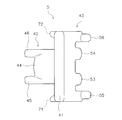
カード5は、駆動部4と可動接触片13との間に配置されている。カード5は、接極子18の動作を可動接触片13に伝達する。カード5は樹脂製である。図4及び図5は、カード5の斜視図である。図6はカード5の上面図である。図4から図6に示すように、カード5は、カード本体41と、第1接触部42と、第2接触部43とを含む。カード本体41は、上下方向に延びる板状の形状を有している。
図7は、カード周囲の構造を示すリレーの拡大正面図である。図7に示すように、カード本体41は、可動接触片13と接極子18の第2部分28との間に配置される。第1接触部42は、カード本体41から接極子18に向かって延びている。第1接触部42は、接極子18の第2部分28に対向して配置されている。第1接触部42は、接極子18の第2部分28に接続されている。第2接触部43は、可動接触片13に対向して配置されている。第2接触部43は、可動接触片13に接続されている。
図6に示すように、第1接触部42は、中央接触部44と、第1延在部45と、第2延在部46とを含む。第1延在部45は、中央接触部44の一方の側方に配置され、中央接触部44よりも駆動部4側に延びている。第2延在部46は、中央接触部44の他方の側方に配置され、中央接触部44よりも駆動部4側に延びている。中央接触部44は、接極子18に向かって凸に湾曲した形状を有している。
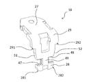
図8は、リレー1の側面図である。図9は、接極子18の斜視図である。なお、図8では、ケース7と、固定接点部2と、可動接点部3と、カード5とが省略されている。図8に示すように、接極子18の第2部分28の幅W2は、第1部分27の幅W1よりも小さい。第2部分28の幅W2は、第3部分29の幅W3よりも小さい。第2部分28と第3部分29との間の段部291,292には、面取りが施されている。第2部分28の下端の角部281,282には、面取りが施されている。なお、面取りは、図8に示すような角型に限らず、丸型であってもよい。
接極子18の第2部分28は、テーパ部51,52を含む。テーパ部51は、第3部分29と第1凹部47との間に設けられている。テーパ部52は、第3部分29と第2凹部48との間に設けられている。テーパ部51,52は、第2部分28の下端に向かって先細りの形状を有している。
接極子18の第2部分28は、第1凹部47と第2凹部48と押圧部49とを含む。押圧部49は、第1凹部47と第2凹部48との間に配置されている。図7に示すように、第1凹部47には、カード5の第1延在部45が配置される。同様に、第2凹部48には、カード5の第2延在部46が配置される。押圧部49は、第1延在部45と第2延在部46との間に配置される。押圧部49は、第1接触部42の中央接触部44と対向して配置されている。第1部分27が鉄心23に近づくように接極子18が回動すると、押圧部49は、第1接触部42の中央接触部44に接触して押圧する。それにより、接極子18の動作がカード5に伝達される。
図4から図6に示すように、第2接触部43は、第1押圧部53と、第2押圧部54と、第1接続部55と、第2接続部56とを含む。第1押圧部53と第2押圧部54とは、第2接触部43の先端から可動接触片13に向かって突出している。第1押圧部53と第2押圧部54とは、可動接触片13に対向して配置される。第1押圧部53と第2押圧部54とは、可動接触片13に接触することで、可動接触片13を押圧する。第1接続部55と第2接続部56とは、第2接触部43の先端から可動接触片13に向かって突出している。第1接続部55と第2接続部56とは、可動接触片13に接続される。
図1に示すように、ケース7は、ベース6に被せられる。ケース7は絶縁性を有する材料で形成される。ケース7は樹脂製である。ただし、ケース7は、樹脂以外の材料で形成されてもよい。図1に示すように、ケース7は、壁部61を有する。壁部61は、接極子18とカード5との間に配置される。壁部61は、ケース7と一体的に形成されている。ただし、壁部61は、ケース7と別体であってもよい。
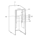
図10は、ケース7の断面を示す斜視図である。図10に示すように、壁部61は、壁本体62と、第1の壁突起63と、第2の壁突起64とを含む。壁本体62は、カード5から駆動部4に向かう方向と交差する方向に延びている。壁本体62は、上下方向に延びており、接極子18とカード5との間に配置される。
壁本体62は、壁上部66と、第1壁側部67と、第2壁側部68とを含む。壁上部66は、第1接触部42の上方に位置する。第1壁側部67は、壁上部66から第1接続部42の一方の側方を通って、第1接触部42よりも下方の位置まで延びている。第2壁側部68は、壁上部66から第1接触部42の他方の側方を通って、第1接触部42よりも下方の位置まで延びている。壁上部66と第1壁側部67と第2壁側部68とによって、上方に向けて凹んだ形状が構成されている。
第1の壁突起63と第2の壁突起64とは、壁本体62からカード5側に突出している。第1の壁突起63と第2の壁突起64とは、上下方向に延びている。第1の壁突起63の一部は、第1壁側部67に沿って配置されている。第2の壁突起64の一部は、第2壁側部68に沿って配置されている。
図11は、壁部61とカード5とを示す側面図である。図11に示すように、第1の壁突起63と第2の壁突起64とは、壁上部66の下端69よりも上方の位置から、壁上部66の下端69よりも下方の位置まで延びている。第1の壁突起63と第2の壁突起64とは、第1接触部42よりも上方の位置から、第1接触部42よりも下方の位置まで延びている。図7に示すように、第1の壁突起63と第2の壁突起64とは、接極子18の下端よりも下方の位置まで延びている。
カード本体41は、壁部61と可動接触片13との間に配置される。図4から図6に示すように、カード5は、第1のカード突起71と第2のカード突起72とを含む。第1のカード突起71と第2のカード突起72とは、カード本体41から壁部61側に突出している。第1のカード突起71は、第1接触部42の一方の側方に配置される。第2のカード突起72は、第1接触部42の他方の側方に配置される。
第1のカード突起71と第2のカード突起72とは、上下方向に延びている。図11に示すように、第1のカード突起71と第2のカード突起72とは、第1接触部42よりも上方の位置から第1接触部42よりも下方の位置まで延びている。第1のカード突起71と第2のカード突起72とは、壁上部66の下端69よりも上方の位置から、壁上部66の下端69よりも下方の位置まで延びている。図7に示すように、第1のカード突起71と第2のカード突起72とは、接極子18の下端よりも下方の位置まで延びている。
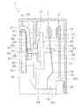
図12は、図3におけるXII-XII断面図である。図12に示すように、第1のカード突起71の少なくとも一部は、第1壁側部67に対向して配置されている。第2のカード突起72の少なくとも一部は、第2壁側部68に対向して配置されている。第1のカード突起71は、幅方向において、第1の壁突起63の外側に配置されている。第2のカード突起72は、幅方向において、第2の壁突起64の外側に配置されている。
図11に示すように、可動接触片13から駆動部4に向かう方向から見て、第1のカード突起71の少なくとも一部は、壁部61と重なる。可動接触片13から駆動部4に向かう方向から見て、第2のカード突起72の少なくとも一部は、壁部61と重なる。可動接触片13から駆動部4に向かう方向から見て、第1のカード突起71の少なくとも一部は、第1壁側部67と重なる。可動接触片13から駆動部4に向かう方向から見て、第2のカード突起72の少なくとも一部は、第2壁側部68と重なる。
次に、リレー1の動作について説明する。コイル21に通電されておらず駆動部4が消磁状態では、接極子18は、鉄心23に吸引されていない。そのため、図7に示すように、可動接点14は、可動接触片13の弾性力によって、固定接点12から離れている。
コイル21に通電され駆動部4が励磁状態となると、接極子18は、鉄心23に吸引されることで、可動接触片13の弾性力に抗して、ヨーク24の上端を中心にオン方向(図7における反時計回り)に回転する。接極子18がオン方向に回転すると、接極子18の押圧部49が、カード5の中央接触部44を押圧する。すると、カード5がオン方向(図7における右方)に移動し、それにより、カード5の第1押圧部53と第2押圧部54とが、可動接点14が固定接点12に近づく方向に、可動接触片13を押圧する。これにより、可動接点14は、固定接点12に押し付けられて接触する。
逆に、コイル21への通電が停止されて駆動部4が消磁状態となると、接極子18の第1部分27は、可動接触片13の弾性力によって、鉄心23から離れるオフ方向(図7における時計回り)に回転する。接極子18がオフ方向に回転すると、接極子18の押圧部49が、カード5の中央接触部44から離れる方向に移動する。すると、カード5が可動接触片13の弾性力によってオフ方向(図7における左方)に移動し、それにより、カード5の第1押圧部53と第2押圧部54とが、可動接点14が固定接点12から離れる方向に、移動する。これにより、可動接点14は、固定接点12から離れる。
以上説明した本実施形態に係るリレー1では、図12に示すように、接極子18とカード5との間に壁部61が配置されている。それにより、リレー1の大型化を抑えながら、可動接触片13と接極子18との間の絶縁距離を拡張することができる。また、カード5には、カード本体41から壁部61側に突出する第1のカード突起71と第2のカード突起72とが設けられている。そのため、リレー1の大型化を抑えながら、可動接触片13と接極子18との間の絶縁距離をさらに拡張することができる。
第1のカード突起71と第2のカード突起72は、上下方向に延びている。第1のカード突起71と第2のカード突起72は、第1接触部42よりも上方の位置から第1接触部42よりも下方の位置まで延びている。第1のカード突起71と第2のカード突起72は、壁上部66の下端69よりも上方の位置から、壁上部66の下端69よりも下方の位置まで延びている。このように、第1のカード突起71と第2のカード突起72とが上下方向に大きく延びていることで、絶縁距離をさらに拡張することができる。
壁部61には、壁本体62からカード5側に突出する第1の壁突起63と第2の壁突起64とが設けられている。そのため、リレー1の大型化を抑えながら、可動接触片13と接極子18との間の絶縁距離をさらに拡張することができる。
第1の壁突起63と第2の壁突起64とは、上下方向に延びている。第1の壁突起63と第2の壁突起64とは、壁上部66の下端69よりも上方の位置から、壁上部66の下端69よりも下方の位置まで延びている。第1の壁突起63と第2の壁突起64とは、第1接触部42よりも上方の位置から、第1接触部42よりも下方の位置まで延びている。このように、第1の壁突起63と第2の壁突起64とが上下方向に大きく延びていることで、可動接触片13と接極子18との間の絶縁距離をさらに拡大することができる。
壁部61は、上下方向に延びる第1壁側部67と第2壁側部68とを含む。従って、第1壁側部67と第2壁側部68とが上下方向に大きく延びていることで、可動接触片13と接極子18との間の絶縁距離を拡大することができる。
可動接触片13から駆動部4に向かう方向から見て、第1のカード突起71の少なくとも一部と第2のカード突起72の少なくとも一部とは、壁部61と重なっている。また、第1のカード突起71の少なくとも一部は、第1壁側部67に対向して配置される。第2のカード突起72の少なくとも一部は、第2壁側部68に対向して配置される。それにより、可動接触片13と接極子18との間の絶縁距離をさらに拡大することができる。
第1延在部45と第2延在部46とによって接極子18が両側方から保持されている。そのため、接極子18によってカード5の中央接触部44を安定的に押圧することができる。また、中央接触部44は、接極子18に向かって凸に湾曲した形状を有している。それにより、接極子18によってカード5の中央接触部44をさらに安定的に押圧することができる。
接極子18の第2部分28の幅W2は、第1部分27の幅W1よりも小さい。また、第2部分28の幅W2は、第3部分29の幅W3よりも小さい。そのため、可動接触片13と接極子18との間の絶縁距離をさらに拡大することができる。また、鉄心23に対向する第1部分27の幅W1を大きく維持できるので、接極子18における磁気損失を抑えることができる。さらに、第1部分27と第3部分29とを接続する第2部分28の幅W2を大きく確保できる。そのため、接極子18の強度の低下を抑えることができる。
接極子18において、第1凹部47に第1延在部45が配置され、第2凹部48に第2延在部46が配置される。そのため、第2部分28の幅W2が大きくなることを抑えながら、第1延在部45と第2延在部46とを接極子18の両側方に配置することができる。それにより、リレー1の大型化を抑えながら、可動接触片13と接極子18との間の絶縁距離を拡大することができる。
以上、本発明の一実施形態について説明したが、本発明は上記実施形態に限定されるものではなく、発明の要旨を逸脱しない範囲で種々の変更が可能である。
リレー1の接点構成は上記のものに限らず、変更されてもよい。上記の実施形態では、カード5と壁部61との両方に突起が設けられている。しかし、カード5と壁部61のうちカード5のみに突起が設けられてもよい。或いは、カード5と壁部61とのうち壁部61のみに突起が設けられてもよい。
固定接点部2の構成は変更されてもよい。例えば、固定端子11の形状、或いは配置が変更されてもよい。可動接点部3の構成が変更されてもよい。例えば、可動接触片13の形状、或いは配置が変更されてもよい。駆動部4の構成は変更されてもよい。例えば、コイル21の形状、或いは配置が変更されてもよい。接極子18、或いはヨーク24の形状、或いは配置が変更されてもよい。
カード5の形状、或いは配置が変更されてもよい。第1のカード突起71と第2のカード突起72との形状、或いは配置が変更されてもよい。第1接触部42の形状、或いは配置が変更されてもよい。第2接触部43の形状、或いは配置が変更されてもよい。
ベース6の形状、或いは配置が変更されてもよい。例えば、コイル配置部33、ヨーク支持部34、接触片支持部35、固定端子支持部36の形状、或いは配置が変更されてもよい。
ケース7の形状、或いは配置が変更されてもよい。例えば、壁部61の形状、或いは配置が変更されてもよい。第1の壁突起63と第2の壁突起64との形状、或いは配置が変更されてもよい。
本発明によれば、リレーの大型化を抑えながら、可動接触片と接極子との間の絶縁距離を拡張することができる。
4・・・駆動部、5・・・カード、6・・・ベース、11・・・固定端子、12・・・固定接点、13・・・可動接触片、14・・・可動接点、18・・・接極子、21・・・コイル、23・・・鉄心、27・・・第1部分、28・・・第2部分、29・・・第3部分、41・・・カード本体、42・・・第1接触部、44・・・中央接触部、45・・・第1延在部、46・・・第2延在部、47・・・第1凹部、48・・・第2凹部、62・・・壁本体、61・・・壁部、63・・・第1の壁突起、66・・・壁上部、67・・・第1壁側部、71・・・第1のカード突起
Claims (15)
- 固定端子と、
前記固定端子に接続された固定接点と、
前記固定端子に対向して配置された可動接触片と、
前記可動接触片に接続され、前記固定接点に対向して配置された可動接点と、
コイルと、前記コイルから生じる電磁力により動作する接極子とを含む駆動部と、
前記駆動部と前記可動接触片との間に配置され、前記接極子の動作を前記可動接触片に伝達するカードと、
前記接極子と前記カードとの間に配置される壁部と、
を備え、
前記カードは、
前記壁部と前記可動接触片との間に配置されるカード本体と、
前記カード本体から前記接極子に向かって延び、前記接極子と接触する接触部と、
前記カード本体から前記壁部側に突出し、前記接触部の側方に配置される突起と、
を含む、
リレー。 - 前記固定端子と前記可動接触片と前記駆動部とを支持するベースをさらに備え、
前記ベースから前記可動接触片が延びる方向を上方、その反対を下方として、
前記突起は、上下方向に延びている、
請求項1に記載のリレー。 - 前記突起は、前記接触部よりも上方の位置から前記接触部よりも下方の位置まで延びている、
請求項2に記載のリレー。 - 前記壁部は、前記接触部の上方に位置する壁上部を含み、
前記突起は、前記壁上部の下端よりも上方の位置から前記壁上部の下端よりも下方の位置まで延びている、
請求項2又は3に記載のリレー。 - 前記壁部は、前記壁上部から前記接触部の側方を通って前記接触部よりも下方の位置まで延びる壁側部をさらに含み、
前記突起の少なくとも一部は、前記壁側部に対向して配置されている、
請求項2から4のいずれかに記載のリレー。 - 前記可動接触片から前記駆動部に向かう方向から見て、前記突起の少なくとも一部は、前記壁部と重なる、
請求項1から5のいずれかに記載のリレー。 - 前記接触部は、
中央接触部と、
前記中央接触部の一方の側方に配置され、前記中央接触部よりも前記駆動部側に延びる第1延在部と、
前記中央接触部の他方の側方に配置され、前記中央接触部よりも前記駆動部側に延びる第2延在部と、
を含み、
前記接極子は、前記電磁力により動作して前記中央接触部を押圧するように設けられる、
請求項1から6のいずれかに記載のリレー。 - 前記中央接触部は、前記接極子に向かって凸に湾曲した形状を有している、
請求項7に記載のリレー。 - 前記駆動部は、前記コイルに挿入される鉄心をさらに含み、
前記接極子は、
前記鉄心に対向して配置される第1部分と、
前記接触部に対向して配置される第2部分と、
前記第1部分と前記第2部分との間に位置する第3部分と、
を含み、
前記第2部分の幅は、前記第1部分の幅よりも小さい、
請求項7又は8に記載のリレー。 - 前記第2部分の幅は、前記第3部分の幅よりも小さい、
請求項9に記載のリレー。 - 前記第2部分は、
前記第1延在部が配置される第1凹部と、
前記第2延在部が配置される第2凹部と、
を含む、
請求項7から10のいずれかに記載のリレー。 - 固定端子と、
前記固定端子に接続された固定接点と、
前記固定端子に対向して配置された可動接触片と、
前記可動接触片に取り付けられ、前記固定接点に対向して配置された可動接点と、
コイルと、前記コイルから生じる電磁力により動作する接極子とを含む駆動部と、
前記駆動部と前記可動接触片との間に配置され、前記接極子の動作を前記可動接触片に伝達するカードと、
前記接極子と前記カードとの間に配置される壁部と、
を備え、
前記壁部は、
前記カードから前記駆動部に向かう方向と交差する方向に延びる壁本体と、
前記壁本体から前記カード側に突出する突起と、
を含む、
リレー。 - 前記固定端子と前記可動接触片と前記駆動部とを支持するベースをさらに備え、
前記ベースから前記可動接触片が延びる方向を上方、その反対を下方として、
前記突起は、上下方向に延びている、
請求項12に記載のリレー。 - 前記カードは、
前記壁部と前記可動接触片との間に配置されるカード本体と、
前記カード本体から前記接極子に向かって延び、前記接極子と接触する接触部と、
を含み、
前記壁本体は、
前記接触部の上方に位置する壁上部と、
前記壁上部から前記接触部の側方を通って前記接触部よりも下方の位置まで延びる壁側部と、
を含み、
前記突起は、前記壁上部の下端よりも上方の位置から前記壁上部の下端よりも下方の位置まで延びている、
請求項13に記載のリレー。 - 前記突起は、前記接触部よりも上方の位置から、前記接触部よりも下方の位置まで延びている、
請求項13又は14に記載のリレー。
Priority Applications (3)
| Application Number | Priority Date | Filing Date | Title |
|---|---|---|---|
| EP19775648.9A EP3770941B1 (en) | 2018-03-27 | 2019-02-18 | Relay |
| US16/979,865 US11322327B2 (en) | 2018-03-27 | 2019-02-18 | Relay |
| CN201980016501.XA CN111801763B (zh) | 2018-03-27 | 2019-02-18 | 继电器 |
Applications Claiming Priority (2)
| Application Number | Priority Date | Filing Date | Title |
|---|---|---|---|
| JP2018060044A JP7003787B2 (ja) | 2018-03-27 | 2018-03-27 | リレー |
| JP2018-060044 | 2018-03-27 |
Publications (1)
| Publication Number | Publication Date |
|---|---|
| WO2019187780A1 true WO2019187780A1 (ja) | 2019-10-03 |
Family
ID=68058290
Family Applications (1)
| Application Number | Title | Priority Date | Filing Date |
|---|---|---|---|
| PCT/JP2019/005931 Ceased WO2019187780A1 (ja) | 2018-03-27 | 2019-02-18 | リレー |
Country Status (5)
| Country | Link |
|---|---|
| US (1) | US11322327B2 (ja) |
| EP (1) | EP3770941B1 (ja) |
| JP (1) | JP7003787B2 (ja) |
| CN (1) | CN111801763B (ja) |
| WO (1) | WO2019187780A1 (ja) |
Families Citing this family (2)
| Publication number | Priority date | Publication date | Assignee | Title |
|---|---|---|---|---|
| JP7003787B2 (ja) * | 2018-03-27 | 2022-01-21 | オムロン株式会社 | リレー |
| JP7700543B2 (ja) * | 2021-07-05 | 2025-07-01 | オムロン株式会社 | 電磁継電器 |
Citations (5)
| Publication number | Priority date | Publication date | Assignee | Title |
|---|---|---|---|---|
| JPH11213839A (ja) * | 1998-01-27 | 1999-08-06 | Matsushita Electric Works Ltd | 電磁継電器 |
| JP2000076977A (ja) * | 1998-08-31 | 2000-03-14 | Matsushita Electric Works Ltd | 電磁リレー |
| JP2004158382A (ja) * | 2002-11-08 | 2004-06-03 | Omron Corp | 電磁継電器 |
| JP2012160325A (ja) | 2011-01-31 | 2012-08-23 | Panasonic Corp | 電磁リレー |
| JP2013218883A (ja) * | 2012-04-09 | 2013-10-24 | Omron Corp | 電磁継電器 |
Family Cites Families (13)
| Publication number | Priority date | Publication date | Assignee | Title |
|---|---|---|---|---|
| DE7309137U (de) * | 1973-03-10 | 1973-07-12 | Bach & Co | Betätigungselement zur Kontaktsatz-Betätigung in einem Relais oder dgl |
| JPH0469836U (ja) * | 1990-10-26 | 1992-06-19 | ||
| JP3552406B2 (ja) * | 1996-05-31 | 2004-08-11 | オムロン株式会社 | 電磁継電器 |
| JP4307182B2 (ja) | 2003-08-22 | 2009-08-05 | 富士通コンポーネント株式会社 | 電磁継電器 |
| JP4677916B2 (ja) * | 2006-02-08 | 2011-04-27 | オムロン株式会社 | 電磁継電器 |
| JP5058643B2 (ja) * | 2007-03-26 | 2012-10-24 | 富士通コンポーネント株式会社 | 電磁継電器 |
| CN201667321U (zh) * | 2010-04-12 | 2010-12-08 | 宁波天波港联电子有限公司 | 继电器 |
| CN203288516U (zh) * | 2013-05-13 | 2013-11-13 | 安徽省明光市爱福电子有限公司 | 一种输入和输出完全隔开的高耐压继电器 |
| CN203367171U (zh) * | 2013-07-02 | 2013-12-25 | 安徽省明光市爱福电子有限公司 | 一种衔铁、推动卡、动簧片连动结构 |
| CN107305825B (zh) * | 2017-07-11 | 2019-09-06 | 厦门宏发电力电器有限公司 | 一种带片型推动卡的电磁继电器 |
| CN207052535U (zh) * | 2017-07-21 | 2018-02-27 | 欣大电气有限公司 | 抗浪涌小型电磁继电器 |
| CN107644788B (zh) * | 2017-10-10 | 2020-07-10 | 三友联众集团股份有限公司 | 一种推片转动式继电器 |
| JP7003787B2 (ja) * | 2018-03-27 | 2022-01-21 | オムロン株式会社 | リレー |
-
2018
- 2018-03-27 JP JP2018060044A patent/JP7003787B2/ja active Active
-
2019
- 2019-02-18 US US16/979,865 patent/US11322327B2/en active Active
- 2019-02-18 EP EP19775648.9A patent/EP3770941B1/en active Active
- 2019-02-18 CN CN201980016501.XA patent/CN111801763B/zh active Active
- 2019-02-18 WO PCT/JP2019/005931 patent/WO2019187780A1/ja not_active Ceased
Patent Citations (5)
| Publication number | Priority date | Publication date | Assignee | Title |
|---|---|---|---|---|
| JPH11213839A (ja) * | 1998-01-27 | 1999-08-06 | Matsushita Electric Works Ltd | 電磁継電器 |
| JP2000076977A (ja) * | 1998-08-31 | 2000-03-14 | Matsushita Electric Works Ltd | 電磁リレー |
| JP2004158382A (ja) * | 2002-11-08 | 2004-06-03 | Omron Corp | 電磁継電器 |
| JP2012160325A (ja) | 2011-01-31 | 2012-08-23 | Panasonic Corp | 電磁リレー |
| JP2013218883A (ja) * | 2012-04-09 | 2013-10-24 | Omron Corp | 電磁継電器 |
Non-Patent Citations (1)
| Title |
|---|
| See also references of EP3770941A4 |
Also Published As
| Publication number | Publication date |
|---|---|
| US11322327B2 (en) | 2022-05-03 |
| EP3770941B1 (en) | 2026-01-28 |
| EP3770941A4 (en) | 2021-12-29 |
| US20210366678A1 (en) | 2021-11-25 |
| CN111801763B (zh) | 2022-06-10 |
| CN111801763A (zh) | 2020-10-20 |
| EP3770941A1 (en) | 2021-01-27 |
| JP2019175602A (ja) | 2019-10-10 |
| JP7003787B2 (ja) | 2022-01-21 |
Similar Documents
| Publication | Publication Date | Title |
|---|---|---|
| EP2840585B1 (en) | Electromagnet device and electromagnetic relay using the same | |
| JP6265657B2 (ja) | 電磁継電器 | |
| EP3285277B1 (en) | Contact device | |
| JP7003788B2 (ja) | リレー | |
| CN101872696B (zh) | 电磁接触器 | |
| JP4307182B2 (ja) | 電磁継電器 | |
| WO2019187780A1 (ja) | リレー | |
| JP2022135742A (ja) | 電磁継電器 | |
| JP4116022B2 (ja) | 電磁リレー | |
| JP2019160552A (ja) | 接点開閉装置 | |
| JP2007059460A (ja) | 有極電磁石 | |
| WO2020148995A1 (ja) | リレー | |
| JP2017195097A (ja) | 電磁リレー | |
| JP5853224B2 (ja) | 接点装置及びそれを用いた電磁開閉装置 | |
| JP2012199142A (ja) | 接点装置及びそれを用いた電磁開閉装置 | |
| JP2017139194A (ja) | 電磁継電器 | |
| US20220102102A1 (en) | Relay | |
| JPH0644881A (ja) | 電磁継電器 | |
| JP2021044213A (ja) | 電磁継電器 | |
| JP2022086208A (ja) | 電磁継電器 | |
| JP2012199139A (ja) | 接点装置及びそれを用いた電磁開閉装置 | |
| JP2012199151A (ja) | 接点装置 | |
| JP2010049996A (ja) | リレー | |
| JP2012133949A (ja) | 電磁リレー |
Legal Events
| Date | Code | Title | Description |
|---|---|---|---|
| 121 | Ep: the epo has been informed by wipo that ep was designated in this application |
Ref document number: 19775648 Country of ref document: EP Kind code of ref document: A1 |
|
| NENP | Non-entry into the national phase |
Ref country code: DE |
|
| ENP | Entry into the national phase |
Ref document number: 2019775648 Country of ref document: EP Effective date: 20201027 |
|
| WWG | Wipo information: grant in national office |
Ref document number: 2019775648 Country of ref document: EP |