WO2019187849A1 - 可搬型保冷庫 - Google Patents
可搬型保冷庫 Download PDFInfo
- Publication number
- WO2019187849A1 WO2019187849A1 PCT/JP2019/006744 JP2019006744W WO2019187849A1 WO 2019187849 A1 WO2019187849 A1 WO 2019187849A1 JP 2019006744 W JP2019006744 W JP 2019006744W WO 2019187849 A1 WO2019187849 A1 WO 2019187849A1
- Authority
- WO
- WIPO (PCT)
- Prior art keywords
- belt
- battery
- peltier element
- portable
- cool box
- Prior art date
- Legal status (The legal status is an assumption and is not a legal conclusion. Google has not performed a legal analysis and makes no representation as to the accuracy of the status listed.)
- Ceased
Links
Images


Classifications
-
- F—MECHANICAL ENGINEERING; LIGHTING; HEATING; WEAPONS; BLASTING
- F25—REFRIGERATION OR COOLING; COMBINED HEATING AND REFRIGERATION SYSTEMS; HEAT PUMP SYSTEMS; MANUFACTURE OR STORAGE OF ICE; LIQUEFACTION SOLIDIFICATION OF GASES
- F25B—REFRIGERATION MACHINES, PLANTS OR SYSTEMS; COMBINED HEATING AND REFRIGERATION SYSTEMS; HEAT PUMP SYSTEMS
- F25B27/00—Machines, plants or systems, using particular sources of energy
-
- F—MECHANICAL ENGINEERING; LIGHTING; HEATING; WEAPONS; BLASTING
- F25—REFRIGERATION OR COOLING; COMBINED HEATING AND REFRIGERATION SYSTEMS; HEAT PUMP SYSTEMS; MANUFACTURE OR STORAGE OF ICE; LIQUEFACTION SOLIDIFICATION OF GASES
- F25B—REFRIGERATION MACHINES, PLANTS OR SYSTEMS; COMBINED HEATING AND REFRIGERATION SYSTEMS; HEAT PUMP SYSTEMS
- F25B21/00—Machines, plants or systems, using electric or magnetic effects
- F25B21/02—Machines, plants or systems, using electric or magnetic effects using Peltier effect; using Nernst-Ettinghausen effect
-
- F—MECHANICAL ENGINEERING; LIGHTING; HEATING; WEAPONS; BLASTING
- F25—REFRIGERATION OR COOLING; COMBINED HEATING AND REFRIGERATION SYSTEMS; HEAT PUMP SYSTEMS; MANUFACTURE OR STORAGE OF ICE; LIQUEFACTION SOLIDIFICATION OF GASES
- F25D—REFRIGERATORS; COLD ROOMS; ICE-BOXES; COOLING OR FREEZING APPARATUS NOT OTHERWISE PROVIDED FOR
- F25D11/00—Self-contained movable devices, e.g. domestic refrigerators
- F25D11/003—Transport containers
-
- F—MECHANICAL ENGINEERING; LIGHTING; HEATING; WEAPONS; BLASTING
- F25—REFRIGERATION OR COOLING; COMBINED HEATING AND REFRIGERATION SYSTEMS; HEAT PUMP SYSTEMS; MANUFACTURE OR STORAGE OF ICE; LIQUEFACTION SOLIDIFICATION OF GASES
- F25D—REFRIGERATORS; COLD ROOMS; ICE-BOXES; COOLING OR FREEZING APPARATUS NOT OTHERWISE PROVIDED FOR
- F25D17/00—Arrangements for circulating cooling fluids; Arrangements for circulating gas, e.g. air, within refrigerated spaces
- F25D17/04—Arrangements for circulating cooling fluids; Arrangements for circulating gas, e.g. air, within refrigerated spaces for circulating air, e.g. by convection
- F25D17/06—Arrangements for circulating cooling fluids; Arrangements for circulating gas, e.g. air, within refrigerated spaces for circulating air, e.g. by convection by forced circulation
-
- F—MECHANICAL ENGINEERING; LIGHTING; HEATING; WEAPONS; BLASTING
- F25—REFRIGERATION OR COOLING; COMBINED HEATING AND REFRIGERATION SYSTEMS; HEAT PUMP SYSTEMS; MANUFACTURE OR STORAGE OF ICE; LIQUEFACTION SOLIDIFICATION OF GASES
- F25B—REFRIGERATION MACHINES, PLANTS OR SYSTEMS; COMBINED HEATING AND REFRIGERATION SYSTEMS; HEAT PUMP SYSTEMS
- F25B2321/00—Details of machines, plants or systems, using electric or magnetic effects
- F25B2321/02—Details of machines, plants or systems, using electric or magnetic effects using Peltier effects; using Nernst-Ettinghausen effects
- F25B2321/021—Control thereof
-
- F—MECHANICAL ENGINEERING; LIGHTING; HEATING; WEAPONS; BLASTING
- F25—REFRIGERATION OR COOLING; COMBINED HEATING AND REFRIGERATION SYSTEMS; HEAT PUMP SYSTEMS; MANUFACTURE OR STORAGE OF ICE; LIQUEFACTION SOLIDIFICATION OF GASES
- F25B—REFRIGERATION MACHINES, PLANTS OR SYSTEMS; COMBINED HEATING AND REFRIGERATION SYSTEMS; HEAT PUMP SYSTEMS
- F25B2321/00—Details of machines, plants or systems, using electric or magnetic effects
- F25B2321/02—Details of machines, plants or systems, using electric or magnetic effects using Peltier effects; using Nernst-Ettinghausen effects
- F25B2321/025—Removal of heat
- F25B2321/0251—Removal of heat by a gas
Definitions
- the present invention relates to a cool box that is portable and can be driven by a battery.
- a portable portable cool box that has a casing that can store food and drink and the like and can cool food and drink (contained items) stored in the housing is commercially available (Patent Document 1).
- the cool box described in Patent Document 1 cools the contents by driving a Peltier element with an external power source in a place where the external power source can be used. At this time, cooling can be performed while charging the attached battery pack. In a place where an external power source cannot be used, the contents are cooled by driving the Peltier element using the power of the charged internal battery.
- a Peltier element is a semiconductor element that can freely control temperature, such as cooling or heating, by a direct current, and can generate a temperature difference on both sides of the element.
- the Peltier element By applying a direct current to the Peltier element, heat can be absorbed on the low temperature side and heat can be generated on the high temperature side, and the amount of heat pumped can be changed by changing the voltage applied to the Peltier element.
- the direction of heat pumping can be changed simply by changing the polarity of the current flowing through the Peltier element, it can be used not only as a cool box but also as a warm box. It has a cold and hot storage.
- FIG. 18 is a diagram showing a configuration of a conventional cool box 101.
- the cool box 101 is provided with a heat exchange mechanism 150 using a Peltier element 151 in a door part 130 that opens and closes an upper opening of the container part 110, and is accommodated in a battery accommodating chamber 120 provided on a side surface of the container part 110.
- the battery 61 is driven.
- the heat exchanging mechanism 150 cools the inside of the cabinet and is provided for the Peltier element 151 provided in the door portion 130 and for stirring the air in the cabinet, and is provided in the inside of the door portion 130 (inner wall). It is configured to include a fan 157 and an outer fan 155 provided on the outside (outer wall) of the door portion 130 for cooling the Peltier element 151.
- An outer heat sink 154 is provided outside the Peltier element 151.
- This invention is made
- Another object of the present invention is to provide a cool box in which a caster is provided on the bottom portion on one side of the container portion, so that not only transportation using a shoulder belt but also transportation using a caster is possible.
- Another object of the present invention is to provide a portable cool box that has a belt attachment portion and can be attached to a shoulder belt, and is provided with an additional belt attachment portion so that the shoulder belt can be used as a pulling string when the caster is moved. It is to provide a portable cold storage.
- a container part that defines an interior of a container in which articles are stored, a door part that closes an opening of the container part, a plurality of Peltier elements that cool the interior of the container, and air in the container
- An internal fan that cools the Peltier element, an outer fan that cools the Peltier element, a control unit that controls the Peltier element, and a portable cooler that can be driven by a detachable battery.
- the internal fan and the outer fan are driven by the second power supply unit, and the first power supply unit and the second power supply unit are controlled independently of each other.
- the second power supply unit is constituted by two independent power supply units, and the internal fan and the external fan are also driven independently.
- a plurality of Peltier elements are provided, and these are connected in parallel to a common power supply unit.
- two Peltier elements are arranged in the door portion, one heat conductor and an inner fin are provided in common contact with the inner surface side of the two Peltier elements, and are adjacent to the inner fin.
- An internal fan was provided, an outer fin (outside heat sink) in common contact with the outer surface side of the two Peltier elements was provided, and an outer fan was provided adjacent to the outer fin.
- the Peltier element and the heat conductor were arranged in a region that is less than half of the area of the door portion facing the opening when viewed from above.
- the Peltier element has a quadrangular shape when viewed from above, and an electric wire is drawn out from the vicinity of a corner of one side of the quadrilateral, and the two Peltier elements are arranged side by side so that the drawing directions of the power lines are opposite to each other.
- One side of the Peltier element from which the electric wire is drawn is arranged so as to be close to the long side part of the door part.
- the driving rate of the Peltier element is set to a rated voltage or a first driving voltage close to the rated voltage, and a second driving lower than that voltage.
- the internal temperature control is performed using the voltage while switching between the first drive voltage, the second drive voltage, and the drive stop.
- the Peltier element is driven at a driving rate of 100% when power is supplied from the external power supply. Further, even when the Peltier element is lowered to the second drive voltage in order to keep the internal temperature at the target value, the drive of the internal fan and the outer fan remains constant.
- two Peltier elements are provided in a portable cool box, and these are connected in parallel to a common power source.
- a temperature sensor for detecting the temperature in the cabinet is provided, and the control unit independently controls energization or cutoff of the two Peltier elements based on the output from the temperature sensor.
- the container portion is open at the upper surface portion, and the door portion is a swing type that is horizontal when closed, and has a substantially rectangular shape when viewed from above.
- Two Peltier elements are arranged side by side on the door so that the power lines are drawn in opposite directions.
- the two Peltier elements are a metal thermal conductor provided so as to be in contact with the inner surface side of the Peltier element, an outer fin provided on the outer surface side of the Peltier element, and an inner fin provided on the inner side of the thermal conductor. Can be mounted in common.
- one outer fan is provided on the outer fin, and an internal fan is provided on the inner fin.
- a battery housing chamber having a projecting housing on the outer portion of the container portion and capable of housing two batteries is disposed on the short side surface of the container portion.
- a caster provided on one side of the bottom surface of the container part, and a first belt attaching part provided on the outer edge part of the opening of the container part and on the side where the caster is located
- the second belt mounting portion is provided on the outer edge of the opening and on the side opposite to the side where the casters are located, and the shoulder belt is passed through the first belt mounting portion and the second belt mounting portion.
- the third belt attaching part By engaging a part of the shoulder belt with the third belt attaching part, it is possible to pull out a part of the belt from between the second belt attaching part and the third belt attaching part.
- the first attachment state and the second attachment state can be selected.
- it has a Peltier element for cooling the inside of the container part, and a detachable pack type battery for supplying power to the Peltier element, on the side surface of the container part on the side where the third belt attaching part is provided
- a battery storage chamber for storing the battery is provided.
- the caster is limited in function in a state where the container portion is placed horizontally, and functions only in a state where one side is floated.
- a part of the belt along the second belt mounting portion and the third belt mounting portion is passed through the pull-out ring, and the user pulls out the pull-out ring, so that the second mounting from the first mounting state. Enabled to change to the state.
- the third belt mounting portion is provided at an upper portion of the battery storage chamber, and the second belt mounting portion and the third belt mounting portion are spaced in the horizontal direction and / or the vertical direction. It is arranged so as to be separated. Further, a Peltier element, an internal fan, an external fan, and an external heat sink are provided on the side of the door portion opposite to the caster and close to the battery housing chamber. Further, by providing an elastic body in the gap between the outer heat sink and the housing of the door portion, rattling of the outer heat sink during caster movement is suppressed. According to still another feature of the present invention, the axial direction of the rotating shaft of the caster and the axial direction of the rotating shaft of the door portion are arranged to intersect each other.
- the battery housing chamber has an opening for allowing the battery to be mounted therein, and a rotary cover for closing the opening, and the axial direction of the rotating shaft of the caster and the rotating shaft of the cover of the battery housing chamber It arrange
- the cooling efficiency can be greatly improved.
- the power supply for the Peltier element and the element cooling fan (internal and external fans) are provided separately, so that the rotation fluctuation of the fan due to the voltage switching of the Peltier element can be prevented, and it is not affected by the operating status of the Peltier element.
- the fan's stable ventilation effect could be maintained, and the cooling efficiency could be improved compared to the conventional one.
- running time with respect to the cooling effect obtained the usable time at the time of battery use can be extended.
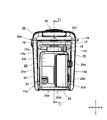
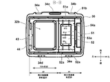
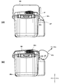
- FIG. 2 is a front view of the cool box 1 which concerns on the Example of this invention. It is a right view of the cool box 1 of FIG.
- FIG. 2 is a right side view of the cool box 1 of FIG. 1, showing a state where a cover 24 of the battery storage chamber 20 is opened.
- FIG. 2 is a cross-sectional view taken along the line AA in FIG. It is the elements on larger scale which show the heat exchange mechanism 50 of FIG.
- FIG. 3 is a cross-sectional view taken along the line BB in FIG.
- FIG. 3 is a DD sectional view of FIG. 2.
- FIG. 2 is a cross-sectional view taken along the line CC of FIG. It is a circuit diagram of cold storage 1 concerning the example of the present invention.
- FIG. 1 is a front view of the cool box 1.
- the cool box 1 is obtained by adding a heat exchange mechanism using electric power to a so-called cooler box type container.
- pack-type batteries 61 and 62 widely used for electric tools (see FIG. 3).
- the cool box 1 has a portable configuration with an internal volume of about 10 to 40 liters, for example, 25 liters.
- a Peltier element is used to enable not only cooling but also heat retention.
- a dedicated cool cooler only for cooling, or a dedicated warm keep box only for warming is used to enable not only cooling but also heat retention.
- a substantially rectangular parallelepiped container portion 10 having an opening on the upper side is provided with a door portion 30 serving as a lid for closing the opening.
- the container part 10 is a substantially rectangular parallelepiped and has a shape in which only one surface (upper surface) is an opening, and four side wall parts (a front wall part 11a, a rear wall part 11b (see FIG. 2)) that define the opening, A wall portion 11c, a left wall portion 11d), and a bottom wall portion 12b which is a surface opposite to the opening of the container portion 10.
- the front wall portion 11a and the rear wall portion 11b are arranged substantially in parallel, and the right wall portion 11c connects the right end edge of the front wall portion 11a and the right end edge of the rear wall portion 11b, and the left wall portion. 11d connects the left end edge of the front wall part 11a and the left end edge of the rear wall part 11b. Further, the upper end portions of the front wall portion 11a, the rear wall portion 11b, the right wall portion 11c, and the left wall portion 11d define an opening that is substantially rectangular in a plan view.
- the opening of the container part 10 is closed by a door part 30 that can be opened and closed with respect to the container part 10.
- the door part 30 is pivotally supported by a hinge 19 (described later in FIG. 4) on one side of the long side of the opening of the container part 10.
- Two latches 18a and 18b are provided in the long side part (here, the upper edge part of the front wall part 11a) on the opposite side to the long side part in which the hinge is provided in the opening of the door part 30.
- the latches 18a and 18b are manually operable lock mechanisms that are fixed to the convex portions 34a and 34b (described later in FIG. 6) formed on the door portion 30 side so as to be hooked on the convex portions formed on the latch 18a and 18b side.
- a known fixing member such as a patchon lock or a latch can be used.
- a convex portion 14 for holding the latches 18 a and 18 b and forming a recess 14 a for putting a hand when the door portion 30 is opened is formed. Since the bottom surface of a part of the outer edge of the door part 30 is exposed above the depression 14a, the outer edge part in front of the door part 30 is easily pulled upward when the latches 18a and 18b are opened. Can do.
- the state of FIG. 1 is in a closed state in which the opening of the container part 10 is closed.
- the opening of the container part 10 is opened, and the stored item can be accommodated in the accommodation space through the opening. Further, since the opening is closed when the door portion 30 is closed, the accommodation space 13 is hermetically sealed, and heat exchange due to direct contact between the inside and outside air is minimized.
- a first grip 16 is formed on the left side of the opening of the container 10.
- a second grip 17 is formed on the right side of the opening of the container 10.
- the first gripping portion 16 and the second gripping portion 17 are convex portions that are formed to carry while gripping the vicinity of the opposing short sides of the cool box 1 with both hands. It is provided near the upper part of the wall 11d.
- the 1st holding part 16 and the 2nd holding part 17 are shape
- recessed portions 16 a and 17 a are formed to make it easier for an operator to hold with both hands.
- a through-hole (not shown) for penetrating the shoulder belt 65 from the top to the bottom is formed near the center in the front-rear direction of the recessed portions 16a and 17b.
- the first gripping portion 16 in which the through hole is formed becomes the first belt attaching portion
- the second gripping portion 17 in which the through hole is formed becomes the second belt attaching portion.
- a single belt-like shoulder belt 65 is stretched between the first belt attachment portion and the second belt attachment portion.
- the belt adjusters 66 and 67 are members that fold both ends of the shoulder belt 65 and pass through the overlapped portions, thereby fixing the stacked belts so as not to move relative to each other and adjusting the effective length used for the shoulder straps. is there.
- the belt adjusters 66 and 67 are integrally formed plastic or metal parts, and are formed by connecting three parallel elongated long plate-like ends at orthogonal connecting portions. Two E-shaped members are prepared, and the shape is such that the opening sides face each other and are joined. When the belt adjusters 66 and 67 are made of synthetic resin, sufficient strength is provided.
- the shoulder belt 65 is provided with a shoulder pad 68 for dispersing a local load applied to the operator's shoulder when shouldering.
- a well-known shoulder pad 68 can be used, and the shape and material of the shoulder pad 68 are arbitrary.
- a pair of casters 88 a is provided near the left end of the bottom wall portion 12 b of the container portion 10.
- casters 88b (not visible in FIG. 1) are provided in the vicinity of the corners of the rear wall portion, the left wall portion 11d, and the bottom wall portion 12b, and the casters 88a are pivotally supported by the container portion 10 and have a rotation shaft 89a. Facing forward and backward.
- the rotation axis of the rear caster 88b is positioned coaxially with the rotation axis 89a, and the axial direction thereof is the front-rear direction. In the state where the container part 10 is kept horizontal as shown in FIG.
- the casters 88a and 88b are not substantially operated even when the casters 88a and 88b are installed, and the container part 10 is inclined.
- the casters 88a and 88b can be operated.
- the state in which the casters 88a and 88b do not substantially operate means that the movement of the container portion 10 in the horizontal direction is limited by the grounding of the lower surface of the bottom wall portion 12b on the opposite side of the casters 88a and 88b. Includes state.
- a battery housing chamber 20 having a second rectangular parallelepiped housing is provided on the right wall portion 11c of the container portion 10.
- the housing volume of the battery housing chamber 20 is configured to be sufficiently smaller than the housing volume of the container unit 10.
- the battery housing chamber 20 is an independent space for housing two batteries (described later) and a control circuit board (described later). If the outer wall of the container part 10 and the outer wall of the battery storage chamber 20 are manufactured by integral molding of synthetic resin, the strength can be sufficiently increased.
- the container part 10 as a container of a cool box and the battery storage chamber 20 for storing a power source part such as a battery (not shown) are configured in separate sections, the internal space of the container part 10 is used for mounting the battery. The limited space can be effectively utilized without being pressed.
- the door part 30 that can be opened and closed is provided with a heat exchange mechanism 50 (described later in FIG. 5) using a Peltier element.
- the container part 10 is not provided with any main component of the heat exchange mechanism such as a fan or a heat sink. Since the heat exchange mechanism is provided, an intake port 35 of an outer fan, which will be described later, is provided in a part on the upper side of the door part 30, and an exhaust port 36 is provided in a part of the front side surface of the door part 30. Although not visible in FIG. 1, an exhaust port similar to the front exhaust port 36 is also provided on a part of the rear side surface of the door portion 30. The air sucked into the door portion 30 from the intake port 35 is exhausted from the front exhaust port 36 and the rear exhaust port (not visible in FIG. 1).
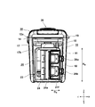
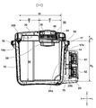
- FIG. 2 is a right side view of the cool box 1.
- the door portion 30 has substantially the same appearance as the door portion of a commercially available cooler box, except that the upper portion has an intake port 35 and an exhaust port 36 (see FIG. 1). However, since the heat exchange mechanism is accommodated in the door portion 30, the height of the door portion 30 in the vertical direction is increased.
- the battery storage chamber 20 disposed on the right side of the container unit 10 is a casing that is smaller in the vertical direction and the front-rear direction than the outer casing of the container unit 10.
- the front wall portion 21a, the rear wall portion 21b, the upper side wall 21c, and the lower side wall 21d of the battery storage chamber 20 are connected so that there is no gap between the right wall portion 11c and the joint portion of the container portion 10.
- An opening 21f (see FIG. 3 described later) is provided on the rear side of the front-rear direction central plane (DD cross section) of the battery storage chamber 20, and an openable cover 24 is provided to cover the opening 21f.
- the cover 24 is formed so as to extend over two surfaces from the right wall portion 21e to the rear wall portion 21b of the battery storage chamber 20, and is supported by a rotating shaft 24a whose axis extends in the vertical direction at the front side edge portion.
- the closed state is locked by two latch means, namely the first latch 26a and the second latch 26b.
- the latch means for example, a resin-made patch-on lock in which a movable claw portion is engaged with a convex hook portion formed on the cover 24 side can be used.
- the first latch 26a is illustrated in an unlocked state and the second latch 26b is illustrated in a locked state for the sake of explanation.
- a power jack cover 23 that covers an opening for access to a power jack 71 for connecting a power cord, which will be described later, is formed on a part of the battery housing chamber 20 on the lower side on the front side.
- the power jack cover 23 is a plate-shaped lid that is pivotally supported on one side and has a lock mechanism on the opposite side.
- An operation display panel (not shown) is provided in a partial region 22 on the outer surface of the battery storage chamber 20.
- the operation display panel is provided with a power switch (not shown), various operation buttons (cooling / heating switching, output mode setting), a display lamp indicating an operating state, and the like.
- a flange-shaped second gripping portion 17 that protrudes outward in the horizontal direction is formed on the outer edge portion near the opening 12 a at the upper end of the container portion 10.
- the second gripping portion 17 serves as a handle for the user to grip with both hands together with the first gripping portion 16, and has a sufficient length in the front-rear direction compared to the user's hand, so that the user can easily put his / her finger.
- a through hole (second belt attaching portion 17b) that penetrates from the top to the bottom of the second gripping portion 17 in order to allow the shoulder belt 65 to penetrate in the vicinity of the center in the front-rear direction of the concave portion 17a. Is formed.
- the cross-sectional shape of the through-hole is a long and narrow quadrilateral, and the width WB (length in the long side direction) of the through-hole serving as the second belt mounting portion 17b is slightly larger than the width of the belt-shaped shoulder belt 65, By making the length of the short side larger than the thickness of the shoulder belt 65, the shoulder belt 65 that penetrates can be easily moved relative to the through hole.
- a cord housing convex portion 15 that is elongated and projects outward from the second gripping portion 17 to the upper side wall 21c of the battery housing chamber 20 is formed.
- the cord accommodating convex portion 15 is formed to secure a space for wiring in the inner portion thereof.
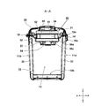
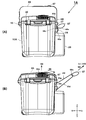
- FIG. 3 shows a state where the cover 24 is opened from the state of FIG.
- the cover 24 can be rotated about 180 degrees around the rotation shaft 24a.
- the rotation shaft 24a is arranged to extend in the vertical direction (up and down direction). If the axial direction (front-rear direction) of the rotation shaft 89a of the casters 88a, 88b is parallel to the axial direction (vertical direction) of the rotation shaft 24a, vibrations generated around the rotation shaft 89a of the casters 88a, 88b. Since the direction of the rotation axis of the cover 24 is the same as that of the cover 24, the force to open the cover 24 repeatedly acts, and the load applied to the first latch 26a, the second latch 26b, and the rotation shaft 24a increases. .
- the vibration direction generated around the casters 88a and 88b intersects the axial direction of the rotating shaft 24a, so that the cover 24 is caused by vibration. It can suppress that force is applied to the direction which tries to open.
- Two batteries 61 and 62 are arranged side by side so that the mounting surface on which the connection terminals are arranged faces in the vertical direction.
- the mounting direction is from the rear to the front side of the battery housing chamber 20, and is mounted by moving the batteries 61 and 62 from the rear to the front in a state where the batteries 61 and 62 are laid down.
- the length in the front-rear direction of the opening 21f is approximately half the length DB of the batteries 61 and 62 to be accommodated.
- This length DB is set to a length that does not hinder the user's operation of pressing a latch button (not shown) of the batteries 61 and 62 in a state where the battery is installed in the battery storage chamber 20.
- the height HB of the storage space inside the battery storage chamber 20 is not less than the size of two batteries so that the user can press the latch buttons and pull out the batteries 61 and 62. Therefore, the battery 61 and 62 are sized so as to secure a predetermined space around them.
- the height HB of the accommodating space is made substantially equal to the height of the opening 21f.
- the battery accommodating chamber 20 can accommodate a plurality of batteries and the opening (opening) is provided with a lid (cover 24) that can be opened and closed, the accommodating space of the battery accommodating chamber 20 can be sealed.
- the circuit board and the like can be completely covered, and can be protected from intrusion of dust and rainwater.
- the accommodation space 13 is a space for storing an article, and is an inner surface of a surrounding wall (the rear surface of the front wall portion 11a, the front surface of the rear wall portion 11b, the left surface of the right wall portion 11c, and the right surface and bottom of the left wall portion 11d). Defined by the upper surface of the wall 12b.
- the outer surface and the inner surface of the wall portion of the container portion 10 are made of, for example, ABS resin, and a heat insulating material 33 such as urethane foam is filled between the outer surface and the inner surface, thereby ensuring the heat insulation in the accommodation space 13. .
- the door part 30 is provided with an outer wall 31 and an inner wall 32.
- a heat exchange mechanism 50 is provided inside the door unit 30.
- the heat exchange mechanism 50 is a cooling or heating device that takes heat in the accommodation space 13 and discharges it into the atmosphere, or absorbs heat in the atmosphere and releases it into the accommodation space 13.
- the heat exchange mechanism 50 includes two Peltier elements 51 and 52, an outer heat sink 54 and an outer fan 55 disposed on the front surface side (outer surface side) of the Peltier elements 51 and 52, and the rear surface side (inner surface) of the Peltier elements 51 and 52.
- the inner heat sink 56 (56a to 56c) and the internal fan 57 are mainly configured.
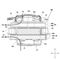
- FIG. 5 is a partially enlarged view showing the heat exchange mechanism 50 of FIG. A through hole 32 a for providing a heat exchange mechanism is formed in the inner wall 32 of the door portion 30.
- Peltier elements 51 and 52 are arranged adjacent to each other so as to have a slight gap 53a in the front-rear direction so as to be parallel to the surface direction of inner wall 32.
- the upper surfaces of the Peltier elements 51 and 52 are in contact with the outer heat sink 54 in common, and the lower surfaces are in contact with the heat conductor 56 a of the inner heat sink 56 in common.
- Each of the Peltier elements 51 and 52 is connected to a red cord and a black cord, which will be described later, and when an electric current flows from the red cord to the black cord, the upper surface generates heat and the lower surface absorbs heat (the lower surface is cooled). On the other hand, when the current flows from the black cord to the red cord, the upper surface absorbs heat and the lower surface generates heat.
- the heat conductor 56a is an aluminum block, for example, and is formed in a size corresponding to the through hole 32a.
- the gap 32c between the through hole 32a and the heat conductor 56a is provided, but the gap 32c may be filled with an adhesive resin.
- the outer heat sink 54 is formed by a plate-like base portion 54a that is in contact with the upper surface of the Peltier elements 51 and 52, and a fin portion 54b that is composed of a plurality of plate-like fins extending upward in the orthogonal direction from the base portion 54a. .
- the fin portion 54b extends in the front-rear direction and has a predetermined length in the up-down direction, and the outer heat sink 54 is manufactured by integral molding of a light metal such as aluminum.
- An elastic body 58 such as rubber is interposed between the base portion 54 a of the outer heat sink 54 and the inner wall 32.
- An outer fan 55 is provided adjacent to the upper side of the fin portion 54b.
- the outer fan 55 is a centrifugal fan, and by rotating the outer fan 55, outside air is sucked in the axial direction (from the top to the bottom) from the plurality of slits 35a formed in the air inlet 35, and the radial direction as indicated by the arrow AF1. And exhausted from the exhaust port 36 (see FIG. 1). At this time, the outside air is brought into contact with the heated outer heat sink 54 to take heat away from the outer heat sink 54.
- the arrow AF1 is shown to flow from the top to the rear, but an air flow that flows from the top to the front is generated in the same manner on the Peltier element 52 side.
- the inner heat sink 56 includes a heat conductor 56a, a base portion 56b, and a fin portion 56c, which are manufactured by integral molding of a light metal such as aluminum.
- a plate-like base portion 56b having a large area is connected to the lower surface of the heat conductor 56a, and a plurality of plate-like fins extending in the orthogonal direction from the base portion 56b are provided below the plate-like base portion 56b.
- a fin portion 56c is formed.
- the fin portion 56c extends in the front-rear direction and has a predetermined length in the up-down direction.
- An internal fan 57 is formed adjacent to the lower portion of the fin portion 56c.
- a fan cover 37 made of synthetic resin in which a plurality of wind windows (here, invisible due to the cross-sectional shape) are formed.
- the internal fan 57 is close to the fin portion 56c, sucks air from the upper surface in the internal space of the container portion 10 from below in the axial direction, and flows the air to the fin portion 56c sufficiently so as to be radially outward. Then, it is discharged as indicated by an arrow AF2.
- FIG. 5 only the component of the air flow AF ⁇ b> 2 directed backward is indicated by an arrow, but is similarly discharged to the front side by the inner heat sink 56.
- the cooled inner heat sink 56 removes heat from the flowing air as in AF 2, so that the temperature inside the box is lowered.
- the air in the warehouse is sufficiently agitated by circulating the air as indicated by the arrow AF2.
- the outer edge shape of the door portion 30 is substantially rectangular in a bottom view or a top view, and convex portions 34a and 34e that engage with the latches 18a and 18b are formed on one side (front side) of the long side of the outer edge. Further, in the vicinity of the center between the convex portions 34 a and 34 b, a slight recess 34 c is formed for the user to put on his hand when opening the door portion 30. Attachment portions 34d and 34c for fixing the hinge 19 are provided on the other side (rear side) of the long side of the outer edge.
- a substantially half on the left side is formed with a concave portion 32 b that is recessed upward, and a substantially half on the right side is the arrangement portion 41 of the heat exchange mechanism 50.
- a rotating stopper piece 43 is provided on the left side of the recess 32b so as to maintain an open state with a predetermined angle when the door 30 is opened.
- the stopper piece 43 is pivotally supported on the door portion 30 via the rotating shaft 44 in the rear, the front side 43a becomes a free end portion, and comes into contact with the upper surface near the opening of the container portion 10 so that the door portion 30 is slightly Can be held open.
- the cross-sectional position in FIG. 6 is at the same position as the lower surfaces of the two Peltier elements 51 and 52.
- the Peltier elements 51 and 52 have the same size and the same standard, and are adjacent to each other with a slight gap 53a.
- the size of the base portion 54 a of the outer heat sink 54 is configured to be larger than the combined size of the two Peltier elements 51 and 52.
- the red cord 51a and the black cord 51b are drawn forward from the Peltier element 51, and the red cord 52a and the black cord 52b are drawn backward from the Peltier element 52.
- the drawn power cords (51a, 51b, 52a, 52b) are wired to the control circuit board 70 of the battery housing chamber 20 through the cord housing projection 15 (see FIG. 2).
- the direction of the cord drawn from the Peltier elements 51 and 52 is directed not to the side (right side) but to the front side or the rear side, thereby reducing the space required for wiring and
- the size in the left-right direction occupied by the placement portion 41 was set to be equal to or less than the size in the left-right direction occupied by the non-placement portion 42 of the heat conversion mechanism.
- the configuration of this embodiment is a configuration in which the conventional door portion 130 is replaced with the door portion 30 shown in FIG. In the conventional door part 130, only one Peltier element 151 is provided.
- the size of the outer heat sink 154 in contact with the Peltier element 151 was also a size corresponding to one Peltier element 151.
- the red cord 151a and the black cord 151b are arranged to be pulled out to the right side for wiring with the control circuit board provided in the battery housing chamber 20.
- the two Peltier elements 151 are adjacent to each other in the front-rear direction, and the red cord 151a and the black cord 151b are routed to the right from each Peltier element 151.
- a space for routing the red cord 151a and the black cord 151b is required in the same manner as in the example of FIG. 19, so that the lateral width indicated by A1 is required to some extent, and the length B1 of the recess 132b is shortened.
- the side 51d opposite to the side 51c from which the red cord 51a of the Peltier element 51 and the black cord 51b are drawn is arranged with the red cord 52a of the Peltier element 52, as shown in FIG.
- the gaps 53a are arranged so as to be adjacent to the side portions 52d facing each other as viewed from the side portions 52c from which the black cords 52b are drawn.
- the direction of the power cord drawn from the Peltier elements 51 and 52 is not directed to the side (right side), the positions of the Peltier elements 51 and 52 are shifted to the right side of the conventional example shown in FIG.
- the red cords 51a and 52a and the black cords 51b and 52b can be prevented from becoming long.
- FIG. 7 is a sectional view taken along the line DD of FIG.
- the inner width of the container part 10 is W
- the distance between the side where the heat exchange mechanism 50 is accommodated and the side where it is not accommodated is approximately equal to W / 2.
- Battery mounting portions 25a and 25b are arranged in the battery storage chamber 20 in the vertical direction.
- the battery mounting portions 25a and 25b have connection terminal portions (not shown) and are connected to connection terminals (not shown) formed on the batteries 61 and 62 side.
- a set of guide rails (not shown) extending in parallel with each other are formed on the battery mounting portions 25a and 25b.
- a control circuit board 70 is disposed in a portion of the battery housing chamber 20 closer to the container portion 10 than the batteries 61 and 62.
- the control circuit board 70 is arranged so that its surface direction is vertical, and includes a power cord to the Peltier elements 51 and 52, a power cord to the outer fan 55, a power cord to the internal fan 57, and a temperature sensor 78 (FIG.
- a cord group 59 including a signal line and the like to 9) is wired to the door portion 30.
- FIG. 8 is a cross-sectional view taken along the line CC of FIG.
- the two batteries 61 and 62 are arranged side by side at a predetermined distance.
- the sliding direction for mounting the batteries 61 and 62 is from the rear to the front (horizontal direction), and the direction is parallel to the axial direction of the rotation shaft 89a of the casters 88a and 88b.
- a control circuit board 70 is provided in front of the batteries 61 and 62.
- the control circuit board 70 is provided with a power supply connection portion for enabling connection to an external power supply other than the batteries 61 and 62, that is, a power supply jack 71.
- the power jack 71 has a terminal 85b that can be connected to the power jack 71 at one end and a cigar socket 85a at the other end as shown in FIG.
- an AC-DC conversion adapter 86 can be connected for conversion from an AC power source to a DC power source.
- the AC-DC conversion adapter 86 includes an outlet 86 a that is connected to a commercial power source for home use (for example, AC 100 V), an adapter unit 86 b that accommodates the AC-DC converter, and a terminal 86 c that can be connected to the power jack 71.
- the device shown in FIG. 9 is housed in the housing of the battery housing chamber 20 except for the Peltier elements 51 and 52, and the microcomputer 77 and the electric circuit portion are mainly mounted on the control circuit board 70 (see FIG. 8). .
- the cool box 1 supplies a predetermined direct current to two Peltier elements 51 and 52 using a power source, thereby absorbing one surface of the Peltier elements 51 and 52 and generating heat on the opposite surface.
- the amount of heat absorbed by the Peltier elements 51 and 52 is almost proportional to the magnitude of the applied voltage (V). However, if the applied voltage is too large, the amount of heat generation increases and the cooling efficiency decreases, so about 50-60% of the maximum voltage. The efficiency of.
- the driving of the Peltier elements 51 and 52 and the driving of the fans 55 and 57 are controlled by the microcomputer 77.
- the microcomputer 77 controls the operation of the cool box 1, and uses a commercially available one-chip type microcontroller (microcontroller). Although the microcomputer 77 operates at a voltage of 5 V or 3.3 V, a power supply circuit for the microcomputer 77 is not shown in FIG.
- the power source for the microcomputer 77 may be generated using a DC-DC converter such as a three-terminal regulator circuit using the power of the batteries 61 and 62.
- the power source of the cool box 1 is a three power source system.
- One is the batteries 61 and 62 arranged in the battery storage chamber 20.
- the cool box 1 can be operated even in an environment where a commercial power source or an in-vehicle power source cannot be obtained.
- two detachable batteries can be mounted.
- a connection method of switching them for control, connecting them in series, or connecting them in parallel is possible.
- a switching control method is adopted, and in the case of battery drive, the microcomputer 77 selects and uses either the battery 61 or the battery 62 in order.
- the batteries 61 and 62 are connected in parallel to the Peltier elements 51 and 52 serving as loads, and relay switches 75 and 76 are provided respectively.
- diodes D1 and D2 are provided so that current does not circulate between the batteries 61 and 62.
- the relay switches 75 and 76 are controlled to be opened and closed by the microcomputer 77.
- the microcomputer 77 measures, for example, (1) the order in which the battery 61 is first used and then the battery 62, and (2) the respective voltages of the batteries 61 and 62 in accordance with a predetermined rule.
- the order of use from the battery side with a high remaining amount or the battery side with a low remaining amount can be selected.
- not only battery packs of the same standard but also batteries with different rated voltages can be mixed and installed as the batteries 61 and 62.
- a battery with a rating of 14.4 V may be used as the battery 61
- a battery with a rating of 18 V may be used as the battery 62.
- a plurality of types of batteries can be directly connected to the battery mounting portions 25a and 25b (see FIG. 7) or conversion adapters. It is preferable to be configured so that it can be mounted via the.
- Batteries 61 and 62 contain a plurality of secondary battery cells.
- a lithium ion secondary battery is used.
- the batteries 61 and 62 include a temperature signal output terminal in addition to a power supply connection terminal such as a charge plus terminal (C +), a discharge plus terminal (+), and a charge / discharge minus terminal ( ⁇ ).
- C + charge plus terminal
- + discharge plus terminal
- ⁇ charge / discharge minus terminal
- T overcharge signal output terminal
- Vs battery type discrimination terminal
- LD remaining battery level signal output terminal
- a part is connected to the microcomputer 77. Accordingly, the microcomputer 77 can detect the type and remaining amount of the batteries 61 and 62.
- the DC-DC converter 80 serving as the first power supply unit supplies driving direct current to the Peltier elements 51 and 52.
- a voltage of 12 V or 6 V is generated from a battery of 14.4 V, 18 V, or 12 V or more and supplied to the Peltier elements 51 and 52.
- the “Peltier element” is called an electronic cooling element, and can cool one side using the principle that heat is transferred between metals by joining different metals and passing an electric current therethrough.
- Peltier elements have no moving parts, so they have excellent durability and reliability, and are easy to handle. Further, there is no risk of refrigerant gas leakage and corrosion, and handling is easy. Furthermore, the Peltier element can reverse the warming surface and the cooling surface by reversing the voltage polarity (plus, minus) to be applied.
- the polarities flowing in the Peltier elements 51 and 52 are illustrated as being fixed. However, by interposing a switching circuit (not shown) that reverses the polarity, the whole structure of the cool box 1 can be kept warm without changing. It can also be used as a storage.
- switching elements M6 and M7 such as FET (Field Effect Transistor) are interposed.
- a control signal from the microcomputer 77 is input to the gates of the switching elements M6 and M7, and the microcomputer 77 blocks either or both of the switching elements M6 and M7, so that both of the Peltier elements 51 and 52 or One operation can be stopped.
- a resistor 1 and resistors R3 to R5 are circuits for setting a feedback voltage (feedback voltage) FB to the DC-DC converter 80, and semiconductor switching elements M3 to M5 are directly provided in the resistors R3 to R5, respectively.
- the outputs of the microcomputer 77 are connected to the gates of the semiconductor switching elements M3 to M5, and can be connected or disconnected under the control of the microcomputer 77.
- the feedback voltage (feedback voltage) to the DC-DC converter 80 is changed by a combination of connection or cutoff of the switching elements M3 to M5, and the output voltage from the DC-DC converter 80 to the Peltier elements 51 and 52 can be changed. is there.
- DC-DC converters 81 and 82 serving as a second power supply unit are provided.
- the DC-DC converter 81 is a power source for driving the outer fan 55.
- the DC-DC converter 82 is a fan for driving the internal fan 57.
- a switching element M1 is interposed in power supply to the outer fan 55, and a semiconductor switching element M2 is interposed in power supply to the internal fan 57.
- the switching elements M1 and M2 can be controlled on and off by the microcomputer 77.
- the charging circuit 72 When input is made via a commercial power supply or an external DC power supply via a power supply jack 71 serving as an external power supply connection portion, the charging circuit 72 operates.
- the output of the charging circuit 72 is connected to the batteries 61 and 62 and also connected to the DC-DC converters 80 to 82 via the relay switches 75 and 76. Accordingly, power can be supplied to the DC-DC converters 80 to 82 and the batteries 61 and 62 can be charged.
- a charge control circuit 73 is provided to control charging of the batteries 61 and 62.
- the microcomputer 77 detects whether or not an external power source is connected by the input detection circuit 74 and outputs it to the microcomputer 77.
- the microcomputer 77 controls the charge control circuit 73 by this output.
- the microcomputer 77 can detect the temperature in the cabinet.
- the microcomputer 77 optimizes the power supplied to the Peltier elements 51 and 52 based on the battery mounting state (one or two), the connection state with the external power source, and the internal temperature (temperature in the accommodation space 13). To control.
- the outer fan 55 and the internal fan 57 can be operated continuously regardless of the operation status of the Peltier elements 51 and 52, the operation of the heat exchange mechanism 50 and the operation of the external fan 55 and the internal fan 57 are performed. Can be controlled independently, and efficient operation is possible even with limited power from the batteries 61 and 62.
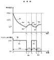
- FIG. 10 is a diagram for explaining the control method of the Peltier element 151 in the conventional example.
- the upper graph shows the relationship between the passage of time (unit: minutes) and the internal temperature (unit: ° C.), and the lower graph shows The relationship between the passage of time (unit: minute) and the supply voltage (unit: V) to the Peltier element 151 is shown.
- the horizontal axes of the upper and lower graphs are shown together.
- the voltage 92 applied to the Peltier element 151 so far is constant at 12 V, and the voltage supply to the Peltier element 151 is stopped at time t1 (the voltage is set to 0 as indicated by the arrow 92b).
- the internal temperature gradually rises as indicated by an arrow 91c.
- 12V is applied to the Peltier element 151 as indicated by an arrow 92c.
- the internal temperature decreases as indicated by an arrow 91e.
- the ON / OFF control of the Peltier element 151 is repeated at times t1 to t3.
- the conventional cool box since a common power supply circuit is used for the Peltier element 151, the outside fan, and the internal fan, voltage switching of only the Peltier element 151 cannot be performed.
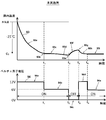
- FIG. 11 is a diagram illustrating a method for controlling the Peltier elements 51 and 52 in the present embodiment.
- the upper graph in FIG. 11 shows the relationship between the passage of time (unit: minutes) and the internal temperature (unit: ° C.), and the lower graph shows the passage of time (unit: minutes) and the voltage supplied to the Peltier element (unit: minutes).
- the relationship of unit: V) is shown.
- the temperature is lowered to 25 ° C. lower than the outside air temperature C2 (where C2 ⁇ C1).
- the temperatures C1 and C2 are controlled so as not to reach a predetermined temperature (for example, less than 5 ° C.).
- the temperature C2 is a set value when the cooling mode is “strong”, and the set temperature difference is set small when “medium” or “small” is set.
- the internal temperature 93 decreases as indicated by an arrow 93a and reaches a desired temperature C2 (here, a temperature 25 ° C. lower than the outside temperature) as indicated by an arrow 93b at time t1.
- a desired temperature C2 here, a temperature 25 ° C. lower than the outside temperature
- the voltage 93 applied to the Peltier elements 51 and 52 so far is constant at 12V, and at time t1, the voltage to the Peltier elements 51 and 52 is reduced from 12V as indicated by the arrow 94a to 6V as indicated by the arrow 94b.
- This 6V generation may be achieved by reducing the output of the DC-DC converter 80 itself or by reducing the effective value of the voltage to 6V by PWM control of the switching elements M6 and M7 (see FIG.
- the microcomputer 77 stops supplying voltage to the Peltier elements 51 and 52 as indicated by an arrow 94c. To do. Then, with the passage of time, the internal temperature 93 rises as indicated by an arrow 93f, but when the temperature reaches a predetermined threshold value, that is, a temperature at which power supply to the Peltier element is resumed as indicated by an arrow 93g, an arrow 94d Thus, 12V is applied to the Peltier elements 51 and 52. At this time, instead of supplying 12V to the Peltier elements 51 and 52, 6V may be applied.
- the microcomputer 77 decides which one to use, considering the rising speed of the arrow 93f. good.
- the internal temperature gradually decreases as indicated by an arrow 93h.
- a predetermined threshold value that is, a threshold temperature for reducing the power of the Peltier elements 51 and 52
- the voltage to the Peltier element is reduced to 6V as indicated by an arrow 94e. Thereafter, the same control is repeated.
- the portable cool box 1 is operated using two Peltier elements 51 and 52 while switching between multiple voltages (12V and 6V). Compared to, the cooling performance was significantly improved. In addition, since a large driving time is secured in a voltage region where the cooling efficiency of the Peltier element is the best, that is, a driving voltage of 50 to 60% of the maximum allowable voltage, an increase in overall power consumption can be avoided.
- a large driving time is secured in a voltage region where the cooling efficiency of the Peltier element is the best, that is, a driving voltage of 50 to 60% of the maximum allowable voltage, an increase in overall power consumption can be avoided.
- only the cooling mode in which the upper surface of the Peltier elements 51 and 52 generates heat and the lower surface absorbs heat when electric power is supplied to the Peltier elements 51 and 52 has been described.
- the operation in the heat-retaining mode in which the upper surface is cooled and the lower surface is heated can be controlled in the same manner.
- a part of the shoulder belt 65 (in the vicinity of the arrow 65c) in the cool box 1 is pulled out from the second belt mounting portion 17b, and the cool box 1 is rolled using the casters 88a and 88b.
- a state (2nd attachment state) is shown.
- the grip 69 is held at a position in contact with the second gripping portion 17 when the first mounting state is restored, the grip 69 is removed when the operator moves the cooler 1 in a shouldered state. There is no risk of getting stuck or getting in the way.
- the shoulder belt can be changed to the second attachment state as shown in FIG. 12 even when the shoulder pad 68 is attached.
- FIG. 12 shows a state where the grip 69 is gripped and the right side of the container part 10 is slightly lifted counterclockwise.
- the centers of swinging at this time are the pivot shafts 89a and 89b of the casters 88a and 88b.
- the caster 88b and its rotating shaft 89b are not visible, but the caster 88b and its rotating shaft 89b are located at the same position when seen through the caster 88a from the front.
- vibration due to the unevenness of the ground is transmitted through the casters 88a and 88b, and the vibration direction is the vertical direction of the container portion 1 in substantially the same manner as the swinging direction.
- batteries 61 and 62 having a large weight are mounted inside the battery housing chamber 20.
- the relationship between the mounting direction of the batteries 61 and 62 (the longitudinal direction of the mounting rail portion) and the axial direction of the rotation shafts 89a and 89b of the casters 88a and 88b is parallel.
- the vibrations transmitted to 62 tilt direction in FIG. 12
- the component component acting in the direction of removing the batteries 61 and 62 can be greatly reduced.
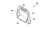
- FIG. 13 is a view showing a specific shape of the grip 69 used as the drawing ring shown in FIG.
- the grip 69 is manufactured by integral molding of a synthetic resin, and a belt holding portion 69c in which a cylindrical holding portion 69a for an operator to hold and a through hole 69d for allowing the shoulder belt 65 to pass therethrough are formed. And a connecting portion 69e that connects the belt holding portion 69c at both ends of the gripping portion 69a.
- the opening 69b surrounded by the gripping portion 69a, the belt holding portion 69c, and the connecting portion 69e has a size that allows an operator to pass four fingers from the index finger to the little finger.
- the belt holding portion 69c is a holding portion that allows the shoulder belt 65 to penetrate from one side to the other side through the through hole 69d, has a lateral width sufficiently larger than the lateral width of the shoulder belt 65, and is a tensile load applied to the opening 69b. Ensures sufficient strength to withstand. Further, it is important that the shoulder belt 65 and the through hole 69d can be easily slid, and the corner portions are formed with gentle curved surfaces so that the shoulder belt 65 does not hurt when sliding.
- FIG. 14 is a diagram showing the grip 69 alone, (A) is a front view, (B) is a top view, and (C) is a left side view.
- the holding portion 69a has a width that is optimal for holding with one hand.
- the grip portion 69a since it is a figure of the grip 69, the state when not in use is shown, and the direction is shown on the right side. In actual use, the user grips the grip portion 69a and moves the vicinity of the arrow 65c of the shoulder belt 65 (see FIG. 12) upward through the through hole 69d.
- the hand is made to be slippery and the surface can be gripped in a comfortable state for the operator.
- a soft layer is formed.
- FIG. 14B is a top view of the grip 69, and it can be understood that the belt holding portion 69c is sufficiently thinner than the gripping portion 69a when viewed together with the left side view of FIG. 14C.
- the shoulder belt 65 passes through the belt holding portion 69c from one side to the other side.
- the gripping portion 69a obliquely upward in this state, the shoulder belt 65 is pulled upward as indicated by an arrow 65c shown in FIG.
- the shape of the grip 69 has been described with reference to FIGS. 13 and 14.
- the shape of the grip 69 has a high degree of freedom in design, and other shapes can be used as long as there is a through hole 69d that allows the grip portion 69a and the belt to pass therethrough. good.
- the material of the grip 69 is not limited to the synthetic resin, but may be made of cloth, leather, metal frame, other materials, or a combination thereof.
- the grip 69 is not always fixed to the shoulder belt 65, but a cantilever hook is formed instead of the through hole 69d so that the grip 69 can be easily attached to or detached from the shoulder belt 65. good.
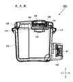
- the third belt attaching portion 27 is a convex portion provided on the upper portion of the battery accommodating chamber 20 and protruding upward, and penetrates from the left to the right in the horizontal direction in the vicinity of the center in the front-rear direction of the convex portion. A hole was formed.
- FIG. 15 shows that a portion of the shoulder belt 65 that extends to the outer peripheral side (right side) of the second gripping portion 17 is pulled out downward, and the pulled-out portion is a through hole of the third belt mounting portion 27 of the battery storage chamber 20.
- FIG. 15 shows this pulled out state.
- the shoulder belt 65 passes through the second belt mounting portion 17b of the second gripping portion 17 and passes through the through hole of the third belt mounting portion 27 as indicated by an arrow 68b, and the arrows 68c and 68d. , 68e, loops through the third belt mounting portion 27 from right to left again, and is connected to the belt adjuster 67 from the third belt mounting portion 27 as indicated by an arrow 68f.
- the arrow 68c to 68e portion of the shoulder belt 65 functions as a pull string, so the user lifts the battery storage chamber 20 side above the ground by gripping the vicinity of the arrow 68d of the shoulder belt 65. The state can be pulled to the right.
- the shoulder belt 65 is left as it is with the battery storage chamber 20 side floating above the ground.
- the casters 88a and 88b By pulling in the right direction, it becomes possible to move in the right direction using the casters 88a and 88b.
- vibration is transmitted from the container unit 10 to the door unit 30 and easily transmitted to the door unit 30 according to the unevenness of the ground.
- the vibration direction generated around the rotation axis of the caster and the door Since the rotation directions are the same, the force for opening the door portion 30 repeatedly acts, and the load on the rotation shafts of the latches 18a and 18b and the hinge 19 increases.
- positions so that the axial direction (front-back direction) of the casters 88a and 88b and the rotational-axis direction (left-right direction) of the hinge 19 of the door part 30 may cross
- the third belt attaching portion 27 is provided on the upper surface of the battery accommodating chamber 20, and the shoulder belt 65 is pulled out and penetrated through the third belt attaching portion 27, whereby the casters 88a and 88b are connected.
- a rotary caster it is possible to easily perform a caster movement that moves as if rolling the ground.
- the shoulder belt 65 is disposed along the upper surface of the door portion 30, so that the force to open the door portion 30 can be suppressed. It becomes possible.
- the shoulder belt 65 always works to hold down the upper surface of the door part 30, so that vibrations to the components provided in the door part 30 are prevented. Is also suppressed. Furthermore, since the third belt attaching portion 27 is located away from the casters 88a, the amount of vertical swing of the container portion 10 can be reduced compared to the example of FIG.
- the portion around the arrows 68c to 68e of the shoulder belt 65 passes through the third belt attaching portion 27 by pulling the vicinity of the arrow 68f upward.
- the hole may be passed through from the right side to the left side.
- the diameter of the outer fan 55 is sufficiently larger than the width of the shoulder belt 65, and the spread of the wind window of the air inlet 35 is sufficiently larger than the width of the shoulder belt 65, so that the shoulder belt 65 completely blocks the air inlet 35. There is no. Accordingly, even when the cooler is maintained by battery driving when the caster is moved, it is possible to prevent the air suction through the air inlet 35 from being affected.
- a part of the shoulder belt 65 pulled out from the second belt attaching portion 17b is passed through and locked, so that it can be used as a caster system in addition to the conventional shoulder belt system. It becomes. Moreover, since it is not necessary to provide a dedicated gripping part for moving the casters, it is possible to avoid an increase in the size of the cool box 1 due to the installation of the gripping part. In addition, since the caster can be moved, it is easy to move on a flat ground such as asphalt, so that it is possible to realize a cool box with improved convenience.
- the mounting portions for the batteries 61 and 62 are separated from the casters 88a and 88b that are vibration sources when the casters are used, vibrations generated between the battery and the battery housing chamber (battery attaching / detaching portion) can be reduced.
- the third belt attaching portion 27 is provided as shown in FIG. 15, not only the caster movement mode (second attachment state) is brought about by drawing the shoulder belt 65 as shown in FIG. 15, but also the third belt attaching portion. It is also possible to adopt a structure in which an independent traction belt is provided at 27.
- FIG. 16 is a modification of the example of FIG.
- the belt is routed when the shoulder strap is moved and when the caster is moved.
- the shoulder belt 65 is attached to the third belt mounting portion 27.
- the belt adjuster 67 is connected outside the third belt attaching portion 27 and the second gripping portion 17.
- the shoulder belt 65 By passing the shoulder belt 65 through the third belt attaching portion 27 in advance as described above, it can be used as shown in FIG. 16A when shouldering, and the caster can be easily moved by simply pulling out the vicinity of the arrow 68c when casting. It becomes possible. In order to facilitate this drawing work, a certain distance is provided between the second belt mounting portion 17b and the third belt mounting portion 27 so that there is a gap that allows the operator's finger to easily enter. It is good to arrange. When returning from the state of FIG. 16B to the shoulder mode, it is only necessary to draw the vicinity of the arrow 68a upward.
- FIG. 17 is a diagram illustrating a cold box 1A according to the second embodiment of the present embodiment.
- the container portion 10A has a higher height and a larger volume than the container portion 10 of the first embodiment.
- the components other than the container portion 10A use the same components as those of the cool box 1 of the first embodiment shown in FIGS.
- the door part 30 and the heat exchange mechanism 50 attached to the door part 30 are compatible.
- the first gripping portion 16 is provided on the side (left wall surface) where the casters 88a and 88b (88b is not visible in the drawing) of the container portion 10A are provided.
- the second gripping portion 17 and the third belt attaching portion 28 are provided on the side (right wall surface) of the container portion 10A where the battery accommodating chamber 20 is provided with a predetermined interval in the vertical direction.
- the outer edge shape of the third belt attaching portion 28 is exactly the same as that of the second gripping portion 17.
- the third belt attachment portion 28 is used not only as a grip portion but only for the purpose of penetrating the shoulder belt, it is necessary to provide a depression functioning as a handle such as the depression portion 17a on the third belt attachment portion 28 side. No.
- the size of the third belt mounting portion 28 is specialized only for the function of passing the belt, and the length in the front-rear direction is configured to be shorter than that of the second gripping portion 17, and the shoulder belt 65 is It is good also as a magnitude
- the shoulder belt 65 extends in the vicinity of the arrow 65b following the arrow 65a (inner shoulder belt 65) through the through hole of the second gripping portion 17 and extends downward as indicated by an arrow 65c.
- the outer side (right side) of the second belt mounting portion 17b is bent as shown by an arrow 65e by bending outward from the lower side of the third belt mounting portion 28 as indicated by an arrow 65d.
- the second gripping portion 17 is again passed through the through hole, and reaches the belt adjuster 67 in parallel with the inner shoulder belt 65 as indicated by an arrow 65f.
- the shoulder belt 65 is passed through the pull-out ring 97 at the portion indicated by the arrow 65e.
- the pull-out ring 97 is a portion that the operator grips when the caster moves, and the grip 69 shown in FIGS. 13 and 14 may be used, or formed by the same belt as the shoulder belt 65. You may do it.
- the shoulder belt 65 can be easily pulled out even if the distance between the second belt mounting portion 17 and the third belt mounting portion 28 is relatively narrow.
- the pull-out amount of the arrows 65d and 65f may be limited when the belt adjuster 67 contacts the second gripping portion 17.
- the operator can move the caster while holding the pull-out ring 97.
- the container portion 10A is disposed below the second belt mounting portion 17b with a predetermined distance.
- the third belt attaching portion 28 is provided, and a part of the shoulder belt 65 that is stretched from the second belt attaching portion 17b to the third belt attaching portion 28 can be pulled out.
- the pulled-out belt portion can be used for gripping when the caster is moved, a portable cool box that is easy to use for both the shoulder movement and the caster movement can be realized.
- the portable cool box according to the present invention is not limited to the above-described embodiments, and various modifications are possible within the scope of the gist of the invention described in the claims.
- the example of the cool box 1 has been described.
- the present invention is not limited to this, and the temperature adjustment is performed by using a battery as a power source and performing only cooling or heating, or a plurality of Peltier elements. Applicable to electrical equipment.
- any portable container that can select either the shoulder mode or the caster movement mode via the shoulder belt can be similarly applied.
- Example 1-1 A container portion that defines the interior of the container in which the article is accommodated, a door portion that closes the opening of the container portion, a plurality of Peltier elements that cool the interior of the warehouse, and an internal fan that stirs the air in the warehouse
- the portable fan and the outside fan are driven by a second power supply unit, and the first power supply unit and the second power supply unit are controlled independently of each other.
- Example 1-2 The portable cool box according to Example 1-1, wherein the second power supply unit includes two independent power supply units, and the internal fan and the external fan are driven independently.
- Example 1-3 The portable cool box according to Example 1-1 or Example 1-2, wherein a plurality of the Peltier elements are provided and connected in parallel to a common power supply unit.
- Example 1-4 Two Peltier elements are arranged in the door portion, one heat conductor and an inner fin are provided in common contact with the inner surface side of the two Peltier elements, and the internal fan is provided adjacent to the inner fin
- the portable cool box according to Example 1-3 wherein outer fins that are in common contact with outer surface sides of the two Peltier elements are provided, and the outer fan is provided adjacent to the outer fins.
- Example 1-5 The Peltier element and the thermal conductor are arranged in a region of less than half of the area of the door part facing the opening in a top view, and the Peltier element is a quadrangle in a top view, and a corner portion of one side of the square An electric wire is drawn from the vicinity, and the two Peltier elements are arranged side by side so that the drawing direction of the power line is opposite to each other, and the one side of the Peltier element from which the electric wire is drawn is respectively connected to the door portion.
- the portable cool box according to Example 1-4 which is disposed so as to be close to the long side portion.
- Example 1-6 In order to set the temperature in the chamber as a target value, the driving rate of the Peltier element is set to a rated voltage or a first driving voltage close to the rated voltage, and a second driving voltage lower than the first driving voltage, The temperature control in the storage is performed while switching between the first drive voltage, the second drive voltage, and the drive stop, according to any one of Examples 1-1 to 1-5 Portable cold storage. (Example 1-7) Even when the Peltier element is lowered to the second drive voltage in order to keep the temperature inside the cabinet at a target value, the driving of the inside fan and the outside fan remains constant.
- Example 1-7 further comprising external power supply means in addition to power supply by the battery, wherein the Peltier element is driven by the first drive voltage when power is supplied from an external power supply.
- Portable cold storage A container part that delimits the interior of the container in which articles are stored, a door part that closes the opening of the container part, a Peltier element that cools the interior of the container and is provided in the door part, Supplying power to the Peltier element for stirring the air and an internal fan provided inside the door part, an outer fan provided for cooling the Peltier element and outside the door part
- a removable cooler having a detachable battery and a control unit for controlling energization to the Peltier element, wherein two Peltier elements are provided and connected in parallel to a common power source unit
- a portable cold storage A portable cold storage.
- Example 1-10 The temperature sensor which detects the temperature in the said store
- Example 1-11 The container portion has an opening on the top surface, and the door portion has a substantially rectangular shape when viewed from the top, which is horizontal when closed.
- the Peltier elements are arranged so that the power lines are drawn in opposite directions.
- the two Peltier elements are a metal thermal conductor provided so as to be in contact with the inner surface side of the Peltier element, an outer fin provided on the outer surface side of the Peltier element, and an inner side provided on the inner side of the thermal conductor.
- Example 1-13 The portable cool box according to Example 1-12, wherein one outer fan is provided on the outer fin, and the inner fan is provided on the inner fin.
- Example 1-14 Example 1 characterized in that a battery housing chamber having a housing projecting on an outer portion of the container part and capable of accommodating two of the batteries is disposed on a short side surface of the container part.
- Example 2-1 A cubic container part whose upper surface is an opening, a door part for closing the opening of the container part, a caster provided on one side of the bottom surface of the container part, and an outer edge part of the opening of the container part
- a first belt attaching portion provided on a side where the caster is located, and a second belt attaching portion provided on an outer edge portion of the opening and on a side opposite to the side where the caster is located
- It is a portable cooler configured to pass a shoulder belt through one belt attaching portion and the second belt attaching portion, and a third belt attaching portion is provided in the vicinity of the second belt attaching portion, A first attachment state using the first and second belt attachment portions, and a part of the belt is also engaged with the third belt attachment portion, so that the second belt attachment portion and the third belt are engaged.
- Part of the belt can be pulled out from between the mounting parts
- portable refrigerator characterized in that the selectable, and a second attachment state which enables portable in a state floated to one side of the container part by grounding the caster.
- the portable cool box according to Example 2-1 is provided with a battery storage chamber for storing a battery.
- Example 2-3 The portable cooler according to Example 2-2, wherein the caster is limited in function when the container portion is placed horizontally and functions only when one side is floated.
- Example 2-4 A part of the belt along the second belt mounting portion and the third belt mounting portion is passed through the pulling ring, and the pulling ring is pulled out to pull the second mounting state from the first mounting state.
- Example 2-5 The third belt mounting portion is provided in an upper portion of the battery housing chamber, and the second belt mounting portion and the third belt mounting portion are disposed so as to be separated from each other in a horizontal direction and / or a vertical direction.
- Example 2-6 The portable cool box according to Example 2-5, wherein the door portion is provided with the Peltier element, an internal fan, an external fan, and an external heat sink.
- Example 2-7 The portable cool box according to Example 2-6, wherein an elastic body is provided in a gap between the outer heat sink and the housing of the door portion.
- Example 2-8 The Peltier element, the internal fan, the external fan, and the external heat sink are provided on the side of the door portion opposite to the caster, close to the battery housing chamber, Example 2- 6 or the portable cold storage as described in Example 2-7.
- Example 2-9 The axial direction of the rotation axis of the caster and the axial direction of the rotation axis of the door portion are arranged so as to intersect with each other.
- the listed portable cooler. Example 2-10) 10.
- the portable cool box according to Example 2-9 characterized in that the axial direction of the rotating shaft of the caster and the sliding direction for mounting the battery are parallel to each other.
- the battery housing chamber has an opening for allowing the battery to be mounted therein, a rotary cover for closing the opening, the axial direction of the rotating shaft of the caster, and the battery housing chamber
- the portable cool box according to Example 2-10 wherein the cover is arranged so as to intersect with the axial direction of the rotation axis of the cover.
- Example 2-12 The portable cool box according to Example 2-11, wherein in the second attachment state, the belt acts to hold down the door portion.
- Example 2-13 A cube-shaped container part whose upper surface is an opening, a door part that closes the opening of the container part, a Peltier element that cools the inside of the container part and is provided in the door part, and power to the Peltier element
- a second belt mounting portion provided on an outer edge portion of the opening and on a side opposite to the side where the casters are located, and a belt for shouldering the first belt mounting portion and the second belt mounting portion.
- the caster has a function limited in a state where the container part is placed horizontally and functions only in a state where one side of the container part is floated.
- Placed in The battery housing chamber for accommodating the battery to the opposite side provided with the side where the caster is provided in the container portion has a gripping means which is passed through the belt to circulate the second belt mounting portion, The grip means and the belt may be pulled out by pulling out the grip means, and a portion of the belt extending around the second belt attaching portion is pulled out, and a state where one side of the container portion is floated as a pull string when the caster is moved.
- a portable cool box characterized by being portable.
- DC-DC converter (Second power supply part 2), 85 ... DC cord for vehicle use, 85a ... Cigar socket, 85b ... Terminal, 86 ... AC-DC conversion adapter, 86a ... Outlet, 86b ... A Adapter: 86c ... Terminal, 88a, 88b ... Caster, 89a ... Rotating shaft, 91,93 ... Inside temperature, 92,94 ... Voltage, 97 ... Drawer ring, 101 ... Cold storage, 110 ... Container part, 116 ... First gripping part, 117 ... second gripping part, 120 ... battery chamber, 130 ... door part, 132b ... recess, 150 ... heat exchange mechanism, 151 ... Peltier element, 151a ...
Landscapes
- Engineering & Computer Science (AREA)
- Physics & Mathematics (AREA)
- Mechanical Engineering (AREA)
- Thermal Sciences (AREA)
- General Engineering & Computer Science (AREA)
- Chemical & Material Sciences (AREA)
- Combustion & Propulsion (AREA)
- Devices That Are Associated With Refrigeration Equipment (AREA)
- Packages (AREA)
Abstract
可搬型保冷庫のペルチェ素子とファンを独立して制御して、省電力化を図りつつ冷却効率を向上させる。更に、肩掛けベルトをキャスタ移動時の引っ張り紐として使用できるようにした可搬型保冷庫を提供する。 ペルチェ素子は第一電源部80により駆動され、ファンは第二電源部81、82によってそれぞれ駆動される。ペルチェ素子は庫内温度に応じて第1の駆動電圧と、第1の駆動電圧よりも低い第2の駆動電圧にて切替運転を行い、その際のファンは、ペルチェ素子の駆動とは独立して制御されるので、消費電力を抑えつつ効率の良い冷却性能を実現できる。更に、第一及び第二ベルト取付部16、17を用いた第1の取付状態と、キャスタ88aを接地させた状態で可搬可能とした第2の取付状態を選択可能とした。
Description
本発明は、可搬式であってバッテリによって駆動可能な保冷庫に関する。
飲食物等を収容可能な筺体を有し、当該筐体に収容された飲食物等(収容物)を保冷可能な可搬式の可搬型保冷庫が市販されている(特許文献1)。特許文献1に記載の保冷庫は、外部電源を使用可能な場所においては、外部電源にてペルチェ素子を駆動することにより収容物を冷却する。この際、装着されているバッテリパックを充電しながらの冷却が可能である。外部電源を使用できない場所においては、充電された内部バッテリの電力を用いてペルチェ素子を駆動することで収容物を冷却する。ペルチェ素子とは、直流電流により冷却又は加熱等の温度制御を自由に行える半導体素子であり、素子の両面に温度差を発生させることができる。このペルチェ素子に直流電流を流すことにより、低温側で吸熱、高温側で発熱を起こすことができ、ペルチェ素子に与える電圧を変えることによって、ポンピングされる熱量の大きさを変えることができる。また、ペルチェ素子に流す電流の極性を変えるだけでポンピングする熱の方向を変えることができるので、保冷庫だけでなく保温庫として使用することもでき、特許文献1の技術においては保温も可能にした冷温庫としている。
図18は従来の保冷庫101の構成を示す図である。保冷庫101は容器部110の上部開口を開閉するドア部130にペルチェ素子151を用いた熱交換機構150を設けたもので、容器部110の側面に設けられたバッテリ収容室120の内部に収容されたバッテリ61によって駆動される。容器部10の左右両側の上方には、把持する際の取ってとなる第一把持部116と第二把持部117が形成される。熱交換機構150は、庫内を冷却するものであってドア部130に設けられるペルチェ素子151と、庫内の空気を攪拌するためであってドア部130の内側(内壁)に設けられる庫内ファン157と、ペルチェ素子151を冷却するためであってドア部130の外側(外壁)に設けられる外側ファン155を含んで構成される。ペルチェ素子151の外側には外側ヒートシンク154が設けられる。
特許文献1の可搬型保冷庫においては、外気温に対して20℃程度の冷却性能を期待できるが、夏場のように外気温が高い場合は更なる冷却性能が欲しいという要望があった。また、保冷庫をできるだけ可搬しやすい構成すると共に、限られた筐体の外部容積に対して庫内の容量(内部容積)をできるだけ大きくしたいという要望があった。
更に、アスファルト路面などの平坦な地面を移動を容易にするために、底部に2つのキャスタを設け、キャスタと反対側の側面部に合成樹脂製の大きな把手を設け、把手によって容器部の片側を持ち上げながら移動させる(キャスタ移動モード)。しかしながら、専用の把手を設けているので、把手の大きさが比較的大きくてかさばってしまう。特にキャスタ移動を行わない、又はほとんど行わないユーザには把手がない方が有利である。
更に、アスファルト路面などの平坦な地面を移動を容易にするために、底部に2つのキャスタを設け、キャスタと反対側の側面部に合成樹脂製の大きな把手を設け、把手によって容器部の片側を持ち上げながら移動させる(キャスタ移動モード)。しかしながら、専用の把手を設けているので、把手の大きさが比較的大きくてかさばってしまう。特にキャスタ移動を行わない、又はほとんど行わないユーザには把手がない方が有利である。
本発明は上記背景に鑑みてなされたもので、その目的は、ペルチェ素子を2つ以上備えることにより冷却性能を向上させた可搬型保冷庫を提供することにある。
本発明の他の目的は、ペルチェ素子と素子冷却ファンの電源をそれぞれ別に設けて、ペルチェ素子とファンを効率良く制御することにより、省電力を図りつつ冷却効率を向上さ
せた可搬型保冷庫を提供することにある。
本発明のさらに他の目的は、容器部の一方側の底部にキャスタを設け、他方の側面側に肩掛けベルトが掛けられる第三のベルト取付部を設けて、キャスターモード時の運搬を容易にした可搬型保冷庫を提供することにある。
更に、容器部の一方側の底部にキャスタを設けて、肩掛けベルトを用いた運搬だけでなくキャスタを用いた運搬を可能とした保冷庫を提供することにある。
本発明の他の目的は、ベルト取付部を有して肩掛けベルトを取り付けできる可搬型保冷庫において、追加のベルト取付部を設けて、肩掛けベルトをキャスタ移動時の引っ張り紐としても使用できるようにした可搬型保冷庫を提供することにある。
本願において開示される発明のうち代表的な特徴を説明すれば次のとおりである。
本発明の一つの特徴によれば、物品が収容される庫内を画定する容器部と、容器部の開口を閉鎖するドア部と、庫内を冷却する複数のペルチェ素子と、庫内の空気を攪拌する庫内ファンと、ペルチェ素子を冷却するための外側ファンと、ペルチェ素子を制御する制御部と、着脱可能なバッテリによって駆動可能な可搬型保冷庫であって、ペルチェ素子は第一電源部により駆動され、庫内ファンと外側ファンは第二電源部によって駆動され、第一電源部と第二電源部は互いに独立して制御されるように構成した。また、第二電源部を独立した2つの電源部にて構成し、庫内ファンと外側ファンも独立して駆動する。ペルチェ素子は複数設けられ、これらを共通の電源部に並列接続する。
本発明の他の特徴によれば、ドア部に2つのペルチェ素子を配置し、2つのペルチェ素子の内面側に共通に接する一つの熱伝導体及び内側フィンを設け、内側フィンに隣接するように庫内ファンを設け、2つのペルチェ素子の外面側に共通に接する外側フィン(外側ヒートシンク)を設け、外側フィンに隣接するように外側ファンを設けた。また、上面視で開口に対面するドア部の面積の半分以下の領域内に、ペルチェ素子と熱伝導体を配置した。ペルチェ素子は上面視で四角形であり、四角形の一辺の角部付近から電線が引き出されており、2つのペルチェ素子は、電力線の引き出し方向がそれぞれ反対となるように2つ並べて配置される。電線が引き出されるペルチェ素子の一辺は、それぞれドア部の長辺部と近接するように配置される。
本発明のさらに他の特徴によれば、庫内の温度を目標値とするために、ペルチェ素子の駆動率を定格電圧又はそれに近い第1の駆動電圧と、その電圧よりも低い第2の駆動電圧を用いて、第1の駆動電圧と第2の駆動電圧と駆動停止を切り替えながら庫内の温度制御を行うようにした。また、バッテリによる電力供給に加えて、外部電源供給手段を有し、ペルチェ素子は、外部電源からの電力供給時には、その駆動率を100%で駆動する。さらに、庫内の温度を目標値に保つためにペルチェ素子を第2の駆動電圧に下げた場合であっても、庫内ファンと外側ファンの駆動を一定のままとする。
本発明のさらに他の特徴によれば、可搬型保冷庫においてペルチェ素子を2つ設け、これらを共通の電源部に並列接続する。庫内の温度を検出する温度センサを設け、制御部は温度センサからの出力に基づいて2つのペルチェ素子への通電又は遮断を独立して制御する。容器部は上面部分が開口とされ、ドア部は閉鎖時に水平となる揺動式であって、上面視で略長方形の形状である。ペルチェ素子はドア部に、電力線の引き出し方向がそれぞれ反対となるように2つ並べて配置される。この際、2つのペルチェ素子は、ペルチェ素子の内面側に接するように設けられる金属製の熱伝導体と、ペルチェ素子の外面側に設けられる外側フィンと、熱伝導体の内側に設けられる内側フィンに、それぞれ共通して取りつけられる。また、外側フィンに一つの外側ファンが設けられ、内側フィンに庫内ファンが設けられる。容器部の外側部分には突出する筐体を有し、バッテリを2個収容することができるバッテリ収容室が、容器部の短辺側側面に配置される。
本発明のさらに他の特徴によれば、可搬型保冷庫においてペルチェ素子を2つ設け、これらを共通の電源部に並列接続する。庫内の温度を検出する温度センサを設け、制御部は温度センサからの出力に基づいて2つのペルチェ素子への通電又は遮断を独立して制御する。容器部は上面部分が開口とされ、ドア部は閉鎖時に水平となる揺動式であって、上面視で略長方形の形状である。ペルチェ素子はドア部に、電力線の引き出し方向がそれぞれ反対となるように2つ並べて配置される。この際、2つのペルチェ素子は、ペルチェ素子の内面側に接するように設けられる金属製の熱伝導体と、ペルチェ素子の外面側に設けられる外側フィンと、熱伝導体の内側に設けられる内側フィンに、それぞれ共通して取りつけられる。また、外側フィンに一つの外側ファンが設けられ、内側フィンに庫内ファンが設けられる。容器部の外側部分には突出する筐体を有し、バッテリを2個収容することができるバッテリ収容室が、容器部の短辺側側面に配置される。
本発明のさらに他の特徴によれば、容器部の底面のうち一方側に設けられたキャスタと、容器部の開口の外縁部であってキャスタの位置する側に設けられる第一ベルト取付部と、開口の外縁部であってキャスタの位置する側とは反対側に設けられる第二ベルト取付部を有し、第一ベルト取付部と第二ベルト取付部に肩掛け用のベルトを通すようにした可搬型保冷庫であって、第二ベルト取付部の近傍に第三ベルト取付部を設け、ベルトは第一及び第二ベルト取付部を用いた第1の取付状態で使用可能とした。また、肩掛け用のベルトの一部を、第三ベルト取付部にも係合させることで第二ベルト取付部と第三ベルト取付部の間からベルトの一部を引き出し可能とすることにより、キャスタを接地させて容器部の一方側を浮かした状態で可搬可能とした(第2の取付状態)。第1の取付状態と第2の取付状態は選択可能である。また、容器部の内部を冷却するためのペルチェ素子と、ペルチェ素子に電力を供給するための着脱可能なパック式のバッテリを有し、容器部の第三ベルト取付部が設けられる側の側面にバッテリを収容するバッテリ収容室を設けるようにした。
本発明のさらに他の特徴によれば、キャスタは、容器部が水平に載置された状態においてはその機能が制限され、片側を浮かした状態でのみ機能する。また、第二ベルト取付部と第三ベルト取付部に沿わされるベルトの一部を引き出し用リングに通すようにして、ユーザが引き出し用リングを引き出すことによって第1の取付状態から第2の取付状態へ変更できるようにした。
本発明のさらに他の特徴によれば、キャスタは、容器部が水平に載置された状態においてはその機能が制限され、片側を浮かした状態でのみ機能する。また、第二ベルト取付部と第三ベルト取付部に沿わされるベルトの一部を引き出し用リングに通すようにして、ユーザが引き出し用リングを引き出すことによって第1の取付状態から第2の取付状態へ変更できるようにした。
本発明のさらに他の特徴によれば、第三ベルト取付部は、バッテリ収容室の上部に設けられ、第二ベルト取付部と第三ベルト取付部とは水平方向又は/及び垂直方向に距離を隔てるように配置される。また、ドア部のうちキャスタとは反対側の、バッテリ収容室に近い側に、ペルチェ素子と、庫内ファンと、外側ファンと、外側ヒートシンクが設けられる。さらに、外側ヒートシンクとドア部の筐体との隙間に、弾性体を設けることによってキャスタ移動時の外側ヒートシンクのがたつきを抑制するようにした。
本発明のさらに他の特徴によれば、キャスタの回転軸の軸方向と、ドア部の回動軸の軸方向とが交差するように配置される。また、キャスタの回転軸の軸方向とバッテリの装着のためのスライド方向とが平行になるように配置される。さらに、バッテリ収容室はバッテリを内部に装着可能とするための開口と、開口を閉鎖する回動式のカバーを有し、キャスタの回転軸の軸方向と、バッテリ収容室のカバーの回動軸の軸方向とが交差するように配置される。さらに、キャスタ移動モードとなる第2の取付状態では、ベルトがドア部を押さえるように働くので、移動中におけるドア部のがたつきを抑制できる。
本発明のさらに他の特徴によれば、キャスタの回転軸の軸方向と、ドア部の回動軸の軸方向とが交差するように配置される。また、キャスタの回転軸の軸方向とバッテリの装着のためのスライド方向とが平行になるように配置される。さらに、バッテリ収容室はバッテリを内部に装着可能とするための開口と、開口を閉鎖する回動式のカバーを有し、キャスタの回転軸の軸方向と、バッテリ収容室のカバーの回動軸の軸方向とが交差するように配置される。さらに、キャスタ移動モードとなる第2の取付状態では、ベルトがドア部を押さえるように働くので、移動中におけるドア部のがたつきを抑制できる。
本発明によれば、限られた筐体の内部に複数のペルチェ素子を効率良く配置したので、冷却効率を大幅に向上させることができた。また、ペルチェ素子と素子冷却用のファン(庫内ファンと外側ファン)の電源をそれぞれ別に設けたので、ペルチェ素子の電圧切替によるファンの回転変動を防止でき、ペルチェ素子の稼働状況に左右されないでファンの安定した送風効果を維持でき、冷却効率を従来よりもアップすることができた。また、得られる冷却効果に対する運転時間を長くすることが可能となるので、バッテリ使用時の使用可能時間を延ばすことができる。
更に、肩掛けベルトの使い方を変えることによって、肩掛け状態(第1の取付状態)だけでなく、キャスタを用いてキャスタと反対側を上方に持ち上げて転がしながら移動させるキャスタ利用状態(第2の取付状態)に容易に変更することができるので、使い勝手の良い可搬型保冷庫を実現できた。
更に、肩掛けベルトの使い方を変えることによって、肩掛け状態(第1の取付状態)だけでなく、キャスタを用いてキャスタと反対側を上方に持ち上げて転がしながら移動させるキャスタ利用状態(第2の取付状態)に容易に変更することができるので、使い勝手の良い可搬型保冷庫を実現できた。
以下、本発明の実施例を図面に基づいて説明する。なお、以下の図において、同一の部分には同一の符号を付し、繰り返しの説明は省略する。また、本明細書においては、前後、上下の方向は図中に示す方向であるとして説明する。
図1は、保冷庫1の正面図である。保冷庫1は、いわゆるクーラーボックス型の容器に、電力を利用した熱交換機構を付加したものであって、ここでは電動工具用に広く用いられているパック式のバッテリ61、62(図3参照)を電源として、内部に収容された飲食物等(以下、「収容物」と呼ぶ)を冷却又は保温可能に構成した。保冷庫1は内容積が10~40リットル程度、例えば25リットルの携帯可能な構成である。保冷庫1の熱交換機構としてはペルチェ素子を用い、冷却だけでなく保温も可能とするが、本実施例の構成を用いて冷却だけの専用の保冷庫、又は、保温だけの専用の保温庫とすることも可能である。本明細書では、保温機構の有無に関わらずに冷却機能があれば「保冷庫」と呼ぶことにする。保冷庫1は、上側に開口を有する略直方体状の容器部10に、開口を閉鎖する蓋となるドア部30を設けたものである。容器部10は略直方体であって、一面(上面)だけが開口となるような形状であり、開口を規定する4つの側壁部(前壁部11a、後壁部11b(図2参照)、右壁部11c、左壁部11d)と、容器部10の開口からみて反対側の面となる底壁部12bを有する。前壁部11aと後壁部11b(図2参照)は略平行に配置され、右壁部11cは、前壁部11aの右端縁と後壁部11bの右端縁とを接続し、左壁部11dは、前壁部11aの左端縁と後壁部11bの左端縁とを接続する。また、前壁部11a、後壁部11b、右壁部11c及び左壁部11dのそれぞれの上端部は、平面視略矩形状の開口を規定する。
容器部10の開口は、容器部10に対して開閉可能なドア部30にて閉鎖される。ドア部30は、容器部10の開口のうち、長辺の一辺側に蝶番19(図4にて後述)にて軸支される。ドア部30の開口のうち、蝶番の設けられる長辺部と反対側の長辺部(ここでは前壁部11aの上縁部)には、2つのラッチ18a、18bが設けられる。ラッチ18a、18bは、ドア部30側に形成される凸部34a、34b(図6で後述)にラッチ18a、18b側に形成された凸部に引っかけるようにして固定する手動操作可能なロック機構であり、パッチン錠、ラッチなど、公知の固定部材を用いることができる。容器部10の前壁部11aの上縁部には、ラッチ18a、18bを保持すると共に、ドア部30を開ける際の手を入れる窪み14aが形成するための凸部14が形成される。窪み14aの上側には、ドア部30の外縁の一部の底面が露出するので、ラッチ18a、18bを開放状態とした際に、ドア部30の手前の外縁部を容易に上方側に引き上げることができる。図1の状態は、容器部10の開口を閉塞している閉状態にある。ドア部30が上方に回動して開状態になると、容器部10の開口は開放され、開口を介して収容物を収容空間内に収容可能である。また、ドア部30が閉状態においては開口が閉塞されるので、収容空間13は密閉状態となり、内外気の空気の直接接触による熱交換が最小化される。
容器部10の開口の左側側方には第一把持部16が形成される。同様にして、容器部10の開口の右側側方には第二把持部17が形成される。第一把持部16と第二把持部17は、両手で保冷庫1の対向する短辺付近を把持しながら運搬するために形成される凸部であり、容器部10の右壁部11cと左壁部11dの上方付近に設けられる。第一把持部16と第二把持部17は、合成樹脂で製造される容器部10の外面と一体に成形される。第一把持部16と第二把持部17の水平方向外側に突出する部分の下面側には、作業者が両手で把持する際に持ちやすくするための窪み部16a、17aが形成される。また、窪み部16a、17bの前後方向中央付近には、肩掛けベルト65を上から下まで貫通させるための図示しない貫通孔(後述)が形成される。貫通孔が形成された第一把持部16が第一ベルト取付部となり、貫通孔が形成された第二把持部17が第二ベルト取付部となる。
第一ベルト取付部と第二ベルト取付部の間は、帯状の1本の肩掛けベルト65が掛け渡される。ベルトアジャスター66、67は、肩掛けベルト65の両端を折り返して重ねた部分を貫通させることによって、重ねたベルトが相対移動しないように固定すると共に、肩掛け用に利用する有効長さを調整する部材である。ベルトアジャスター66、67は一体成形の合成樹脂または金属製のパーツであって、3本の平行して延びる細長い板状の両端部を直交する連結部にて連結したような形状であって、アルファベットのE状の部材を2つ準備し、開口側を向かい合わせて接合したような形状である。ベルトアジャスター66、67を合成樹脂で作る場合は十分な強度を持たせる。肩掛けベルト65には肩掛け時に作業者の肩にかかる局所的な負荷を分散させるための肩パッド68が設けられる。肩パッド68は公知のものを使うことが可能であり、どのような形状、材質とするかは任意である。
容器部10の底壁部12bの左側端部付近には一対のキャスタ88aが設けられる。後方の壁部と左壁部11dと底壁部12bの角部付近にも同様にキャスタ88b(図1では見えない)が設けられ、キャスタ88aは容器部10によって軸支され、その回転軸89aは前後方向に向く。図1では図示していないが、後方側のキャスタ88bの回転軸は、回転軸89aと同軸上に位置し、その軸方向は前後方向となる。図1のように容器部10が水平に保たれた状態においては、キャスタ88a、88bが設置されていてもキャスタ88a、88bが実質的に動作しない状態にあり、容器部10を斜めにすることでキャスタ88a、88bが動作可能になる。ここで、キャスタ88a、88bが実質的に動作しない状態とは、底壁部12bの下面のうちキャスタ88a、88bの反対側が接地していることで容器部10の水平方向の移動が制限される状態を含む。
容器部10の右壁部11cには、第2の直方体状の筐体を有するバッテリ収容室20が設けられる。バッテリ収容室20の筐体容積は、容器部10の筐体容積よりも十分小さく構成される。バッテリ収容室20は、2つのバッテリ(後述)と、制御回路基板(後述)を収容するための独立した空間である。容器部10の外壁とバッテリ収容室20の外壁は、合成樹脂の一体成形により製造すると強度を十分高めることができる。このように保冷庫の容器としての容器部10と、図示しないバッテリ等の電源部を収容するバッテリ収容室20を別々の区画で構成したので、容器部10の内部空間がバッテリの装着のために圧迫されることなく、限られたスペースを有効に活用できる。
開閉可能なドア部30には、ペルチェ素子を用いた熱交換機構50(図5にて後述)が設けられる。容器部10にはファンやヒートシンク等の熱交換機構の本体構成部品はいずれも設けられない。熱交換機構を設けたためにドア部30の上側の一部には、後述する外側ファンの吸気口35が設けられ、ドア部30の前側側面の一部には排気口36が設けられる。尚、図1では見えないが、ドア部30の後側側面の一部にも前方の排気口36と同様の排気口が設けられる。吸気口35からドア部30の内部に吸引された空気は、前方の排気口36と後方の排気口(図1では見えない)から排気される。
図2は保冷庫1の右側面図である。ここでは肩掛けベルト65(図1参照)を取り外した状態を示している。ドア部30は、上部に吸気口35と排気口36(図1参照)を有する点を除き、市販されているクーラーボックスのドア部とほぼ同様の外観である。但し、ドア部30内に熱交換機構が収容されるため、ドア部30の上下方向に占める高さが大きくなる。容器部10の右側に配置されるバッテリ収容室20は、容器部10の外側筐体よりも上下方向、前後方向とも小さい筐体とされる。また、バッテリ収容室20の前壁部21a、後壁部21b、上側壁21c、下側壁21dは容器部10の右壁部11cと接合部に隙間が無いように接続される。バッテリ収容室20の前後方向中央面(D-D断面)よりも後方側には、開口部21f(後述する図3参照)が設けられ、その開口部21fを覆うために開閉式のカバー24が設けられる。カバー24はバッテリ収容室20の右壁部21eから後壁部21bに至る2面に渡るように形成され、前側縁部を鉛直方向に軸線が延びる回動軸24aによって軸支され、後壁部21bにて2つのラッチ手段、即ち第一ラッチ26aと第二ラッチ26bによって閉鎖状態がロックされる。ラッチ手段としては、例えば、カバー24側に形成された凸状の掛止部に可動式の爪部を係合させるような樹脂製のパッチン錠を用いることができる。図2では説明のために第一ラッチ26aをアンロック状態にて図示し、第二ラッチ26bをロック状態にて図示している。
バッテリ収容室20に前側の下方の一部には、後述する電源コードを接続する電源ジャック71へのアクセス用開口を覆う電源ジャックカバー23が形成される。電源ジャックカバー23は板状であって一辺を軸支し、対向する他辺にロック機構を有する開閉式の蓋である。バッテリ収容室20の外面の一部領域22には、図示しない操作表示パネルが設けられる。操作表示パネルには、図示しない電源スイッチ、各種操作ボタン(冷却/加熱の切替、出力モード設定)、稼働状態を示す表示ランプ等が設けられる。
容器部10の上端の開口12aに近い外縁部には、水平方向外側に凸状に突出するフランジ状の第二把持部17が形成される。第二把持部17は、ユーザが第一把持部16と共に両手で把持するための取っ手となるもので、ユーザの手に比べて前後方向に十分な長さを有し、指を掛けやすくするための窪み部17aが形成され、窪み部17aの前後方向中央付近には肩掛けベルト65を貫通させるために、第二把持部17の上から下まで貫通させた貫通孔(第二ベルト取付部17b)が形成される。貫通孔の断面形状は細長い略四角形であり、第二ベルト取付部17bたる貫通孔の幅WB(長辺方向の長さ)は、帯状の肩掛けベルト65の幅よりもわずかに大きくし、貫通孔の短辺の長さは肩掛けベルト65の厚さより大きくすることにより、貫通する肩掛けベルト65が貫通孔に対して容易に相対移動できるようにする。第二把持部17からバッテリ収容室20の上側壁21cにかけて細長く外側に突出するコード収容凸部15が形成される。コード収容凸部15は、その内側部分に配線のための空間を確保するために形成されるものである。
図3は、図2の状態からカバー24を開けた状態を示している。カバー24は回動軸24aを中心に約180度程度回動可能とされる。回動軸24aは鉛直方向(上下方向)に延びるように配置される。仮に、キャスタ88a、88bの回転軸89aの軸方向(前後方向)と、回動軸24aの軸方向(上下方向)が平行である場合、キャスタ88a、88bの回転軸89aを中心に発生する振動方向とカバー24の回動軸方向が同一となるためにカバー24を開けようとする力が繰り返し働くことになり、第一ラッチ26a及び第二ラッチ26bと回動軸24aにかかる負荷が高くなる。これに対して、本実施例の回動軸24aの配置では、キャスタ88a、88bを中心に発生する振動方向と回動軸24aの軸方向が交差する関係となることで、振動によってカバー24が開こうとする方向に力がかかることを抑制できる。
バッテリ61、62は、接続端子が配置される装着面が、鉛直方向に向くようにして上下に2つ並べて配置される。その装着方向はバッテリ収容室20の後方から前方側に向けてであって、バッテリ61、62を横倒しにした状態で、後方から前方に移動させることで装着される。右側面から見た際に、開口部21fの前後方向長さは、収容されるバッテリ61、62の略半分程度の長さDBとされる。この長さDBは、ユーザがバッテリ収容室20に装着された状態のバッテリ61、62の図示しないラッチボタンを押す操作に支障が無い程度の長さとする。また、バッテリ収容室20の内部の収容空間の高さHBは、ユーザがそれぞれのラッチボタンを押す操作と、バッテリ61、62を引き出す操作が可能なように、バッテリ2つ分の大きさ以上であって、バッテリ61、62の周囲に所定のスペースを確保したような大きさとする。ここでは収容空間の高さHBと、開口部21fの高さをほぼ等しくしている。本実施例では、バッテリ収容室20にバッテリを複数容可能とし、開口部分に開閉可能な蓋(カバー24)を設けることによってバッテリ収容室20の収容空間を密閉できるので、バッテリ61、62や制御回路基板等を完全に覆うことができ、粉塵や雨水等の侵入から保護できる。
図4は図1のA-A断面図である。収容空間13は、収容物を入れる空間であり、周囲の壁部の内側面(前壁部11aの後面、後壁部11bの前面、右壁部11cの左面及び左壁部11dの右面と底壁部12bの上面)によって画成される。容器部10の壁部の外面と内面は、例えばABS樹脂により構成され、外面と内面の間に発泡ウレタン等の断熱材33が充填されることにより、収容空間13内の断熱性が確保される。ドア部30には外壁31と内壁32が設けられる。ドア部30の内部には熱交換機構50が設けられる。熱交換機構50は収容空間13内の熱を奪って大気中に排出するか、又は、大気中の熱を吸収して収容空間13内に放出する冷却、又は加熱装置である。熱交換機構50は、2つのペルチェ素子51、52と、ペルチェ素子51、52の表面側(外面側)に配置される外側ヒートシンク54及び外側ファン55と、ペルチェ素子51、52の裏面側(内面側)に配置される内側ヒートシンク56(56a~56c)と、庫内ファン57によって主に構成される。本実施例ではバッテリ61、62をドア部30ではなくてバッテリ収容室20に収容したので、ドア部30の重量増加を抑制でき、重心が下がり保冷庫1の安定性や可搬性を向上できる。尚、特許文献1で開示されたように、熱交換機構50だけでなくバッテリ61をドア部30に装着するように構成することも考えられる。しかしながら、そのような構成によるとドア部30が重くなってしまい、開閉しにくくなる可能性が高い。
図5は図4の熱交換機構50を示す部分拡大図である。ドア部30の内壁32には、熱交換機構を設けるための貫通孔32aが形成される。 ペルチェ素子51、52は内壁32の面方向と平行になるように前後方向にわずかな隙間53aを有するように隣接して配置される。ペルチェ素子51、52の上面は外側ヒートシンク54に共通して当接し、下面は内側ヒートシンク56の熱伝導体56aに共通に当接する。ペルチェ素子51、52は、それぞれ後述する赤コードと黒コードが接続され、電流が赤コードから黒コードに流れた場合に、上面が発熱し、下面が吸熱する(下面が冷却される)。一方、電流が黒コードから赤コードに流れた場合に、上面が吸熱し、下面が発熱する。熱伝導体56aは、例えばアルミニウムのブロックであり、貫通孔32aに対応する大きさに形成される。ここでは貫通孔32aと熱伝導体56aの隙間32cを有するが、この隙間32cに接着性の樹脂を充填しても良い。
外側ヒートシンク54は、ペルチェ素子51、52に上面に接触される板状の基台部54aと、基台部54aから直交方向上側に延びる板状の複数のフィンからなるフィン部54bにより形成される。フィン部54bは前後方向に延び、上下方向に所定の長さを有するものであり、外側ヒートシンク54はアルミニウム等の軽金属の一体成形により製造される。外側ヒートシンク54の基台部54aと内壁32との間には、ゴム等の弾性体58が介在される。このように外側ヒートシンク54とドア部10の筐体との隙間に、弾性体58を設けることによって、キャスタ移動時の外側ヒートシンク54のがたつきを抑制できる。フィン部54bの上側には外側ファン55が隣接して設けられる。外側ファン55は遠心ファンであり、外側ファン55が回転することにより吸気口35の複数形成されたスリット35aから軸方向(上から下方向)に外気を吸引して、矢印AF1のように径方向に流して排気口36(図1参照)から排気される。この際、外気が熱せられた外側ヒートシンク54に接することにより、外側ヒートシンク54から熱を奪う。ここでは矢印AF1は上から後方向に流れるように示しているが、ペルチェ素子52側でも同様にして、上から前方向に流れる空気流が発生する。
内側ヒートシンク56は、熱伝導体56aと基台部56bとフィン部56cにより構成され、これらはアルミニウム等の軽金属の一体成形により製造される。熱伝導体56aの下面には、面積が大きい板状の基台部56bが連結され、板状の基台部56bの下方には、基台部56bから直交方向に延びる板状の複数のフィンからなるフィン部56cが形成される。フィン部56cは前後方向に延び、上下方向に所定の長さを有する。フィン部56cの下方には隣接して庫内ファン57が形成される。庫内ファン57の軸方向下側には、複数の風窓(ここでは断面形状の関係から見えない)が形成された合成樹脂製のファンカバー37が設けられる。庫内ファン57は、フィン部56cに接近しており、容器部10の庫内の上面の空気を軸方向下方から吸引して、フィン部56cに空気を十分接するように流して径方向外側に向けて矢印AF2のように排出する。図5では空気流AF2は後方に向けた成分だけを矢印で示したが、内側ヒートシンク56に前方側にも同様に排出される。冷却された内側ヒートシンク56が、AF2のように流れる空気から熱を奪うことにより庫内の温度が低下する。また、矢印AF2のような空気が循環することで、庫内の空気が十分に撹拌される。
図6は図1のB-B断面図である。ドア部30の外縁形状は下面視又は上面視で略長方形であり、外縁の長辺側の一方(前方)には、ラッチ18a、18bと係合する凸部34a、34eが形成される。また、凸部34a、34bに挟まれる中央付近には、ユーザがドア部30を開ける際に手を掛けるためのわずかな窪み34cが形成される。外縁の長辺側の他方(後方)には、蝶番19を固定する為の取付部34d、34cが設けられる。ドア部30の内壁のうち、左側の略半分は上方に窪ませた凹部32bが形成され、右側の略半分は熱交換機構50の配置部41となる。凹部32bの左側には、ドア部30を開けた際に所定の角度を隔てて開状態を保つように回動式のストッパー片43が設けられる。ストッパー片43は後方にて回動軸44を介してドア部30に軸支され、前方側43aが自由端部となり、容器部10の開口付近の上面に当接することにより、ドア部30をわずかに開いた状態にて保持できる。
図6の断面位置は、2つのペルチェ素子51、52の下面と同じ位置にある。ペルチェ素子51、52は同サイズ、同規格のものを用い、わずかな隙間53aを隔てて隣接させる。外側ヒートシンク54の基台部54aの大きさは、2つのペルチェ素子51、52を合わせた大きさよりも大きく構成される。このように1つの外側ヒートシンク54に2つのペルチェ素子51、52を配置することにより、冷却性能を向上させつつ部品点数の増加による製造コストの上昇を抑制した。ペルチェ素子51、52の2つの面の形状は正方形であって、1つの辺部から2本の電源コードが引き出される。即ち、ペルチェ素子51からは赤コード51aと黒コード51bが前方側に引き出され、ペルチェ素子52からは赤コード52aと黒コード52bが後方側に引き出される。引き出された電源コード(51a、51b、52a、52b)は、バッテリ収容室20の制御回路基板70までコード収容凸部15(図2参照)を通って配線される。ここではペルチェ素子51、52から引き出すコードの方向が、側方側(右側)でなくて、前方側又は後方側に向けることにより、配線のために必要な空間を小さくして、熱変換機構の配置部41の占める左右方向の大きさを、熱変換機構の非配置部42の占める左右方向の大きさ以下とした。
ここで本実施例の構成と比較するために、従来の保冷庫におけるペルチェ素子151の配置状況を図19を用いて説明する。本実施例の構成は、従来のドア部130を図6にて示したドア部30と交換した構成である。従来のドア部130ではペルチェ素子151が1つだけ設けられる。ペルチェ素子151に接する外側ヒートシンク154の大きさも1つのペルチェ素子151に対応する大きさであった。また、バッテリ収容室20に設けられる制御回路基板との配線のために、赤コード151aと黒コード151bは右側に引き出すように配置されていた。この従来のペルチェ素子151の配置に従って2つのペルチェ素子を配置したとしたら、前後方向に2つのペルチェ素子151が隣接し、それぞれのペルチェ素子151から赤コード151aと黒コード151bが右側に引き回される。そうすると、赤コード151aと黒コード151bの引き回しのためのスペースが図19の例と同様に必要になるため、A1で示す横幅がある程度必要となり、すると凹部132bの長さB1が短くなってしまう。そこで、本実施例では図6のように配置して、ペルチェ素子51の赤コード51aと黒コード51bが引き出される辺部51cから見て対向する辺部51dが、ペルチェ素子52の赤コード52aと黒コード52bが引き出される辺部52cから見て対向する辺部52dと隣接するように、隙間53aを隔てて配置した。この結果、ペルチェ素子51、52を2つ並べても熱交換機構50の収容空間の占める面積の増加を抑制できる。また、ペルチェ素子51、52から引き出す電源コードの方向が、側方側(右側)には向かないが、ペルチェ素子51、52の位置を図19で示す従来例よりも右側にずらして配置したので、赤コード51a、52aと黒コード51b、52bが長くなることを抑制できる。
図7は図2のD-D断面図である。ここで、容器部10の内側の幅をWとすると、熱交換機構50の収容される側と、収容されない側の距離がW/2でほぼ等しくされる。このように構成することによって凹部32bによって庫内の最大高さH(=H1+H2)を有する部分の面積を大きく確保することができ、高さのある容器を収容するのに有利である。バッテリ収容室20には、上下に方向にバッテリ取付部25a、25bが配置される。バッテリ取付部25a、25bは図示しない接続端子部を有し、バッテリ61、62側に形成される図示しない接続端子と接続される。バッテリ取付部25a、25bにはそれぞれ平行に延びる1組の図示しないガイドレールが形成される。バッテリ収容室20のバッテリ61、62より容器部10に近い部分には、制御回路基板70が配置される。制御回路基板70はその面方向が鉛直になるように配置され、ペルチェ素子51、52への電源コード、外側ファン55への電源コード、庫内ファン57への電源コードや、温度センサ78(図9で後述)への信号線等を含むコード群59がドア部30にまで配線される。
図8は図1のC-C断面図である。2つのバッテリ61、62は所定の距離を隔てて上下に並べて配置される。バッテリ61、62の装着のためのスライド方向は、後方から前方方向(水平方向)であって、その方向はキャスタ88a、88bの回転軸89aの軸方向と平行になる向きである。バッテリ61、62の前方側には制御回路基板70が設けられる。制御回路基板70には、バッテリ61、62以外の外部電源と接続可能とするための電源接続部、即ち電源ジャック71が設けられる。電源ジャック71には、図20(A)に示すような、一端に電源ジャック71と接続可能な端子85bを有し、他端にシガーソケット85aを備える車載用DCコード85、又は、図20(B)に示すような、交流電源から直流電源に変換するものでAC-DC変換アダプタ86が接続可能である。AC-DC変換アダプタ86は、家庭用の商用電源(例えばAC100V)と接続するコンセント86aと、AC-DC変換器を収容するアダプタ部86bと、電源ジャック71と接続可能な端子86cを有する。
次に、図9を用いて保冷庫1の電気的構成を説明する。図9に示す機器は、ペルチェ素子51、52を除いてバッテリ収容室20の筐体内に収容され、マイコン77や電気的な回路部分は主に制御回路基板70(図8参照)に搭載される。保冷庫1は、電源を用いて2つ設けられたペルチェ素子51、52に所定の直流電流を供給することによって、ペルチェ素子51、52の一方の面を吸熱させて、反対の面を発熱させる。ペルチェ素子51、52の吸熱量は印加する電圧(V)の大きさにほぼ比例するが、印加電圧が大きすぎると発熱量が増えて冷却効率が低下するため、最大電圧の50-60%程度の効率が高くなる。ペルチェ素子51、52の駆動や、ファン55、57の駆動はマイコン77によって制御される。マイコン77は、保冷庫1の動作を制御するもので、市販されている1チップ型のマイクロコントローラ(microcontroller)を用いる。マイコン77は、5V又は3.3Vの電圧で動作するが、図9ではマイコン77用の電源回路の図示を省略している。マイコン77用の電源は、バッテリ61、62の電力を利用して三端子レギュレータ回路等のDC-DCコンバータを用いて生成すれば良い。
保冷庫1の電源は3電源方式とされる。一つは、バッテリ収容室20内に配置されるバッテリ61、62である。バッテリ61、62による可動を可能とすることで、商用電源や車載電源が得られないような環境下においても、保冷庫1を稼働させることが可能となる。ここではバッテリによる稼働時間を長くするために、着脱可能なバッテリを2つ装着できるようにした。バッテリを2つ用いる場合は、それらを切り替えて制御するか、直列接続するか、並列接続するかのいずれかの接続方法が可能である。本実施例では切替制御方式を採用し、バッテリ駆動の場合は、バッテリ61又はバッテリ62のいずれかをマイコン77が順に選択して使用する。そのため負荷となるペルチェ素子51、52に対してバッテリ61、62は並列に接続され、それぞれにリレースイッチ75、76が設けられる。また、バッテリ61、62間にて電流が循環しないように、ダイオードD1、D2が設けられる。リレースイッチ75、76は、マイコン77によって開閉が制御される。
マイコン77は、予め決められたルールに従って、例えば、(1)最初にバッテリ61を使用し、次にバッテリ62を使用するような順番、(2)バッテリ61、62のそれぞれの電圧を測定して残量の高いバッテリ側から、又は、残量の低いバッテリ側から使用する順番、等を選択できる。また、バッテリ61、62として同一規格のバッテリパックだけでなく、定格電圧が異なるバッテリを混在させて装着することも可能である。例えば、バッテリ61として定格14.4Vのバッテリを使用し、バッテリ62として定格18Vのバッテリを使用しても良い。但し、バッテリ収容室20のバッテリ取付部25a、25bに物理的に装着可能なものに限定されるので、バッテリ取付部25a、25b(図7参照)には複数種類のバッテリが直接、又は変換アダプタを介して装着可能なように構成すると好ましい。
バッテリ61、62は、複数本の二次電池セルを収容している。本実施例では、リチウムイオン二次電池が用いられる。ここでは図示していないが、バッテリ61、62には、充電プラス端子(C+)、放電プラス端子(+)、充放電マイナス端子(-)という電源用の接続端子に加えて、温度信号出力端子(T)、過充電信号出力端子(V)、電池種判別端子(Ls)、電池残量信号出力端子(LD)の4つの制御用の信号端子を有しており、これらの信号端子のすべて又は一部がマイコン77に接続される。従ってマイコン77はバッテリ61、62の種類や残量等を検知することができる。
第一電源部となるDC-DCコンバータ80は、ペルチェ素子51、52に駆動用の直流を供給する。例えば、14.4V、18V、または12V以上のバッテリから、12Vまたは6Vの電圧を生成してペルチェ素子51、52に供給する。「ペルチェ素子」は、電子冷却素子と呼ばれるもので、異なる金属を接合して、そこに電流を流すことで熱が金属間を移動する原理を利用して、一面側を冷却することできる。ペルチェ素子は可動部分がないため耐久性や信頼性に優れ、取り扱いも簡単である。また、冷媒のガス漏れや腐食の虞もなく、取り扱いも簡単である。さらに、ペルチェ素子は、印加する電圧極性(プラス、マイナス)を反転させることによって、温める面と冷やす面を逆転させることができる。図9ではペルチェ素子51、52に流す極性が固定されているように図示しているが、極性を反転させる図示しない切替回路を介在させることによって、保冷庫1の全体構成を変えることなく温蔵庫としても用いることができる。
ペルチェ素子51、52への電力供給回路には、FET(電界効果トランジスタ)等のスイッチング素子M6、M7が介在される。スイッチング素子M6、M7のゲートにはマイコン77からの制御信号が入力され、マイコン77はスイッチング素子M6、M7のいずれか、又は、双方を遮断することによって、ペルチェ素子51、52の双方、又は、一方の稼働を停止させることができる。抵抗1と抵抗R3~R5はDC-DCコンバータ80へのフィードバック電圧(帰還電圧)FBを設定するための回路であり、抵抗R3~R5にはそれぞれ半導体スイッチング素子M3~M5が直接に設けられる。半導体スイッチング素子M3~M5のゲートには、マイコン77の出力が接続され、マイコン77による制御によりそれぞれの接続又は遮断を行うことができる。スイッチング素子M3~M5の接続または遮断の組み合わせにより、DC-DCコンバータ80へのフィードバック電圧(帰還電圧)が変更され、DC-DCコンバータ80からペルチェ素子51、52への出力電圧の変更が可能である。
バッテリ61、62の出力側には、第二電源部となるDC-DCコンバータ81と82が設けられる。DC-DCコンバータ81は、外側ファン55を駆動するための電源である。DC-DCコンバータ82は庫内ファン57を駆動するためのファンである。また、外側ファン55への電力供給にはスイッチング素子M1が介在され、庫内ファン57への電力供給には半導体スイッチング素子M2が介在される。スイッチング素子M1、M2はマイコン77によってオンオフ制御が可能である。
外部電源の接続部となる電源ジャック71を介して商用電源、又は、外部直流電源を介して入力する場合は、充電回路72が動作する。充電回路72の出力は、バッテリ61、62に接続されると共に、リレースイッチ75、76を介してDC-DCコンバータ80~82にも接続される。従って、DC-DCコンバータ80~82への電力供給をすると共に、バッテリ61、62を充電することができる。本実施例の回路では充電制御回路73が設けられ、バッテリ61、62の充電を制御する。マイコン77は、入力検出回路74により外部電源が接続されているか否かを検出してマイコン77に出力する。この出力によってマイコン77は充電制御回路73を制御する。尚、リレースイッチ75、76を共にオフにした状態であっても、バッテリ61、62の充電も可能である。さらに、庫内の温度を検出するサーミスタ等の温度センサ78が設けられるので、マイコン77は庫内温度を検出できる。マイコン77は、バッテリの装着状態(1個か2個か)、外部電源との接続状態、庫内温度(収容空間13内の温度)に基づいてペルチェ素子51、52に供給される電力を最適に制御する。この際、ペルチェ素子51、52の稼働状況に関わらずに、外側ファン55と庫内ファン57を連続して稼働できるので、熱交換機構50の運転と、外側ファン55、庫内ファン57の運転をそれぞれ独立して制御でき、バッテリ61、62による限られた電力であっても効率の良い運転が可能となる。
図10は従来例におけるペルチェ素子151の制御方法を説明する図であり、上側のグラフは時間の経過(単位:分)と庫内温度(単位:℃)の関係であり、下側のグラフは時間の経過(単位:分)とペルチェ素子151への供給電圧(単位:V)の関係を示す。上側と下側のグラフの横軸は合わせて図示している。時刻t=0においてペルチェ素子151の電源をオンにすると、庫内温度91が矢印91aのように低下し、時刻t1において矢印91bのように希望温度C1(ここでは外気温から20℃低い温度)に到達する。ここまでのペルチェ素子151へ印加する電圧92は12Vで一定であり、時刻t1においてペルチェ素子151への電圧供給を停止する(矢印92bのように電圧0にする)。時刻t1でペルチェ素子151への電力供給を停止すると、矢印91cのように庫内温度が徐々に上昇する。矢印91dのように時刻t2において温度が所定の閾値、即ちペルチェ素子151へ電力供給を再開する温度に到達したら、矢印92cのようにペルチェ素子151へ12Vが印加される。この結果、矢印91eのように庫内温度が低下する。同様にして、時刻t3以降も時刻t1~t3のようなペルチェ素子151のオンオフ制御を繰り返す。従来の保冷庫においては、ペルチェ素子151と外側ファン、庫内ファンを共通の電源回路を用いていたので、ペルチェ素子151だけの電圧切替えはできなかった。
図11は本実施例におけるペルチェ素子51、52の制御方法を説明する図である。図11の上側のグラフは時間の経過(単位:分)と庫内温度(単位:℃)の関係であり、下側のグラフは時間の経過(単位:分)とペルチェ素子への供給電圧(単位:V)の関係を示す。ここでは2つのペルチェ素子に同じ電圧を供給することによって、外気温から25℃低い温度C2(但しC2<C1)まで低下させる。但し、庫内温度はマイコン77によって制御されるため、温度C1、C2が所定温度(例えば5℃未満)にならないように制御される。また、温度C2は、冷却モードが“強”の場合の設定値であり、“中”や“小”の設定の場合は設定温度差が小さく設定される。
時刻t=0においてペルチェ素子の電源をオンにすると、庫内温度93が矢印93aのように低下し、時刻t1において矢印93bのように希望温度C2(ここでは外気温から25℃低い温度)に到達する。ここまでのペルチェ素子51、52へ印加する電圧93は12Vで一定であり、時刻t1においてペルチェ素子51、52への電圧を矢印94aのような12Vから矢印94bのように6Vに低下させる。この6Vの生成は、DC-DCコンバータ80の出力自体を低減させても良いし、スイッチング素子M6、M7(図9参照)をPWM制御することによって、電圧の実効値を6Vに下げる方法でも良い。時刻t1において矢印94bのように電圧を6Vに落とすと、矢印93cのように庫内温度93がほぼ一定になる。しかしながら時間の経過によって矢印93dのようにわずかに低下する場合もある(上昇する場合もありうる)。この温度変化状態は庫内に収容する収容物の種類、大きさ、温度等に大きく依存するので、矢印93dのような温度変化は一例である。
矢印93eのように時刻t2において温度が所定の閾値、即ちペルチェ素子51、52へ電力供給を停止する温度に到達したら、マイコン77は矢印94cのようにペルチェ素子51、52への電圧供給を停止する。すると時間の経過と共に庫内温度93が矢印93fのように上昇するが、矢印93gのように時刻t4において温度が所定の閾値、即ちペルチェ素子へ電力供給を再開する温度に到達したら、矢印94dのようにペルチェ素子51、52へ12Vが印加される。この際、ペルチェ素子51、52へ12Vを供給するのではなくて6Vの印加にするようにしても良いが、どちらかにするかは矢印93fの上昇速度を考慮してマイコン77が決定すれば良い。時刻t3でペルチェ素子への電力供給が再開されると、矢印93hのように庫内温度が徐々に低下する。時刻t4の時点で、温度が所定の閾値、即ちペルチェ素子51、52の電力を低下させる閾値温度に到達したら、矢印94eのようにペルチェ素子への電圧が6Vに低減させる。以下、同様の制御を繰り返す。
以上説明したように、本実施例によれば携帯型の保冷庫1において2つのペルチェ素子51、52を用いて、複数電圧(12V、6V)の電圧を切り替えながら運転するので、従来の保冷庫に比較すると冷却性能の大幅な向上が実現できた。また、ペルチェ素子の冷却効率が一番良い電圧領域、即ち最大許容電圧の50~60%の駆動電圧での駆動時間を多く確保したので、全体的な消費電力の増大も回避できた。 なお、上述の実施例では、ペルチェ素子51、52に電力が供給された場合に、ペルチェ素子51、52の上面は発熱し且つ下面は吸熱する冷却モードだけを説明したが、ペルチェ素子51、52の上面を冷却して下面を発熱させる保温モードでの運転も同様に制御できる。
次に、図12を用いて保冷庫1における肩掛けベルト65の一部(矢印65c付近)を第二ベルト取付部17bから外側に引き出して、キャスタ88a、88bを使って保冷庫1を転動させる状態(第2の取付状態)を示す。ここではベルトアジャスター67を十分上側に位置するように、つまり肩掛けベルトの有効長さが短くなるように調整した状態にて、第二把持部17の外側(ここでは右側)に位置する肩掛けベルト65の一部を上側に引き出すようにした。その際、肩掛けベルト65の矢印65cのように第二把持部17の外側部分において、引き出し用のリング又はグリップ69を肩掛けベルト65に通すようにしておけば、作業者はグリップ69を引くことにより、キャスタ移動を行うことができる。この際、ベルトアジャスター67の位置さえ適切に設定しておけば、第一把持部16と第二把持部17の構成を従来の構成から何ら変更することなく、容易にキャスタ移動を行う第2の取付状態の変更することができる。図12に示す肩掛けベルト65の第2の取付状態から、図1に示す第1の取付状態に変更する際には、肩掛けベルト65の矢印65a付近を上方に移動させるだけで良い。また、第1の取付状態に戻した場合には、グリップ69は第二把持部17に接する位置で保持されるので、作業者が肩掛け状態で保冷庫1を移動する際に、グリップ69ががたついたり邪魔になったりする虞もない。尚、図12では肩パッド68の図示を省略しているが、肩パッド68をつけた状態でも肩掛けベルトを図12のような第2の取付状態に変更することが可能である。
図12は、グリップ69を把持して容器部10の右側が反時計回りにわずかに持ち上げられた状態を示している。この際の揺動の中心は、キャスタ88a、88bの回動軸89a、89bとなる。図12ではキャスタ88bとその回動軸89bはいずれも見えないが、キャスタ88aと前方から透視した際に同じ位置に、キャスタ88bとその回転軸89bが位置する。ユーザがグリップ部69を片手で上に持ち上げながら歩行すると、歩行時の腕の位置の上下変動により、バッテリ収容室20が上下方向に揺動することになる。また、キャスタ88a、88bを介して地面の凸凹による振動が伝わり、その振動方向は揺動方向とほぼ同様に容器部1の上下方向となる。この際、バッテリ収容室20の内部には重量が大きいバッテリ61、62が装着されている。本実施例ではバッテリ61、62の装着方向(装着用レール部の長手方向)と、キャスタ88a、88bの回転軸89a、89bの軸方向が平行になるような関係として、キャスタ移動時にバッテリ61、62に伝わる振動(図12中の揺動方向)のうち、バッテリ61、62を取り外す方向へ作用する分力成分を大幅に減らすことが可能となった。
図13は、図12に示す引き出し用のリングとして使用されるグリップ69の具体的な形状を示す図である。グリップ69は合成樹脂の一体成形にて製造されるもので、作業者が把持するための円筒形の把持部69aと、肩掛けベルト65を貫通させるための貫通穴69dが形成されたベルト保持部69cと、把持部69aの両端にてベルト保持部69cとを接続する連結部69eによって形成される。把持部69a、ベルト保持部69c、連結部69eによって囲まれる開口部69bは、作業者が人差し指から小指までの4本の指を通すことができる十分な大きさを有する。ベルト保持部69cは肩掛けベルト65を貫通穴69dを介して一方側から他方側に貫通させる保持部分であって、肩掛けベルト65の横幅よりも十分大きい横幅を有し、開口部69bに加わる引っ張り荷重に対して十分耐えられる強度を確保する。また、肩掛けベルト65と貫通穴69dが容易に摺動できるようにし、摺動時に肩掛けベルト65が痛まないように角部を緩やかな曲面にて形成することが重要である。
図14はグリップ69単体を示す図であり、(A)は正面図であり、(B)は上面図であり、(C)は左側面図である。把持部69aはその横幅が、片手で把持するのに最適な大きさとする。ここではグリップ69の単体の図であるので、非使用時の状態を示しており右側にその方向を示した。実際に使用する場合は、ユーザが把持部69aを把持して貫通穴69dで肩掛けベルト65の矢印65c付近(図12参照)を上方に移動させながらになるので、把持部69が上になる。その際、ユーザの指に荷重が加わる部分、特に把持部69aの開口69bに面する側には、手が滑りにくようにすると共に、作業者にとって快適な状態で把持できるように、表面に軟質層(エストラマ)を形成する。
図14(B)はグリップ69の上面図であり、図14(C)の左側面図と共に見るとベルト保持部69cが把持部69aに比べて十分薄いことが理解できるであろう。ベルト保持部69cには点線で示すように肩掛けベルト65を一方側から他方側に貫通させる。この状態で作業者が把持部69aを斜め上方に移動させると、肩掛けベルト65が図12に示した矢印65cように上方に引き出されることになる。以上、図13及び図14を用いてグリップ69の形状を説明したが、グリップ69の形状は設計の自由度が高く、把持部69aとベルトを貫通させる貫通穴69dがあればその他の形状としても良い。また、グリップ69の材質も合成樹脂製だけに限られずに、布、革、金属フレーム、その他の材料やそれらの組み合わせによって製造しても良い。さらに、グリップ69は常に肩掛けベルト65に固定されているのではなくて、貫通穴69dの代わりに片持ち式のフックを形成して肩掛けベルト65に容易に装着または取り外しができるような形状としても良い。
次に、図15を用いて本実施例の変形例に係る保冷庫1における肩掛けベルトの一部を、第二ベルト取付部から引き出して第三ベルト取付部27に貫通させるようにした状態(第2の取付状態)を示す。ここで第三ベルト取付部27は、バッテリ収容室20の上部に設けられた上側に突出する凸状部であって、凸状部の前後方向中央付近に水平方向に左から右側に貫通する貫通孔を形成した。図15は、肩掛けベルト65のうち、第二把持部17の外周側(右側)に渡された部分を下方に引き出して、引き出した部分をバッテリ収容室20の第三ベルト取付部27の貫通孔に左側から右側に貫通させて、さらに外側(右方向)に引き出す。この引き出した状態を示すのが図15である。このように肩掛けベルト65を第三ベルト取付部27の貫通穴に通すことによって、肩掛けベルト65の矢印68a付近が矢印96のように引かれ、ベルトアジャスター67が第二把持部17に近づくことになる。
ベルトアジャスター67からは、肩掛けベルト65は、第二把持部17の第二ベルト取付部17bを貫通して、矢印68bのように第三ベルト取付部27の貫通孔を通過し、矢印68c、68d、68eのようにループ状になって再び第三ベルト取付部27を右から左に貫通し、矢印68fのように第三ベルト取付部27からベルトアジャスター67に連結される。この状態は、肩掛けベルト65の矢印68cから68eの部分は引っ張り紐として機能するので、使用者は肩掛けベルト65の矢印68d付近を把持することで、バッテリ収容室20側を地面から上に浮かした状態として、右方向に引くことができる。キャスタ88aと、後方側に配置されるキャスタ88b(図では見えない)は、その回転軸方向は前後方向となるので、バッテリ収容室20側を地面から上に浮かした状態として、そのまま肩掛けベルト65を右方向に引っ張ることによって、キャスタ88a、88bを利用した右方向への移動が可能となる。キャスタ88a、88bを用いた移動では、地面の凹凸状況に応じて、振動が容器部10からドア部30に伝達され、ドア部30に伝わり易い。仮に、キャスタ88a、88bの軸方向(前後方向)と、ドア部30の蝶番19の回動軸方向(左右方向)が平行である場合、キャスタの回転軸を中心に発生する振動方向とドアの回動方向が同一となるためにドア部30を開けようとする力が繰り返し働くことになり、ラッチ18a、18b及び蝶番19の回動軸にかかる負荷が高くなる。これに対して、本実施例のようにキャスタ88a、88bの軸方向(前後方向)と、ドア部30の蝶番19の回動軸方向(左右方向)が交差するように配置すれば、ドア部30の回動方向に振動方向が交差するため、ラッチ18a、18b及び蝶番19の回動軸に対する負荷が低減される。
このように本実施例の変形例では、バッテリ収容室20の上面に第三ベルト取付部27を設け、第三ベルト取付部27に肩掛けベルト65を引き出して貫通させることによって、キャスタ88a、88bを回転キャスタとして地面を転がすようにして移動させるキャスタ移動を容易に行うことが可能となる。また、キャスタ88a、88bから大きな振動が加わる第2の取付状態においては、肩掛けベルト65がドア部30の上面に沿うように配置されるので、ドア部30が開こうとする力を押さえることが可能となる。特に、ドア部30のラッチ18a、18bのロック状態が不完全であったとしても、必ず肩掛けベルト65がドア部30の上面を押さえるように働くので、ドア部30に設けられた部品への振動も抑制される。さらに、第三ベルト取付部27がキャスタ88aから離れた位置になるので、容器部10の上下方向の揺動量を図12の例に比べて小さくすることができる。
図15に示すような肩掛けベルト65のキャスタ移動用の設定を解除するには、矢印68f付近を上方に引くことにより、肩掛けベルト65の矢印68c~68eの部分を第三ベルト取付部27の貫通孔を右側から左側にすり抜けさせれば良い。肩掛けモードへの変更は、肩掛けベルト65の矢印68a付近を上方に移動させるだけも良く、ユーザは図1の元の状態(第1の取付状態)に容易に戻すことが可能となる。尚、図15のような肩掛けベルト65の状態では、肩掛けベルト65が吸気口35の真上に近接することになる。しかしながら、肩掛けベルト65の横幅に比べて、外側ファン55の直径は十分大きく、吸気口35の風窓の広がりも肩掛けベルト65の横幅より十分大きいので、肩掛けベルト65が吸気口35を完全には塞がない。従ってキャスタ移動時に時に、バッテリ駆動で保冷を維持する場合でも、吸気口35を介した空気の吸い込みには影響を与えないようにすることができる。
以上のように本実施例では、第二ベルト取付部17bより引き出した肩掛けベルト65の一部を貫通させて掛止することによって、従来の肩掛けベルト方式に加えて、キャスタ方式としての使用が可能となる。しかも、キャスタ移動用の専用の把持部を設ける必要が無いので、把持部の設置による保冷庫1の大型化を回避することができる。また、キャスタ移動を可能とすることで、アスファルト等の平らな地面における移動が楽になるので、利便性を向上させた保冷庫を実現できる。さらに、バッテリ61、62の装着部を、キャスタ利用時に振動源となるキャスタ88a、88bから離したので、バッテリとバッテリ収容室(電池着脱部)との間に発生する振動を低減できる。尚、図15のように第三ベルト取付部27を設ければ、図15のような肩掛けベルト65の引き回しによってキャスタ移動モード(第2の取付状態)にするだけでなく、第三ベルト取付部27に独立した牽引用のベルトを設けるような構造とすることも可能となる。
図16は図15の例の変形例である。図15のように肩掛けベルト65を重ねた状態で第三ベルト取付部27に通すやり方だと、肩掛け移動時とキャスタ移動時でのベルトの取り回し、特に肩掛けベルト65を第三ベルト取付部27に貫通させる作業が煩わしいと感じる虞がある。そこで、図16(A)に示すように、肩掛けベルト65の端部を矢印68bのように第二ベルト取付部17bから第三ベルト取付部27に一方向に貫通させてから、矢印68cのように第三ベルト取付部27と第二把持部17の外側においてベルトアジャスター67に接続するようにした。このように肩掛けベルト65を予め第三ベルト取付部27に通しておくことによって、肩掛け時には図16(A)のように使用でき、キャスタ時には矢印68c付近を引き出すだけで、容易にキャスタ移動を行うことが可能となる。この引き出し作業を容易にするには、第二ベルト取付部17bと第三ベルト取付部27の間が、作業者の指が容易に入る程度の隙間を有するように、一定の距離を隔てるように配置すると良い。図16(B)の状態から肩掛けモードに戻す場合は、矢印68a付近を上方に引くだけで良い。
図17は本実施例の第2の実施例に係る保冷庫1Aを示す図である。ここでは容器部10Aは実施例1の容器部10に比べて高さを延ばして容積を増やしたものである。容器部10A以外の構成は図1~図8に示す第一の実施例の保冷庫1と同じ部品を用いる。特にドア部30及びドア部30に取りつける熱交換機構50は互換性がある。容器部10Aのキャスタ88a、88b(88bは図では見えない)が設けられる側(左側壁面)には第一把持部16が設けられる。一方、容器部10Aのバッテリ収容室20が設けられる側(右側壁面)には、上下方向に所定の間隔を隔てて第二把持部17と第三ベルト取付部28が設けられる。第三ベルト取付部28の外縁形状は第二把持部17と全く同じ形状とされる。但し、第三ベルト取付部28は把持部としてでなく肩掛けベルトを貫通させる目的だけに用いられるので、第三ベルト取付部28側には窪み部17aのような取っ手として機能する窪みを設ける必要は無い。また、取っ手部として機能しないので第三ベルト取付部28の大きさをベルトを通す機能だけに特化させて、前後方向長さを第二把持部17に比べて短く構成し、肩掛けベルト65を保持するのに必要十分な大きさ程度としても良い。
肩掛けベルト65は、矢印65aから続く矢印65b付近(内側の肩掛けベルト65)を第二把持部17の貫通孔を貫通させて矢印65cのように下側に延ばし、さらに第三ベルト取付部28の貫通孔を貫通させて矢印65dのように第三ベルト取付部28の下側から外側に向けて引き出して上方に曲げて、矢印65eのようにして第二ベルト取付部17bの外側(右側)を這わせて再び第二把持部17の貫通孔を貫通させて矢印65fのように内側の肩掛けベルト65と平行に沿わせてベルトアジャスター67に到達させる。ここでは肩掛けベルト65を矢印65eの部分で引き出し用リング97に通すようにした。引き出し用リング97は作業者がキャスタ移動時の把持する部分となるもので、図13、図14で示したグリップ69を用いるようにしても良いし、肩掛けベルト65と同じ部材のベルトにて形成しても良い。このように引き出し用リング97を設けることによって、第二ベルト取付部17と第三ベルト取付部28の間隔が比較的狭くても、肩掛けベルト65の引き出しが容易になる。
図17(B)は(A)の状態から引き出し用リング97を引き出すと、肩掛けベルト65の矢印65aの部分が矢印96の方向に移動し、ベルトアジャスター67よりも先端側のループ状になった部分が矢印98の方向、即ちユーザがキャスタ移動時に引く方向に引き出される。ここでは肩掛けベルト65のうち、矢印65d、65fが外向きに引っ張られるが、矢印65a付近で肩掛けベルト65がドア部30の上面に接することで、引き出される量が制限される。尚、ベルトアジャスター67の取付位置によっては、ベルトアジャスター67が第二把持部17に当接することによって、矢印65d、65fの引き出し量が制限される場合もありうる。以上のように実施例2においては、作業者は引き出し用リング97を持ちながらキャスタ移動を行うことが可能となる。図17(B)の状態から肩掛けモードに戻す場合は、肩掛けベルト65のうち矢印65aの付近、即ちベルトアジャスター66と67の間を矢印99の方向に引き上げるだけで良いので、使い勝手の良い保冷庫1Aを実現できた。
以上、第2の実施例によれば容器部10Aに、第一ベルト取付部16b、第二ベルト取付部17bに加えて、第二ベルト取付部17bの下方に所定の距離を隔てて配置される第三ベルト取付部28を設け、第二ベルト取付部17bから第三ベルト取付部28に掛け渡される肩掛けベルト65の一部を外側に引き出すことができる。また、引き出したベルト部分を、キャスタ移動時の把持用に用いることができるので、肩掛け移動にもキャスタ移動にもどちらにも使いやすい携帯型保冷庫を実現できた。
本発明による携帯型保冷庫は、上述した実施例に限定されず、特許請求の範囲に記載された発明の要旨の範囲内で種々の変更が可能である。例えば上記の実施例においては保冷庫1の例にとって説明したが、これに限定されず、バッテリを電源として冷却のみ又は加熱のみを行う温度調整容器、或いは、ペルチェ素子を複数用いて温度調整を行う電気機器に適用可能である。
また、肩掛けベルトを介して、肩掛けモードとキャスタ移動モードのいずれかを選択でき
る携帯用容器であれば同様に適用できる。
また、肩掛けベルトを介して、肩掛けモードとキャスタ移動モードのいずれかを選択でき
る携帯用容器であれば同様に適用できる。
また、本発明におけるこれらの発明は、以下の内容、構成としてもよい。
(例1-1)
物品が収容される庫内を画定する容器部と、前記容器部の開口を閉鎖するドア部と、前記庫内を冷却する複数のペルチェ素子と、前記庫内の空気を攪拌する庫内ファンと、前記ペルチェ素子を冷却するための外側ファンと、前記ペルチェ素子を制御する制御部と、着脱可能なバッテリによって駆動可能な可搬型保冷庫であって、前記ペルチェ素子は第一電源部により駆動され、前記庫内ファンと前記外側ファンは第二電源部によって駆動され、前記第一電源部と前記第二電源部は互いに独立して制御されることを特徴とする可搬型保冷庫。
(例1-2)
前記第二電源部を独立した2つの電源部にて構成し、前記庫内ファンと前記外側ファンを独立して駆動することを特徴とする、例1-1に記載の可搬型保冷庫。
(例1-3)
前記ペルチェ素子を複数設け、これらを共通の電源部に並列接続することを特徴とする、例1-1又は、例1-2に記載の可搬型保冷庫。
(例1-4)
前記ドア部に2つの前記ペルチェ素子を配置し、2つの前記ペルチェ素子の内面側に共通に接する一つの熱伝導体及び内側フィンを設け、前記内側フィンに隣接するように前記庫内ファンを設け、 2つの前記ペルチェ素子の外面側に共通に接する外側フィンを設け、前記外側フィンに隣接するように前記外側ファンを設けたことを特徴とする、例1-3に記載の可搬型保冷庫。
(例1-5)
上面視で前記開口に対面する前記ドア部の面積の半分以下の領域内に、前記ペルチェ素子と前記熱伝導体を配置し、前記ペルチェ素子は上面視で四角形であり、四角形の一辺の角部付近から電線が引き出
されており、2つの前記ペルチェ素子は、電力線の引き出し方向がそれぞれ反対となるように2つ並
べて配置され、電線が引き出される前記ペルチェ素子の前記一辺は、それぞれ前記ドア部の長辺部と近接するように配置されることを特徴とする、例1-4に記載の可搬型保冷庫。
(例1-6)
前記庫内の温度を目標値とするために、前記ペルチェ素子の駆動率を定格電圧又はそれに近い第1の駆動電圧と、第1の駆動電圧よりも低い第2の駆動電圧を用いて、前記第1の駆動電圧と、前記第2の駆動電圧と、駆動停止を切り替えながら前記庫内の温度制御を行うことを特徴とする、例1-1から例1-5のいずれか一項に記載の可搬型保冷庫。
(例1-7)
前記庫内の温度を目標値に保つために前記ペルチェ素子を前記第2の駆動電圧に下げた場合であっても、前記庫内ファンと前記外側ファンの駆動を一定のままとすることを特徴とする、例1-6に記載の可搬型保冷庫。
(例1-8)
前記バッテリによる電力供給に加えて、外部電源供給手段を有し、外部電源からの電力供給時には前記ペルチェ素子が前記第1の駆動電圧で駆動されることを特徴とする、例1-7に記載の可搬型保冷庫。
(例1-9)
物品が収容される庫内を画定する容器部と、前記容器部の開口を閉鎖するドア部と、前記庫内を冷却するものであって前記ドア部に設けられるペルチェ素子と、前記庫内の空気を攪拌するためであって前記ドア部の内側に設けられる庫内ファンと、前記ペルチェ素子を冷却するためであって前記ドア部の外側に設けられる外側ファンと、前記ペルチェ素子へ電力を供給する着脱可能なバッテリと、前記ペルチェ素子への通電を制御する制御部を有する可搬型保冷庫であって、前記ペルチェ素子を2つ設け、これらを共通の電源部に並列接続することを特徴とする可搬型保冷庫。
(例1-10)
前記庫内の温度を検出する温度センサを設け、前記制御部は前記温度センサからの出力に基づいて2つの前記ペルチェ素子への通電又は遮断を独立して制御することを特徴とする、例1-9に記載の可搬型保冷庫。
(例1-11)
前記容器部は上面部分が開口とされ、前記ドア部は閉鎖時に水平となる回動式の上面視で略長方形の形状であって、前記ペルチェ素子は、電力線の引き出し方向がそれぞれ反対となるように2つ並べて配置されることを特徴とする、例1-10に記載の可搬型保冷庫。
(例1-12)
2つの前記ペルチェ素子は、前記ペルチェ素子の内面側に接するように設けられる金属製の熱伝導体と、前記ペルチェ素子の外面側に設けられる外側フィンと、前記熱伝導体の内側に設けられる内側フィンに、それぞれ共通して取りつけられることを特徴とする、例1-11に記載の可搬型保冷庫。
(例1-13)
前記外側フィンに一つの前記外側ファンが設けられ、前記内側フィンに前記庫内ファンが設けられることを特徴とする、例1-12に記載の可搬型保冷庫。
(例1-14)
前記容器部の外側部分に突出する筐体を有し、前記バッテリを2個収容することができるバッテリ収容室が、前記容器部の短辺側側面に配置されることを特徴とする、例1-9から例1-13のいずれか一項に記載の可搬型保冷庫。
(例2-1)
上面が開口とされる立方体状の容器部と、前記容器部の開口を閉鎖するドア部と、前記容器部の底面のうち一方側に設けられたキャスタと、前記容器部の開口の外縁部であって前記キャスタの位置する側に設けられる第一ベルト取付部と、前記開口の外縁部であって前記キャスタの位置する側とは反対側に設けられる第二ベルト取付部を有し、前記第一ベルト取付部と前記第二ベルト取付部に肩掛け用のベルトを通すようにした可搬型保冷庫であって、前記第二ベルト取付部の近傍に第三ベルト取付部を設け、前記ベルトは、前記第一及び第二ベルト取付部を用いた第1の取付状態と、前記ベルトの一部を前記第三ベルト取付部にも係合させることで、前記第二ベルト取付部と前記第三ベルト取付部の間から前記ベルトの一部を引き出し可能とすることにより、前記キャスタを接地させて前記容器部の一方側を浮かした状態で可搬可能とした第2の取付状態と、を選択可能としたことを特徴とする可搬型保冷庫。
(例2-2)
前記容器部の内部を冷却するためのペルチェ素子と、前記ペルチェ素子に電力を供給するための着脱可能なバッテリを有し、前記容器部の前記第三ベルト取付部が設けられる側の側面に前記バッテリを収容するバッテリ収容室を設けたことを特徴とする、例2-1に記載の可搬型保冷庫。
(例2-3)
前記キャスタは、前記容器部が水平に載置された状態においてはその機能が制限され、片側を浮かした状態でのみ機能することを特徴とする、例2-2に記載の可搬型保冷庫。
(例2-4)
前記第二ベルト取付部と前記第三ベルト取付部に沿わされる前記ベルトの一部を引き出し用リングに通すようにして、前記引き出し用リングを引き出すことによって前記第1の取付状態から前記第2の取付状態へ変更できるようにしたことを特徴とする、例2-2又は例2-3に記載の可搬型保冷庫。
(例2-5)
前記第三ベルト取付部は、前記バッテリ収容室の上部に設けられ、前記第二ベルト取付部と前記第三ベルト取付部とは水平方向、又は/及び、垂直方向に距離を隔てるように配置されることを特徴とする、例2-4に記載の可搬型保冷庫。
(例2-6)
前記ドア部に、前記ペルチェ素子と、庫内ファンと、外側ファンと、外側ヒートシンクが設けられることを特徴とする、例2-5に記載の可搬型保冷庫。
(例2-7)
前記外側ヒートシンクと前記ドア部の筐体との隙間に、弾性体を設けたことを特徴とする、例2-6に記載の可搬型保冷庫。
(例2-8)
前記ペルチェ素子と前記庫内ファンと前記外側ファンと前記外側ヒートシンクは、前記ドア部のうち前記キャスタとは反対側の、前記バッテリ収容室に近い側に設けられることを特徴とする、例2-6又は例2-7に記載の可搬型保冷庫。
(例2-9)
前記キャスタの回転軸の軸方向と、前記ドア部の回動軸の軸方向とが交差するように配置されることを特徴とする、例2-2から例2-8のいずれか一項に記載の可搬型保冷庫。
(例2-10)
前記キャスタの前記回転軸の軸方向と前記バッテリの装着のためのスライド方向とが平行になるように配置されることを特徴とする、例2-9に記載の可搬型保冷庫。
(例2-11)
前記バッテリ収容室は前記バッテリを内部に装着可能とするための開口部と、前記開口部を閉鎖する回動式のカバーを有し、前記キャスタの前記回転軸の軸方向と、前記バッテリ収容室の前記カバーの回動軸の軸方向と、が交差するように配置されることを特徴とする、例2-10に記載の可搬型保冷庫
。
(例2-12)
前記第2の取付状態では、前記ベルトが前記ドア部を押さえるように働くことを特徴とする、例2-11に記載の可搬型保冷庫。
(例2-13)
上面が開口とされる立方体状の容器部と、前記容器部の開口を閉鎖するドア部と、前記容器部内を冷却するものであって前記ドア部に設けられるペルチェ素子と、前記ペルチェ素子へ電力を供給する着脱可能なバッテリと、前記容器部の底面のうち一方側に設けられたキャスタと、前記容器部の開口の外縁部であって前記キャスタの位置する側に設けられる第一ベルト取付部と、前記開口の外縁部であって前記キャスタの位置する側とは反対側に設けられる第二ベルト取付部を有し、前記第一ベルト取付部と前記第二ベルト取付部に肩掛け用のベルトを通すようにした可搬型保冷庫であって、前記キャスタは、前記容器部が水平に載置された状態においてはその機能が制限され、前記容器部の片側を浮かした状態でのみ機能するように配置され、前記容器部の前記キャスタが設けられる側とは反対側の側面に前記バッテリを収容する
バッテリ収容室を設け、前記第二ベルト取付部を周回させる前記ベルトに通されたグリップ手段を有し、
前記グリップ手段及び前記ベルトは、前記グリップ手段を引き出すことによって前記ベルトの前記第二ベルト取付部の周囲に渡る部分が引き出され、キャスタ移動時に引っ張り紐として前記容器部の片側を浮かした状態で可搬可能としたことを特徴とする可搬型保冷庫。
1,1A…冷温庫(保冷庫)、10,10A…容器部、11a…前壁部、11b…後壁部、11c…右壁部、11d…左壁部、12a…開口、12b…底壁部、13…収容空間、14…凸部、14a…窪み部、15…コード収容凸部、16…第一把持部、16a…窪み部、16b…第一ベルト取付部、17…第二把持部、17a…窪み部、17b…第二ベルト取付部、18a,18b…ラッチ、19…蝶番、20…バッテリ収容室、21a…前壁部、21b…後壁部、21c…上側壁、21d…下側壁、21e…右壁部、21f…開口部、22…操作表示パネル、23…電源ジャックカバー、24…カバー、24a…回動軸、25a,25b…バッテリ取付部、26a…第一ラッチ、26b…第二ラッチ、27,28…第三ベルト取付部、30…ドア部、31…外壁、32…内壁、32a…貫通孔、32b…凹部、32c…隙間、33…断熱材、34a…凸部、34d…取付部、35…吸気口、35a…スリット、36…排気口、37…ファンカバー、41…(熱交換機構の)配置部、42…(熱交換機構の)非配置部、43…ストッパー片、43a…前方側、44…回動軸、50…熱交換機構、51…第一ペルチェ素子、51a,52a…赤コード、51b,52b…黒コード、51c,51d,52c,52d…(ペルチェ素子の)辺部、52…第二ペルチェ素子、53a…隙間、54…外側ヒートシンク、54a…基台部、54b…フィン部、55…外側ファン、56…内側ヒートシンク、56a…熱伝導体、56b…基台部、56c…フィン部、57…庫内ファン(内側ファン)、58…弾性体、59…コード群、61,62…バッテリ、65…肩掛けベルト、66,67…ベルトアジャスター、68…肩パッド、69…グリップ、69a…把持部、69b…開口部、69c…ベルト保持部、69d…貫通穴、69e…連結部、70…制御回路基板、71…電源ジャック、72…充電回路、73…充電制御回路、74…入力検出、75…第一リレースイッチ、76…第二リレースイッチ、77…マイコン、78…温度センサ、80…DC-DCコンバータ(第一電源部)、81…DC-DCコンバータ(第二電源部その1)、82…DC-DCコンバータ(第二電源部その2)、85…車載用DCコード、85a…シガーソケット、85b…端子、86…AC-DC変換アダプタ、86a…コンセント、86b…アダプタ部、86c…端子、88a,88b…キャスタ、89a…回転軸、91,93…庫内温度、92,94…電圧、97…引き出し用リング、101…保冷庫、110…容器部、116…第一把持部、117…第二把持部、120…バッテリ収容室、130…ドア部、132b…凹部、150…熱交換機構、151…ペルチェ素子、151a…赤コード、151b…黒コード、154…外側ヒートシンク、155…外側ファン、157…庫内ファン、D1,D2…ダイオード、M1~M6…スイッチング素子、R1~R5…抵抗、AF1,AF2…空気の流れ
Claims (15)
- 物品が収容される庫内を画定する容器部と、
前記容器部の開口を閉鎖するドア部と、
前記庫内を冷却する複数のペルチェ素子と、
前記庫内の空気を攪拌する庫内ファンと、
前記ペルチェ素子を冷却するための外側ファンと、
前記ペルチェ素子を制御する制御部と、
着脱可能なバッテリによって駆動可能な可搬型保冷庫であって、
前記ペルチェ素子は第一電源部により駆動され、前記庫内ファンと前記外側ファンは第二電源部によって駆動され、前記第一電源部と前記第二電源部は互いに独立して制御されることを特徴とする可搬型保冷庫。 - 前記第二電源部を独立した2つの電源部にて構成し、前記庫内ファンと前記外側ファンを独立して駆動することを特徴とする請求項1に記載の可搬型保冷庫。
- 前記ドア部に2つの前記ペルチェ素子を配置し、2つの前記ペルチェ素子の内面側に共通に接する一つの熱伝導体及び内側フィンを設け、前記内側フィンに隣接するように前記庫内ファンを設け、
2つの前記ペルチェ素子の外面側に共通に接する外側フィンを設け、前記外側フィンに隣接するように前記外側ファンを設けたことを特徴とする請求項2に記載の可搬型保冷庫。 - 前記庫内の温度を目標値とするために、前記ペルチェ素子の駆動率を定格電圧又はそれに近い第1の駆動電圧と、第1の駆動電圧よりも低い第2の駆動電圧を用いて、前記第1の駆動電圧と、前記第2の駆動電圧と、駆動停止を切り替えながら前記庫内の温度制御を行うことを特徴とする請求項1から3のいずれか一項に記載の可搬型保冷庫。
- 前記バッテリによる電力供給に加えて、外部電源供給手段を有し、
外部電源からの電力供給時には前記ペルチェ素子が前記第1の駆動電圧で駆動されることを特徴とする請求項4に記載の可搬型保冷庫。 - 前記庫内の空気を攪拌するためであって前記ドア部の内側に設けられる庫内ファンと、
前記ペルチェ素子を冷却するためであって前記ドア部の外側に設けられる外側ファンと、
前記ペルチェ素子へ電力を供給する着脱可能なバッテリと、
前記ペルチェ素子への通電を制御する制御部を有する可搬型保冷庫であって、
前記ペルチェ素子を2つ設け、これらを共通の電源部に並列接続することを特徴とする請求項1記載の可搬型保冷庫。 - 前記容器部は上面部分が開口とされ、前記ドア部は閉鎖時に水平となる回動式の上面視で略長方形の形状であって、前記庫内の温度を検出する温度センサを設け、前記ペルチェ素子は、電力線の引き出し方向がそれぞれ反対となるように2つ並べて配置され、
前記制御部は前記温度センサからの出力に基づいて2つの前記ペルチェ素子への通電又は遮断を独立して制御することを特徴とする請求項6に記載の可搬型保冷庫。 - 前記容器部の外側部分に突出する筐体を有し、前記バッテリを2個収容することができるバッテリ収容室が、前記容器部の短辺側側面に配置されることを特徴とする請求項1から7のいずれか一項に記載の可搬型保冷庫。
- 前記容器部の底面のうち一方側に設けられたキャスタと、
前記容器部の開口の外縁部であって前記キャスタの位置する側に設けられる第一ベルト取付部と、前記開口の外縁部であって前記キャスタの位置する側とは反対側に設けられる第二ベルト取付部を有し、前記第一ベルト取付部と前記第二ベルト取付部に肩掛け用のベルトを通すようにした可搬型保冷庫であって、
前記第二ベルト取付部の近傍に第三ベルト取付部を設け、
前記ベルトは、前記第一及び第二ベルト取付部を用いた第1の取付状態と、
前記ベルトの一部を前記第三ベルト取付部にも係合させることで、前記第二ベルト取付部と前記第三ベルト取付部の間から前記ベルトの一部を引き出し可能とすることにより、前記キャスタを接地させて前記容器部の一方側を浮かした状態で可搬可能とした第2の取付状態と、を選択可能としたことを特徴とする請求項1記載の可搬型保冷庫。 - 前記容器部の内部を冷却するためのペルチェ素子と、前記ペルチェ素子に電力を供給するための着脱可能なバッテリを有し、
前記容器部の前記第三ベルト取付部が設けられる側の側面に前記バッテリを収容するバッテリ収容室を設けたことを特徴とする請求項9に記載の可搬型保冷庫。 - 前記キャスタは、前記容器部が水平に載置された状態においてはその機能が制限され、片側を浮かした状態でのみ機能することを特徴とする請求項10に記載の可搬型保冷庫。
- 前記ドア部に、前記ペルチェ素子と、前記庫内ファンと、前記外側ファンと、外側ヒートシンクが設けられ、前記外側ヒートシンクと前記ドア部の筐体との隙間に、弾性体を設けたことを特徴とする請求項6に記載の可搬型保冷庫。
- 前記ペルチェ素子と前記庫内ファンと前記外側ファンと前記外側ヒートシンクは、前記ドア部のうち前記キャスタとは反対側の、前記バッテリ収容室に近い側に設けられることを特徴とする請求項12に記載の可搬型保冷庫。
- 前記バッテリ収容室は前記バッテリを内部に装着可能とするための開口部と、前記開口部を閉鎖する回動式のカバーを有し、
前記キャスタの前記回転軸の軸方向と、前記バッテリ収容室の前記カバーの回動軸の軸方向と、が交差するように配置されることを特徴とする請求項13に記載の可搬型保冷庫。 - 前記第2の取付状態では、前記ベルトが前記ドア部を押さえるように働くことを特徴とする請求項14に記載の可搬型保冷庫。
Priority Applications (3)
| Application Number | Priority Date | Filing Date | Title |
|---|---|---|---|
| EP19775254.6A EP3779331B1 (en) | 2018-03-30 | 2019-02-22 | Transportable cold storage container |
| CN201980012347.9A CN111699353B (zh) | 2018-03-30 | 2019-02-22 | 可搬型保冷库 |
| JP2020510445A JP6954457B2 (ja) | 2018-03-30 | 2019-02-22 | 可搬型保冷庫 |
Applications Claiming Priority (4)
| Application Number | Priority Date | Filing Date | Title |
|---|---|---|---|
| JP2018-067733 | 2018-03-30 | ||
| JP2018067732 | 2018-03-30 | ||
| JP2018-067732 | 2018-03-30 | ||
| JP2018067733 | 2018-03-30 |
Publications (1)
| Publication Number | Publication Date |
|---|---|
| WO2019187849A1 true WO2019187849A1 (ja) | 2019-10-03 |
Family
ID=68059887
Family Applications (1)
| Application Number | Title | Priority Date | Filing Date |
|---|---|---|---|
| PCT/JP2019/006744 Ceased WO2019187849A1 (ja) | 2018-03-30 | 2019-02-22 | 可搬型保冷庫 |
Country Status (4)
| Country | Link |
|---|---|
| EP (1) | EP3779331B1 (ja) |
| JP (2) | JP6954457B2 (ja) |
| CN (1) | CN111699353B (ja) |
| WO (1) | WO2019187849A1 (ja) |
Cited By (4)
| Publication number | Priority date | Publication date | Assignee | Title |
|---|---|---|---|---|
| JP2021109350A (ja) * | 2020-01-08 | 2021-08-02 | 東芝テック株式会社 | プリンタ及びプログラム |
| JP2022102397A (ja) * | 2020-12-25 | 2022-07-07 | 株式会社レーベン | 冷凍庫 |
| US20220260299A1 (en) * | 2021-02-18 | 2022-08-18 | Makita Corporation | Cooler |
| WO2023121435A1 (en) * | 2021-12-24 | 2023-06-29 | Lin Chun Yew | A portable cooling and heating device |
Citations (10)
| Publication number | Priority date | Publication date | Assignee | Title |
|---|---|---|---|---|
| JPH02242061A (ja) * | 1989-03-15 | 1990-09-26 | Koresawa Tekkosho:Kk | 携帯式ボックス |
| JP2000274907A (ja) * | 1999-03-25 | 2000-10-06 | Sanyo Electric Co Ltd | ペルチェ式冷却貯蔵庫の制御装置 |
| US6176499B1 (en) * | 1998-08-13 | 2001-01-23 | The Thermos Company | Wheeled cooler |
| JP2001165548A (ja) * | 1999-12-09 | 2001-06-22 | Twinbird Corp | 電子式温冷蔵庫 |
| US20080179847A1 (en) * | 2007-01-26 | 2008-07-31 | Defrancia Thomas Andres | All-terrain cooler |
| WO2013042553A1 (ja) * | 2011-09-22 | 2013-03-28 | 古河電気工業株式会社 | 筐体用冷却装置 |
| JP2015120577A (ja) * | 2013-12-24 | 2015-07-02 | 南部化成株式会社 | 生ゴミ保管容器 |
| JP2017122521A (ja) | 2016-01-06 | 2017-07-13 | 日立工機株式会社 | 電気機器 |
| CN206421813U (zh) * | 2017-01-23 | 2017-08-18 | 杨国富 | 一种能盛放古筝的旅行箱 |
| JP2018091501A (ja) * | 2016-11-30 | 2018-06-14 | 日立工機株式会社 | 保温又は保冷庫 |
Family Cites Families (15)
| Publication number | Priority date | Publication date | Assignee | Title |
|---|---|---|---|---|
| JPS5195696U (ja) * | 1975-01-30 | 1976-07-31 | ||
| JPS52137352U (ja) * | 1976-04-14 | 1977-10-18 | ||
| JPS5424765U (ja) * | 1977-07-21 | 1979-02-17 | ||
| JPS5472559A (en) * | 1977-11-18 | 1979-06-11 | Katsuma Sano | Portable air conditioner equipped with refrigerator |
| JPH0629642Y2 (ja) * | 1987-06-19 | 1994-08-10 | 金沢樹脂工業株式会社 | レジャ−用ク−ラ−ボックス |
| JP3017716U (ja) * | 1995-05-08 | 1995-11-07 | 株式会社エムケイテック | 識別性容器 |
| JP3372792B2 (ja) * | 1996-11-18 | 2003-02-04 | 株式会社エコ・トゥエンティーワン | 電子冷蔵庫 |
| JP2000074553A (ja) * | 1998-08-26 | 2000-03-14 | Saamobonitsuku:Kk | 電子冷蔵庫 |
| JP2009107638A (ja) * | 2007-10-26 | 2009-05-21 | Daiwa Seiko Inc | 保冷箱 |
| US8079222B2 (en) * | 2008-01-31 | 2011-12-20 | Applied Optoelectronics, Inc. | Thermoelectric cooler controller |
| JP5442299B2 (ja) * | 2009-03-31 | 2014-03-12 | 三洋電機株式会社 | 冷却配送台車 |
| US20140157794A1 (en) * | 2012-12-12 | 2014-06-12 | Ryan McGann | Solar Powered Refrigerated Container |
| JP6134165B2 (ja) * | 2013-03-08 | 2017-05-24 | 株式会社積水化成品山口 | 容器 |
| JP6473968B2 (ja) * | 2014-12-18 | 2019-02-27 | パナソニックIpマネジメント株式会社 | 保温庫 |
| JP7167986B2 (ja) * | 2018-08-10 | 2022-11-09 | 工機ホールディングス株式会社 | 電気機器 |
-
2019
- 2019-02-22 CN CN201980012347.9A patent/CN111699353B/zh active Active
- 2019-02-22 WO PCT/JP2019/006744 patent/WO2019187849A1/ja not_active Ceased
- 2019-02-22 EP EP19775254.6A patent/EP3779331B1/en active Active
- 2019-02-22 JP JP2020510445A patent/JP6954457B2/ja active Active
-
2021
- 2021-06-04 JP JP2021093980A patent/JP2021131227A/ja active Pending
Patent Citations (10)
| Publication number | Priority date | Publication date | Assignee | Title |
|---|---|---|---|---|
| JPH02242061A (ja) * | 1989-03-15 | 1990-09-26 | Koresawa Tekkosho:Kk | 携帯式ボックス |
| US6176499B1 (en) * | 1998-08-13 | 2001-01-23 | The Thermos Company | Wheeled cooler |
| JP2000274907A (ja) * | 1999-03-25 | 2000-10-06 | Sanyo Electric Co Ltd | ペルチェ式冷却貯蔵庫の制御装置 |
| JP2001165548A (ja) * | 1999-12-09 | 2001-06-22 | Twinbird Corp | 電子式温冷蔵庫 |
| US20080179847A1 (en) * | 2007-01-26 | 2008-07-31 | Defrancia Thomas Andres | All-terrain cooler |
| WO2013042553A1 (ja) * | 2011-09-22 | 2013-03-28 | 古河電気工業株式会社 | 筐体用冷却装置 |
| JP2015120577A (ja) * | 2013-12-24 | 2015-07-02 | 南部化成株式会社 | 生ゴミ保管容器 |
| JP2017122521A (ja) | 2016-01-06 | 2017-07-13 | 日立工機株式会社 | 電気機器 |
| JP2018091501A (ja) * | 2016-11-30 | 2018-06-14 | 日立工機株式会社 | 保温又は保冷庫 |
| CN206421813U (zh) * | 2017-01-23 | 2017-08-18 | 杨国富 | 一种能盛放古筝的旅行箱 |
Non-Patent Citations (1)
| Title |
|---|
| See also references of EP3779331A4 |
Cited By (7)
| Publication number | Priority date | Publication date | Assignee | Title |
|---|---|---|---|---|
| JP2021109350A (ja) * | 2020-01-08 | 2021-08-02 | 東芝テック株式会社 | プリンタ及びプログラム |
| JP7483380B2 (ja) | 2020-01-08 | 2024-05-15 | 東芝テック株式会社 | プリンタ及びプログラム |
| JP2022102397A (ja) * | 2020-12-25 | 2022-07-07 | 株式会社レーベン | 冷凍庫 |
| JP7128543B2 (ja) | 2020-12-25 | 2022-08-31 | 株式会社レーベン | 冷凍庫 |
| US20220260299A1 (en) * | 2021-02-18 | 2022-08-18 | Makita Corporation | Cooler |
| US11796240B2 (en) * | 2021-02-18 | 2023-10-24 | Makita Corporation | Cooler |
| WO2023121435A1 (en) * | 2021-12-24 | 2023-06-29 | Lin Chun Yew | A portable cooling and heating device |
Also Published As
| Publication number | Publication date |
|---|---|
| JP2021131227A (ja) | 2021-09-09 |
| CN111699353B (zh) | 2022-05-10 |
| CN111699353A (zh) | 2020-09-22 |
| JP6954457B2 (ja) | 2021-10-27 |
| EP3779331A1 (en) | 2021-02-17 |
| JPWO2019187849A1 (ja) | 2020-12-03 |
| EP3779331B1 (en) | 2023-12-27 |
| EP3779331A4 (en) | 2021-05-19 |
Similar Documents
| Publication | Publication Date | Title |
|---|---|---|
| JP2021131227A (ja) | 可搬型保冷庫 | |
| JP6769031B2 (ja) | 電気機器 | |
| US10641538B1 (en) | Portable refrigerator with rechargeable battery pack | |
| US12283706B2 (en) | Electric work machine | |
| US8080972B2 (en) | System and method for storing and releasing energy | |
| US10727458B2 (en) | Interchangeable carriage for an energy storage and power supply device | |
| JP2023017846A (ja) | 電気機器 | |
| US12308587B2 (en) | Power adapter | |
| JP2019213843A (ja) | 箱式集じん機 | |
| US20200185930A1 (en) | Electric storage module and electric storage module rapid charging system | |
| WO2018101144A1 (ja) | 保温又は保冷庫 | |
| US20240170996A1 (en) | Autonomous electrical supply device, in particular for charging a battery | |
| US12603335B2 (en) | Single battery pack inverter | |
| JP2001127475A (ja) | 車両の電圧変換装置および冷却装置 | |
| US20230408164A1 (en) | Portable Refrigerator | |
| CN222335708U (zh) | 保冷箱 | |
| JP2014132805A (ja) | バッテリユニット用電源アダプタ | |
| JP7660541B2 (ja) | 電気機器 | |
| JP2022018068A (ja) | 電動作業機器 | |
| US5339638A (en) | Thermoelectric cooler container with cigarette lighter support jack | |
| JP2002223506A (ja) | フォークリフトのバッテリ充電装置 | |
| US20250207840A1 (en) | Portable Electric Cooler | |
| JP2024024154A (ja) | 空調機能付キャリーバック台座、キャリーバックおよびキャリーバックの温度調節システム | |
| CN121416665A (zh) | 温度控制设备及电气组合 |
Legal Events
| Date | Code | Title | Description |
|---|---|---|---|
| 121 | Ep: the epo has been informed by wipo that ep was designated in this application |
Ref document number: 19775254 Country of ref document: EP Kind code of ref document: A1 |
|
| ENP | Entry into the national phase |
Ref document number: 2020510445 Country of ref document: JP Kind code of ref document: A |
|
| WWE | Wipo information: entry into national phase |
Ref document number: 2019775254 Country of ref document: EP |