WO2019188041A1 - Structure de connexion de connecteur - Google Patents
Structure de connexion de connecteur Download PDFInfo
- Publication number
- WO2019188041A1 WO2019188041A1 PCT/JP2019/008582 JP2019008582W WO2019188041A1 WO 2019188041 A1 WO2019188041 A1 WO 2019188041A1 JP 2019008582 W JP2019008582 W JP 2019008582W WO 2019188041 A1 WO2019188041 A1 WO 2019188041A1
- Authority
- WO
- WIPO (PCT)
- Prior art keywords
- protective wall
- connection structure
- connector
- antenna
- vehicle
- Prior art date
- Legal status (The legal status is an assumption and is not a legal conclusion. Google has not performed a legal analysis and makes no representation as to the accuracy of the status listed.)
- Ceased
Links
Images


Classifications
-
- B—PERFORMING OPERATIONS; TRANSPORTING
- B60—VEHICLES IN GENERAL
- B60R—VEHICLES, VEHICLE FITTINGS, OR VEHICLE PARTS, NOT OTHERWISE PROVIDED FOR
- B60R11/00—Arrangements for holding or mounting articles, not otherwise provided for
- B60R11/02—Arrangements for holding or mounting articles, not otherwise provided for for radio sets, television sets, telephones, or the like; Arrangement of controls thereof
-
- H—ELECTRICITY
- H01—ELECTRIC ELEMENTS
- H01Q—ANTENNAS, i.e. RADIO AERIALS
- H01Q1/00—Details of, or arrangements associated with, antennas
- H01Q1/12—Supports; Mounting means
- H01Q1/22—Supports; Mounting means by structural association with other equipment or articles
-
- H—ELECTRICITY
- H01—ELECTRIC ELEMENTS
- H01R—ELECTRICALLY-CONDUCTIVE CONNECTIONS; STRUCTURAL ASSOCIATIONS OF A PLURALITY OF MUTUALLY-INSULATED ELECTRICAL CONNECTING ELEMENTS; COUPLING DEVICES; CURRENT COLLECTORS
- H01R12/00—Structural associations of a plurality of mutually-insulated electrical connecting elements, specially adapted for printed circuits, e.g. printed circuit boards [PCB], flat or ribbon cables, or like generally planar structures, e.g. terminal strips, terminal blocks; Coupling devices specially adapted for printed circuits, flat or ribbon cables, or like generally planar structures; Terminals specially adapted for contact with, or insertion into, printed circuits, flat or ribbon cables, or like generally planar structures
- H01R12/70—Coupling devices
- H01R12/91—Coupling devices allowing relative movement between coupling parts, e.g. floating or self aligning
-
- H—ELECTRICITY
- H01—ELECTRIC ELEMENTS
- H01R—ELECTRICALLY-CONDUCTIVE CONNECTIONS; STRUCTURAL ASSOCIATIONS OF A PLURALITY OF MUTUALLY-INSULATED ELECTRICAL CONNECTING ELEMENTS; COUPLING DEVICES; CURRENT COLLECTORS
- H01R13/00—Details of coupling devices of the kinds covered by groups H01R12/70 or H01R24/00 - H01R33/00
- H01R13/62—Means for facilitating engagement or disengagement of coupling parts or for holding them in engagement
- H01R13/629—Additional means for facilitating engagement or disengagement of coupling parts, e.g. aligning or guiding means, levers, gas pressure electrical locking indicators, manufacturing tolerances
- H01R13/631—Additional means for facilitating engagement or disengagement of coupling parts, e.g. aligning or guiding means, levers, gas pressure electrical locking indicators, manufacturing tolerances for engagement only
-
- H—ELECTRICITY
- H01—ELECTRIC ELEMENTS
- H01R—ELECTRICALLY-CONDUCTIVE CONNECTIONS; STRUCTURAL ASSOCIATIONS OF A PLURALITY OF MUTUALLY-INSULATED ELECTRICAL CONNECTING ELEMENTS; COUPLING DEVICES; CURRENT COLLECTORS
- H01R13/00—Details of coupling devices of the kinds covered by groups H01R12/70 or H01R24/00 - H01R33/00
- H01R13/648—Protective earth or shield arrangements on coupling devices, e.g. anti-static shielding
- H01R13/658—High frequency shielding arrangements, e.g. against EMI [Electro-Magnetic Interference] or EMP [Electro-Magnetic Pulse]
- H01R13/6581—Shield structure
- H01R13/6582—Shield structure with resilient means for engaging mating connector
- H01R13/6583—Shield structure with resilient means for engaging mating connector with separate conductive resilient members between mating shield members
-
- H—ELECTRICITY
- H01—ELECTRIC ELEMENTS
- H01R—ELECTRICALLY-CONDUCTIVE CONNECTIONS; STRUCTURAL ASSOCIATIONS OF A PLURALITY OF MUTUALLY-INSULATED ELECTRICAL CONNECTING ELEMENTS; COUPLING DEVICES; CURRENT COLLECTORS
- H01R13/00—Details of coupling devices of the kinds covered by groups H01R12/70 or H01R24/00 - H01R33/00
- H01R13/73—Means for mounting coupling parts to apparatus or structures, e.g. to a wall
- H01R13/74—Means for mounting coupling parts in openings of a panel
Definitions
- the present invention relates to a connector connection structure, and more particularly to a connector connection structure capable of absorbing manufacturing variations and tolerances.
- a connector is used to make an electrical connection between modules in order to transmit an electrical signal between modules.
- the accuracy of the connector is very important. Play in connector mating must be avoided because it causes signal loss and noise. For this reason, especially when using a plurality of terminals, a highly noise-resistant connector made with precise fitting accuracy is required.
- a connector with high fitting accuracy may cause cracks in the solder joints and poor contact of the terminal portions due to external force due to misalignment. For this reason, it is a general practice to provide a tolerance so that even if the arrangement position of the connector is deviated to some extent, it is designed to be securely connected.
- connectors are used in the field of vehicle antenna devices.
- high frequency bands such as 6 GHz band are used in DSRC for V2X communication, and signal loss and noise are eliminated and highly reliable communication quality is required.
- the vehicular antenna apparatus for such a use, it is conceivable that the vehicle exterior antenna and the vehicle interior antenna module are directly fastened and fixed with a roof interposed therebetween.
- the current vehicular antenna apparatus needs to support various radio communications such as terrestrial radio, satellite radio, GNSS, mobile phone, and DSRC for V2X communications. Therefore, the antenna outside the vehicle is also compatible with multiband, and the antenna module inside the vehicle also has various signal processing devices. For this reason, the vehicle interior antenna module is large and heavy.
- the vehicular antenna apparatus handles signals in a plurality of frequency bands, it is necessary to use a connector having a plurality of terminals as a connector that connects between the vehicle exterior antenna and the vehicle interior antenna module.
- a connector having a plurality of terminals as a connector that connects between the vehicle exterior antenna and the vehicle interior antenna module.
- the accuracy of the connector is very important.
- the relative displacement of the connector fitting portion cannot be structurally absorbed, and the external force caused by the rotational displacement causes cracks in the solder joints and terminal portions. May cause poor contact.
- the fitting portion of the outside antenna and the inside antenna module is given a tolerance in designing in consideration of the deviation due to manufacturing variations, so there is always a gap in the fitting portion, so a relative rotational deviation is fitted. It was also difficult to suppress at the joint.
- a connector having a floating structure capable of absorbing such a displacement is also known (for example, Patent Document 1).
- the present invention intends to provide a connector connection structure capable of absorbing manufacturing variations and tolerances.
- a connector connection structure includes a first connector assembly provided on a first member, and a first connector assembly provided on the first member and covering the periphery of the first connector assembly.
- 1 protection wall a second connector assembly fitted to the first connector assembly and provided on the second member, and provided on the second member, covering the periphery of the second connector assembly and on the first protection wall
- a guide part provided to be slidable so as to fill a gap between the second protective walls so that the surface of the guide part on the second protective wall side is in surface contact with the longitudinal cross-section tapered shape of the second protective wall.
- a guide portion having a longitudinal section taper shape toward the second member; The section toward the second member is to anda resilient member for pressing.
- the longitudinal cross-sectional taper shape of the second protective wall and the longitudinal cross-sectional taper shape of the guide portion only need to have a taper angle equal to or less than the friction angle.
- the guide portion has a taper shape in cross section, and the first protective wall has a cross section so that the guide portion is movably fitted in the fitting direction of the first connector assembly and the second connector assembly.
- Any guide guide groove having a tapered shape may be used.
- the first member is an outside antenna having an antenna base and an antenna element disposed on the vehicle roof
- the second member is an in-vehicle antenna module fastened and fixed to the outside antenna via the vehicle roof.
- the guide part should just be provided with a pair in the position where the clearance gap between a 1st protective wall and a 2nd protective wall opposes.
- the elastic member is fixed to a spring fixing anchor disposed at the position of the first protective wall in the center between the pair of guide portions, and toward the pair of guide portions with the fixed portion as a center.
- the wire processing spring which comprises the spring part arrange
- the guide part may be a conductive member.
- the connector connection structure of the present invention has the advantage of being able to absorb manufacturing variations and tolerances.
- FIG. 1 is a schematic exploded perspective view for explaining the overall configuration when the connector connection structure of the present invention is applied to a vehicle antenna device.
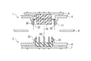
- FIG. 2 is a schematic exploded partial cross-sectional view before connector fitting for explaining the connector connection structure of the present invention.
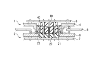
- FIG. 3 is a schematic partial cross-sectional view after connector fitting for explaining the connector connection structure of the present invention.
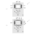
- FIG. 4 is a schematic plan view for explaining the vicinity of the first connector assembly of the connector connection structure of the present invention.
- FIG. 5 is a schematic partial cross-sectional view after connector fitting for explaining a state in which the connector fitting of the connector connection structure of the present invention is displaced.
- the connector connection structure of this invention is not limited to that used in the vehicular antenna device, and any connector connection structure may be used as long as it has a connector connection portion at the fitting portion between the first member and the second member. Also good.
- FIG. 1 is a schematic exploded perspective view for explaining an overall configuration when the connector connection structure of the present invention is applied to a vehicle antenna device.
- This vehicular antenna device is composed of a vehicle exterior antenna 1 as a first member and a vehicle interior antenna module 2 as a second member.
- the vehicle exterior antenna 1 and the vehicle interior antenna module 2 are fastened and fixed via a vehicle roof R.
- the vehicle roof R is sandwiched between the vehicle exterior antenna 1 and the vehicle interior antenna module 2, and is fastened and fixed by screws or the like at the fastening portion 9.
- the vehicle exterior antenna 1 is disposed on the vehicle roof R.
- the vehicle exterior antenna 1 includes, for example, an antenna base 4 and an antenna element 5. These are covered with an antenna cover 3.
- the antenna base 4 may be a conductive base or an insulating base, or may be a composite base of a conductor and an insulator.
- Various elements are mounted on the antenna element 5 so as to be compatible with various wireless communications such as terrestrial radio, satellite radio, GNSS, mobile phone, and DSRC for V2X communication.
- the vehicle interior antenna module 2 is fastened and fixed to the vehicle exterior antenna 1.
- the in-vehicle antenna module 2 is for processing signals from various external antennas 1 such as terrestrial radio, satellite radio, GNSS, mobile phone, and DSRC for V2X communication.
- the first connector assembly 10 of the connector connection structure of the present invention is provided in the vehicle exterior antenna 1 as the first member, and the second connector assembly 20 is the vehicle interior antenna module 2 as the second member. Is provided.
- the connector connection structure portion of the present invention will be described in detail.
- FIG. 2 is a schematic exploded partial cross-sectional view before connector fitting for explaining the connector connection structure of the present invention.
- FIG. 3 is a schematic partial cross-sectional view after connector fitting for explaining the connector connection structure of the present invention.
- the same reference numerals as those in FIG. 1 denote the same parts.
- the connector connection structure of the present invention includes a first connector assembly 10, a first protective wall 11, a second connector assembly 20, a second protective wall 21, a guide portion 30, and an elastic member 40. It consists of
- the first connector assembly 10 is provided on the vehicle exterior antenna 1 that is the first member. Specifically, the first connector assembly 10 may be provided on the surface side of the antenna base 4 of the vehicle exterior antenna 1 on the vehicle interior antenna module 2 side. The first connector assembly 10 is connected to a second connector assembly 20 described later to connect a signal line. The first connector assembly 10 may be configured with precise fitting accuracy so as to be compatible with, for example, a high frequency band.
- the first connector assembly 10 used in the connector connection structure of the present invention has six coaxial terminals, for example. In the connector connection structure of the present invention, the number of terminals of the first connector assembly 10 is not particularly limited to the illustrated example, and it is sufficient if there is at least one terminal. In the illustrated example, the first connector assembly 10 is a female connector.
- the first connector assembly 10 may be fixed to the antenna base 4 of the vehicle exterior antenna 1 or the vehicle exterior antenna side substrate 6 by soldering, screws, or the like.
- the first protective wall 11 is provided on the vehicle exterior antenna 1 which is the first member. Specifically, it may be provided on the surface side of the antenna base 4 of the vehicle exterior antenna 1 on the vehicle interior antenna module 2 side.
- the first protective wall 11 covers the periphery of the first connector assembly 10. In the illustrated example, the first protective wall 11 is configured to cover the periphery of the distal end side of the first connector assembly 10.
- the second connector assembly 20 is provided in the vehicle interior antenna module 2 which is the second member. Specifically, it may be provided on the surface side of the vehicle interior antenna module 2 on the vehicle exterior antenna 1 side.
- the second connector assembly 20 is to be fitted to the first connector assembly 10.
- the second connector assembly 20 has a plurality of terminals facing from the vehicle interior toward the vehicle exterior antenna 1.
- the second connector assembly 20 is placed on the in-vehicle antenna module side substrate 7 so that the terminals facing from the inside of the vehicle toward the outside antenna 1 are vertical.
- the second connector assembly 20 used in the connector connection structure of the present invention has six coaxial terminals, for example.
- the number of terminals of the second connector assembly 20 is not particularly limited to the illustrated example, and it is sufficient if there is at least one terminal.
- the second connector assembly 20 is a male connector.
- the second connector assembly 20 may be fixed to the in-vehicle antenna module side substrate 7 by soldering or screws.
- the second protective wall 21 is provided in the vehicle interior antenna module 2 which is the second member. Specifically, it may be provided on the surface side of the housing 8 of the vehicle interior antenna module 2 on the vehicle exterior antenna 1 side.
- the second protective wall 21 covers the periphery of the second connector assembly 20.
- the second protective wall 21 is configured to cover the periphery of the base side of the second connector assembly 20.
- the second protective wall 21 is configured to be covered with the first protective wall 11. That is, after the connector is fitted, the second connector assembly 20 is covered with the second protective wall 21 and the second protective wall 21 is covered with the first protective wall 11. ing.
- the periphery of the second protective wall 21 does not need to be entirely covered by the first protective wall 11, and the height may be adjusted so that a desired insertion amount is obtained.
- the outer surface of the 2nd protective wall 21 has the longitudinal cross-section taper shape 22 toward the vehicle exterior antenna 1 side. That is, the outer surface of the second protective wall 21 located on the inner surface side of the first protective wall 11 has a tapered shape having a predetermined taper angle.
- the first connector assembly 10 is separate from the first protective wall 11.
- the second connector assembly 20 is separate from the second protective wall 21.
- the antenna base 4 provided with the first protective wall 11 and the housing 8 provided with the second protective wall 21 are fastened and fixed. As shown in FIG. 2, since a tolerance is provided, a gap is provided between the first connector assembly 10 and the first protective wall 11 or between the second connector assembly 20 and the second protective wall 21. It has been.
- the connector connection structure of this invention has the guide part 30.
- FIG. The guide part 30 is provided on the first protective wall 11. And the guide part 30 is provided so that a slide is possible so that the clearance gap between the 1st protective wall 11 and the 2nd protective wall 21 may be filled. That is, the guide part 30 is disposed on the inner surface side of the first protective wall 11 and is provided so as to be sandwiched in a gap between the first protective wall 11 and the second protective wall 21 formed after the connector is fitted. As illustrated, the guide portion 30 may be provided so as to be slidable in the fitting direction between the first connector assembly 10 and the second connector assembly 20.
- the guide portion 30 has a longitudinal section taper shape 32 toward the vehicle interior antenna module 2 so that the surface of the guide section 30 on the second protection wall 21 side is in surface contact with the longitudinal section taper shape 22 of the second protection wall 21. Yes. That is, the tapered surface 32 of the guide portion 30 and the tapered surface 22 of the second protective wall 21 are configured to be in surface contact.
- the thus configured guide portion 30 is pressed toward the vehicle interior antenna module 2 by the elastic member 40.
- the elastic member 40 is composed of a wire processing spring.
- the guide portion 30 protrudes most to the in-vehicle antenna module 2 side before the connector is fitted.
- the guide portion 30 slides up and down according to the size of the gap between the first protective wall 11 and the second protective wall 21, and comes into surface contact with the tapered surface 22 of the second protective wall 21. In this state, the guide portion 30 remains at a position where the gap is filled.
- the gap between the first protective wall 11 and the second protective wall 21 is filled with the guide portion 30 after the connector is fitted. Therefore, the first protective wall 11 and the second protective wall 21 are fitted with no gap, and there is no backlash. For this reason, when the vehicle interior antenna module 2 is fastened and fixed to the vehicle exterior antenna 1 via the vehicle roof R, even if the vehicle exterior antenna 1 and the vehicle interior antenna module 2 are rotated together, a relative rotational deviation may occur. Absent. That is, the positional relationship between the first protective wall 11 and the second protective wall 21 is rotated with the guide portion 30 being fixed. Therefore, relative displacement cannot occur in the connector fitting portions of the first connector assembly 10 and the second connector assembly 20 surrounded by the first protective wall 11 and the second protective wall 21, and the solder joint portion of the connector It is also possible to prevent cracks and poor contact at the terminals.
- the longitudinal cross-section taper shape 22 of the second protective wall 21 and the longitudinal cross-section taper shape 32 of the guide portion 30 only need to have a taper angle equal to or less than the friction angle.
- the taper angle By setting the taper angle to be equal to or smaller than the friction angle, the guide portion 30 pressed by the elastic member 40 is not pushed back even if a rotational force is applied when the vehicle exterior antenna 1 and the vehicle interior antenna module 2 are rotated together. Therefore, the guide portion 30 is reliably held in the gap between the first protective wall 11 and the second protective wall 21.
- the taper angle is not limited to the friction angle or less. However, if the pressing force is too strong, the guide portion 30 becomes difficult to slide or the vehicle exterior antenna 1 and the vehicle interior antenna module 2 are fastened. Since it may be an obstacle, it is preferable that the taper angle be equal to or less than the friction angle.
- the guide part 30 should just consist of a material which can endure the rotational force at the time of the outside antenna 1 and the in-vehicle antenna module 2 rotating by fastening. Specifically, a conductive member, ABS resin, or the like may be used.
- the guide part 30 of the connector connection structure of this invention is pinched
- FIG. 4 is a schematic plan view for explaining the vicinity of the first connector assembly of the connector connection structure of the present invention.
- FIG. 4 (a) is a view seen from the upper side of the vehicle exterior antenna 1, and FIG. ) Is a view from the underside of the vehicle exterior antenna 1.
- the same reference numerals as those in FIG. 2 denote the same parts.
- the guide portion 30 has a transverse cross section taper shape 34. That is, it has a tapered shape in the direction in which the first connector assembly 10 is arranged.
- the first protective wall 11 has a guide guide groove 12.
- the guide guide groove 12 has a cross section taper shape 14 according to the cross section taper shape 34 of the guide portion 30. That is, the guide portion 30 is formed to fit in the guide guide groove 12.
- the guide portion 30 is fitted so as to be movable in the fitting direction between the first connector assembly 10 and the second connector assembly 20. With such a configuration, it is possible to prevent the guide portion 30 from falling to the first connector assembly 10 side.
- a pair of guide portions 30 are provided at positions where a gap between the first protective wall 11 and the second protective wall 21 is opposed.
- the first connector assembly 10 is configured in a rectangular shape, and a pair of guide portions 30 are provided at opposing positions on the short side.
- the guide portions 30 may be provided on all sides so as to surround the first connector assembly 10.
- the guide is provided so as to fill the gap between the first protective wall 11 and the second protective wall 21. Department is provided.
- the guide part 30 should just be provided so that the clearance gap of the direction which can be rotated at least among the clearance gaps between the 1st protection wall 11 and the 2nd protection wall 21 is filled.
- the arrangement position of the guide portion 30 is determined by the positional relationship between the connector fitting portions of the first connector assembly 10 and the second connector assembly 20 and the fastening portions 9 of the vehicle exterior antenna 1 and the vehicle interior antenna module 2. Just decide.
- the fastening portion 9 is arranged below the first connector assembly 10 in the drawing, so that the accompanying rotation by fastening is in the left-right direction in the drawing. Therefore, the guide part 30 which fills the clearance gap between the 1st protective wall 11 and the 2nd protective wall 21 should just be provided in the left-right side which is the direction which can be accompanied.
- the elastic member 40 is shown to be provided around the first protective wall 11 in a ring shape.
- the elastic member 40 is a wire processing spring having a fixed portion 41 and a spring portion 42.
- the wire processing spring is formed by bending one linear elastic body into a predetermined shape.
- the fixing part 41 may be anything fixed to the spring fixing anchor 13 provided on the first protective wall 11.
- the spring fixing anchor 13 is disposed at the position of the first first protective wall 11 between the pair of guide portions 30.
- the spring part 42 is arrange
- the guide portion 30 is provided with a spring fixing claw 31, and the spring portion 42 is fixed to the spring fixing claw 31 so that the guide portion 30 can be pressed with a predetermined pressing force.
- the pair of guide portions 30 can be pressed in conjunction with each other. That is, it can be configured such that when one guide part 30 is lifted, a pressing force is generated so that the other guide part 30 is lowered.
- a pair of spring fixing anchors 13 are arranged on the longitudinal sides of the first protective wall 11, the elastic member 40 is processed into a ring shape, and a pair of fixing portions 41 is formed.
- the spring portions 42 are configured to be arranged on the left and right respectively.
- the present invention is not limited to this, and the spring fixing anchor 13 may be provided only on one side instead of the ring shape, and the spring portion 42 may be arranged on the left and right with the spring fixing anchor 13 as the center.
- the guide part 30 is configured to move differently on the left and right, the following effects can be obtained.
- the fitting position between the first connector assembly 10 and the second connector assembly 20 and the first protection The arrangement positions of the wall 11 and the second protective wall 21 may be relatively shifted.
- Such misalignment can be absorbed by the connector connection structure of the present invention.
- the connectors fit within a range in which the second protective wall 21 can be accommodated inside the first protective wall 11 due to tolerance. Will do.
- the gap between the first protective wall 11 and the second protective wall 21 can be asymmetric due to the displacement.
- the guide portion 30 of the connector connection structure of the present invention can cope with such an asymmetric gap.
- FIG. 5 is a schematic partial cross-sectional view after connector fitting for explaining a state in which the connector fitting of the connector connection structure of the present invention is displaced.
- the same reference numerals as those in FIG. 2 denote the same parts.
- the second connector assembly 20 is installed on the left side in the drawing with respect to the in-vehicle antenna module side substrate 7.
- the second protective wall 21 is shifted to the right in the drawing with respect to the first protective wall 11.
- the left side of the gap between the first protective wall 11 and the second protective wall 21 is wider.
- the right guide portion 30 is pushed upward as compared with the left guide portion 30.
- the right guide portion 30 is in surface contact with the narrow tip end side of the tapered shape 22 of the longitudinal section of the second protective wall 21, while the left guide portion 30 has a larger gap.
- Surface contact is made with the thick base side of the tapered shape 22. In this way, the height of the guide portion 30 is appropriately adjusted according to the gap even with respect to the asymmetric gap, and the gap between the first protective wall 11 and the second protective wall 21 is reliably filled.
- connector connection structure of the present invention is not limited to the illustrated example described above, and it is needless to say that various modifications can be made without departing from the gist of the present invention.
Landscapes
- Engineering & Computer Science (AREA)
- Mechanical Engineering (AREA)
- Details Of Connecting Devices For Male And Female Coupling (AREA)
- Coupling Device And Connection With Printed Circuit (AREA)
- Support Of Aerials (AREA)
- Fittings On The Vehicle Exterior For Carrying Loads, And Devices For Holding Or Mounting Articles (AREA)
Abstract
L'invention concerne une structure de connexion de connecteur pouvant absorber des variations et tolérances de fabrication. Cette structure de connexion de connecteur comprend un premier corps assemblé de connecteur 10, une première paroi de protection 11, un second corps assemblé de connecteur 20, une seconde paroi de protection 21, une partie de guidage 30 et un élément élastique 40. La première paroi de protection 11 couvre la périphérie du premier corps assemblé de connecteur 10. Le second corps assemblé de connecteur 20 s'accouple avec le premier corps assemblé de connecteur 10. La seconde paroi de protection 21 couvre la périphérie du second corps assemblé de connecteur 20 tout en étant recouverte par la première paroi de protection 11. Dans la seconde paroi de protection 21, la surface côté extérieur présente une forme de section verticale effilée 22. La partie de guidage 30 est disposée de façon à pouvoir glisser entre la première paroi de protection 11 et la seconde paroi de protection 21 afin de remplir l'espace entre elles. La surface de la partie de guidage 30 côté seconde paroi de protection 21 présente une forme de section verticale effilée 32 qui entre en contact avec la surface de la forme de section verticale effilée 22 de la seconde paroi de protection 21. L'élément élastique 40 pousse la partie de guidage 30 vers le bas.
Applications Claiming Priority (2)
| Application Number | Priority Date | Filing Date | Title |
|---|---|---|---|
| JP2018059020A JP2019175556A (ja) | 2018-03-26 | 2018-03-26 | コネクタ接続構造 |
| JP2018-059020 | 2018-03-26 |
Publications (1)
| Publication Number | Publication Date |
|---|---|
| WO2019188041A1 true WO2019188041A1 (fr) | 2019-10-03 |
Family
ID=68061428
Family Applications (1)
| Application Number | Title | Priority Date | Filing Date |
|---|---|---|---|
| PCT/JP2019/008582 Ceased WO2019188041A1 (fr) | 2018-03-26 | 2019-03-05 | Structure de connexion de connecteur |
Country Status (2)
| Country | Link |
|---|---|
| JP (1) | JP2019175556A (fr) |
| WO (1) | WO2019188041A1 (fr) |
Cited By (1)
| Publication number | Priority date | Publication date | Assignee | Title |
|---|---|---|---|---|
| WO2025026715A1 (fr) | 2023-08-02 | 2025-02-06 | Stellantis Auto Sas | Utilisation universelle d'une fente pour antenne dans un toit de véhicule |
Families Citing this family (1)
| Publication number | Priority date | Publication date | Assignee | Title |
|---|---|---|---|---|
| CN113783006B (zh) * | 2020-06-09 | 2022-11-11 | 华为技术有限公司 | 一种具有多单板对接的计算机设备和机框 |
Citations (6)
| Publication number | Priority date | Publication date | Assignee | Title |
|---|---|---|---|---|
| JP2005005096A (ja) * | 2003-06-11 | 2005-01-06 | Hirose Electric Co Ltd | 電気コネクタ |
| JP2005085575A (ja) * | 2003-09-08 | 2005-03-31 | Smk Corp | フローティング構造を有するコネクタ |
| KR20100041255A (ko) * | 2008-10-13 | 2010-04-22 | 현대자동차주식회사 | 차량용 수신기 일체형 통합 안테나 |
| WO2017001197A1 (fr) * | 2015-06-30 | 2017-01-05 | Continental Teves Ag & Co. Ohg | Mise en contact |
| JP2018014633A (ja) * | 2016-07-21 | 2018-01-25 | 住友電気工業株式会社 | 車載無線装置 |
| WO2019049739A1 (fr) * | 2017-09-07 | 2019-03-14 | 原田工業株式会社 | Dispositif d'antenne pour véhicule |
-
2018
- 2018-03-26 JP JP2018059020A patent/JP2019175556A/ja not_active Ceased
-
2019
- 2019-03-05 WO PCT/JP2019/008582 patent/WO2019188041A1/fr not_active Ceased
Patent Citations (6)
| Publication number | Priority date | Publication date | Assignee | Title |
|---|---|---|---|---|
| JP2005005096A (ja) * | 2003-06-11 | 2005-01-06 | Hirose Electric Co Ltd | 電気コネクタ |
| JP2005085575A (ja) * | 2003-09-08 | 2005-03-31 | Smk Corp | フローティング構造を有するコネクタ |
| KR20100041255A (ko) * | 2008-10-13 | 2010-04-22 | 현대자동차주식회사 | 차량용 수신기 일체형 통합 안테나 |
| WO2017001197A1 (fr) * | 2015-06-30 | 2017-01-05 | Continental Teves Ag & Co. Ohg | Mise en contact |
| JP2018014633A (ja) * | 2016-07-21 | 2018-01-25 | 住友電気工業株式会社 | 車載無線装置 |
| WO2019049739A1 (fr) * | 2017-09-07 | 2019-03-14 | 原田工業株式会社 | Dispositif d'antenne pour véhicule |
Cited By (2)
| Publication number | Priority date | Publication date | Assignee | Title |
|---|---|---|---|---|
| WO2025026715A1 (fr) | 2023-08-02 | 2025-02-06 | Stellantis Auto Sas | Utilisation universelle d'une fente pour antenne dans un toit de véhicule |
| DE102023207412A1 (de) | 2023-08-02 | 2025-02-06 | Fca Us Llc | Universelle Nutzung des Antennenausschnitts im Fahrzeugdach |
Also Published As
| Publication number | Publication date |
|---|---|
| JP2019175556A (ja) | 2019-10-10 |
Similar Documents
| Publication | Publication Date | Title |
|---|---|---|
| US10741903B1 (en) | Vehicle antenna device | |
| JP7187975B2 (ja) | 同軸コネクタ装置 | |
| KR101343814B1 (ko) | 안테나 모듈과 튜너부 모듈이 일체화된 차량용 멀티미디어 장치 | |
| JP5757153B2 (ja) | 同軸コネクタ装置 | |
| US11631954B2 (en) | Coaxial connector for a circuit board | |
| US20190044258A1 (en) | Cable connector block assemblies for base station antennas | |
| EP2581989A2 (fr) | Connecteur électrique coaxial | |
| JP4865848B2 (ja) | アンテナ設置方法及びこれに用いる同軸コネクタ | |
| US7909612B2 (en) | RF connector mounting means | |
| US20100159718A1 (en) | Coaxial Connector | |
| EP3793026B1 (fr) | Assemblage et système d'antenne rf | |
| WO2019188041A1 (fr) | Structure de connexion de connecteur | |
| CN103887626B (zh) | 同轴连接器 | |
| JP2008251214A (ja) | 接続端子構造 | |
| JP2005332644A (ja) | 接点装置 | |
| US20230411884A1 (en) | An improved connector for a low intermodulation board-to-board or board to filter rf coaxial connection assembly, integrating an elastic ball joint link | |
| JP2008535152A (ja) | 挿入接続コネクタ | |
| EP1978591A1 (fr) | Monopole ajustable avec plan de masse ajustable | |
| KR20210055528A (ko) | 캐비티 필터 | |
| KR102203367B1 (ko) | 커넥팅 장치 | |
| WO2024050728A1 (fr) | Ensemble de connexion pour une connexion multiple de module à carte (m2b) ou de module à module (m2m) comprenant une pluralité d'ensembles de connexion coaxiale unitaires dans lesquels le contact extérieur d'une prise fait partie intégrante du module de m2b ou de m2m | |
| JP2008205679A (ja) | 無線装置 | |
| CN219180797U (zh) | 用于多重的模块到板或模块到模块连接的连接组件 | |
| US12080978B2 (en) | High frequency impedance matching edge launch RF connector | |
| KR200340388Y1 (ko) | 보드실장이 용이한 에스엠에이 커넥터 |
Legal Events
| Date | Code | Title | Description |
|---|---|---|---|
| 121 | Ep: the epo has been informed by wipo that ep was designated in this application |
Ref document number: 19777887 Country of ref document: EP Kind code of ref document: A1 |
|
| NENP | Non-entry into the national phase |
Ref country code: DE |
|
| 122 | Ep: pct application non-entry in european phase |
Ref document number: 19777887 Country of ref document: EP Kind code of ref document: A1 |