WO2019188341A1 - 吸着パッド - Google Patents
吸着パッド Download PDFInfo
- Publication number
- WO2019188341A1 WO2019188341A1 PCT/JP2019/010533 JP2019010533W WO2019188341A1 WO 2019188341 A1 WO2019188341 A1 WO 2019188341A1 JP 2019010533 W JP2019010533 W JP 2019010533W WO 2019188341 A1 WO2019188341 A1 WO 2019188341A1
- Authority
- WO
- WIPO (PCT)
- Prior art keywords
- adsorbed
- adsorption
- electrode layer
- electrode
- resin film
- Prior art date
- Legal status (The legal status is an assumption and is not a legal conclusion. Google has not performed a legal analysis and makes no representation as to the accuracy of the status listed.)
- Ceased
Links
Images


Classifications
-
- A—HUMAN NECESSITIES
- A61—MEDICAL OR VETERINARY SCIENCE; HYGIENE
- A61B—DIAGNOSIS; SURGERY; IDENTIFICATION
- A61B5/00—Measuring for diagnostic purposes; Identification of persons
- A61B5/68—Arrangements of detecting, measuring or recording means, e.g. sensors, in relation to patient
- A61B5/6801—Arrangements of detecting, measuring or recording means, e.g. sensors, in relation to patient specially adapted to be attached to or worn on the body surface
- A61B5/683—Means for maintaining contact with the body
-
- A—HUMAN NECESSITIES
- A61—MEDICAL OR VETERINARY SCIENCE; HYGIENE
- A61B—DIAGNOSIS; SURGERY; IDENTIFICATION
- A61B5/00—Measuring for diagnostic purposes; Identification of persons
- A61B5/24—Detecting, measuring or recording bioelectric or biomagnetic signals of the body or parts thereof
- A61B5/25—Bioelectric electrodes therefor
- A61B5/251—Means for maintaining electrode contact with the body
- A61B5/252—Means for maintaining electrode contact with the body by suction
-
- A—HUMAN NECESSITIES
- A61—MEDICAL OR VETERINARY SCIENCE; HYGIENE
- A61B—DIAGNOSIS; SURGERY; IDENTIFICATION
- A61B5/00—Measuring for diagnostic purposes; Identification of persons
- A61B5/24—Detecting, measuring or recording bioelectric or biomagnetic signals of the body or parts thereof
- A61B5/25—Bioelectric electrodes therefor
- A61B5/263—Bioelectric electrodes therefor characterised by the electrode materials
-
- H—ELECTRICITY
- H02—GENERATION; CONVERSION OR DISTRIBUTION OF ELECTRIC POWER
- H02N—ELECTRIC MACHINES NOT OTHERWISE PROVIDED FOR
- H02N13/00—Clutches or holding devices using electrostatic attraction, e.g. using Johnson-Rahbek effect
-
- A—HUMAN NECESSITIES
- A61—MEDICAL OR VETERINARY SCIENCE; HYGIENE
- A61B—DIAGNOSIS; SURGERY; IDENTIFICATION
- A61B2562/00—Details of sensors; Constructional details of sensor housings or probes; Accessories for sensors
- A61B2562/02—Details of sensors specially adapted for in-vivo measurements
- A61B2562/0209—Special features of electrodes classified in A61B5/24, A61B5/25, A61B5/283, A61B5/291, A61B5/296, A61B5/053
-
- A—HUMAN NECESSITIES
- A61—MEDICAL OR VETERINARY SCIENCE; HYGIENE
- A61B—DIAGNOSIS; SURGERY; IDENTIFICATION
- A61B2562/00—Details of sensors; Constructional details of sensor housings or probes; Accessories for sensors
- A61B2562/14—Coupling media or elements to improve sensor contact with skin or tissue
Definitions
- the present invention relates to an adsorption pad that is used by adsorbing to an object to be adsorbed by using an electric adsorption force, and more specifically, not only a conductor but also, for example, an animal, a plant and a processed product thereof.
- the present invention relates to an object to be adsorbed that is soft and has a certain amount of moisture and oil, and more particularly to an adsorption pad that can be adsorbed and held on the skin of a human body.
- Electrostatic chucks are mainly used for industrial use for attracting and holding semiconductor substrates and glass substrates, and usually have a structure in which electrodes are sandwiched between dielectrics from above and below.
- a voltage to the electrode according to the principle there are those that can adsorb the object to be adsorbed with the surface of one of the dielectrics as the adsorbing surface, and depending on the case, it is equipped with heating means or a conduit for flowing refrigerant It has a structure in which it is integrally bonded to a metal base.
- the inventors of the present application have proposed an electrostatic chuck structure that applies the electrostatic chuck structure and principle. Yes.
- Patent Document 1 a plurality of sheet members each having two dielectrics sandwiched between electrodes can be stacked, and a voltage can be applied between the electrodes to adsorb and fix the members to each other. It is very convenient to change the structure so that sheet materials and objects to be adsorbed can be easily separated by removing the voltage after use.
- An electrostatic adsorption structure has been proposed.
- the surface of the electrostatic chuck having an adsorption electrode sandwiched between two insulating layers is used as an attaching / detaching means, and a film-like solar cell is attached to the surface so that the selectivity of the installation location can be improved.
- a power generator with good detachability has been proposed.
- the electrostatic adsorption structure power generation device
- a living body for example, the skin of a human body
- the detailed cause is Although it is not certain, it is speculated that the adsorption force will decrease due to reverse charging on the surface of the electrostatic chuck, and the occurrence of this reverse charging and the decrease in adsorption force are more noticeable than when using a semiconductor substrate. From this, it is inferred that the moisture and oil content of the human skin cause this more strongly.
- the conventional electrostatic chuck requires a sufficient contact area between the object and the chuck in order to obtain a sufficient attracting force.
- Both the suction target side and the chuck side were flat and uniform.
- a conventional electrostatic chuck can contact only a part of the attracting surface and has a sufficient attracting force. It was found that could not be obtained.
- the inventors of the present application adsorbed to an object to be adsorbed that is soft and has a certain amount of moisture and oil, especially human skin, using electric adsorption force.
- a resin film having a specific tensile elastic modulus and a specific volume resistance value is adopted at least on the adsorption surface for the object to be adsorbed, and this is used as an electrode layer together with other resin films.
- the laminated sheet is sandwiched between layers, and it has a simple suction pad configuration that is used with a power supply device that can apply voltage to the electrode layer.
- the present invention was completed by finding for the first time that it can be adsorbed and held with good followability, particularly on human skin.
- an object of the present invention is to provide a suction pad that can be attracted and held with good followability to human skin, in particular, by utilizing the electrical attraction force.
- the gist of the present invention is as follows.
- Adsorption pad used by adsorbing to an object to be adsorbed a first resin film having a thickness of 20 to 200 ⁇ m, an electrode layer having a thickness of 1 to 20 ⁇ m, and a second resin film having a thickness of 20 to 200 ⁇ m
- a power supply device for applying a voltage to the electrode layer At least the tensile modulus of the second resin film is 1 MPa or more and less than 100 MPa and the volume resistivity is 1 ⁇ .
- the suction pad according to [1] wherein the second resin film is made of soft polyvinyl chloride.
- the adsorbent is one selected from the group consisting of human skin, organs, animal skin, plants, meat and processed meat products, vegetables and processed vegetable products, and fruits and processed fruit products, or a combination thereof.
- the adsorption method is characterized in that a voltage is applied to the electrode layer to adsorb the adsorption pad and the adsorbent while the electric potential of the adsorbent is approximately 0V.
- An adsorption method for adsorbing the adsorption pad according to any one of [1] to [3] or [5] to an object to be adsorbed An electrode layer composed of a monopolar electrode is used as the electrode layer, and the potential of the object to be adsorbed becomes approximately 0 V by connecting the ground of the voltage generation source in the power supply apparatus and the object to be adsorbed to the earth. While doing so, a voltage is applied to the electrode layer to adsorb the adsorption pad and the object to be adsorbed.
- an adsorbent pad that can be adsorbed and held with good followability to an object to be adsorbed, particularly a human skin, that is soft and has a certain amount of moisture and oil while utilizing electric adsorption force.
- an object to be adsorbed particularly a human skin
- electric adsorption force can be provided. Since it can be adsorbed and fixed by electric adsorption force in this way, it can be used repeatedly without using chemical bonding means such as adhesives and adhesives, and it can be used for mold release. Since no film or the like is required, it is simple and cost-effective.
- wearable electrical products such as human skin and the like and the surface of an adsorbed object corresponding to the human skin (for example, various sensors that read biological information, medical devices, decorations, etc.)
- various sensors that read biological information, medical devices, decorations, etc.
- medical, beauty, sports, apparel, wearable devices, etc. are expected to expand into fields and industries.
- FIG. 1 is a schematic diagram for explaining one embodiment of a bipolar laminate sheet, (i) is a plan view, and (ii) is a sectional explanatory view explaining a state before lamination in the AA section. (Iii) is a cross-sectional explanatory diagram for explaining a state before lamination in the BB cross section. The white arrows in (ii) and (iii) indicate the adsorption surface for the object to be adsorbed.
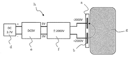
- FIG. 2 is a schematic explanatory diagram for explaining an embodiment (circuit configuration) in which the bipolar laminated sheet shown in FIG. 1 is used together with a power supply device to form a suction pad of the present invention.
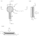
- FIG. 3 is a schematic view for explaining a monopolar laminated sheet used in the examples, (i) is a plan view, and (ii) is a state before lamination in the XX cross section.
- FIG. 6 is a cross-sectional explanatory diagram, and (iii) is a cross-sectional explanatory diagram illustrating a state before lamination in a YY cross section.
- the white arrows in (ii) and (iii) indicate the adsorption surface for the object to be adsorbed.
- FIG. 4 is a schematic explanatory view for explaining an embodiment (circuit configuration) used as the suction pad of the present invention together with the monopolar laminated sheet power supply device shown in FIG.
- FIG. 5 is an explanatory photograph for explaining a method of evaluating the adsorptivity of the suction pad performed in the example.
- a white arrow in the figure indicates a vertically downward direction.
- the suction pad of the present invention is a laminate in which at least a first resin film, an electrode layer, and a second resin film are sequentially laminated, and the electrode layer is sandwiched between the resin films.
- a sheet and a power supply device that applies a voltage to the electrode layer are provided.
- the electrode layer is a bipolar type having a positive electrode and a negative electrode, or, as shown in FIGS. 3 and 4, it has only a positive (negative) electrode and is negative.
- the (positive) electrode side may be a monopolar type that is grounded.
- the second resin film is used as an adsorption surface for an object to be adsorbed.
- the volume resistivity of the resin film needs to be 1 ⁇ 10 10 to 10 13 ⁇ ⁇ cm.
- the adsorption power to an object to be adsorbed decreases, For example, even the weight of the suction pad falls.
- the volume resistivity is less than 1 ⁇ 10 10 ⁇ ⁇ cm, it is estimated that the adsorption force itself acting on the object to be adsorbed increases, but a small discharge is continuously generated between the adsorbent pad and the object to be adsorbed. In particular, when used on the human body, it may be accompanied by itching and pain, which may cause damage to the skin, which is not preferable.
- the volume resistivity is 1 ⁇ 10 10 to 10 12 ⁇ ⁇ cm from both aspects of the attraction force and safety.
- the volume resistivity of the first resin film used on the side opposite to the adsorption surface of the object to be adsorbed can be appropriately set, but it flows between the object to be adsorbed through the second resin film. Since there is a possibility that a current should flow to the first resin film side, the volume resistivity of the first resin film is preferably the same as or larger than the volume resistivity of the second resin film.
- the tensile elastic modulus (Young's modulus) needs to be 1 MPa or more and less than 100 MPa.
- the detailed principle is not clear, but it is possible to adsorb following the shape of the object to be adsorbed and Since the resin film is required to hold the adsorbed state by suppressing the repulsive force (stress) generated inside the adsorbing pad as much as possible when adsorbing to the adsorbent pad, at least the adsorbing surface and The tensile elastic modulus (Young's modulus) of the second resin film is within the above range.
- the tensile elastic modulus (Young's modulus) of the first resin film is the same as or smaller than the tensile elastic modulus (Young's modulus) of the second resin film.
- each of the first and second resin films needs to have a thickness of 20 to 200 ⁇ m in order to ensure insulation, followability of adsorption to the object to be adsorbed, and adsorption force.
- the thickness is preferably 50 to 100 ⁇ m.
- the thickness is less than 20 ⁇ m, dielectric breakdown is likely to occur, and if a pinhole is formed in the resin film, there is a possibility that it does not function as a suction pad.
- it exceeds 200 ⁇ m the followability of the adsorption to the adsorbent is inferior, and the distance to the adsorbent becomes large.
- the first and second resin films may be the same or different, but polyimide, polyethylene terephthalate (PET), nylon, polypropylene, polyurethane , Soft polyvinyl chloride, polyvinylidene chloride and the like, or those processed (mixed with a filler, etc.) to adjust their conductivity.
- the second resin film is preferably polyurethane or soft polyvinyl chloride, more preferably soft polyvinyl chloride, so that the volume resistivity and tensile elastic modulus are within the predetermined ranges. is there.
- the material, shape and the like of the electrode layer used in the present invention are not particularly limited, but the thickness needs to be 1 to 20 ⁇ m. If the thickness is less than 1 ⁇ m, the electrode layer may be disconnected or the conductivity may be lowered due to deformation of the suction pad. On the other hand, if the thickness exceeds 20 ⁇ m, the hardness of the electrode layer tends to increase. For this reason, the flexibility of the entire adsorption pad is hindered, and the followability to the object to be adsorbed may be poor.
- a metal foil may be used as it is, or a metal film formed by sputtering, ion plating or the like may be obtained by etching into a predetermined shape, or a metal material may be sprayed. Alternatively, it may be formed into a predetermined shape by printing conductive ink.
- a flat plate shape, a semicircular shape, a comb shape, a pattern shape such as a mesh, or the like can be selected as appropriate.
- a power supply device for applying a voltage to the electrode layer to generate an electrical adsorption force is required.
- the power supply device can be connected to the electrode layer of the laminated sheet via a connection terminal and a switch (both not shown), and the same power supply device as that used in a general electrostatic adsorption structure should be used. It is sufficient if it can generate a DC high voltage.
- the potential difference to be generated can be about 500 to 5000 V, and a booster circuit (high voltage generation circuit) capable of boosting to a required voltage may be provided as necessary.
- the suction pad of the present invention in order to apply the suction pad of the present invention to the skin of a human body, it is preferable to design in consideration of the following (a) to (c). That is, (A) Apply as high a voltage as possible in order to generate sufficient adsorption power. (B) Make the potential of the human body as low as possible. This is because if the electric potential applied to the human body is biased to either positive or negative, static electricity is accumulated in the human body and receives an impact during discharge. (C) In the unlikely event that a current that may cause danger to the human body does not flow.
- the output current from the power source it is preferable to suppress the output current from the power source to 0.5 mA or less. This is because the human body usually cannot be perceived if it is 0.5 mA or less. However, if the current is stored in the suction pad or the human body and discharged at once, a large current may be generated, so the capacitance of the suction pad is 1000 pF or less, which is the same as the human body, specifically By setting the voltage to about 10 pF to 100 pF and the voltage within ⁇ 5000 V, even if it is stored in the human body, it will be 5 ⁇ C or less, so it is preferable to set in this way.
- the suction pad of the present invention is provided with the laminated sheet and the power supply device as described above.
- the suction pad of the present invention may be separately provided with a sensor or the like as necessary.
- the configuration of the suction layer may be changed or added as appropriate within the scope of the object of the present invention, such as a change in the pattern of the electrode layer. It may be broken.
- an adsorbed object not only a conductor but also paper or cloth having poor electrical conductivity can be targeted, and in particular, soft skin corresponding to human body skin including human skin.
- a thing which has a certain amount of moisture and oil and has a certain surface that can be contacted and adsorbed by the suction pad for example, organ, animal skin, plant, meat and processed meat, vegetable and processed vegetable
- -Foods such as fruits and processed fruits, or combinations thereof
- the produced laminated sheet a is composed of, for example, a power supply device [battery d (DC 3.7 V), DCDC converter e (5 V output) and high voltage generation circuit f ( ⁇ 2000 V output) as shown in FIG.
- a suction pad h according to the present invention and applying positive (+2000 V) and negative ( ⁇ 2000 V) symmetrical voltages to the first electrode and the second electrode in the electrode layer, respectively. It can be attached to the adsorbent (human body skin) g so that the potential of the adsorbent (human body) is approximately 0V.
- Example 1 ⁇ Preparation of suction pad> As a monopolar suction pad, an aluminum foil b (thickness: 0.012 mm) having a predetermined shape having dimensions (unit: mm) as shown in FIG. 3 is used as an electrode layer.
- a soft polyvinyl chloride film c ′ [volume resistivity: 1 ⁇ 10 10 ⁇ ⁇ cm (measured by a method described later), tensile elastic modulus (Young's modulus): 20 to 30 MPa
- polyimide film c (trade name: Kapton (registered trademark) H, thickness 25 ⁇ m, manufactured by Toray DuPont Co., Ltd.) is used as the first resin film used on the surface opposite to the adsorption surface.
- an adhesive layer (not shown) made of silicone with a thickness of 30 ⁇ m separately for the first resin film, all of these are pressure-bonded and bonded together, and the electrode layer is attached to the first and second resin films.
- a power supply device [commercial power supply d ′ (AC 100 V), AC adapter e ′ (5 V output) and high voltage generating circuit f ( ⁇ 4000 V output) as shown in FIG.
- a suction pad h ′ according to the present invention which was attached to an object to be adsorbed (human skin) g.
- the object to be adsorbed (human skin) g and the ground (not shown) of the high voltage generation circuit f were grounded.
- the volume resistivity of the soft polyvinyl chloride film in Example 1 was measured by the double ring electrode method (IEC60093, ASTM D257, JIS K6911, JIS K6271), and Examples 2 to 6 and Comparative Examples described later were used.
- the volume resistivity of each resin film used in 1 to 3 was also measured by the same method.
- the second resin film c ′ serving as the adsorption surface of the object to be adsorbed has a volume resistivity of 1 ⁇ 10 12 ⁇ ⁇ cm (measured by the method described above) and a tensile modulus (Young's modulus) of 20 to 30 MPa.
- a suction pad according to Example 2 was prepared in the same manner as in Example 1 except that a certain soft polyvinyl chloride film (thickness: 100 ⁇ m) was used, and the adsorptivity was similarly evaluated. The results are as shown in Table 1.
- Example 3 A soft polyvinyl chloride film (thickness: 100 ⁇ m) having a volume resistivity of 1 ⁇ 10 13 ⁇ ⁇ cm (measured by the method described above) was used as the second resin film c ′ serving as the adsorption surface of the object to be adsorbed. Except for the above, the suction pad according to Example 3 was produced in the same manner as in Example 1, and the adsorptivity was similarly evaluated. The results are as shown in Table 1.
- Example 4 The adsorption pad h ′ used in Example 1 was used, and the adsorbate g ′ was adsorbed on the surface thereof using a foliage plant leaf (plant name: Ficus umbellata) instead of the human skin. Except for the above, the adsorptivity was evaluated in the same manner as in Example 1. The results are as shown in Table 1.
- Example 5 Using the suction pad h ′ used in Example 1 above, and using the processed pork meat (trade name: Loinham, manufactured by Foodelier Co., Ltd.) instead of the human skin as the adsorbent g ′, the oil content on the surface is somewhat The adsorptivity was evaluated in the same manner as in Example 1 except that the surface was adsorbed after wiping. The results are as shown in Table 1.
- Example 3 Using the suction pad h ′ used in Example 1, and using the vegetable eggplant instead of the human skin as the object to be adsorbed g ′, it is adsorbed from the surface of the skin without cutting or other processing.
- the adsorptivity was evaluated in the same manner as in Example 1 except for the above. The results are as shown in Table 1.
- PET film [trade name: Lumirror (registered trademark) S10, manufactured by Toray Industries, Inc., volume resistivity: 1 ⁇ 10 17 ⁇ ⁇ cm as the second resin film c ′ serving as the adsorption surface of the object to be adsorbed (Measured by the method described above), tensile elastic modulus (Young's modulus): 4 ⁇ 10 3 MPa, thickness 50 ⁇ m] was used in the same manner as in Example 1 except that the suction pad h ′ according to Comparative Example 3 was used. In addition, the adsorptivity of human skin was evaluated in the same manner. The results are as shown in Table 1.
- a ... laminated sheet (bipolar type), a '... laminated sheet (monopolar type), b ... electrode layer, c ... first resin film, c' ... second resin film, d ... battery, d '... commercial Power supply, e ... DCDC converter, e '... AC adapter, f ... high voltage generation circuit, g ⁇ g' ... adsorbed object (human body skin, etc.), h ... adsorption pad (bipolar type), h '... adsorption pad (single Polar), i ... ground, j ... weight.
Landscapes
- Health & Medical Sciences (AREA)
- Life Sciences & Earth Sciences (AREA)
- Medical Informatics (AREA)
- Biophysics (AREA)
- Pathology (AREA)
- Engineering & Computer Science (AREA)
- Biomedical Technology (AREA)
- Heart & Thoracic Surgery (AREA)
- Physics & Mathematics (AREA)
- Molecular Biology (AREA)
- Surgery (AREA)
- Animal Behavior & Ethology (AREA)
- General Health & Medical Sciences (AREA)
- Public Health (AREA)
- Veterinary Medicine (AREA)
- Laminated Bodies (AREA)
- Measurement And Recording Of Electrical Phenomena And Electrical Characteristics Of The Living Body (AREA)
- Cardiology (AREA)
- Electrotherapy Devices (AREA)
Abstract
Description
[1]被吸着物に吸着させて用いる吸着パッドであって、厚さ20~200μmの第1の樹脂フィルム、厚さ1~20μmの電極層、及び厚さ20~200μmの第2の樹脂フィルムが順次積層された積層シートと、前記電極層に電圧を印加する電源装置とを備えて、少なくとも前記第2の樹脂フィルムの引張弾性率が1MPa以上100MPa未満であると共にその体積抵抗率が1×10¹⁰~1013Ω・cmであり、前記電極層に電圧が印加されて発生する電気的吸着力により、前記第2の樹脂フィルムを吸着面として、被吸着物に吸着させることができることを特徴とする吸着パッド。
[2]前記第2の樹脂フィルムが、軟質ポリ塩化ビニルからなる[1]に記載の吸着パッド。
[3]被吸着物が、人体皮膚、臓器、動物の皮膚、植物、肉及び肉加工物、野菜及び野菜加工物、並びに果物及び果物加工物からなる群から選択されるいずれか又はその組み合わせである[1]又は[2]に記載の吸着パッド。
[4]前記電極層が、第1の電極及び第2の電極を有した双極型電極からなる[1]~[3]のいずれかに記載の吸着パッド。
[5]前記電極層が、単極型電極からなる[1]~[3]のいずれかに記載の吸着パッド。
[6]前記[1]~[4]のいずれかに記載の吸着パッドを被吸着物に吸着する吸着方法であって、
電極層として、第1の電極及び第2の電極を有した双極型電極からなる電極層を使用し、前記第1の電極及び第2の電極のそれぞれに、プラス又はマイナスの対称な電圧をかけることにより、被吸着物の電位が略0Vとなるようにしながら、前記電極層に電圧を印加して、吸着パッドと被吸着物とを吸着させることを特徴とする吸着方法。
[7]前記[1]~[3]又は[5]のいずれかに記載の吸着パッドを被吸着物に吸着する吸着方法であって、
電極層として単極型電極からなる電極層を使用し、前記電源装置における電圧の発生源のグラウンドと、被吸着物とをアース接続(接地)することにより被吸着物の電位が略0Vとなるようにしながら、前記電極層に電圧を印加して、吸着パッドと被吸着物とを吸着させることを特徴とする吸着方法。
本発明の吸着パッドは、図1~4に示されるように、少なくとも、第1の樹脂フィルム、電極層及び第2の樹脂フィルムが順次積層されて、電極層が樹脂フィルムに挟み込まれてなる積層シートと、電極層に電圧を印加する電源装置とを備える。また、図1及び2に示されるように、電極層として、正電極及び負電極を有する双極型か、或いは、図3及び4に示されるように、正(負)電極のみを有して負(正)電極側は接地される単極型であってよい。以下、各構成について詳しく説明する。
本発明の吸着パッドで使用される第1及び第2の樹脂フィルムについて、本発明においては、第2の樹脂フィルムを被吸着物に対する吸着面とするが、少なくともこの吸着面となる当該第2の樹脂フィルムの体積抵抗率が1×10¹⁰~1013Ω・cmであることが必要である。後述の実施例で示される通り、この吸着面の第2の樹脂フィルムの体積抵抗率が1×10¹³Ω・cmを超えると、被吸着物(人体皮膚等)に対する吸着力が低下して、例えば、吸着パッドの自重でも落下するようになる。一方で、体積抵抗率が1×10¹⁰Ω・cm未満であると、被吸着物に作用する吸着力自体は大きくなると推測されるものの、吸着パットと被吸着物の間で小さな放電が連続的に発生し、特に人体に用いる上では痒みや痛みを伴う場合もあり、皮膚にダメージを与える可能性があることから、好ましくない。好ましくは、吸着力の発現と安全性との両面から、当該体積抵抗率が1×10¹⁰~1012Ω・cmであることがよい。
なお、本発明において被吸着物の吸着面とは反対側に使用する第1の樹脂フィルムについては、その体積抵抗率を適宜設定できるが、第2の樹脂フィルムを通じて被吸着物との間に流れるべき電流を第1の樹脂フィルム側へ流してしまう虞があることから、第1の樹脂フィルムの体積抵抗率は第2の樹脂フィルムの体積抵抗率と同じか、それよりも大きいことが好ましい。
本発明において使用される電極層は、その材質、形状などについては特に限定されないが、その厚みを1~20μmとする必要がある。厚みが1μm未満の場合には、吸着パッドの変形により電極層の断絶や導電性の低下が起こる虞があり、一方で、厚みが20μmを超える場合には、電極層の硬度が高くなる傾向があることから吸着パット全体の柔軟性が阻害され、被吸着物に対する追従性に乏しくなる虞がある。材質、製法については、例えば、金属箔をそのまま用いたり、スパッタ法、イオンプレーティング法などにより成膜した金属を所定の形状にエッチングして得たりしたものでもよく、また、金属材料を溶射したり、導電性インクを印刷したりして所定の形状としたものでもよい。形状としては、例えば、平板状、半円状、櫛歯状やメッシュのようなパターン形状など、適宜選定することができる。
そして、このような第1及び第2の樹脂フィルム並びに電極層を使用して、これらを積層して積層シートとする。電極層が露出しないように樹脂フィルムに挟み込む必要があり、具体的な方法としては、これらの樹脂フィルム及び電極層を順次積層させて、熱と圧力を加えて、樹脂フィルム自体の熱可塑性を利用して、融着させる方法がある。もしくは、必要に応じてボンディングシートや接着剤もしくは粘着剤を用いて接着させてもよい。ただし、吸着パッドを変形及び伸縮させたとき、接着層に別の素材が挿入されていると、変形及び伸縮を阻害したり、接着面の剥離が起こったりする虞があるため、フィルムの熱可塑性によって融着させる方法が好ましい。
前記のように積層シートを形成した後には、電極層に電圧を印加して電気的吸着力を発生させるための電源装置が必要となる。電源装置は前記積層シートの電極層と接続端子およびスイッチ(いずれも図示外)を介して接続させることができて、一般的な静電吸着構造体で使用されるものと同様なものを用いることができ、直流の高電圧を発生できるものであればよい。発生させる電位差は500~5000V程度までとすることができ、必要に応じて、必要な電圧まで昇圧させることができる昇圧回路(高電圧発生回路)を備えるようにしてもよい。特に、本発明の吸着パッドを人体の皮膚に適用するためには、以下の(a)~(c)を考慮した設計とすることが好ましい。すなわち、
(a)十分な吸着力を生じさせるために、できるだけ高電圧を付与すること。
(b)人体の電位をできるだけ0Vにすること。人体に掛かる電位がプラス又はマイナスのどちらか一方に偏ると、人体内に静電気が溜まるようになり、放電時に衝撃を受けるからである。
(c)万が一でも、人体に危険を及ぶす程度の電流が流れないようにすること。
双極型の吸着パッドとして、図1に示すような寸法(単位:mm)を有する所定の形状の2枚のアルミ箔b(厚み:0.012mm)を電極層として、これを上下から2枚の軟質ポリ塩化ビニルからなる樹脂フィルムc及びc’〔いずれも、体積抵抗率:1×10¹⁰Ω・cm(後述の方法にて測定)、引張弾性率(ヤング率):20~30MPa、厚み100μm〕で挟み込んで、温度150℃で熱圧着して、双極型の積層シートaとした。
なお、この作製した積層シートaについては、例えば、図2に示すような電源装置〔電池d(DC3.7V)、DCDCコンバータe(5V出力)及び高電圧発生回路f(±2000V出力)からなる電源装置〕を備えて本発明に係る吸着パッドhとし、電極層における第1の電極及び第2の電極のそれぞれにプラス(+2000V)及びマイナス(-2000V)の対称な電圧をかけることにより、被吸着物(人体皮膚)gに対して、被吸着物(人体)の電位が略0Vとなるように取り付けることができる。
<吸着パッドの作製>
単極型の吸着パッドとして、図3に示すような寸法(単位:mm)を有する所定の形状を有する1枚のアルミ箔b(厚み:0.012mm)を電極層とし、また、被吸着物の吸着面となる第2の樹脂フィルムとして軟質ポリ塩化ビニルフィルムc’〔体積抵抗率:1×10¹⁰Ω・cm(後述の方法にて測定)、引張弾性率(ヤング率):20~30MPa、厚み100μm〕を用い、さらに、吸着面とは反対側の面に使用される第1の樹脂フィルムとしてポリイミドフィルムc〔東レ・デュポン株式会社製、商品名:カプトン(登録商標)H、厚み25μm〕を用い、前記第1の樹脂フィルムには別途厚み30μmのシリコーンからなる粘着層(図示外)を用いて、これら全てを圧着して貼り合わせて、電極層を第1及び第2の樹脂フィルムに挟み込んでなる単極型の積層シートa’として得た。
図5に示すように、人体(成人男性)の前腕部の皮膚g’に対して、前記で作製した実施例1の吸着パッドh’を、電源装置をONした上で、鉛直下向き(図中の白矢印方向)に荷重が掛かるように他方の手で押さえながら貼り付け、吸着パッドと前腕部の皮膚との間に電気的吸着力を発生させて保持した。吸着パッドの下端に真鍮からなるおもりjを取り付けて、何グラムのおもりが把持できるかを確認して、これを吸着性の評価とした。おもりの保持時間は15秒以上とした。結果を以下の表1に示す。

被吸着物の吸着面となる第2の樹脂フィルムc’として、体積抵抗率が1×10¹²Ω・cm(前述の方法にて測定)、及び引張弾性率(ヤング率)が20~30MPaである軟質ポリ塩化ビニルフィルム(厚み100μm)を用いた以外は、前記実施例1と同様にして実施例2に係る吸着パッドを作製し、また、同じようにその吸着性の評価を行った。結果は表1に示した通りである。
被吸着物の吸着面となる第2の樹脂フィルムc’として、体積抵抗率が1×10¹³Ω・cm(前述の方法にて測定)の軟質ポリ塩化ビニルフィルム(厚み:100μm)を用いた以外は、前記実施例1と同様にして実施例3に係る吸着パッドを作製し、また、同じようにその吸着性の評価を行った。結果は表1に示した通りである。
前記実施例1で使用した吸着パッドh’を用い、また、被吸着物g’として、人体の皮膚の代わりに観葉植物の葉(植物名:フィカス・ウンベラータ)を用いてその表面に吸着させた以外は、前記実施例1と同じようにその吸着性の評価を行った。結果は表1に示した通りである。
前記実施例1で使用した吸着パッドh’を用い、また、被吸着物g’として、人体の皮膚の代わりに豚加工肉(株式会社フードリエ製商品名:ロースハム)を用い、表面の油分をある程度ふき取った後にその表面に吸着させた以外は、前記実施例1と同じようにその吸着性の評価を行った。結果は表1に示した通りである。
前記実施例1で使用した吸着パッドh’を用い、また、被吸着物g’として、人体の皮膚の代わりに野菜のナスを用いて、カット等の加工はせずにその皮の表面から吸着させた以外は、前記実施例1と同じようにその吸着性の評価を行った。結果は表1に示した通りである。
被吸着物の吸着面となる第2の樹脂フィルムc’として、体積抵抗率が1×10¹⁵Ω・cm(前述の方法にて測定)の軟質ポリ塩化ビニルフィルム(株式会社中川ケミカル製商品名:711M、厚み:100μm)を用いた以外は、前記実施例1と同様にして比較例1に係る吸着パッドh’を作製し、また、同じように人体皮膚に対してその吸着性の評価を行った。結果は表1に示す通りである。
被吸着物の吸着面となる第2の樹脂フィルムc’として、ポリイミドフィルム〔東レ・デュポン株式会社製商品名:カプトン(登録商標)H、体積抵抗率:1×10¹⁷Ω・cm(前述の方法にて測定)、引張弾性率(ヤング率):3×10³MPa、厚み50μm〕を用いた以外は、前記実施例1と同様にして比較例2に係る吸着パッドh’を作製し、また、同じように人体皮膚に対してその吸着性の評価を行った。結果は表1に示す通りである。
被吸着物の吸着面となる第2の樹脂フィルムc’として、ポリエチレンテレフタラート(PET)フィルム〔東レ株式会社製商品名:ルミラー(登録商標)S10、体積抵抗率:1×10¹⁷Ω・cm(前述の方法にて測定)、引張弾性率(ヤング率):4×10³MPa、厚み50μm〕を用いた以外は、前記実施例1と同様にして比較例3に係る吸着パッドh’を作製し、また、同じように人体皮膚に対してその吸着性の評価を行った。結果は表1に示した通りである。
Claims (7)
- 被吸着物に吸着させて用いる吸着パッドであって、厚さ20~200μmの第1の樹脂フィルム、厚さ1~20μmの電極層、及び厚さ20~200μmの第2の樹脂フィルムが順次積層された積層シートと、前記電極層に電圧を印加する電源装置とを備えて、少なくとも前記第2の樹脂フィルムの引張弾性率が1MPa以上100MPa未満であると共にその体積抵抗率が1×10¹⁰~1013Ω・cmであり、前記電極層に電圧が印加されて発生する電気的吸着力により、前記第2の樹脂フィルムを吸着面として、被吸着物に吸着させることができることを特徴とする吸着パッド。
- 前記第2の樹脂フィルムが、軟質ポリ塩化ビニルからなる請求項1に記載の吸着パッド。
- 被吸着物が、人体皮膚、臓器、動物の皮膚、植物、肉及び肉加工物、野菜及び野菜加工物、並びに果物及び果物加工物からなる群から選択されるいずれか又はその組み合わせである請求項1又は2に記載の吸着パッド。
- 前記電極層が、第1の電極及び第2の電極を有した双極型電極からなる請求項1~3のいずれかに記載の吸着パッド。
- 前記電極層が、単極型電極からなる1~3のいずれかに記載の吸着パッド。
- 請求項1~4のいずれかに記載の吸着パッドを被吸着物に吸着する吸着方法であって、
電極層として、第1の電極及び第2の電極を有した双極型電極からなる電極層を使用し、前記第1の電極及び第2の電極のそれぞれに、プラス又はマイナスの対称な電圧をかけることにより、被吸着物の電位が略0Vとなるようにしながら、前記電極層に電圧を印加して、吸着パッドと被吸着物とを吸着させることを特徴とする吸着方法。 - 請求項1~3又は5のいずれかに記載の吸着パッドを被吸着物に吸着する吸着方法であって、
電極層として、単極型電極からなる電極層を使用し、前記電源装置における電圧の発生源のグラウンドと、被吸着物とをアース接続(接地)することにより、被吸着物の電位が略0Vとなるようにしながら、前記電極層に電圧を印加して、吸着パッドと被吸着物とを吸着させることを特徴とする吸着方法。
Priority Applications (5)
| Application Number | Priority Date | Filing Date | Title |
|---|---|---|---|
| JP2020509896A JP7090354B2 (ja) | 2018-03-29 | 2019-03-14 | 吸着パッド |
| CN201980021754.6A CN111918605B (zh) | 2018-03-29 | 2019-03-14 | 吸着垫与吸着方法 |
| EP19776844.3A EP3777671B1 (en) | 2018-03-29 | 2019-03-14 | Attachment pad |
| KR1020207027129A KR102614668B1 (ko) | 2018-03-29 | 2019-03-14 | 흡착 패드 |
| US16/978,459 US20210038154A1 (en) | 2018-03-29 | 2019-03-14 | Attachment pad |
Applications Claiming Priority (2)
| Application Number | Priority Date | Filing Date | Title |
|---|---|---|---|
| JP2018-065085 | 2018-03-29 | ||
| JP2018065085 | 2018-03-29 |
Publications (1)
| Publication Number | Publication Date |
|---|---|
| WO2019188341A1 true WO2019188341A1 (ja) | 2019-10-03 |
Family
ID=68061453
Family Applications (1)
| Application Number | Title | Priority Date | Filing Date |
|---|---|---|---|
| PCT/JP2019/010533 Ceased WO2019188341A1 (ja) | 2018-03-29 | 2019-03-14 | 吸着パッド |
Country Status (7)
| Country | Link |
|---|---|
| US (1) | US20210038154A1 (ja) |
| EP (1) | EP3777671B1 (ja) |
| JP (1) | JP7090354B2 (ja) |
| KR (1) | KR102614668B1 (ja) |
| CN (1) | CN111918605B (ja) |
| TW (1) | TWI800633B (ja) |
| WO (1) | WO2019188341A1 (ja) |
Cited By (2)
| Publication number | Priority date | Publication date | Assignee | Title |
|---|---|---|---|---|
| US20210300698A1 (en) * | 2018-08-02 | 2021-09-30 | Creative Technology Corporation | Electrostatic adsorption body |
| WO2022071070A1 (ja) * | 2020-10-02 | 2022-04-07 | 株式会社クリエイティブテクノロジー | 静電吸着体及びそれを備えたロボットハンド |
Citations (7)
| Publication number | Priority date | Publication date | Assignee | Title |
|---|---|---|---|---|
| WO2005091356A1 (ja) * | 2004-03-19 | 2005-09-29 | Creative Technology Corporation | 双極型静電チャック |
| US20100249553A1 (en) * | 2009-03-31 | 2010-09-30 | Nellcor Puritan Bennett Llc | Electroadhesive Medical Devices |
| WO2011001978A1 (ja) | 2009-07-02 | 2011-01-06 | 株式会社クリエイティブ テクノロジー | 静電吸着構造体及びその製造方法 |
| WO2012090782A1 (ja) * | 2010-12-27 | 2012-07-05 | 株式会社クリエイティブ テクノロジー | ワーク加熱装置及びワーク処理装置 |
| WO2012128147A1 (ja) | 2011-03-23 | 2012-09-27 | 株式会社クリエイティブ テクノロジー | 着脱自在型の発電装置 |
| JP2017023408A (ja) | 2015-07-22 | 2017-02-02 | ライフケア技研株式会社 | 発汗量測定用パッチと発汗量測定装置 |
| JP2017113141A (ja) | 2015-12-22 | 2017-06-29 | Ami株式会社 | 心電測定用電極ユニット、電極パッド及び電気ケーブル |
Family Cites Families (38)
| Publication number | Priority date | Publication date | Assignee | Title |
|---|---|---|---|---|
| JPH0744859B2 (ja) * | 1990-03-30 | 1995-05-15 | 株式会社アビサレ | 透明静電吸着シート |
| JPH06225556A (ja) * | 1992-12-03 | 1994-08-12 | Abisare:Kk | 静電吸着装置 |
| JPH07130827A (ja) * | 1993-11-04 | 1995-05-19 | Hitachi Ltd | ウエーハ静電吸着装置 |
| JP3208029B2 (ja) * | 1994-11-22 | 2001-09-10 | 株式会社巴川製紙所 | 静電チャック装置およびその作製方法 |
| JP4149526B2 (ja) * | 1995-02-22 | 2008-09-10 | ミドリ安全株式会社 | 樹脂電極 |
| JPH09172057A (ja) * | 1995-12-20 | 1997-06-30 | Souzou Kagaku:Kk | 静電チャック |
| CH694041A5 (de) * | 1997-04-09 | 2004-06-30 | Delsys Pharmaceutical Corp | Teilchenabscheidevorrichtung und Verfahren zum Betrieb dieser Vorrichtung. |
| JP2000252351A (ja) * | 1999-02-26 | 2000-09-14 | Taiheiyo Cement Corp | 静電チャックおよびその製造方法 |
| US6295194B1 (en) * | 1999-09-10 | 2001-09-25 | Delsys Pharmaceutical Corporation | Bead or particle manipulating chucks |
| WO2001032114A1 (en) * | 1999-11-02 | 2001-05-10 | Wizcare Ltd. | Skin-gripper |
| US7635488B2 (en) * | 2001-03-13 | 2009-12-22 | Dbv Technologies | Patches and uses thereof |
| JP2004147358A (ja) * | 2002-08-30 | 2004-05-20 | Dainippon Ink & Chem Inc | 静電吸着装置 |
| JP2004319700A (ja) * | 2003-04-15 | 2004-11-11 | Nhk Spring Co Ltd | 静電チャック |
| JP2004344523A (ja) * | 2003-05-23 | 2004-12-09 | Sekisui Chem Co Ltd | 電極板および医療器具用電極板 |
| JP2004349663A (ja) * | 2003-05-23 | 2004-12-09 | Creative Technology:Kk | 静電チャック |
| JP2005073421A (ja) * | 2003-08-26 | 2005-03-17 | Dainippon Ink & Chem Inc | 静電吸着装置 |
| JP2005245157A (ja) * | 2004-02-27 | 2005-09-08 | Dainippon Ink & Chem Inc | 静電吸着装置 |
| TWI420579B (zh) * | 2005-07-12 | 2013-12-21 | 創意科技股份有限公司 | And a foreign matter removing method for a substrate |
| JP5187472B2 (ja) * | 2005-07-22 | 2013-04-24 | 株式会社クリエイティブ テクノロジー | ウエハ検査装置の載置台 |
| US7248457B2 (en) * | 2005-11-15 | 2007-07-24 | Toto Ltd. | Electrostatic chuck |
| JP2007317820A (ja) * | 2006-05-25 | 2007-12-06 | Shin Etsu Chem Co Ltd | 静電吸着装置 |
| US7551419B2 (en) * | 2006-06-05 | 2009-06-23 | Sri International | Electroadhesion |
| TWM333782U (en) * | 2007-12-31 | 2008-06-11 | Siang Wei Technology Corp | Anti-mosquito LED light with special optical wavelength |
| CN102160165B (zh) * | 2008-09-17 | 2012-12-12 | 创意科技股份有限公司 | 静电吸盘 |
| TWI467691B (zh) * | 2008-10-15 | 2015-01-01 | 創意科技股份有限公司 | Electrostatic chuck and its manufacturing method |
| JP5279455B2 (ja) * | 2008-11-10 | 2013-09-04 | 太平洋セメント株式会社 | 静電チャック |
| JP5186394B2 (ja) * | 2009-01-06 | 2013-04-17 | 東京エレクトロン株式会社 | 載置台及びプラズマエッチング又はアッシング装置 |
| TW201131716A (en) * | 2010-01-29 | 2011-09-16 | Nitto Denko Corp | Thermal conductive sheet, light-emitting diode mounting substrate, and thermal conductive adhesive sheet |
| JP6071285B2 (ja) * | 2012-07-06 | 2017-02-01 | キヤノン株式会社 | 静電容量型トランスデューサ |
| CN205021603U (zh) * | 2012-10-12 | 2016-02-10 | Sri国际公司 | 电粘附性系统 |
| CN104838484B (zh) * | 2012-11-22 | 2019-04-16 | 株式会社创意科技 | 供电系统 |
| KR101779100B1 (ko) * | 2013-03-15 | 2017-09-18 | 에스알아이 인터내셔널 | 엑소수트 시스템 |
| EP3147331B1 (en) * | 2014-05-23 | 2019-03-20 | SDP Global Co., Ltd. | Water-absorbing resin particles, absorber comprising same, and absorbent article |
| JP6573302B2 (ja) * | 2014-07-14 | 2019-09-11 | 国立研究開発法人産業技術総合研究所 | 生体信号検出装置 |
| CN106999060A (zh) * | 2014-08-11 | 2017-08-01 | 伊利诺伊大学评议会 | 用于分析温度特性和热传送特性的表皮器件 |
| WO2016045118A1 (zh) * | 2014-09-28 | 2016-03-31 | 深圳迈瑞生物医疗电子股份有限公司 | 一种传感器 |
| WO2017145103A1 (en) * | 2016-02-24 | 2017-08-31 | Ecole Polytechnique Federale De Lausanne (Epfl) | Electroadhesive device, system and method for gripping |
| CN206021923U (zh) * | 2016-09-07 | 2017-03-15 | 苏州捷迪纳米科技有限公司 | 一种基于碳纳米管柔性面状可贴电极结构 |
-
2019
- 2019-03-14 CN CN201980021754.6A patent/CN111918605B/zh active Active
- 2019-03-14 KR KR1020207027129A patent/KR102614668B1/ko active Active
- 2019-03-14 JP JP2020509896A patent/JP7090354B2/ja active Active
- 2019-03-14 EP EP19776844.3A patent/EP3777671B1/en active Active
- 2019-03-14 US US16/978,459 patent/US20210038154A1/en not_active Abandoned
- 2019-03-14 WO PCT/JP2019/010533 patent/WO2019188341A1/ja not_active Ceased
- 2019-03-28 TW TW108111094A patent/TWI800633B/zh active
Patent Citations (7)
| Publication number | Priority date | Publication date | Assignee | Title |
|---|---|---|---|---|
| WO2005091356A1 (ja) * | 2004-03-19 | 2005-09-29 | Creative Technology Corporation | 双極型静電チャック |
| US20100249553A1 (en) * | 2009-03-31 | 2010-09-30 | Nellcor Puritan Bennett Llc | Electroadhesive Medical Devices |
| WO2011001978A1 (ja) | 2009-07-02 | 2011-01-06 | 株式会社クリエイティブ テクノロジー | 静電吸着構造体及びその製造方法 |
| WO2012090782A1 (ja) * | 2010-12-27 | 2012-07-05 | 株式会社クリエイティブ テクノロジー | ワーク加熱装置及びワーク処理装置 |
| WO2012128147A1 (ja) | 2011-03-23 | 2012-09-27 | 株式会社クリエイティブ テクノロジー | 着脱自在型の発電装置 |
| JP2017023408A (ja) | 2015-07-22 | 2017-02-02 | ライフケア技研株式会社 | 発汗量測定用パッチと発汗量測定装置 |
| JP2017113141A (ja) | 2015-12-22 | 2017-06-29 | Ami株式会社 | 心電測定用電極ユニット、電極パッド及び電気ケーブル |
Non-Patent Citations (1)
| Title |
|---|
| See also references of EP3777671A4 |
Cited By (9)
| Publication number | Priority date | Publication date | Assignee | Title |
|---|---|---|---|---|
| US20210300698A1 (en) * | 2018-08-02 | 2021-09-30 | Creative Technology Corporation | Electrostatic adsorption body |
| US11866281B2 (en) * | 2018-08-02 | 2024-01-09 | Creative Technology Corporation | Electrostatic adsorption body |
| WO2022071070A1 (ja) * | 2020-10-02 | 2022-04-07 | 株式会社クリエイティブテクノロジー | 静電吸着体及びそれを備えたロボットハンド |
| JPWO2022071070A1 (ja) * | 2020-10-02 | 2022-04-07 | ||
| KR20230082031A (ko) | 2020-10-02 | 2023-06-08 | 가부시키가이샤 크리에이티브 테크놀러지 | 정전 흡착체 및 그것을 구비한 로봇 핸드 |
| EP4197718A4 (en) * | 2020-10-02 | 2024-10-23 | Creative Technology Corporation | ELECTROSTATIC ATTRACTION DEVICE AND ROBOT HAND WITH IT |
| TWI893223B (zh) * | 2020-10-02 | 2025-08-11 | 日商創意科技股份有限公司 | 靜電吸著體以及具備該吸著體的機器人手臂 |
| US12397446B2 (en) | 2020-10-02 | 2025-08-26 | Creative Technology Corporation | Electrostatic attractor and robot hand comprising same |
| JP7742164B2 (ja) | 2020-10-02 | 2025-09-19 | 株式会社クリエイティブテクノロジー | 静電吸着体及びそれを備えたロボットハンド |
Also Published As
| Publication number | Publication date |
|---|---|
| CN111918605B (zh) | 2024-07-26 |
| KR20200136912A (ko) | 2020-12-08 |
| EP3777671A1 (en) | 2021-02-17 |
| EP3777671A4 (en) | 2021-12-29 |
| TW201941736A (zh) | 2019-11-01 |
| US20210038154A1 (en) | 2021-02-11 |
| TWI800633B (zh) | 2023-05-01 |
| JP7090354B2 (ja) | 2022-06-24 |
| JPWO2019188341A1 (ja) | 2021-04-22 |
| KR102614668B1 (ko) | 2023-12-19 |
| EP3777671B1 (en) | 2025-12-24 |
| CN111918605A (zh) | 2020-11-10 |
Similar Documents
| Publication | Publication Date | Title |
|---|---|---|
| Shim et al. | Functionalized elastomers for intrinsically soft and biointegrated electronics | |
| CN111512705A (zh) | 伸缩导电布线材料及具有伸缩导电布线材料的伸缩导电布线模块 | |
| TWI819046B (zh) | 靜電吸附體 | |
| CN114980812A (zh) | 生物体用电极、其制造方法及佩戴方法 | |
| WO2019188341A1 (ja) | 吸着パッド | |
| JP5799184B1 (ja) | 透明導電積層体およびその製造方法 | |
| JP2019096825A (ja) | 伸縮性基板、伸縮性基板の製造方法 | |
| TWI893223B (zh) | 靜電吸著體以及具備該吸著體的機器人手臂 | |
| JP3179639U (ja) | 貼付治療具および貼付治療具ユニット | |
| CN106848051B (zh) | 机械能采集装置及其制备方法 | |
| HK40031683A (en) | Attachment pad and attachment method | |
| CN214797209U (zh) | 一种电子开关及柔性电子设备 | |
| HK40031683B (zh) | 吸着垫与吸着方法 | |
| JP2021094147A (ja) | 生体用電極シート | |
| CN213309785U (zh) | 心电电极及心电电极组件 | |
| CN212631049U (zh) | 一种柔性可拉伸电子化的皮肤创面修复贴 | |
| HK40088087A (zh) | 静电吸着体以及具备所述吸着体的机器人手臂 | |
| CN113546302A (zh) | 应用于按摩仪的电极组件和颈椎按摩仪 | |
| LU502755B1 (en) | Malleable Electrode | |
| HK40039647A (en) | Electrostatic adsorption body | |
| JPH10155916A (ja) | 電 極 |
Legal Events
| Date | Code | Title | Description |
|---|---|---|---|
| 121 | Ep: the epo has been informed by wipo that ep was designated in this application |
Ref document number: 19776844 Country of ref document: EP Kind code of ref document: A1 |
|
| DPE2 | Request for preliminary examination filed before expiration of 19th month from priority date (pct application filed from 20040101) | ||
| ENP | Entry into the national phase |
Ref document number: 2020509896 Country of ref document: JP Kind code of ref document: A |
|
| NENP | Non-entry into the national phase |
Ref country code: DE |
|
| WWE | Wipo information: entry into national phase |
Ref document number: 2019776844 Country of ref document: EP |
|
| ENP | Entry into the national phase |
Ref document number: 2019776844 Country of ref document: EP Effective date: 20201029 |
|
| WWG | Wipo information: grant in national office |
Ref document number: 2019776844 Country of ref document: EP |