WO2019188487A1 - 全固体二次電池及びその製造方法 - Google Patents
全固体二次電池及びその製造方法 Download PDFInfo
- Publication number
- WO2019188487A1 WO2019188487A1 PCT/JP2019/011142 JP2019011142W WO2019188487A1 WO 2019188487 A1 WO2019188487 A1 WO 2019188487A1 JP 2019011142 W JP2019011142 W JP 2019011142W WO 2019188487 A1 WO2019188487 A1 WO 2019188487A1
- Authority
- WO
- WIPO (PCT)
- Prior art keywords
- layer
- electrode layer
- positive electrode
- solid
- solid electrolyte
- Prior art date
- Legal status (The legal status is an assumption and is not a legal conclusion. Google has not performed a legal analysis and makes no representation as to the accuracy of the status listed.)
- Ceased
Links
Images


Classifications
-
- H—ELECTRICITY
- H01—ELECTRIC ELEMENTS
- H01M—PROCESSES OR MEANS, e.g. BATTERIES, FOR THE DIRECT CONVERSION OF CHEMICAL ENERGY INTO ELECTRICAL ENERGY
- H01M10/00—Secondary cells; Manufacture thereof
- H01M10/05—Accumulators with non-aqueous electrolyte
- H01M10/052—Li-accumulators
- H01M10/0525—Rocking-chair batteries, i.e. batteries with lithium insertion or intercalation in both electrodes; Lithium-ion batteries
-
- H—ELECTRICITY
- H01—ELECTRIC ELEMENTS
- H01M—PROCESSES OR MEANS, e.g. BATTERIES, FOR THE DIRECT CONVERSION OF CHEMICAL ENERGY INTO ELECTRICAL ENERGY
- H01M4/00—Electrodes
- H01M4/02—Electrodes composed of, or comprising, active material
- H01M4/36—Selection of substances as active materials, active masses, active liquids
- H01M4/362—Composites
- H01M4/366—Composites as layered products
-
- C—CHEMISTRY; METALLURGY
- C01—INORGANIC CHEMISTRY
- C01B—NON-METALLIC ELEMENTS; COMPOUNDS THEREOF; METALLOIDS OR COMPOUNDS THEREOF NOT COVERED BY SUBCLASS C01C
- C01B25/00—Phosphorus; Compounds thereof
-
- H—ELECTRICITY
- H01—ELECTRIC ELEMENTS
- H01M—PROCESSES OR MEANS, e.g. BATTERIES, FOR THE DIRECT CONVERSION OF CHEMICAL ENERGY INTO ELECTRICAL ENERGY
- H01M10/00—Secondary cells; Manufacture thereof
- H01M10/04—Construction or manufacture in general
- H01M10/0468—Compression means for stacks of electrodes and separators
-
- H—ELECTRICITY
- H01—ELECTRIC ELEMENTS
- H01M—PROCESSES OR MEANS, e.g. BATTERIES, FOR THE DIRECT CONVERSION OF CHEMICAL ENERGY INTO ELECTRICAL ENERGY
- H01M10/00—Secondary cells; Manufacture thereof
- H01M10/04—Construction or manufacture in general
- H01M10/0481—Compression means other than compression means for stacks of electrodes and separators
-
- H—ELECTRICITY
- H01—ELECTRIC ELEMENTS
- H01M—PROCESSES OR MEANS, e.g. BATTERIES, FOR THE DIRECT CONVERSION OF CHEMICAL ENERGY INTO ELECTRICAL ENERGY
- H01M10/00—Secondary cells; Manufacture thereof
- H01M10/05—Accumulators with non-aqueous electrolyte
- H01M10/056—Accumulators with non-aqueous electrolyte characterised by the materials used as electrolytes, e.g. mixed inorganic/organic electrolytes
- H01M10/0561—Accumulators with non-aqueous electrolyte characterised by the materials used as electrolytes, e.g. mixed inorganic/organic electrolytes the electrolyte being constituted of inorganic materials only
- H01M10/0562—Solid materials
-
- H—ELECTRICITY
- H01—ELECTRIC ELEMENTS
- H01M—PROCESSES OR MEANS, e.g. BATTERIES, FOR THE DIRECT CONVERSION OF CHEMICAL ENERGY INTO ELECTRICAL ENERGY
- H01M10/00—Secondary cells; Manufacture thereof
- H01M10/05—Accumulators with non-aqueous electrolyte
- H01M10/058—Construction or manufacture
- H01M10/0585—Construction or manufacture of accumulators having only flat construction elements, i.e. flat positive electrodes, flat negative electrodes and flat separators
-
- H—ELECTRICITY
- H01—ELECTRIC ELEMENTS
- H01M—PROCESSES OR MEANS, e.g. BATTERIES, FOR THE DIRECT CONVERSION OF CHEMICAL ENERGY INTO ELECTRICAL ENERGY
- H01M4/00—Electrodes
- H01M4/02—Electrodes composed of, or comprising, active material
- H01M4/62—Selection of inactive substances as ingredients for active masses, e.g. binders, fillers
-
- H—ELECTRICITY
- H01—ELECTRIC ELEMENTS
- H01M—PROCESSES OR MEANS, e.g. BATTERIES, FOR THE DIRECT CONVERSION OF CHEMICAL ENERGY INTO ELECTRICAL ENERGY
- H01M50/00—Constructional details or processes of manufacture of the non-active parts of electrochemical cells other than fuel cells, e.g. hybrid cells
- H01M50/40—Separators; Membranes; Diaphragms; Spacing elements inside cells
- H01M50/471—Spacing elements inside cells other than separators, membranes or diaphragms; Manufacturing processes thereof
- H01M50/474—Spacing elements inside cells other than separators, membranes or diaphragms; Manufacturing processes thereof characterised by their position inside the cells
-
- H—ELECTRICITY
- H01—ELECTRIC ELEMENTS
- H01M—PROCESSES OR MEANS, e.g. BATTERIES, FOR THE DIRECT CONVERSION OF CHEMICAL ENERGY INTO ELECTRICAL ENERGY
- H01M4/00—Electrodes
- H01M4/02—Electrodes composed of, or comprising, active material
- H01M2004/021—Physical characteristics, e.g. porosity, surface area
-
- H—ELECTRICITY
- H01—ELECTRIC ELEMENTS
- H01M—PROCESSES OR MEANS, e.g. BATTERIES, FOR THE DIRECT CONVERSION OF CHEMICAL ENERGY INTO ELECTRICAL ENERGY
- H01M4/00—Electrodes
- H01M4/02—Electrodes composed of, or comprising, active material
- H01M2004/026—Electrodes composed of, or comprising, active material characterised by the polarity
- H01M2004/027—Negative electrodes
-
- H—ELECTRICITY
- H01—ELECTRIC ELEMENTS
- H01M—PROCESSES OR MEANS, e.g. BATTERIES, FOR THE DIRECT CONVERSION OF CHEMICAL ENERGY INTO ELECTRICAL ENERGY
- H01M4/00—Electrodes
- H01M4/02—Electrodes composed of, or comprising, active material
- H01M2004/026—Electrodes composed of, or comprising, active material characterised by the polarity
- H01M2004/028—Positive electrodes
-
- H—ELECTRICITY
- H01—ELECTRIC ELEMENTS
- H01M—PROCESSES OR MEANS, e.g. BATTERIES, FOR THE DIRECT CONVERSION OF CHEMICAL ENERGY INTO ELECTRICAL ENERGY
- H01M2220/00—Batteries for particular applications
- H01M2220/20—Batteries in motive systems, e.g. vehicle, ship, plane
-
- H—ELECTRICITY
- H01—ELECTRIC ELEMENTS
- H01M—PROCESSES OR MEANS, e.g. BATTERIES, FOR THE DIRECT CONVERSION OF CHEMICAL ENERGY INTO ELECTRICAL ENERGY
- H01M2220/00—Batteries for particular applications
- H01M2220/30—Batteries in portable systems, e.g. mobile phone, laptop
-
- H—ELECTRICITY
- H01—ELECTRIC ELEMENTS
- H01M—PROCESSES OR MEANS, e.g. BATTERIES, FOR THE DIRECT CONVERSION OF CHEMICAL ENERGY INTO ELECTRICAL ENERGY
- H01M2300/00—Electrolytes
- H01M2300/0017—Non-aqueous electrolytes
- H01M2300/0065—Solid electrolytes
- H01M2300/0068—Solid electrolytes inorganic
-
- Y—GENERAL TAGGING OF NEW TECHNOLOGICAL DEVELOPMENTS; GENERAL TAGGING OF CROSS-SECTIONAL TECHNOLOGIES SPANNING OVER SEVERAL SECTIONS OF THE IPC; TECHNICAL SUBJECTS COVERED BY FORMER USPC CROSS-REFERENCE ART COLLECTIONS [XRACs] AND DIGESTS
- Y02—TECHNOLOGIES OR APPLICATIONS FOR MITIGATION OR ADAPTATION AGAINST CLIMATE CHANGE
- Y02E—REDUCTION OF GREENHOUSE GAS [GHG] EMISSIONS, RELATED TO ENERGY GENERATION, TRANSMISSION OR DISTRIBUTION
- Y02E60/00—Enabling technologies; Technologies with a potential or indirect contribution to GHG emissions mitigation
- Y02E60/10—Energy storage using batteries
-
- Y—GENERAL TAGGING OF NEW TECHNOLOGICAL DEVELOPMENTS; GENERAL TAGGING OF CROSS-SECTIONAL TECHNOLOGIES SPANNING OVER SEVERAL SECTIONS OF THE IPC; TECHNICAL SUBJECTS COVERED BY FORMER USPC CROSS-REFERENCE ART COLLECTIONS [XRACs] AND DIGESTS
- Y02—TECHNOLOGIES OR APPLICATIONS FOR MITIGATION OR ADAPTATION AGAINST CLIMATE CHANGE
- Y02P—CLIMATE CHANGE MITIGATION TECHNOLOGIES IN THE PRODUCTION OR PROCESSING OF GOODS
- Y02P70/00—Climate change mitigation technologies in the production process for final industrial or consumer products
- Y02P70/50—Manufacturing or production processes characterised by the final manufactured product
Definitions
- the present invention relates to an all-solid-state secondary battery and a method for manufacturing the same.
- a lithium ion secondary battery is a storage battery that has a negative electrode, a positive electrode, and an electrolyte sandwiched between the negative electrode and the positive electrode, and enables charging and discharging by reciprocating lithium ions between the two electrodes.
- an organic electrolytic solution has been used as an electrolyte in a lithium ion secondary battery.
- the organic electrolyte is liable to leak, and there is a possibility that a short circuit may occur inside the battery due to overcharge or overdischarge, resulting in ignition, and further improvements in safety and reliability are required. Under such circumstances, development of an all-solid secondary battery using an inorganic solid electrolyte instead of the organic electrolyte is being promoted.
- the all-solid-state secondary battery is composed of a solid negative electrode, electrolyte, and positive electrode, which can greatly improve safety and reliability, which is a problem of batteries using organic electrolytes, and can extend the service life. It will be. Furthermore, the all-solid-state secondary battery can have a laminated structure in which electrodes and an electrolyte are directly arranged in series. Therefore, it is possible to increase the energy density compared to a secondary battery using an organic electrolyte, and application to an electric vehicle or a large storage battery is expected.
- an all-solid-state secondary battery when ionic conduction occurs between the positive and negative electrode active materials, the active material expands and contracts. In order to suppress the influence of the expansion and contraction on the battery performance, the all-solid-state secondary battery is in a constant pressure state.
- a technique for improving battery performance by controlling the pressure state has been reported.
- support plates having through holes at a plurality of positions including the central portion are arranged on the side of the positive electrode and the negative electrode that do not face the solid electrolyte layer, and the support plates are connected to each other through these through holes. It is described that the battery characteristics can be maintained even by repeated charge and discharge by applying a pressure of 1.5 to 200 MPa to the all solid state secondary battery element by connecting and tightening.
- All solid state secondary batteries are required to have characteristics (cycle characteristics) that can maintain a constant discharge capacity even after repeated charge and discharge.
- characteristics discharge load characteristics
- characteristics discharge load characteristics
- a characteristic high-speed charging characteristic
- the present inventors examined the laminated structure of the conventional all solid state secondary battery including the technique described in Patent Document 1, and found that the positive electrode layer, the solid electrolyte layer, and the negative electrode layer were laminated.
- this invention makes it a subject to provide the all-solid-state secondary battery which is excellent in all of cycling characteristics, discharge load characteristics, and a high-speed charge characteristic, and its manufacturing method.
- the present inventors made extensive studies in view of the above problems.
- the relationship of the area of each layer is [positive electrode layer area] ⁇ [negative electrode layer area] ⁇ [solid electrolyte layer area]
- one or both of the positive electrode layer and the negative electrode layer on the side opposite to the solid electrolyte layer side has a larger area than the solid electrolyte layer, and the positive electrode layer, the solid electrolyte layer, and the negative electrode layer.
- An all-solid secondary battery having a laminate formed by laminating a positive electrode layer, a solid electrolyte layer, and a negative electrode layer in this order, The area of each layer satisfies [positive electrode layer area] ⁇ [negative electrode layer area] ⁇ [solid electrolyte layer area]
- One or both of the surface of the positive electrode layer opposite to the solid electrolyte layer side and the surface of the negative electrode layer opposite to the solid electrolyte layer side have an area larger than the area of the solid electrolyte layer and the positive electrode layer.
- a non-conductive layer is provided on the outer periphery of the positive electrode layer, and the total area of the positive electrode layer and the non-conductive layer is the same as the area of the negative electrode layer or larger than the area of the negative electrode layer, and the buffer layer The all-solid-state secondary battery according to [1], wherein Young's modulus is smaller than that of the non-conductive layer.
- the all solid state secondary battery of the present invention is excellent in all of cycle characteristics, discharge load characteristics, and high speed chargeability. Moreover, according to the manufacturing method of the all-solid-state secondary battery of this invention, the all-solid-state secondary battery excellent in all of cycling characteristics, discharge load characteristics, and high-speed chargeability can be obtained.
- FIG. 1 is a longitudinal sectional view schematically showing the structure of a laminate constituting a general all solid state secondary battery.
- FIG. 2 is a longitudinal sectional view schematically showing a preferred embodiment of the all solid state secondary battery of the present invention.
- FIG. 3 is a longitudinal sectional view schematically showing another preferred embodiment of the all solid state secondary battery of the present invention.
- a numerical range expressed using “to” means a range including numerical values described before and after “to” as a lower limit value and an upper limit value.
- the all-solid-state secondary battery of the present invention has a laminate in which a positive electrode layer, a solid electrolyte layer, and a negative electrode layer are laminated in this order.
- FIG. 1 shows a structure of a laminate 10 in which a positive electrode layer, a solid electrolyte layer, and a negative electrode layer are laminated in this order in a general all-solid-state secondary battery, including a working electrode when operating as a battery. It is sectional drawing shown typically.
- the laminate 10 includes a negative electrode current collector 1, a negative electrode active material layer 2, a solid electrolyte layer 3, a positive electrode active material layer 4, and a positive electrode current collector 5 in this order. Each layer is in contact with each other and has a laminated structure.
- the negative electrode active material layer is not essential for the negative electrode layer, and a negative electrode current collector can also be used as the negative electrode layer, and such a form is also preferable as the all solid secondary battery of the present invention.
- the form shown in each drawing is a schematic diagram for facilitating the understanding of the present invention, and the size or relative size relationship of each member may be changed for convenience of explanation. The relationship is not shown as it is. Moreover, it is not limited to the external shape and shape shown by these drawings except the matter prescribed
- the areas of the positive electrode layer, the solid electrolyte layer, and the negative electrode layer satisfy [positive electrode layer area] ⁇ [negative electrode layer area] ⁇ [solid electrolyte layer area].
- One or both of the surface of the positive electrode layer opposite to the solid electrolyte layer side and the surface of the negative electrode layer opposite to the solid electrolyte layer side have a larger area than the solid electrolyte layer area, and the positive electrode layer, the solid electrolyte layer, and It has a buffer layer having a Young's modulus smaller than each layer of the negative electrode layer.
- the “area” of each layer or member in the laminated structure constituting the all-solid-state secondary battery refers to a projected area in the lamination direction (in FIG. 2 and FIG. 3, each layer or member when the laminated structure is viewed from directly above. Means the area of the member.
- the Young's modulus can be determined by tensile property evaluation based on JIS-K 7161-1 and JIS Z 2241. Specifically, it can be determined based on [amount of change in tensile stress] / [amount of change in tensile strain] during the tensile test.
- Tensile stress Tensile load / Test piece cross-sectional area
- Tensile strain 100 x Amount of change in gauge distance / gauge distance
- FIG. 2 shows a preferred form of the laminate of the all solid state secondary battery of the present invention.
- the buffer layer 11a has a larger area than the solid electrolyte layer 13 and a smaller Young's modulus than each of the positive electrode layer 12, the solid electrolyte layer 13, and the negative electrode layer 14 on both sides opposite to the solid electrolyte layer 13 side. , 11b.
- the laminate composed of the positive electrode layer 12, the solid electrolyte layer 13 and the negative electrode layer 14 is in a pressurized state via the buffer layer 11.
- the method for achieving this pressurized state For example, from the outside of the buffer layer 11, the laminate body including the buffer layer 11 a, the positive electrode layer 12, the solid electrolyte layer 13, the negative electrode layer 14, and the buffer layer 11 b is vacuum packaged using a film such as a laminate, thereby Can be in a pressurized state through the buffer layer 11.
- the laminated structure in the vacuum package is under reduced pressure, the laminated body is in a state of being pressurized by the difference between the pressure in the reduced pressure state and the atmospheric pressure.
- FIG. 2 shows a form in which the buffer layers 11a and 11b are arranged so as to sandwich the laminate, the present invention is not limited to this form.
- an embodiment having the buffer layer 11a and not having the 11b is also included in the all solid state secondary battery of the present invention.
- the all solid state secondary battery of the present invention is more preferably in a form having both the buffer layers 11a and 11b.
- a pressure plate 15 (15a, 15b) is arranged on the upper side or lower side of the buffer layer 11 (the side opposite to the solid electrolyte layer side of the buffer layer 11), and the pressure plate is The laminate can also be pressurized by pressing against the buffer layer side.
- the pressing method using the pressing plate There is no particular limitation on the pressing method using the pressing plate.
- the upper and lower pressure plates 15a and 15b are provided with through holes, and the pressure plates 15a and 15b can be connected and tightened by using the through holes.
- the pressurization state via the buffer layer 11 can be created by putting the structure shown in FIG. 3 into a coin case and applying pressure to the pressure plate by caulking the coin case.
- interpose a laminated body through a buffer layer was shown in FIG. 3, this invention is not limited to these forms.
- the form in which the all-solid-state secondary battery of the present invention has the pressure plate the form having either one of the pressure plates 15a and 15b may be used.
- the Young's modulus of the pressure plate is usually 2 GPa or more, preferably 2 to 300 GPa, more preferably 2 to 250 GPa.
- the Young's modulus of the pressure plate is preferably 5 to 250 GPa, preferably 10 to 250 GPa, preferably 30 to 250 GPa, and preferably 50 to 250 GPa.
- the pressure plate include a stainless plate, an acrylic plate, an aluminum plate, a brass plate, a polycarbonate plate, a nickel plate, a zinc plate, and a titanium plate.
- the pressure plate preferably has a larger area than the area of the solid electrolyte layer.
- Area of the pressure plate is preferably 2 ⁇ 1000cm 2, 4 ⁇ 200cm 2 and more preferably.
- the thickness of the pressure plate can be 0.1 to 50 mm, 0.5 to 30 mm, 1 to 20 mm, or 2 to 15 mm.
- the pressure in a pressurized state (differential pressure from atmospheric pressure) is preferably 0.1 to 60 MPa, more preferably 1 to 50 MPa.
- the pressure in the case of applying pressure by vacuum packaging is a difference between the pressure in the vacuum packaging and the atmospheric pressure.
- the all-solid-state secondary battery of the present invention satisfies [positive electrode layer area] ⁇ [negative electrode layer area] ⁇ [solid electrolyte layer area]. That is, [positive electrode layer area] ⁇ [solid electrolyte layer area] is satisfied, [positive electrode layer area] ⁇ [negative electrode layer area] is also satisfied, and [negative electrode layer area] ⁇ [solid electrolyte layer area] is satisfied.
- the all-solid-state secondary battery of the present invention can effectively prevent a short circuit even in a pressurized state by satisfying [positive electrode layer area] ⁇ [solid electrolyte layer area]. This is presumably because even if the pressurized positive electrode layer is crushed and extended in a direction perpendicular to the stacking direction, the extended portion can be retained on the solid electrolyte layer.
- [Cathode layer area] / [Solid electrolyte layer area] is preferably 1 / 1.01 to 1 / 1.8, more preferably 1 / 1.01 to 1 / 1.6, and 1 / 1.05 to 1 /1.4 is more preferable.
- [Positive electrode layer area] / [Solid electrolyte layer area] is preferably 1 / 1.05 to 1 / 1.6, more preferably 1 / 1.1-1 / 1.6. /1.15 to 1 / 1.6 is also preferable.
- the projected shape in the stacking direction of the positive electrode layer is within the range of the projected shape in the stacking direction of the solid electrolyte layer.
- the all-solid-state secondary battery of this invention can improve high-speed chargeability effectively by satisfying [positive electrode layer area] ⁇ [negative electrode layer area].
- [positive electrode layer area] ⁇ [negative electrode layer area] Li ions generated from the positive electrode layer during charging spread to the entire negative electrode layer having a larger area than the positive electrode layer.
- [Positive electrode layer area] / [Negative electrode layer area] is preferably 1 / 1.01 to 1 / 1.8, more preferably 1 / 1.01 to 1 / 1.6, and 1 / 1.05 to 1 / 1.0.
- [Positive electrode layer area] / [Negative electrode layer area] is preferably 1 / 1.05 to 1 / 1.6, preferably 1 / 1.1-1 to 1 / 1.6, It is also preferably 1.15 to 1 / 1.6.
- the projected shape in the stacking direction of the positive electrode layer falls within the range of the projected shape in the stacking direction of the negative electrode layer.
- the all-solid-state secondary battery of the present invention satisfies [negative electrode layer area] ⁇ [solid electrolyte layer area], it is possible to more effectively prevent a short circuit in a pressurized state.
- [Negative electrode layer area] / [Solid electrolyte layer area] is preferably 0.8 / 1 to 1/1, and more preferably 0.9 / 1 to 1/1.
- the projected shape in the stacking direction of the negative electrode layer is the same as or within the range of the projected shape in the stacking direction of the solid electrolyte layer.
- the all-solid-state secondary battery of the present invention is in a pressurized state through the buffer layer 11 having a Young's modulus smaller than each of the positive electrode layer 12, the solid electrolyte layer 13, and the negative electrode layer 14.
- the value of the Young's modulus of the positive electrode layer 12 is set to a value having a larger Young's modulus among the positive electrode current collector and the positive electrode active material layer.
- the Young's modulus of the negative electrode layer 14 is set to a value having a larger Young's modulus when the negative electrode layer 14 includes a negative electrode current collector and a negative electrode active material layer.
- the all-solid-state secondary battery of the present invention is a laminate comprising the positive electrode layer, the solid electrolyte layer, the negative electrode layer, and the buffer layer in which the area and Young's modulus satisfy the provisions of the present invention, and the positive electrode layer, the solid electrolyte layer, and the negative electrode layer. Is in a pressurized state through the buffer layer. 2 and 3, for example, because the Young's modulus of the buffer layer 11 is small, the portion on the solid electrolyte layer 13 outside the outer periphery of the positive electrode layer (the positive electrode layer on the solid electrolyte layer 13 is provided).
- the buffer layer 11 can be pressed substantially evenly on the non-part), and as a result, uniform pressure can be applied to the entire laminate including the positive electrode layer, the solid electrolyte layer, and the negative electrode layer without causing pressure concentration. It is considered that battery performance can be effectively improved.
- the Young's modulus of the buffer layer 11 is preferably 0.01 GPa or more and less than 2 GPa, more preferably 0.02 GPa or more and less than 1.6 GPa, and more preferably 0.02 GPa or more and less than 1.4 GPa.
- the buffer layer 11 preferably has a single layer structure. Even when the buffer layer 11 has a multilayer structure, each layer is preferably formed of the same material.
- the constituent material of the buffer layer 11 is not particularly limited as long as the definition of the present invention is satisfied. Preferable specific examples include silicon rubber, cellulose fiber, paper, polyolefin resin, polyurethane resin, acrylic resin, polyimide resin, and wood.
- the thickness of the buffer layer is thicker than the total thickness of the positive electrode layer, the solid electrolyte layer, and the negative electrode layer.
- a uniform pressure is applied to the surface of the buffer layer on the side opposite to the solid electrolyte layer side, whereby [positive electrode layer area] ⁇ [negative electrode layer area] ⁇ [solid electrolyte. More uniform pressurization is possible over the entire laminate satisfying [Layer Area].
- the thickness of the buffer layer is preferably 20 to 10,000 ⁇ m, more preferably 100 to 5000 ⁇ m, and even more preferably 500 to 5000 ⁇ m. When the thickness of the buffer layer is in the preferable range, a desired pressure can be more reliably transmitted from the buffer layer to the laminate.
- the all solid state secondary battery of the present invention preferably has a non-conductive layer on the outer periphery of the positive electrode layer.
- the “nonconductive layer” is a layer having an electron conductivity of 10 ⁇ 5 S / cm or less at a measurement temperature of 25 ° C.
- “electron conductivity” is obtained by applying a constant voltage (for example, 10 mV) from both sides of a non-conductive layer punched into a circle (for example, 1 cm 2 ), measuring a current when a steady state is reached, and Can be sought.
- Electronic conductivity nonconductive layer thickness / [nonconductive layer area ⁇ (current value / 0.01)]
- the non-conductive layer fills part or all of the gap between the buffer layer and the solid electrolyte layer on the outer periphery of the positive electrode layer, which is generated by the thickness of the positive electrode layer. Therefore, when the laminate is in a pressurized state, the entire laminate can be in a more uniform pressurized state.
- Resin is mentioned as a constituent material of a nonconductor layer.
- polystyrene resin polystyrene resin, polyolefin resin, acrylonitrile / butadiene / styrene copolymer (ABS resin), polyvinyl chloride (PVC) resin, polyamide resin, polyacetal resin, polycarbonate resin, polyethylene terephthalate resin, polytetrafluoroethylene resin (PTFE) Resin) and the like.
- the non-conductive layer is made larger than the area of the negative electrode layer in the total area of the positive electrode layer and the non-conductive layer. Thereby, a short circuit is suppressed more reliably and the whole laminated body can be made into a more uniform pressurization state.
- the Young's modulus of the non-conductive layer is larger than the Young's modulus of the buffer layer.
- the non-conductive layer receives the pressure from the buffer layer, efficiently transmits the pressure to the solid electrolyte layer, and contributes to further uniformizing the pressurization state of the laminate.
- the thickness of the nonconductor layer preferably satisfies [nonconductor layer thickness] ⁇ [positive electrode layer thickness] ⁇ [buffer layer thickness]. By setting it as the relationship of such thickness, a buffer layer can pressurize the whole laminated body more reliably.
- the thickness of the nonconductive layer is preferably 5 to 100 ⁇ m, and more preferably 10 to 60 ⁇ m.
- the method for forming the non-conductive layer is not particularly limited, and for example, a non-conductive substrate having a predetermined thickness and area can be formed by forming a hole in a portion corresponding to the positive electrode and laminating it. Moreover, a positive electrode active material layer can also be formed in the inside of the hole of the non-conductive layer previously pierced.
- the area of the positive electrode layer is not particularly limited, but in order to enjoy the effect of uniform pressure more effectively, the area of the laminate may have a certain size. preferable.
- the area of the positive electrode layer is preferably 4 cm 2 or more, more preferably 4 to 400 cm 2 .
- the area of the positive electrode layer may be 4 to 300 cm 2 or 4 to 180 cm 2 .
- the all-solid-state secondary battery of the present invention the area of the solid electrolyte layer is preferably 4 cm 2 beyond, 4.1 ⁇ 600 cm 2 is more preferable.
- the area of the solid electrolyte layer may be 4.1 to 500 cm 2 , 4.2 to 400 cm 2 , 4.5 to 300 cm 2 , or 5 to 200 cm 2 .
- the area of the negative electrode layer is preferably 4 cm 2 beyond, 4.1 ⁇ 600 cm 2 is more preferable.
- the area of the negative electrode layer may be 4.1 to 500 cm 2 , 4.2 to 400 cm 2 , 4.5 to 300 cm 2 , or 5 to 200 cm 2 .
- the area of the buffer layer is preferably 4 cm 2 beyond, 4.1 ⁇ 1000 cm 2 is more preferable.
- the area of the buffer layer may be 5 to 800 cm 2 .
- the projected shape in the stacking direction of the solid electrolyte layer is within the range of the projected shape in the stacking direction of the buffer layer.
- the solid electrolyte layer constituting the all-solid-state secondary battery of the present invention can be formed of ordinary constituent materials used for these layers in the all-solid-state secondary battery.
- the solid electrolyte layer preferably has an inorganic solid electrolyte having conductivity of ions of metals belonging to Group 1 or Group 2 of the periodic table, and further contains a binder as necessary.
- the solid electrolyte layer constituting the all-solid-state secondary battery of the present invention can be formed, for example, by applying and drying a solid electrolyte composition containing the inorganic solid electrolyte, a binder, and a dispersion medium thereof. Each component content of a solid electrolyte composition can be suitably adjusted according to the objective.
- the inorganic solid electrolyte is an inorganic solid electrolyte
- the solid electrolyte is a solid electrolyte capable of moving ions inside. Since it does not contain organic substances as the main ion conductive material, organic solid electrolytes (polymer electrolytes typified by polyethylene oxide (PEO), etc., organics typified by lithium bis (trifluoromethanesulfonyl) imide (LiTFSI), etc. It is clearly distinguished from the electrolyte salt).
- the inorganic solid electrolyte is solid in a steady state, it is not usually dissociated or released into cations and anions.
- an electrolyte solution or an inorganic electrolyte salt such as LiPF 6 , LiBF 4 , LiFSI, LiCl, etc.
- the inorganic solid electrolyte is not particularly limited as long as it has conductivity of ions of metals belonging to Group 1 or Group 2 of the periodic table, and generally does not have electronic conductivity.
- the inorganic solid electrolyte has ion conductivity of a metal belonging to Group 1 or Group 2 of the periodic table.
- a solid electrolyte material applied to this type of product can be appropriately selected and used.
- Typical examples of the inorganic solid electrolyte include (i) a sulfide-based inorganic solid electrolyte and (ii) an oxide-based inorganic solid electrolyte. In terms of high ionic conductivity and ease of interparticle interfacial bonding, sulfides Based inorganic solid electrolytes are preferred.
- the inorganic solid electrolyte preferably has an ionic conductivity of lithium ions.
- the sulfide-based inorganic solid electrolyte contains a sulfur atom (S) and has ionic conductivity of a metal belonging to Group 1 or Group 2 of the periodic table, and A compound having an electronic insulating property is preferable.
- the sulfide-based inorganic solid electrolyte preferably contains at least Li, S, and P as elements and has lithium ion conductivity. However, depending on the purpose or the case, other than Li, S, and P may be used. An element may be included.
- L represents an element selected from Li, Na and K, and Li is preferred.
- M represents an element selected from B, Zn, Sn, Si, Cu, Ga, Sb, Al, and Ge.
- A represents an element selected from I, Br, Cl and F.
- a1 to e1 indicate the composition ratio of each element, and a1: b1: c1: d1: e1 satisfies 1 to 12: 0 to 5: 1: 2 to 12: 0 to 10.
- a1 is preferably 1 to 9, and more preferably 1.5 to 7.5.
- b1 is preferably 0 to 3, and more preferably 0 to 1.
- d1 is preferably 2.5 to 10, and more preferably 3.0 to 8.5.
- e1 is preferably from 0 to 5, and more preferably from 0 to 3.
- composition ratio of each element can be controlled by adjusting the compounding ratio of the raw material compounds when producing the sulfide-based inorganic solid electrolyte as described below.
- the sulfide-based inorganic solid electrolyte may be amorphous (glass) or crystallized (glass ceramic), or only a part may be crystallized.
- glass glass
- glass ceramic glass ceramic
- Li—PS system glass containing Li, P, and S or Li—PS system glass ceramics containing Li, P, and S can be used.
- the sulfide-based inorganic solid electrolyte includes, for example, lithium sulfide (Li 2 S), phosphorus sulfide (for example, diphosphorus pentasulfide (P 2 S 5 )), simple phosphorus, simple sulfur, sodium sulfide, hydrogen sulfide, lithium halide (for example, LiI, LiBr, LiCl) and a sulfide of the element represented by M (for example, SiS 2 , SnS, GeS 2 ) can be produced by reaction of at least two raw materials.
- Li 2 S lithium sulfide
- P 2 S 5 diphosphorus pentasulfide
- simple phosphorus simple sulfur
- sodium sulfide sodium sulfide
- hydrogen sulfide lithium halide
- a sulfide of the element represented by M for example, SiS 2 , SnS, GeS 2
- the ratio of Li 2 S to P 2 S 5 in the Li—PS system glass and Li—PS system glass ceramics is a molar ratio of Li 2 S: P 2 S 5 , preferably 60:40 to 90:10, more preferably 68:32 to 78:22.
- the lithium ion conductivity can be increased.
- the lithium ion conductivity can be preferably 1 ⁇ 10 ⁇ 4 S / cm or more, more preferably 1 ⁇ 10 ⁇ 3 S / cm or more. Although there is no particular upper limit, it is practical that it is 1 ⁇ 10 ⁇ 1 S / cm or less.
- Li 2 S—P 2 S 5 Li 2 S—P 2 S 5 —LiCl, Li 2 S—P 2 S 5 —H 2 S, Li 2 S—P 2 S 5 —H 2 S—LiCl, Li 2 S—LiI—P 2 S 5 , Li 2 S—LiI—Li 2 O—P 2 S 5 , Li 2 S—LiBr—P 2 S 5 , Li 2 S—Li 2 O—P 2 S 5 , Li 2 S—Li 3 PO 4 —P 2 S 5 , Li 2 S—P 2 S 5 —P 2 O 5 , Li 2 S—P 2 S 5 —SiS 2 , Li 2 S—P 2 S 5 —SiS 2- LiCl, Li 2 S—P 2 S 5 —SnS, Li 2 S—P 2 S 5 —Al 2 S 3 , Li 2 S—G
- Examples of a method for synthesizing a sulfide-based inorganic solid electrolyte material using such a raw material composition include an amorphization method.
- Examples of the amorphization method include a mechanical milling method, a solution method, and a melt quench method. This is because processing at room temperature is possible, and the manufacturing process can be simplified.
- Oxide-based inorganic solid electrolyte contains an oxygen atom (O) and has ion conductivity of a metal belonging to Group 1 or Group 2 of the Periodic Table, and A compound having an electronic insulating property is preferable.
- Li, P and O Phosphorus compounds containing Li, P and O are also desirable.
- lithium phosphate Li 3 PO 4
- LiPON obtained by replacing a part of oxygen of lithium phosphate with nitrogen
- LiPOD 1 LiPOD 1
- LiA 1 ON A 1 is at least one selected from Si, B, Ge, Al, C, Ga, etc.
- the inorganic solid electrolyte is preferably a particle.
- the particle size of the inorganic solid electrolyte is not particularly limited. In terms of ionic conductivity, further workability and interface formation, the particle size of the inorganic solid electrolyte is preferably 0.01 ⁇ m or more, more preferably 0.2 ⁇ m or more, and further preferably 0.3 ⁇ m or more.
- the particle size of the inorganic solid electrolyte is preferably 100 ⁇ m or less, more preferably 50 ⁇ m or less, further preferably 20 ⁇ m or less, further preferably 4 ⁇ m or less, and particularly preferably 2 ⁇ m or less.
- the particle size of the inorganic solid electrolyte particles means an average particle size and can be determined as follows.
- the inorganic solid electrolyte particles are diluted and adjusted in a 20 mL sample bottle using water (heptane in the case of a substance unstable to water) in a 20 mL sample bottle.
- the diluted dispersion sample is irradiated with 1 kHz ultrasonic waves for 10 minutes and used immediately after that.
- LA-920 (trade name, manufactured by HORIBA)
- data was acquired 50 times using a quartz cell for measurement at a temperature of 25 ° C., Obtain the volume average particle size.
- JIS Z 8828 2013 “Particle Size Analysis—Dynamic Light Scattering Method” is referred to as necessary. Five samples are prepared for each level, and the average value is adopted.
- the binder contained in the solid electrolyte layer can be composed of various organic polymer compounds (polymers).
- the binder enhances the binding property between the inorganic solid electrolyte particles and contributes to the improvement of mechanical strength, ion conductivity and the like.
- the organic polymer compound constituting the binder may include a particulate material or a non-particulate material.
- the binder can be composed of, for example, an organic polymer compound described below.
- fluorine-containing resin examples include polytetrafluoroethylene (PTFE), polyvinylidene fluoride (PVdF), and a copolymer of polyvinylidene fluoride and hexafluoropropylene (PVdF-HFP).
- PTFE polytetrafluoroethylene
- PVdF polyvinylidene fluoride
- PVdF-HFP a copolymer of polyvinylidene fluoride and hexafluoropropylene
- thermoplastic resin examples include polyethylene, polypropylene, styrene butadiene rubber (SBR), hydrogenated styrene butadiene rubber (HSBR), butylene rubber, acrylonitrile butadiene rubber, polybutadiene, and polyisoprene.
- ((Meth) acrylic resin) examples include various (meth) acrylic monomers, (meth) acrylamide monomers, and two or more kinds of copolymers of these monomers. Further, a copolymer (copolymer) with other vinyl monomers is also preferably used. Examples include copolymers of methyl (meth) acrylate and styrene, copolymers of methyl (meth) acrylate and acrylonitrile, and copolymers of butyl (meth) acrylate, acrylonitrile, and styrene. It is not limited to these. In the present specification, the copolymer may be either a statistical copolymer or a periodic copolymer, and a random copolymer is preferred.
- Examples of other resins include polyurethane resin, polyurea resin, polyamide resin, polyimide resin, polyester resin, polyether resin, polycarbonate resin, and cellulose derivative resin.
- fluorine-containing resins hydrocarbon-based thermoplastic resins, (meth) acrylic resins, polyurethane resins, polycarbonate resins and cellulose derivative resins are preferable, and have good affinity with inorganic solid electrolytes.
- a (meth) acrylic resin or a polyurethane resin is particularly preferable in that it has good flexibility and can exhibit stronger binding properties with solid particles.
- Commercially available products can be used as the various resins.
- it can also prepare by a conventional method.
- the number average molecular weight of the polymer constituting the binder is preferably from 1,000 to 1,000,000, more preferably from 10,000 to 500,000 from the viewpoint of improving the binding property between the solid particles.
- the organic polymer compound demonstrated above is an example, and the binder in this invention is not limited to these forms.
- the positive electrode active material layer and the negative electrode active material layer constituting the all solid state secondary battery of the present invention are laminated with a positive electrode current collector and a negative electrode current collector, which will be described later, respectively, and constitute a positive electrode layer and a negative electrode layer.
- the positive electrode active material layer and the negative electrode active material layer can be formed of ordinary constituent materials used in all solid state secondary batteries.
- the positive electrode active material layer includes a positive electrode active material
- the negative electrode active material layer includes a negative electrode active material. It is preferable that the positive electrode active material layer and the negative electrode active material layer have the same configuration as that of the solid electrolyte layer described above except that the active material is included.
- the positive electrode active material layer and the negative electrode active material layer are compositions (a positive electrode forming composition and a negative electrode forming composition, which are obtained by adding the corresponding active material to the solid electrolyte composition described above. Collectively, it is also referred to as an electrode forming composition.) Can be prepared, applied to a substrate (such as a current collector), and dried to form. The content of each component in the electrode forming composition can be appropriately adjusted according to the purpose.
- the shape of the active material is not particularly limited, but is preferably particulate.
- the particle size of the active material is not particularly limited as long as the above particle size ratio is satisfied.
- the particle size of the active material is preferably 0.1 ⁇ m or more, more preferably 1 ⁇ m or more, and more preferably 2 ⁇ m or more in terms of improving dispersibility, improving the contact area between solid particles, and reducing interfacial reactivity. More preferably.
- the particle size of the active material is preferably 20 ⁇ m or less, more preferably 10 ⁇ m or less, and even more preferably 5 ⁇ m or less.
- the particle size of the active material means an average particle size and can be determined in the same manner as the particle size of the inorganic solid electrolyte. When the particle size of the active material is less than or equal to the measurement limit of the particle size measuring device, the particle size is measured by observation with a transmission electron microscope (TEM) after drying the active material as necessary.
- TEM transmission electron microscope
- the positive electrode active material is preferably one that can reversibly insert and release lithium ions.
- the material is not particularly limited as long as it has the above characteristics, and may be a transition metal oxide, an organic substance, an element that can be complexed with Li such as sulfur, or a complex of sulfur and metal.
- the positive electrode active material it is preferable to use a transition metal oxide, and a transition metal oxide having a transition metal element M a (one or more elements selected from Co, Ni, Fe, Mn, Cu, and V). More preferred.
- this transition metal oxide includes an element M b (an element of the first (Ia) group of the metal periodic table other than lithium, an element of the second (IIa) group, Al, Ga, In, Ge, Sn, Pb, Elements such as Sb, Bi, Si, P, or B) may be mixed.
- the mixing amount is preferably 0 ⁇ 30 mol% relative to the amount of the transition metal element M a (100mol%). Those synthesized by mixing so that the molar ratio of Li / Ma is 0.3 to 2.2 are more preferable.
- transition metal oxide examples include (MA) a transition metal oxide having a layered rock salt structure, (MB) a transition metal oxide having a spinel structure, (MC) a lithium-containing transition metal phosphate compound, (MD And lithium-containing transition metal halogenated phosphate compounds and (ME) lithium-containing transition metal silicate compounds.
- transition metal oxide having a layered rock salt structure LiCoO 2 (lithium cobaltate [LCO]), LiNi 2 O 2 (lithium nickelate), LiNi 0.85 Co 0.10 Al 0. 05 O 2 (nickel cobalt lithium aluminum oxide [NCA]), LiNi 1/3 Co 1/3 Mn 1/3 O 2 (nickel manganese lithium cobalt oxide [NMC]) and LiNi 0.5 Mn 0.5 O 2 ( Lithium manganese nickelate).
- transition metal oxides having (MB) spinel structure include LiMn 2 O 4 (LMO), LiCoMnO 4 , Li 2 FeMn 3 O 8 , Li 2 CuMn 3 O 8 , Li 2 CrMn 3 O 8 and Li 2 NiMn 3 O 8 is mentioned.
- (MC) lithium-containing transition metal phosphate compounds include olivine-type iron phosphate salts such as LiFePO 4 and Li 3 Fe 2 (PO 4 ) 3 , iron pyrophosphates such as LiFeP 2 O 7 , LiCoPO 4, and the like. And monoclinic Nasicon type vanadium phosphate salts such as Li 3 V 2 (PO 4 ) 3 (vanadium lithium phosphate).
- (MD) as the lithium-containing transition metal halogenated phosphate compound for example, Li 2 FePO 4 F such fluorinated phosphorus iron salt, Li 2 MnPO 4 hexafluorophosphate manganese salts such as F and Li 2 CoPO 4 F Cobalt fluorophosphates such as
- Examples of the (ME) lithium-containing transition metal silicate compound include Li 2 FeSiO 4 , Li 2 MnSiO 4, and Li 2 CoSiO 4 .
- a transition metal oxide having a (MA) layered rock salt structure is preferable, and LCO or NMC is more preferable.
- an ordinary pulverizer or classifier may be used.
- the positive electrode active material obtained by the firing method may be used after being washed with water, an acidic aqueous solution, an alkaline aqueous solution, or an organic solvent.
- the positive electrode active materials may be used alone or in combination of two or more.
- the mass (mg) (weight per unit area) of the positive electrode active material per unit area (cm 2 ) of the positive electrode active material layer is not particularly limited. This can be determined as appropriate according to the designed battery capacity.
- the negative electrode active material is preferably one that can reversibly insert and release lithium ions.
- the material is not particularly limited as long as it has the above characteristics, and is a carbonaceous material, metal oxide such as tin oxide, silicon oxide, metal composite oxide, lithium alloy such as lithium simple substance and lithium aluminum alloy, and , Metals such as Sn, Si, Al, and In that can form an alloy with lithium.
- a carbonaceous material or a lithium composite oxide is preferably used from the viewpoint of reliability.
- the metal composite oxide is preferably capable of inserting and extracting lithium.
- the material is not particularly limited, but preferably contains titanium and / or lithium as a constituent component from the viewpoint of high current density charge / discharge characteristics.
- the carbonaceous material used as the negative electrode active material is a material substantially made of carbon.
- various synthetics such as petroleum pitch, carbon black such as acetylene black (AB), graphite (natural graphite, artificial graphite such as vapor-grown graphite), PAN (polyacrylonitrile) resin or furfuryl alcohol resin, etc.
- the carbonaceous material which baked resin can be mentioned.
- various carbon fibers such as PAN-based carbon fiber, cellulose-based carbon fiber, pitch-based carbon fiber, vapor-grown carbon fiber, dehydrated PVA (polyvinyl alcohol) -based carbon fiber, lignin carbon fiber, glassy carbon fiber, and activated carbon fiber.
- Other examples include mesophase microspheres, graphite whiskers, and flat graphite.
- an amorphous oxide is particularly preferable, and chalcogenite which is a reaction product of a metal element and a group 16 element of the periodic table is also preferably used. It is done.
- amorphous as used herein means an X-ray diffraction method using CuK ⁇ rays, which has a broad scattering band having a peak in the region of 20 ° to 40 ° in terms of 2 ⁇ , and is a crystalline diffraction line. You may have.
- the amorphous oxide of the metalloid element and the chalcogenide are more preferable, and elements of Groups 13 (IIIB) to 15 (VB) of the periodic table, Al , Ga, Si, Sn, Ge, Pb, Sb and Bi are used alone or in combination of two or more thereof, and chalcogenides are particularly preferable.
- preferable amorphous oxides and chalcogenides include, for example, Ga 2 O 3 , SiO, GeO, SnO, SnO 2 , PbO, PbO 2 , Pb 2 O 3 , Pb 2 O 4 , Pb 3 O 4 , Sb 2 O 3 , Sb 2 O 4 , Sb 2 O 8 Bi 2 O 3 , Sb 2 O 8 Si 2 O 3 , Bi 2 O 4 , SnSiO 3 , GeS, SnS, SnS 2 , PbS, PbS 2 , Sb 2 S 3 , Sb 2 S 5 and SnSiS 3 are preferred. Moreover, these may be a complex oxide with lithium oxide, for example, Li 2 SnO 2 .
- the negative electrode active material contains a titanium atom. More specifically, Li 4 Ti 5 O 12 (lithium titanate [LTO]) is excellent in rapid charge / discharge characteristics due to small volume fluctuations during the insertion and release of lithium ions, and the deterioration of the electrodes is suppressed, and the lithium ion secondary This is preferable in that the battery life can be improved.
- Li 4 Ti 5 O 12 lithium titanate [LTO]
- a Si-based negative electrode it is also preferable to apply a Si-based negative electrode.
- a Si negative electrode can occlude more Li ions than a carbon negative electrode (such as graphite and acetylene black). That is, the amount of occlusion of Li ions per unit mass increases. Therefore, the battery capacity can be increased. As a result, there is an advantage that the battery driving time can be extended.
- a normal pulverizer or classifier is used.
- a mortar, a ball mill, a sand mill, a vibrating ball mill, a satellite ball mill, a planetary ball mill, a swirling air flow type jet mill, and a sieve are preferably used.
- wet pulverization in the presence of water or an organic solvent such as methanol can be performed as necessary.
- classification is preferably performed.
- the classification method is not particularly limited, and a sieve, an air classifier, or the like can be used as necessary. Classification can be used both dry and wet.
- the chemical formula of the compound obtained by the above firing method can be calculated from an inductively coupled plasma (ICP) emission spectroscopic analysis method as a measurement method, and from a mass difference between powders before and after firing as a simple method.
- ICP inductively coupled plasma
- the said negative electrode active material may be used individually by 1 type, or may be used in combination of 2 or more type.
- the mass (mg) (weight per unit area) of the negative electrode active material per unit area (cm 2 ) of the negative electrode active material layer is not particularly limited. This can be determined as appropriate according to the designed battery capacity.
- a positive electrode active material layer and a negative electrode active material layer may contain a conductive support agent.
- a conductive support agent There is no restriction
- graphites such as natural graphite and artificial graphite, carbon blacks such as acetylene black, ketjen black and furnace black, amorphous carbon such as needle coke, vapor grown carbon fiber or carbon nanotube, which are electron conductive materials
- Carbon fiber such as graphene, carbonaceous material such as graphene or fullerene, metal powder such as copper and nickel, metal fiber may be used, and conductive polymers such as polyaniline, polypyrrole, polythiophene, polyacetylene, and polyphenylene derivatives may be used. It may be used.
- the thicknesses of the negative electrode active material layer, the solid electrolyte layer, and the positive electrode active material layer are not particularly limited.
- the thickness of each layer is preferably 10 ⁇ m to 500 ⁇ m, more preferably 20 to 400 ⁇ m, and even more preferably 20 to 200 ⁇ m, considering the dimensions of a general all solid state secondary battery.
- the negative electrode active material layer described above can be a lithium metal layer.
- the lithium metal layer include a layer formed by depositing or molding lithium metal powder, a lithium foil, a lithium vapor deposition film, and the like. Regardless of the thickness of the negative electrode active material layer, the thickness of the lithium metal layer can be, for example, 1 to 500 ⁇ m.
- the positive electrode current collector and the negative electrode current collector are preferably electronic conductors.
- Materials for forming the positive electrode current collector include aluminum, aluminum alloy, stainless steel, nickel, and titanium, as well as aluminum or stainless steel surface treated with carbon, nickel, titanium, or silver (forming a thin film) Among them, aluminum and aluminum alloys are more preferable.
- the material for forming the negative electrode current collector is treated with carbon, nickel, titanium, or silver on the surface of aluminum, copper, copper alloy, or stainless steel. What was made to do is preferable, and aluminum, copper, a copper alloy, and stainless steel are more preferable.
- the current collector is usually in the form of a film sheet, but a net, a punched one, a lath, a porous body, a foam, a fiber group molded body, or the like can also be used.
- the thickness of the current collector is not particularly limited, but is preferably 1 to 500 ⁇ m, more preferably 2 to 300 ⁇ m, and even more preferably 2 to 200 ⁇ m.
- the current collector surface is roughened by surface treatment.
- the thickness of the positive electrode layer and the negative electrode layer is preferably 20 to 1000 ⁇ m, more preferably 30 ⁇ m to 500 ⁇ m, and further preferably 30 to 300 ⁇ m.
- a preferred embodiment of the method for forming a laminate (a laminate comprising a positive electrode layer, a solid electrolyte layer, and a negative electrode layer) constituting the all solid state secondary battery of the present invention will be described below.
- the area of the positive electrode layer is smaller than that of the solid electrolyte layer. Therefore, it is not usually performed to form a solid electrolyte layer by applying a solid electrolyte composition having a uniform thickness on the positive electrode layer.
- a coating film is formed by applying a composition for forming a positive electrode on a positive electrode current collector, The coating film is dried to prepare a positive electrode sheet composed of a current collector and a positive electrode active material layer. Separately, a sheet having a negative electrode current collector, a negative electrode active material layer, and a solid electrolyte layer prepared in this order and the positive electrode sheet are bonded together so that the positive electrode active material layer and the solid electrolyte layer are in contact with each other.
- the target laminate can be obtained.
- a laminate satisfying [positive electrode layer area] ⁇ [negative electrode layer area] ⁇ [solid electrolyte layer area] may be formed by, for example, forming a solid electrolyte layer on a substrate and cutting it to a predetermined size, or a desired size. It is possible to obtain a solid electrolyte layer obtained by putting solid electrolyte powder and the like into a metal mold, pressing and solidifying, and punching it between a positive electrode and a negative electrode cut to a predetermined size.
- the coating method for film formation of each of the above compositions is not particularly limited and can be appropriately selected. Examples thereof include coating (preferably wet coating), spray coating, spin coating coating, dip coating, slit coating, stripe coating, and bar coating coating.
- the drying temperature in particular of a coating film is not restrict
- the drying temperature is preferably 300 ° C. or lower, more preferably 250 ° C. or lower, and further preferably 200 ° C. or lower.
- the all-solid-state secondary battery of the present invention includes a solid electrolyte layer on one or both of the surface of the laminate opposite to the solid electrolyte layer side of the positive electrode layer and the surface of the negative electrode layer opposite to the solid electrolyte layer side. It can be obtained by arranging the above-mentioned buffer layer having a larger area than the area and having a Young's modulus smaller than each of the positive electrode layer, the solid electrolyte layer, and the negative electrode layer, and pressurizing the laminate through this buffer layer. it can.
- the form of pressurization through the buffer layer is as described above.
- the all-solid secondary battery produced as described above is preferably initialized after production or before use.
- the initialization is not particularly limited, and can be performed, for example, by performing initial charging / discharging in a state where the press pressure is increased, and then releasing the pressure until the general use pressure of the all-solid secondary battery is reached.
- the all solid state secondary battery of the present invention can be applied to various uses. Although there is no particular limitation on the application mode, for example, when installed in an electronic device, a notebook computer, a pen input personal computer, a mobile personal computer, an electronic book player, a mobile phone, a cordless phone, a pager, a handy terminal, a mobile fax machine, a mobile phone Copy, portable printer, headphone stereo, video movie, LCD TV, handy cleaner, portable CD, minidisc, electric shaver, transceiver, electronic notebook, calculator, portable tape recorder, radio, backup power supply, memory card, etc.
- Others for consumer use include automobiles (electric cars, etc.), electric vehicles, motors, lighting equipment, toys, game equipment, road conditioners, watches, strobes, cameras, medical equipment (pacemakers, hearing aids, shoulder massagers, etc.) . Furthermore, it can be used for various military use and space use. Moreover, it can also combine with a solar cell.
- Li 2 S lithium sulfide
- P 2 S 5 diphosphorus pentasulfide
- 66 g of zirconia beads having a diameter of 5 mm was put into a 45 mL container (manufactured by Fritsch) made of zirconia, the whole amount of the mixture of Li 2 S, P 2 S 5 and GeS 2 was put therein, and the container was sealed under an argon atmosphere.
- a container was set in a planetary ball mill P-7 (trade name, manufactured by Fritsch) manufactured by Fricht Co., and mechanical milling was performed at a temperature of 25 ° C. and a rotation speed of 510 rpm for 20 hours.
- Li—PS system glass (A-2) was obtained.
- the resulting Li—PS—S glass (A-2) had an ionic conductivity of 4.0 ⁇ 10 ⁇ 3 S / cm.
- Preparation of solid electrolyte composition 180 pieces of zirconia beads having a diameter of 5 mm are put in a 45 mL container (manufactured by Fritsch) made of zirconia, 9.7 g of the Li—PS glass (A-1) synthesized above, and PVdF-HFP (fluorinated fluoride) as a binder A copolymer of vinylidene and hexafluoropropylene) (manufactured by Arkema) (0.3 g) and 15 g of a heptane / tetrahydrofuran mixed solvent as a dispersion medium were added.
- a heptane / tetrahydrofuran mixed solvent as a dispersion medium were added.
- composition AS-1 for Positive Electrode ⁇ Preparation of Composition AS-1 for Positive Electrode> 50 zirconia beads having a diameter of 3 mm were put into a 45 mL container (manufactured by Fritsch) made of zirconia, and 0.91 g of the solid electrolyte composition S-1 prepared above was added. To this, 4.00 g of positive electrode active material NMC (111) and 0.09 g of conductive auxiliary agent A (acetylene black) were added, and then this container was set on planetary ball mill P-7 (manufactured by Fritsch) at a temperature of 25 ° C. Then, stirring was continued for 15 minutes at a rotational speed of 100 rpm to prepare a positive electrode composition AS-1.
- composition AS-2 for positive electrode Fifty zirconia beads having a diameter of 3 mm were put into a zirconia 45 mL container (manufactured by Fritsch), and 0.91 g of the solid electrolyte composition S-2 prepared above was added. To this, 4.00 g of positive electrode active material NMC (111) and 0.09 g of conductive auxiliary agent A (acetylene black) were added, and then this container was set on planetary ball mill P-7 (manufactured by Fritsch) at a temperature of 25 ° C. Then, stirring was continued for 15 minutes at a rotational speed of 100 rpm to prepare a positive electrode composition AS-2.
- planetary ball mill P-7 manufactured by Fritsch
- composition for negative electrode Fifty zirconia beads having a diameter of 3 mm were placed in a zirconia 45 mL container (manufactured by Fritsch), and 2.1 g of the solid electrolyte composition S-1 prepared above was added. To this was added 3 g of graphite as a negative electrode active material, and then this container was set on a planetary ball mill P-7 (manufactured by Fritsch) and stirred for 15 minutes at a temperature of 25 ° C. and a rotation speed of 100 rpm. 1 was prepared.
- the positive electrode composition AS-1 prepared above was applied onto an aluminum foil (current collector) having a thickness of 20 ⁇ m by an applicator (trade name: SA-201 Baker type applicator, manufactured by Tester Sangyo Co., Ltd.). After heating at 80 ° C. for 1 hour, the composition was further heated at 110 ° C. for 1 hour to dry the positive electrode composition. Then, using a heat press machine, it pressurized (180 Mpa, 1 minute), heating (120 degreeC), and produced the positive electrode sheet for all-solid-state secondary batteries which has a laminated structure of a positive electrode active material layer / aluminum foil. The thickness of the positive electrode active material layer was 60 ⁇ m.
- the mass of the positive electrode active material layer was 22 mg per 1 cm 2 . (Excluding aluminum foil) This positive electrode sheet was punched into a circular shape having a diameter of 9 mm to produce a positive electrode sheet. (Area 0.6cm 2 )
- the negative electrode composition BS-1 prepared above was applied onto a 20 ⁇ m-thick stainless steel (SUS) foil as a base material using the above-mentioned Baker type applicator, heated at 80 ° C. for 1 hour, and further heated at 110 ° C. for 1 hour.
- a negative electrode active material layer having a thickness of 60 ⁇ m was formed.
- pressurization was performed while heating at 120 ° C. (600 MPa, 1 minute), and a negative electrode sheet for an all-solid battery having a negative electrode active material layer / SUS foil laminated structure was produced.
- the weight of the negative electrode active material layer was 18 mg per 1 cm 2 .
- an all-solid secondary battery shown in the following table was produced.
- those using a pressure plate were used to produce a laminate composed of a positive electrode layer, a solid electrolyte layer, and a negative electrode layer, and then a positive electrode current collector (Al) and a negative electrode current collector. After the current terminal was placed on the electric body (SUS), the laminate was non-vacuum packaged with a laminate film to produce a laminate in a packaged state that was virtually not pressurized.
- a buffer layer is arranged from the surface of the laminate film so as to cover the whole positive electrode layer and the whole negative electrode layer, and a pressure plate is arranged outside each buffer layer so as to cover the whole buffer layer.
- a vise so as to compress the laminate
- pressure was applied to the laminate (FIG. 3).
- the buffer layer is compressed without using a pressure plate.
- the laminate was pressed with a vise. No.
- 103 to 105, 107 to 109, 111 to 118, 120, 122 to 124, c106 to c108 are formed with non-conductive sheets having the thicknesses and sizes shown in the table below, cut out with the size of the positive electrode,
- a nonconductive layer is provided on the outer periphery of the positive electrode layer (N.103 battery is provided with a nonconductive layer made of polystyrene resin, and other batteries are provided with a nonconductive layer made of polyethylene resin. )
- the batteries c108 to c113 are batteries that are pressurized using a pressure plate without providing a buffer layer.
- SiR Silicone rubber (trade name: Silicone rubber sheet 1t, manufactured by ASONE)
- CFS Cellulose fiber sheet (trade name: PACOPADS, manufactured by PACOTANE TECHNOLOGIES)
- Cardboard (Product name: Cartonage Cardboard)
- PE polyethylene (trade name: polyethylene film sheet soft, (obtained from Tech Jam Co., Ltd.)
- Urethane foam (trade name: low resilience urethane sheet, manufactured by MISUMI)
- PMMA Polymethylmethacrylate (trade name: PMMA-101005, etc., manufactured by ASONE)
- PI Polyimide (trade name: Kapton, manufactured by Toray DuPont)
- Acr Acrylic plate (trade name: Acrylic plate, manufactured by Misumi)
- Expanded PE Expanded polyethylene (trade name: Expanded polyethylene sheet, manufactured by Misumi) Wood (trade name: balsa board)
- Silver foil (Product name: Silver foil, manufactured by Niraco) Iron plate (Product name: Steel plate, made
- Discharge capacity retention rate (%) 100 ⁇ [discharge capacity at the 100th cycle] / [discharge capacity at the first cycle] -Evaluation criteria for cycle characteristics-
- Battery abnormality refers to an area where the battery voltage is between 3.5 V and 4.2 V during charging, a phenomenon in which a decrease in battery voltage of 0.05 V / sec or more is observed during charging, or an open state after the end of discharging. This is a phenomenon in which the circuit voltage is 2 V or less.
- ⁇ Discharge load characteristics> Using the all-solid secondary battery produced above, a charging current value of 0.5 mA / cm 2 and a discharging current value of 0.5 mA / cm 2 in an environment of 25 ° C. are charged at 4.2 V to 3.0 V. The discharge was repeated 4 times. Thereafter, the battery was charged to 4.2 V with a charging current value of 0.8 mA / cm 2 in a 25 ° C. environment, and then discharged to 3.0 V with a discharging current value of 0.8 mA / cm 2 . Then charged to further 4.2V charging current value as 0.8 mA / cm 2, then discharged to 3.0V by increasing the discharge current value to 8 mA / cm 2.
- Discharge capacity maintenance ratio (%) 100 ⁇ a2 / a1 -Evaluation criteria for discharge load characteristics-
- Battery abnormality refers to an area where the battery voltage is between 3.5 V and 4.2 V during charging, a phenomenon in which a decrease in battery voltage of 0.05 V / sec or more is observed during charging, or an open state after the end of discharging. This is a phenomenon in which the circuit voltage is 2 V or less.
- a higher discharge capacity retention rate means that discharge at a high discharge current value can be efficiently performed with low resistance.
- the battery was further charged to 4.2 V with a charging current value of 8 mA / cm 2 , and then constant voltage charging was performed at 4.2 V until the current value became 0.8 mA / cm 2 . Then, it discharged to 3.0V as discharge current value 0.8mA / cm ⁇ 2 >.
- the charge capacity maintenance ratio (%) calculated by the following formula was evaluated by applying the following evaluation criteria.
- Charging capacity maintenance rate (%) 100 ⁇ b2 / b1 -Evaluation criteria for fast charging characteristics-
- Battery abnormality refers to an area where the battery voltage is between 3.5 V and 4.2 V during charging, a phenomenon in which a battery voltage drop of 0.05 V / sec or more is observed during charging, This is a phenomenon in which the circuit voltage is 2 V or less.
- “Performance improvement rate” means that in the above cycle characteristics, the cycle characteristics evaluation was superior to the reference battery by 3 levels in light of the above evaluation criteria, A and 2 levels. B was evaluated as C, 1 was excellent as C, D was not replaced, and E was evaluated as lower.
- As a reference battery no. Among c109 to 113, those having the same area of the positive electrode layer were employed. For example, no. For the battery No. 101, no. The battery of c109 becomes the reference battery. No. 103 for the battery No. 103. c112 is a reference battery.
- the laminate is pressurized through the buffer layer. In the case where it was not, the results were inferior in at least any of the cycle characteristics, the discharge load characteristics, and the fast charge characteristics (Nos. C105 to c113). In addition, even when the laminate satisfies [positive electrode layer area] ⁇ [solid electrolyte layer area], if [negative electrode layer area] ⁇ [solid electrolyte layer area] is not satisfied, the result is inferior in high-speed charge characteristics. (No. c114).
- this layer may be a layer that repeatedly expands and contracts due to charge and discharge). It is considered that the pressure can be uniformly applied even at the micro level.
Landscapes
- Chemical & Material Sciences (AREA)
- Chemical Kinetics & Catalysis (AREA)
- Electrochemistry (AREA)
- General Chemical & Material Sciences (AREA)
- Engineering & Computer Science (AREA)
- Manufacturing & Machinery (AREA)
- Inorganic Chemistry (AREA)
- Materials Engineering (AREA)
- Composite Materials (AREA)
- Condensed Matter Physics & Semiconductors (AREA)
- General Physics & Mathematics (AREA)
- Physics & Mathematics (AREA)
- Organic Chemistry (AREA)
- Secondary Cells (AREA)
- Conductive Materials (AREA)
- Cell Separators (AREA)
- Battery Electrode And Active Subsutance (AREA)
Abstract
Description
このような状況下、有機電解液に代えて、無機固体電解質を用いた全固体二次電池の開発が進められている。全固体二次電池は負極、電解質及び正極の全てが固体からなり、有機電解液を用いた電池の課題とされる安全性ないし信頼性を大きく改善することができ、また長寿命化も可能になるとされる。更に、全固体二次電池は、電極と電解質を直接並べて直列に配した積層構造とすることができる。そのため、有機電解液を用いた二次電池に比べて高エネルギー密度化が可能となり、電気自動車又は大型蓄電池等への応用が期待されている。
しかし、これらの観点から本発明者らが、上記特許文献1記載の技術をはじめ、従来の全固体二次電池の積層構成について検討したところ、正極層、固体電解質層、及び負極層を積層し、特定の加圧状態としても、上記各特性のすべてを十分に満足する全固体二次電池を得ることが難しいことがわかってきた。
そこで本発明は、サイクル特性、放電負荷特性、及び高速充電特性のいずれにも優れる全固体二次電池、及びその製造方法を提供することを課題とする。
〔1〕
正極層と固体電解質層と負極層とをこの順に積層してなる積層体を有する全固体二次電池であって、
上記各層の面積が[正極層面積]<[負極層面積]≦[固体電解質層面積]を満たし、
上記正極層の上記固体電解質層側とは反対の面及び上記負極層の上記固体電解質層側とは反対の面の一方又は両方には、上記固体電解質層の面積よりも大面積で、上記正極層、上記固体電解質層及び上記負極層の各層よりもヤング率の小さな緩衝層を有し、
上記積層体が上記緩衝層を介した加圧状態にある全固体二次電池。
〔2〕
上記正極層の外周部に不導体層を有し、正極層と不導体層の面積の合計が上記負極層の面積と同じであるか、前記負極層の面積よりも大きく、かつ、上記緩衝層は上記不導体層よりもヤング率が小さい、〔1〕記載の全固体二次電池。
〔3〕
上記不導体層、上記正極層、及び上記緩衝層の各厚さが、[不導体層厚]≦[正極層厚]≦[緩衝層厚]を満たす、〔2〕記載の全固体二次電池。
〔4〕
上記正極層の面積が4cm2以上である、〔1〕~〔3〕のいずれか記載の全固体二次電池。
〔5〕
上記緩衝層の厚さが、上記正極層、上記固体電解質層、及び上記負極層の各厚さの合計よりも厚い、〔1〕~〔4〕のいずれか記載の全固体二次電池。
〔6〕
上記緩衝層の、上記積層体側とは反対の側に加圧板を有する、〔1〕~〔5〕のいずれか記載の全固体二次電池。
〔7〕
上記正極層、固体電解質層、及び負極層の少なくとも1層が有機高分子化合物を含有する、〔1〕~〔6〕のいずれか記載の全固体二次電池。
〔8〕
上記固体電解質が硫化物系固体電解質である、〔1〕~〔7〕のいずれか記載の全固体二次電池。
〔9〕
上記緩衝層のヤング率が0.01GPa以上2GPa未満である、〔1〕~〔8〕のいずれか記載の全固体二次電池。
〔10〕
上記加圧状態の圧力が0.1MPa以上60MPa以下である、〔1〕~〔9〕のいずれか記載の全固体二次電池。
〔11〕
正極層と固体電解質層と負極層とをこの順に積層してなる積層体を有する全固体二次電池の製造方法であって、
上記各層の面積を[正極層面積]<[負極層面積]≦[固体電解質層面積]とし、
正極層の固体電解質層側とは反対の面及び負極層の固体電解質層側とは反対の面の一方又は両方には固体電解質層の面積よりも大面積で、正極層、固体電解質層及び負極層の各層よりもヤング率の小さな緩衝層を配し、
上記緩衝層を介して上記積層体を加圧することを含む、全固体二次電池の製造方法。
図1は、一般的な全固体二次電池において、正極層と固体電解質層と負極層とをこの順に積層してなる積層体10の構造を、電池として作動させる際の作動電極も含めて、模式化して示す断面図である。積層体10は、負極側からみて、負極集電体1、負極活物質層2、固体電解質層3、正極活物質層4、正極集電体5を、この順に有する。各層はそれぞれ接触しており、積層した構造をとっている。このような構造により、例えばリチウムイオン二次電池であれば、充電時に負極側に電子(e-)が供給され、そこにリチウムイオン(Li+)が蓄積される。一方、放電時には、負極に蓄積されたリチウムイオン(Li+)が正極側に戻され、作動部位6に電子が供給される。図示した例では、作動部位6に電球を採用しており、放電によりこれが点灯するようにされている。
本発明において、負極集電体1と負極活物質層2とを合わせて負極層と称し、正極活物質層4と正極集電体5とを合わせて正極層と称す。
ここで、本発明において負極層に負極活物質層は必須ではなく、負極集電体を負極層として用いることもでき、このような形態も本発明の全固体二次電池として好ましい。
なお、各図面に示される形態は、本発明の理解を容易にするための模式図であり、各部材のサイズないし相対的な大小関係等は説明の便宜上大小を変えている場合があり、実際の関係をそのまま示すものではない。また、本発明で規定する事項以外はこれらの図面に示された外形、形状に限定されるものでもない。
本発明において、全固体二次電池を構成する積層構造体における各層ないし部材の「面積」という場合、積層方向における投影面積(図2、3において、積層構造を真上からみたときの、各層ないし部材の面積)を意味する。
また、本発明においてヤング率は、JIS-K 7161-1、及びJIS Z 2241に準拠した引っ張り特性評価により求めることができる。具体的には、引っ張り試験時における、[引っ張り応力の変化量]/[引っ張りひずみの変化量]に基づき決定することができる。
引っ張り応力=引っ張り荷重/試験片断面積
引っ張りひずみ=100×標点距離変化量/標点距離
なお、図2には緩衝層11aと11bが積層体を挟み込むように配した形態を示したが、本発明はこの形態に限定されない。例えば、緩衝層11aを有し11bを有しない形態も、本発明の全固体二次電池に包含される。本発明の全固体二次電池は、より好ましくは緩衝層11a及び11bの両方を有する形態である。
なお、図3には、加圧板15a及び15bが緩衝層を介して積層体を挟み込むように配した形態を示したが、本発明はこれらの形態に限定されるものではない。例えば、本発明の全固体二次電池が加圧板を有する形態において、加圧板15a及び15bのいずれか一方を有する形態であってもよい。
加圧板のヤング率は通常は2GPa以上であり、2~300GPaが好ましく、2~250GPaがより好ましい。また、加圧板のヤング率は5~250GPaであることも好ましく、10~250GPaであることも好ましく、30~250GPaであることも好ましく、50~250GPaであることも好ましい。加圧板の具体例としては、例えば、ステンレス板、アクリル板、アルミニウム板、真ちゅう板、ポリカーボネート板、ニッケル板、亜鉛板、チタン板等を挙げることができる。
加圧板は、固体電解質層の面積よりも大面積であることが好ましい。また、加圧板を緩衝層に接して設ける場合には、加圧板は、上記緩衝層の面積よりも大面積であることが好ましい。
加圧板の面積は、2~1000cm2が好ましく、4~200cm2がより好ましい。
また、加圧板の厚みに特に制限はなく、緩衝層全体を略均一に加圧可能な厚みのものを適宜に用いることができる。例えば、加圧板の厚みを0.1~50mmとすることができ、0.5~30mmとしてもよく、1~20mmとしてもよく、2~15mmとすることもできる。
なお、正極層の積層方向における投影形状は、固体電解質層の積層方向における投影形状の範囲内に収まっている。
[正極層面積]/[負極層面積]は、1/1.01~1/1.8が好ましく、1/1.01~1/1.6がより好ましく、1/1.05~1/1.4がさらに好ましい。また、[正極層面積]/[負極層面積]を1/1.05~1/1.6とすることも好ましく、1/1.1~1/1.6とすることも好ましく、1/1.15~1/1.6とすることも好ましい。
なお、正極層の積層方向における投影形状は、負極層の積層方向における投影形状の範囲内に収まっている。
[負極層面積]/[固体電解質層面積]は、0.8/1~1/1が好ましく、0.9/1~1/1がより好ましい。
なお、負極層の積層方向における投影形状は、固体電解質層の積層方向における投影形状の範囲と同じか、又はその内側に収まっている。
本発明の全固体二次電池は、正極層、固体電解質層、負極層、及び緩衝層の面積及びヤング率が本発明の規定を満たし、正極層、固体電解質層、及び負極層からなる積層体は、上記緩衝層を介した加圧状態にある。これにより、例えば図2及び3に示す形態において、緩衝層11のヤング率が小さいがゆえに、固体電解質層13上の、正極層の外周より外側部分(固体電解質層13上の、正極層を有しない部分)にも緩衝層11を略均一に押し付けることができ、結果、正極層、固体電解質層、及び負極層からなる積層体の全体において、圧力集中を生じることなく均一な圧をかけることができ、電池性能を効果的に高めることが可能になると考えられる。
緩衝層11の構成材料は、本発明の規定を満たす限り特に限定されない。好ましい具体例として、シリコンゴム、セルロースファイバー、紙、ポリオレフィン樹脂、ポリウレタン樹脂、アクリル樹脂、ポリイミド樹脂、木材等を挙げることができる。
上記緩衝層の厚さは、20~10000μmが好ましく、100~5000μmがより好ましく、500~5000μmがさらに好ましい。緩衝層の厚さが上記好ましい範囲にあることにより、所望の圧力を、緩衝層から上記積層体へと、より確実に伝えることができる。
電子伝導度=不導体層厚み/[不導体層面積×(電流値/0.01)]
不導体層の構成材料としては、樹脂が挙げられる。例えば、ポリスチレン樹脂、ポリオレフィン樹脂、アクリロニトリル/ブタジエン/スチレン共重合体(ABS樹脂)、ポリ塩化ビニル(PVC)樹脂、ポリアミド樹脂、ポリアセタール樹脂、ポリカーボネート樹脂、ポリエチレンテレフタラート樹脂、ポリテトラフルオロエチレン樹脂(PTFE樹脂)等を挙げることができる。
この不導体層は、正極層と不導体層の面積の合計において、負極層の面積よりも大きくなるようにする。これにより、短絡をより確実に抑え、また、積層体全体を、より均一な加圧状態とすることができる。また、不導体層のヤング率は、緩衝層のヤング率よりも大きい。こうすることにより、緩衝層からの圧力を不導体層が受け取り、その圧力を効率的に固体電解質層へと伝え、積層体の加圧状態のより一層の均一化に寄与する。
不導体層の厚さは、[不導体層厚]≦[正極層厚]≦[緩衝層厚]を満たすことが好ましい。このような厚さの関係とすることにより、緩衝層が積層体全体をより確実に加圧することができる。
不導体層の厚さは、具体的には、5~100μmが好ましく、10~60μmがより好ましい。
また、本発明の全固体二次電池において、固体電解質層の面積は、4cm2越えが好ましく、4.1~600cm2がより好ましい。また、固体電解質層の面積は4.1~500cm2としてもよく、4.2~400cm2としてもよく、4.5~300cm2としてもよく、5~200cm2としてもよい。
また、本発明の全固体二次電池において、負極層の面積は、4cm2越えが好ましく、4.1~600cm2がより好ましい。また、負極層の面積は4.1~500cm2としてもよく、4.2~400cm2としてもよく、4.5~300cm2としてもよく、5~200cm2としてもよい。
また、本発明の全固体二次電池において、緩衝層の面積は、4cm2越えが好ましく、4.1~1000cm2がより好ましい。また、緩衝層の面積は5~800cm2としてもよい。本発明の全固体二次電池において、固体電解質層の積層方向における投影形状は、緩衝層の積層方向における投影形状の範囲内にある。
本発明の全固体二次電池を構成する固体電解質層は、全固体二次電池においてこれらの層に用いられる通常の構成材料で形成することができる。本発明において固体電解質層は、好ましくは、周期律表第一族若しくは第二族に属する金属のイオンの伝導性を有する無機固体電解質を有し、さらに、必要によりバインダーを含有する。本発明の全固体二次電池を構成する固体電解質層は、例えば、上記無機固体電解質とバインダーと、これらの分散媒とを含む固体電解質組成物を塗布し、乾燥して形成することができる。固体電解質組成物の各成分含有量は、目的に応じて適宜に調整できる。
本発明において、無機固体電解質とは、無機の固体電解質のことであり、固体電解質とは、その内部においてイオンを移動させることができる固体状の電解質のことである。主たるイオン伝導性材料として有機物を含むものではないことから、有機固体電解質(ポリエチレンオキシド(PEO)などに代表される高分子電解質、リチウムビス(トリフルオロメタンスルホニル)イミド(LiTFSI)などに代表される有機電解質塩)とは明確に区別される。また、無機固体電解質は定常状態では固体であるため、通常カチオン及びアニオンに解離又は遊離していない。この点で、電解液、又は、ポリマー中でカチオン及びアニオンが解離若しくは遊離している無機電解質塩(LiPF6、LiBF4、LiFSI、LiClなど)とも明確に区別される。無機固体電解質は周期律表第一族若しくは第二族に属する金属のイオンの伝導性を有するものであれば特に制限されず電子伝導性を有さないものが一般的である。
本発明の全固体二次電池が全固体リチウムイオン二次電池である場合、無機固体電解質はリチウムイオンのイオン伝導度を有することが好ましい。
硫化物系無機固体電解質は、硫黄原子(S)を含有し、かつ、周期律表第一族若しくは第二族に属する金属のイオン伝導性を有し、かつ、電子絶縁性を有する化合物が好ましい。硫化物系無機固体電解質は、元素として少なくともLi、S及びPを含有し、リチウムイオン伝導性を有しているものが好ましいが、目的又は場合に応じて、Li、S及びP以外の他の元素を含んでもよい。
La1Mb1Pc1Sd1Ae1 式(I)
式中、LはLi、Na及びKから選択される元素を示し、Liが好ましい。Mは、B、Zn、Sn、Si、Cu、Ga、Sb、Al及びGeから選択される元素を示す。Aは、I、Br、Cl及びFから選択される元素を示す。a1~e1は各元素の組成比を示し、a1:b1:c1:d1:e1は1~12:0~5:1:2~12:0~10を満たす。a1は1~9が好ましく、1.5~7.5がより好ましい。b1は0~3が好ましく、0~1がより好ましい。d1は2.5~10が好ましく、3.0~8.5がより好ましい。e1は0~5が好ましく、0~3がより好ましい。
硫化物系無機固体電解質は、例えば硫化リチウム(Li2S)、硫化リン(例えば五硫化二燐(P2S5))、単体燐、単体硫黄、硫化ナトリウム、硫化水素、ハロゲン化リチウム(例えばLiI、LiBr、LiCl)及び上記Mで表される元素の硫化物(例えばSiS2、SnS、GeS2)の中の少なくとも2つ以上の原料の反応により製造することができる。
酸化物系無機固体電解質は、酸素原子(O)を含有し、かつ、周期律表第一族若しくは第二族に属する金属のイオン伝導性を有し、かつ、電子絶縁性を有する化合物が好ましい。
無機固体電解質粒子の粒径は平均粒径を意味し、以下の通り決定することができる。
無機固体電解質粒子を、水(水に不安定な物質の場合はヘプタン)を用いて20mLサンプル瓶中で1質量%の分散液を希釈調整する。希釈後の分散試料は、1kHzの超音波を10分間照射し、その直後に試験に使用する。この分散液試料を用い、レーザ回折/散乱式粒度分布測定装置LA-920(商品名、HORIBA社製)を用いて、温度25℃で測定用石英セルを使用してデータ取り込みを50回行い、体積平均粒子径を得る。その他の詳細な条件等は必要によりJIS Z 8828:2013「粒子径解析-動的光散乱法」の記載を参照する。1水準につき5つの試料を作製しその平均値を採用する。
上記固体電解質層に含まれる上記バインダーは、各種の有機高分子化合物(ポリマー)で構成することができる。バインダーは、無機固体電解質粒子間の結着性を高めて、機械強度、イオン伝導性等の向上に寄与する。バインダーを構成する有機高分子化合物は、粒子状のものを含んでもよいし、非粒子状のものを含んでもよい。
含フッ素樹脂としては、例えば、ポリテトラフルオロエチレン(PTFE)、ポリビニレンジフルオリド(PVdF)、ポリビニレンジフルオリドとヘキサフルオロプロピレンとの共重合体(PVdF-HFP)が挙げられる。
炭化水素系熱可塑性樹脂としては、例えば、ポリエチレン、ポリプロピレン、スチレンブタジエンゴム(SBR)、水素添加スチレンブタジエンゴム(HSBR)、ブチレンゴム、アクリロニトリルブタジエンゴム、ポリブタジエン、ポリイソプレンが挙げられる。
(メタ)アクリル樹脂としては、各種の(メタ)アクリルモノマー、(メタ)アクリルアミドモノマー、及びこれらモノマーの2種以上の共重合体が挙げられる。
また、その他のビニル系モノマーとの共重合体(コポリマー)も好適に用いられる。例えば、(メタ)アクリル酸メチルとスチレンとの共重合体、(メタ)アクリル酸メチルとアクリロニトリルとの共重合体、(メタ)アクリル酸ブチルとアクリロニトリルとスチレンとの共重合体が挙げられるが、これらに限定されるものではない。本願明細書において、コポリマーは、統計コポリマー及び周期コポリマーのいずれでもよく、ランダムコポリマーが好ましい。
その他の樹脂としては、例えば、ポリウレタン樹脂、ポリウレア樹脂、ポリアミド樹脂、ポリイミド樹脂、ポリエステル樹脂、ポリエーテル樹脂、ポリカーボネート樹脂、セルロース誘導体樹脂等が挙げられる。
上記各種の樹脂は、市販品を用いることができる。また、常法により調製することもできる。
バインダーを構成する高分子の数平均分子量は、固体粒子間の結着性向上の観点から、1000~1000000であることが好ましく、10000~500000がより好ましい。
なお、上記で説明した有機高分子化合物は一例であり、本発明におけるバインダーはこれらの形態に限定されるものではない。
本発明の全固体二次電池を構成する正極活物質層及び負極活物質層は、それぞれ、後述する正極集電体及び負極集電体と積層され、正極層及び負極層を構成する。正極活物質層及び負極活物質層は、全固体二次電池において用いられる通常の構成材料で形成することができる。正極活物質層には正極活物質が含まれ、負極活物質層には負極活物質が含まれる。正極活物質層及び負極活物質層は、活物質を含むこと以外は、上述した固体電解質層の構成と同じであることが好ましい。
すなわち、本発明において正極活物質層、及び負極活物質層は、上述した固体電解質組成物に、対応する活物質を含有させた組成物(正極形成用組成物及び負極形成用組成物。これらをまとめて電極形成用組成物とも称す。)を調製し、これを基材(集電体等)に塗布し、乾燥して形成することができる。電極形成用組成物中の各成分含有量は、目的に応じて適宜に調整できる。
活物質の形状は、特に制限されないが、粒子状が好ましい。また、活物質の粒径は、上記粒径比を満足する限り、特に制限されない。活物質の粒径は、分散性向上、固体粒子間の接触面積向上、界面反応性低減の点で、0.1μm以上であることが好ましく、1μm以上であることがより好ましく、2μm以上であることがさらに好ましい。また、活物質の粒径は、20μm以下が好ましく、10μm以下がより好ましく、5μm以下がさらに好ましい。活物質の粒径は平均粒径を意味し、無機固体電解質の粒径と同様にして決定することができる。活物質の粒径が粒径測定装置の測定限界以下の場合は、必要により活物質を乾固した後に、透過型電子顕微鏡(TEM)観察により粒径を測定する。
正極活物質は、可逆的にリチウムイオンを挿入及び放出できるものが好ましい。その材料は、上記特性を有するものであれば、特に制限はなく、遷移金属酸化物、又は、有機物、硫黄などのLiと複合化できる元素や硫黄と金属の複合物などでもよい。
中でも、正極活物質としては、遷移金属酸化物を用いることが好ましく、遷移金属元素Ma(Co、Ni、Fe、Mn、Cu及びVから選択される1種以上の元素)を有する遷移金属酸化物がより好ましい。また、この遷移金属酸化物に元素Mb(リチウム以外の金属周期律表の第1(Ia)族の元素、第2(IIa)族の元素、Al、Ga、In、Ge、Sn、Pb、Sb、Bi、Si、P又はBなどの元素)を混合してもよい。混合量としては、遷移金属元素Maの量(100mol%)に対して0~30mol%が好ましい。Li/Maのモル比が0.3~2.2になるように混合して合成されたものが、より好ましい。
遷移金属酸化物の具体例としては、(MA)層状岩塩型構造を有する遷移金属酸化物、(MB)スピネル型構造を有する遷移金属酸化物、(MC)リチウム含有遷移金属リン酸化合物、(MD)リチウム含有遷移金属ハロゲン化リン酸化合物及び(ME)リチウム含有遷移金属ケイ酸化合物等が挙げられる。
(MB)スピネル型構造を有する遷移金属酸化物の具体例として、LiMn2O4(LMO)、LiCoMnO4、Li2FeMn3O8、Li2CuMn3O8、Li2CrMn3O8及びLi2NiMn3O8が挙げられる。
(MC)リチウム含有遷移金属リン酸化合物としては、例えば、LiFePO4及びLi3Fe2(PO4)3等のオリビン型リン酸鉄塩、LiFeP2O7等のピロリン酸鉄類、LiCoPO4等のリン酸コバルト類並びにLi3V2(PO4)3(リン酸バナジウムリチウム)等の単斜晶ナシコン型リン酸バナジウム塩が挙げられる。
(MD)リチウム含有遷移金属ハロゲン化リン酸化合物としては、例えば、Li2FePO4F等のフッ化リン酸鉄塩、Li2MnPO4F等のフッ化リン酸マンガン塩及びLi2CoPO4F等のフッ化リン酸コバルト類が挙げられる。
(ME)リチウム含有遷移金属ケイ酸化合物としては、例えば、Li2FeSiO4、Li2MnSiO4及びLi2CoSiO4等が挙げられる。
本発明では、(MA)層状岩塩型構造を有する遷移金属酸化物が好ましく、LCO又はNMCがより好ましい。
正極活物質層を形成する場合、正極活物質層の単位面積(cm2)当たりの正極活物質の質量(mg)(目付量)は特に制限されるものではない。設計された電池容量に応じて、適宜に決めることができる。
負極活物質は、可逆的にリチウムイオンを挿入及び放出できるものが好ましい。その材料は、上記特性を有するものであれば、特に制限はなく、炭素質材料、酸化錫等の金属酸化物、酸化ケイ素、金属複合酸化物、リチウム単体及びリチウムアルミニウム合金等のリチウム合金、並びに、Sn、Si、Al及びIn等のリチウムと合金形成可能な金属等が挙げられる。中でも、炭素質材料又はリチウム複合酸化物が信頼性の点から好ましく用いられる。また、金属複合酸化物としては、リチウムを吸蔵及び放出可能であることが好ましい。その材料は、特には制限されないが、構成成分としてチタン及び/又はリチウムを含有していることが、高電流密度充放電特性の観点で好ましい。
負極活物質層を形成する場合、負極活物質層の単位面積(cm2)当たりの負極活物質の質量(mg)(目付量)は特に制限されるものではない。設計された電池容量に応じて、適宜に決めることができる。
また、本発明において、正極活物質層や負極活物質層は、導電助剤を含有してもよい。導電助剤としては、特に制限はなく、一般的な導電助剤として知られているものを用いることができる。例えば、電子伝導性材料である、天然黒鉛、人造黒鉛などの黒鉛類、アセチレンブラック、ケッチェンブラック、ファーネスブラックなどのカーボンブラック類、ニードルコークスなどの無定形炭素、気相成長炭素繊維若しくはカーボンナノチューブなどの炭素繊維類、グラフェン若しくはフラーレンなどの炭素質材料であってもよいし、銅、ニッケルなどの金属粉、金属繊維でもよく、ポリアニリン、ポリピロール、ポリチオフェン、ポリアセチレン、ポリフェニレン誘導体など導電性高分子を用いてもよい。
正極集電体及び負極集電体は、電子伝導体が好ましい。正極集電体を形成する材料としては、アルミニウム、アルミニウム合金、ステンレス鋼、ニッケル及びチタンなどの他に、アルミニウム又はステンレス鋼の表面にカーボン、ニッケル、チタンあるいは銀を処理させたもの(薄膜を形成したもの)が好ましく、その中でも、アルミニウム及びアルミニウム合金がより好ましい。
負極集電体を形成する材料としては、アルミニウム、銅、銅合金、ステンレス鋼、ニッケル及びチタンなどの他に、アルミニウム、銅、銅合金又はステンレス鋼の表面にカーボン、ニッケル、チタンあるいは銀を処理させたものが好ましく、アルミニウム、銅、銅合金及びステンレス鋼がより好ましい。
集電体の厚みは、特に制限されないが、1~500μmが好ましく、2~300μmがより好ましく、2~200μmがさらに好ましい。また、集電体表面は、表面処理により凹凸を付けることも好ましい。
本発明の全固体二次電池を構成する積層体(正極層、固体電解質層、負極層からなる積層体)の形成方法について、好ましい形態を以下に説明する。
上記積層体は、正極層の面積が固体電解質層よりも小さいため、正極層上に、均一厚さの固体電解質組成物を塗布して固体電解質層を形成することは通常行わない。例えば、[正極層面積]<[負極層面積]=[固体電解質層面積]を満たす積層体の形成では、正極集電体上に正極形成用組成物を塗布して塗布膜を形成し、この塗布膜を乾燥して、集電体と正極活物質層とからなる正極シートを調製しておく。これとは別に調製した、負極集電体、負極活物質層、及び固体電解質層をこの順に有するシートと、上記正極シートとを、正極活物質層と固体電解質層とが接するように張り合わせることにより、目的の積層体を得ることができる。
また、[正極層面積]<[負極層面積]<[固体電解質層面積]を満たす積層体は、例えば、基材上に固体電解質層を形成して所定の大きさに切り取ったり、所望の大きさの金型に固体電解質の粉等を投入して押し固め、打ち出したりして得た固体電解質層を、所定の大きさに切り取った正極、負極の間に挟み込むことにより得ることができる。
本発明の全固体二次電池は、上記積層体において、正極層の固体電解質層側とは反対の面及び負極層の固体電解質層側とは反対の面の一方又は両方には固体電解質層の面積よりも大面積で、正極層、固体電解質層及び負極層の各層よりもヤング率の小さな、上述した緩衝層を配し、この緩衝層を介して上記積層体を加圧することにより得ることができる。
緩衝層を介した加圧の形態は、上記で説明した通りである。
上記のようにして製造した全固体二次電池は、製造後又は使用前に初期化することが好ましい。初期化は、特に制限されず、例えば、プレス圧を高めた状態で初充放電を行い、その後、全固体二次電池の一般使用圧力になるまで圧力を開放することにより、行うことができる。
本発明の全固体二次電池は種々の用途に適用することができる。適用態様には特に限定はないが、例えば、電子機器に搭載する場合、ノートパソコン、ペン入力パソコン、モバイルパソコン、電子ブックプレーヤー、携帯電話、コードレスフォン子機、ページャー、ハンディーターミナル、携帯ファックス、携帯コピー、携帯プリンター、ヘッドフォンステレオ、ビデオムービー、液晶テレビ、ハンディークリーナー、ポータブルCD、ミニディスク、電気シェーバー、トランシーバー、電子手帳、電卓、携帯テープレコーダー、ラジオ、バックアップ電源、メモリーカードなどが挙げられる。その他民生用として、自動車(電気自動車等)、電動車両、モーター、照明器具、玩具、ゲーム機器、ロードコンディショナー、時計、ストロボ、カメラ、医療機器(ペースメーカー、補聴器、肩もみ機など)などが挙げられる。更に、各種軍需用、宇宙用として用いることができる。また、太陽電池と組み合わせることもできる。
硫化物系無機固体電解質として、T.Ohtomo,A.Hayashi,M.Tatsumisago,Y.Tsuchida,S.HamGa,K.Kawamoto,Journal of Power Sources,233,(2013),pp231-235及びA.Hayashi,S.Hama,H.Morimoto,M.Tatsumisago,T.Minami,Chem.Lett.,(2001),pp872-873(いずれも非特許文献)を参照し、Li-P-S系ガラスを合成した。
ジルコニア製45mL容器(フリッチュ社製)に、直径5mmのジルコニアビーズを66g投入し、上記の硫化リチウムと五硫化二リンの混合物全量を投入し、アルゴン雰囲気下で容器を完全に密閉した。フリッチュ社製遊星ボールミルP-7(商品名、フリッチュ社製)に容器をセットし、温度25℃で、回転数510rpmで20時間メカニカルミリングを行うことで、黄色粉体の硫化物系無機固体電解質(Li-P-Sガラス、Li-P-Sと表記することがある。)6.20gを得た。得られたLi-P-S系ガラス(A-1)のイオン伝導度は0.8×10⁻³S/cmであった。
アルゴン雰囲気下(露点-70℃)のグローブボックス内で、硫化リチウム(Li2S、Aldrich社製、純度>99.98%)1.54g及び五硫化二リン(P2S5、Aldrich社製、純度>99%)1.47g及び二硫化ゲルマニウム(GeS2、高純度化学社製)0.91gをそれぞれ秤量し、メノウ製乳鉢に投入し、メノウ製乳棒を用いて、5分間混合した。モル比でLi:P:S:Ge=10:2:12:1となるようにLi2S、P2S5及びGeS2を混合した。
ジルコニア製45mL容器(フリッチュ社製)に、直径5mmのジルコニアビーズを66g投入し、上記のLi2S、P2S5及びGeS2の混合物全量を投入し、アルゴン雰囲気下で容器を密閉した。フリッチュ社製遊星ボールミルP-7(商品名、フリッチュ社製)に容器をセットし、温度25℃で、回転数510rpmで20時間メカニカルミリングを行った。
得られた材料を石英管に入れ、真空封入し、この石英管を焼成炉にて550℃で6時間焼成した。室温に冷却後、Li-P-S系ガラス(A-2)を得た。得られたLi-P-S系ガラス(A-2)のイオン伝導度は4.0×10⁻³S/cmであった。
<固体電解質組成物(S-1)の調製>
ジルコニア製45mL容器(フリッチュ社製)に、直径5mmのジルコニアビーズを180個投入し、上記で合成したLi-P-S系ガラス(A-1)9.7g、バインダーとしてPVdF-HFP(フッ化ビニリデンとヘキサフルオロプロピレンとの共重合体)(アルケマ社製)0.3g、分散媒体としてヘプタン/テトラヒドロフラン混合溶媒を15g投入した。その後、この容器を遊星ボールミルP-7(商品名、フリッチュ社製)にセットし、温度25℃、回転数300rpmで2時間攪拌を続けた。このようにして、固体電解質組成物(S-1)を調製した。
ジルコニア製45mL容器(フリッチュ社製)に、直径5mmのジルコニアビーズを180個投入し、上記で合成したLi-P-S系固体電解質(A-2)9.6g、バインダーとしてHSBR(水添スチレンブタジエンゴム)(JSR社製)0.3g、エチルセルロース0.1g、分散媒体としてヘプタン/テトラヒドロフラン混合溶媒を15g投入した。その後、この容器を遊星ボールミルP-7(商品名、フリッチュ社製)にセットし、温度25℃、回転数300rpmで2時間攪拌を続けた。このようにして、固体電解質組成物(S-2)を調製した。
<正極用組成物AS-1の調製>
ジルコニア製45mL容器(フリッチュ社製)に、直径3mmのジルコニアビーズを50個投入し、上記で調製した固体電解質組成物S-1を0.91g加えた。これに正極活物質NMC(111)を4.00gおよび導電助剤A(アセチレンブラック)を0.09g加え、その後、この容器を遊星ボールミルP-7(フリッチュ社製)にセットし、温度25℃、回転数100rpmで15分間攪拌を続け、正極用組成物AS-1を調製した。
ジルコニア製45mL容器(フリッチュ社製)に、直径3mmのジルコニアビーズを50個投入し、上記で調製した固体電解質組成物S-2を0.91g加えた。これに正極活物質NMC(111)を4.00gおよび導電助剤A(アセチレンブラック)を0.09g加え、その後、この容器を遊星ボールミルP-7(フリッチュ社製)にセットし、温度25℃、回転数100rpmで15分間攪拌を続け、正極用組成物AS-2を調製した。
<負極用組成物BS-1の調製>
ジルコニア製45mL容器(フリッチュ社製)に、直径3mmのジルコニアビーズを50個投入し、上記で調製した固体電解質組成物S-1を2.1g加えた。これに負極活物質として黒鉛を3g加え、その後、この容器を遊星ボールミルP-7(フリッチュ社製)にセットし、温度25℃、回転数100rpmで15分間攪拌を続け、負極用組成物BS-1を調製した。
ジルコニア製45mL容器(フリッチュ社製)に、直径3mmのジルコニアビーズを50個投入し、上記で調製した固体電解質組成物S-2を2.1g加えた。これに負極活物質として黒鉛を3g加え、その後、この容器を遊星ボールミルP-7(フリッチュ社製)にセットし、温度25℃、回転数100rpmで15分間攪拌を続け、負極用組成物BS-2を調製した。
上記で調製した正極用組成物AS-1を厚み20μmのアルミ箔(集電体)上に、アプリケーター(商品名:SA-201ベーカー式アプリケータ、テスター産業社製)により塗布した。80℃で1時間加熱後、さらに110℃で1時間加熱し、正極用組成物を乾燥させた。その後、ヒートプレス機を用いて、加熱(120℃)しながら加圧し(180MPa、1分)、正極活物質層/アルミ箔の積層構造を有する全固体二次電池用正極シートを作製した。正極活物質層の厚みは60μmであった。正極活物質層の質量は1cm2辺り、22mgであった。(アルミ箔を除く)
この正極シートを直径9mmの円形の大きさに打ち抜き、正極シートを作製した。(面積0.6cm2)
上記で調製した負極用組成物BS-1を、基材の20μm厚みのステンレス(SUS)箔上に上記ベーカー式アプリケーターにより塗布し、80℃で1時間加熱後、さらに110℃で1時間加熱し、厚み60μmの負極活物質層を形成した。
ヒートプレス機を用いて、120℃加熱しながら加圧し(600MPa、1分)、負極活物質層/SUS箔の積層構造を有する全固体電池用負極シートを作製した。負極活物質層の重量は1cm2辺り、18mgであった。(SUS箔を除く)
上記で得られた全固体二次電池用負極シートの負極活物質層上に、上記で調製した固体電解質組成物S-1を、上記ベーカー式アプリケーターにより塗布し、80℃で1時間加熱後、さらに100℃で1時間加熱し、厚み100μmの固体電解質層を形成した。
この負極層―固体電解質層積層体を打ち抜き機で直径10mmの円形の大きさに打ち抜き、負極-固体電解質シートを作製した(面積0.8cm2)。
<全固体二次電池No119の作製>
上記で作製した負極-固体電解質シート上に正極シートを、固体電解質層と正極活物質層が接するように重ね、更にヒートプレス機を用いて、加熱(120℃)しながら加圧(450MPa、1分)した。こうして、[正極層面積]<[負極層面積]≦[固体電解質層面積]を満たす積層体を得た。
この積層体の正極集電体(Al)及び負極集電体(SUS)に電流端子を設置し、正極集電体(Al)及び負極集電体(SUS)の外側(活物質層側とは反対の側)に、それぞれ、緩衝層として1cm角のセルロースファイバーシートを配置し、これを、ラミネートフィルムを用いて真空包装することにより、積層体が緩衝層を介した加圧状態にある全固体二次電池No.119(図2)を得た。
全固体二次電池No.119と同様にして、下表に示す全固体二次電池を作製した。
ここで、下表に示す全固体二次電池のうち加圧板を用いたものについては、正極層、固体電解質層及び負極層からなる積層体を作製後、正極集電体(Al)及び負極集電体(SUS)に電流端子を設置した後、ラミネートフィルムで非真空包装して、事実上、加圧されていない包装状態の積層体を作製した。その後、このラミネートフィルムの表面から、正極層全体と負極層全体を覆うように、緩衝層を配し、さらに各緩衝層の外側に緩衝層全体を覆うように加圧板を配し、各加圧板を、積層体を圧縮するように万力で挟んで積層体に圧力をかけた(図3)。また、下表中の圧力のカラムに「*1」で示したものでは、上記と同様にしてラミネートフィルムで非真空包装した後、加圧板を用いずに、緩衝層を、積層体を圧縮するように万力で挟んで積層体に圧力をかけた。
また、No.103~105、107~109、111~118、120、122~124、c106~c108は、下表に示す厚み、大きさの不導体シートを形成し、正極大きさでくり抜き、正極の周辺部位に配置することにより、正極層の外周に不導体層を設けた形態である(N.103の電池についてはポリスチレン樹脂からなる不導体層を設け、その他の電池はポリエチレン樹脂からなる不導体層を設けた)。
またNo.c108~c113については、緩衝層を設けずに、加圧板を用いて加圧した形態の電池である。

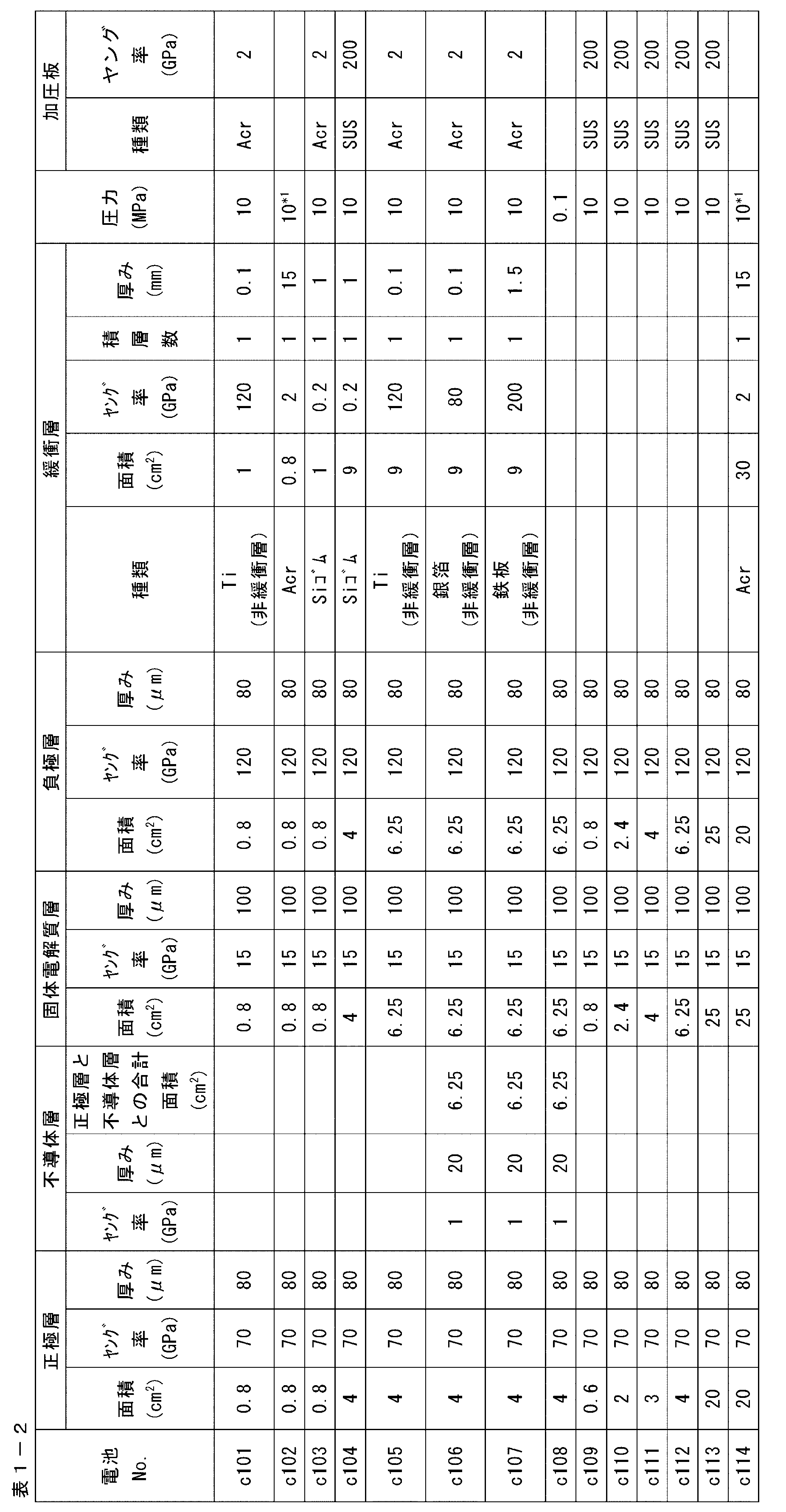
SiR:シリコンゴム(商品名:シリコンゴムシート1t、アズワン社製)
CFS:セルロースファイバーシート(商品名:PACOPADS、PACOTHANE TECHNOLOGIES社製)
厚紙(商品名:カルトナージュ厚紙)
PE:ポリエチレン(商品名:ポリエチレンフィルムシート軟質、(株式会社テックジャムより入手)
発泡ウレタン(商品名:低反発ウレタンシート、ミスミ社製)
PMMA:ポリメチルメタクリレート(商品名:PMMA-101005等、アズワン社製)
PI:ポリイミド(商品名:カプトン、東レデュポン社製)
Acr:アクリル板(商品名:アクリルプレート、ミスミ社製)
発泡PE:発泡ポリエチレン(商品名:発泡ポリエチレンシート、ミスミ社製)
木材(商品名:バルサ板)
銀箔(商品名:銀箔、ニラコ社製)
鉄板(商品名:スチールプレート、ミスミ社製)
上記で作製した全固体二次電池について、サイクル特性、放電負荷特性、及び高速充電特性を評価した。
上記で作製した全固体二次電池を用い、25℃の環境下、充電電流値を0.5mA/cm2とし、放電電流値を0.5mA/cm2として、4.2V~3.0Vの充放電を4回繰り返した。
その後、30℃の環境下、充電電流値2.5mA/cm2とし、放電電流値を2.5mA/cm2として、4.2V~3.0Vの充放電サイクルを繰り返した。
1サイクル目の放電容量と100サイクル目の放電容量とを測定し、下記式により算出した放電容量維持率(%)を下記評価基準に当てはめ評価した。
放電容量維持率(%)=100×[100サイクル目の放電容量]/[1サイクル目の放電容量]
-サイクル特性の評価基準-
A:放電容量維持率が71%以上
B:放電容量維持率が51%~70%
C:放電容量維持率が31%~50%
D:放電容量維持率が11%~30%
E:100サイクルに満たずに電池異常が生じた、又は、放電容量維持率が0%~10%
「電池異常」とは、充電時に3.5V~4.2V間の電池電圧を示す領域で、充電時に0.05V/sec以上の電池電圧の低下が認められる現象、又は、放電終了後の開回路電圧が2V以下を示す現象である。
上記で作製した全固体二次電池を用い、25℃の環境下、充電電流値0.5mA/cm2とし、放電電流値を0.5mA/cm2として、4.2V~3.0Vの充放電を4回繰り返した。
その後、25℃の環境下、充電電流値0.8mA/cm2として4.2Vまで充電し、次いで、放電電流値を0.8mA/cm2として3.0Vまで放電をした。その後、更に充電電流値を0.8mA/cm2として4.2Vまで充電し、次いで、放電電流値を8mA/cm2まで高めて3.0Vまで放電した。
放電電流値を0.8mA/cm2したときの放電容量(a1)と、放電電流値を8mA/cm2としたときの放電容量(a2)とを測定し、下記式により算出した放電容量維持率(%)を下記評価基準に当てはめ評価した。
放電容量維持率(%)=100×a2/a1
-放電負荷特性の評価基準-
A:放電容量維持率が71%以上
B:放電容量維持率が51%~70%
C:放電容量維持率が31%~50%
D:放電容量維持率が11%~30%
E:評価途中で電池異常が生じた、又は放電容量維持率が0%~10%
「電池異常」とは、充電時に3.5V~4.2V間の電池電圧を示す領域で、充電時に0.05V/sec以上の電池電圧の低下が認められる現象、又は、放電終了後の開回路電圧が2V以下を示す現象である。
放電容量維持率が高いほど、高放電電流値での放電を、低抵抗で、効率的に行えることを意味する。
上記で作製した全固体二次電池を用い、25℃の環境下、充電電流値0.5mA/cm2とし、放電電流値0.5mA/cm2として、4.2V~3.0Vの充放電を4回繰り返した。
その後、25℃の環境下、充電電流値0.8mA/cm2として4.2Vまで充電し、次いで、放電電流値を0.8mA/cm2として3.0Vまで放電をした。その後、更に充電電流値を8mA/cm2として4.2Vまで充電し、次いで、電流値が0.8mA/cm2となるまで4.2Vで定電圧充電を行った。その後、放電電流値0.8mA/cm2として3.0Vまで放電した。
充電電流値0.8mA/cm2としたときの充電容量(b1)と、充電電流値を8mA/cm2としたときの充電容量(b2)とを測定した。下記式により算出した充電容量維持率(%)を下記評価基準に当てはめ評価した。
充電容量維持率(%)=100×b2/b1
-高速充電特性の評価基準-
A:充電容量維持率が71%以上
B:充電容量維持率が51%~70%
C:充電容量維持率が31%~50%
D:充電容量維持率が11%~30%
E:評価途中で電池異常が生じた、又は充電容量維持率が0%~10%
「電池異常」とは、充電時に3.5V~4.2V間の電池電圧を示す領域で、充電時に0.05V/sec以上の電池電圧の低下が認められる現象、又は、放電終了後の開回路電圧が2V以下を示す現象である。
下表中、「性能向上率」とは、上記のサイクル特性において、基準電池に対して、サイクル特性評価が、上記評価基準に照らして3段階優れていたものをA、2段階優れていたものをB、1段階優れていたものをC、かわらないものをD、下がったものをEとして評価したものである。基準電池として、No.c109~113のうち、正極層の面積が同一のものを採用した。例えば、No.101の電池に対しては、No.c109の電池が基準電池となり、No.103の電池に対しては、No.c112が基準電池となる。
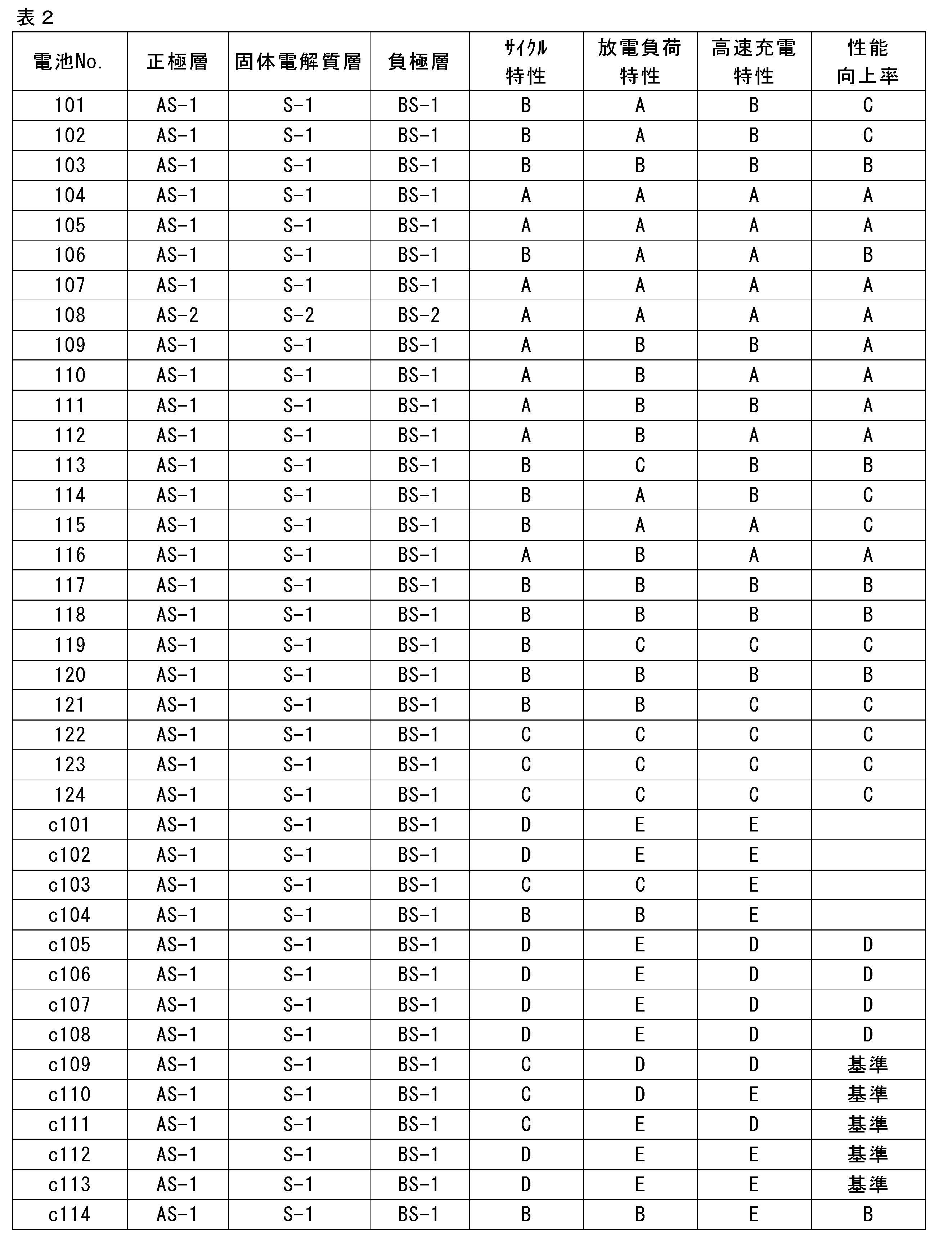
また、上記積層体が本発明で規定する関係:[正極層面積]<[負極層面積]≦[固体電解質層面積]を満たす場合でも、この積層体が緩衝層を介して加圧された状態にない場合、サイクル特性、放電負荷特性、及び高速充電特性の少なくともいずれにおいても劣る結果となった(No.c105~c113)。
また、上記積層体が[正極層面積]<[固体電解質層面積]を満たす場合でも、[負極層面積]≦[固体電解質層面積]を満たさない場合には、高速充電特性に劣る結果となった(No.c114)。
これに対し、本発明で規定する要件を満たす全固体二次電池はいずれも、サイクル特性、放電負荷特性、及び高速充電特性のすべてにおいて優れていた(No.101~124)。
さらに、性能向上率の結果から、緩衝層のヤング率が所定範囲にあり、かつ正極層の面積を4cm2以上とすることにより、サイクル特性の向上幅が大きくなることもわかる。これは、正極層の面積が一定の大きさを越えた場合に、圧力の面内のばらつきが大きくなるところを(圧力が集中する部位が生じやすくなり、また圧力が不足する部位が生じやすくなるところを)、緩衝層がそのばらつき効果的に抑える作用をしたためと考えられる。すなわち、本発明で規定する緩衝層を設けて加圧することにより、固体粒子により形成された、本来的にミクロレベルにおいて均一加圧が難しい層(この層は、充放電により膨張収縮を繰り返す層でもある。)を、ミクロのレベルでも均一に加圧することが可能になると考えられる。
2 負極活物質層
3 固体電解質層
4 正極活物質層
5 正極集電体
6 作動部位
10 積層体
11、11a、11b 緩衝層
12 正極層(正極集電体及び正極活物質層)
13 固体電解質層
14 負極層(負極集電体及び負極活物質層)
15、15a、15b 加圧板
Claims (11)
- 正極層と固体電解質層と負極層とをこの順に積層してなる積層体を有する全固体二次電池であって、
前記各層の面積が[正極層面積]<[負極層面積]≦[固体電解質層面積]を満たし、
前記正極層の前記固体電解質層側とは反対の面及び前記負極層の前記固体電解質層側とは反対の面の一方又は両方には、前記固体電解質層の面積よりも大面積で、前記正極層、前記固体電解質層及び前記負極層の各層よりもヤング率の小さな緩衝層を有し、
前記積層体が前記緩衝層を介した加圧状態にある全固体二次電池。 - 前記正極層の外周部に不導体層を有し、該正極層と該不導体層の面積の合計が前記負極層の面積と同じであるか、前記負極層の面積よりも大きく、かつ、前記緩衝層は前記不導体層よりもヤング率が小さい、請求項1記載の全固体二次電池。
- 前記不導体層、前記正極層、及び前記緩衝層の各厚さが、[不導体層厚]≦[正極層厚]≦[緩衝層厚]を満たす、請求項2記載の全固体二次電池。
- 前記正極層の面積が4cm2以上である、請求項1~3のいずれか1項記載の全固体二次電池。
- 前記緩衝層の厚さが、前記正極層、前記固体電解質層、及び前記負極層の各厚さの合計よりも厚い、請求項1~4のいずれか1項記載の全固体二次電池。
- 前記緩衝層の、前記積層体側とは反対の側に加圧板を有する、請求項1~5のいずれか1項記載の全固体二次電池。
- 前記正極層、固体電解質層、及び負極層の少なくとも1層が有機高分子化合物を含有する、請求項1~6のいずれか1項記載の全固体二次電池。
- 前記固体電解質が硫化物系固体電解質である、請求項1~7のいずれか1項記載の全固体二次電池。
- 前記緩衝層のヤング率が0.01GPa以上2GPa未満である、請求項1~8のいずれか1項記載の全固体二次電池。
- 前記加圧状態の圧力が0.1MPa以上60MPa以下である、請求項1~9のいずれか1項記載の全固体二次電池。
- 正極層と固体電解質層と負極層とをこの順に積層してなる積層体を有する全固体二次電池の製造方法であって、
前記各層の面積を[正極層面積]<[負極層面積]≦[固体電解質層面積]とし、
正極層の固体電解質層側とは反対の面及び負極層の固体電解質層側とは反対の面の一方又は両方には固体電解質層の面積よりも大面積で、正極層、固体電解質層及び負極層の各層よりもヤング率の小さな緩衝層を配し、
前記緩衝層を介して前記積層体を加圧することを含む、全固体二次電池の製造方法。
Priority Applications (5)
| Application Number | Priority Date | Filing Date | Title |
|---|---|---|---|
| EP19774974.0A EP3780239B1 (en) | 2018-03-28 | 2019-03-18 | All-solid state secondary battery and method of manufacturing the same |
| KR1020207022222A KR102449641B1 (ko) | 2018-03-28 | 2019-03-18 | 전고체 이차 전지 및 그 제조 방법 |
| CN201980013089.6A CN111712962B (zh) | 2018-03-28 | 2019-03-18 | 全固态二次电池及其制造方法 |
| JP2020510692A JP6912658B2 (ja) | 2018-03-28 | 2019-03-18 | 全固体二次電池及びその製造方法 |
| US16/987,403 US11909034B2 (en) | 2018-03-28 | 2020-08-07 | All-solid state secondary battery and method of manufacturing the same |
Applications Claiming Priority (2)
| Application Number | Priority Date | Filing Date | Title |
|---|---|---|---|
| JP2018062756 | 2018-03-28 | ||
| JP2018-062756 | 2018-03-28 |
Related Child Applications (1)
| Application Number | Title | Priority Date | Filing Date |
|---|---|---|---|
| US16/987,403 Continuation US11909034B2 (en) | 2018-03-28 | 2020-08-07 | All-solid state secondary battery and method of manufacturing the same |
Publications (1)
| Publication Number | Publication Date |
|---|---|
| WO2019188487A1 true WO2019188487A1 (ja) | 2019-10-03 |
Family
ID=68061543
Family Applications (1)
| Application Number | Title | Priority Date | Filing Date |
|---|---|---|---|
| PCT/JP2019/011142 Ceased WO2019188487A1 (ja) | 2018-03-28 | 2019-03-18 | 全固体二次電池及びその製造方法 |
Country Status (6)
| Country | Link |
|---|---|
| US (1) | US11909034B2 (ja) |
| EP (1) | EP3780239B1 (ja) |
| JP (1) | JP6912658B2 (ja) |
| KR (1) | KR102449641B1 (ja) |
| CN (1) | CN111712962B (ja) |
| WO (1) | WO2019188487A1 (ja) |
Cited By (17)
| Publication number | Priority date | Publication date | Assignee | Title |
|---|---|---|---|---|
| JP2021114361A (ja) * | 2020-01-16 | 2021-08-05 | パナソニック株式会社 | 蓄電装置及び蓄電モジュール |
| JP2021128845A (ja) * | 2020-02-12 | 2021-09-02 | パナソニック株式会社 | 非水電解質二次電池及び二次電池モジュール |
| WO2021225346A1 (ko) * | 2020-05-07 | 2021-11-11 | 삼성에스디아이 주식회사 | 전고체 전지 |
| JP2021177448A (ja) * | 2020-05-07 | 2021-11-11 | 三星エスディアイ株式会社Samsung SDI Co., Ltd. | 全固体二次電池 |
| WO2021229683A1 (ja) * | 2020-05-12 | 2021-11-18 | TeraWatt Technology株式会社 | 2次電池 |
| CN113782840A (zh) * | 2020-08-31 | 2021-12-10 | 蜂巢能源科技有限公司 | 一种全固态电芯及其制备方法和固态电池 |
| JP2022144855A (ja) * | 2021-03-19 | 2022-10-03 | 本田技研工業株式会社 | 全固体電池及び全固体電池の製造方法 |
| KR20220149580A (ko) * | 2020-03-27 | 2022-11-08 | 테라와트 테크놀로지 가부시키가이샤 | 고체 전지의 제조 방법 및 고체 전지 |
| CN115606014A (zh) * | 2020-06-04 | 2023-01-13 | Tdk电子股份有限公司(De) | 电化学电池和电化学系统 |
| JP2023541057A (ja) * | 2020-09-09 | 2023-09-27 | 三星エスディアイ株式会社 | 全固体電池 |
| JP2023165869A (ja) * | 2019-10-31 | 2023-11-17 | 株式会社村田製作所 | 二次電池および電池パック |
| JP2024088475A (ja) * | 2022-12-20 | 2024-07-02 | トヨタ自動車株式会社 | 電極体、固体電池及び固体電池の製造方法 |
| JP2024100240A (ja) * | 2023-01-13 | 2024-07-26 | トヨタ自動車株式会社 | 電極体、固体電池及び電極体の製造方法 |
| JP2024531303A (ja) * | 2022-02-21 | 2024-08-29 | エルジー エナジー ソリューション リミテッド | 電池セル加圧装置及びこれを含む電池セル充放電装置 |
| WO2025004950A1 (ja) * | 2023-06-29 | 2025-01-02 | 株式会社Gsユアサ | 全固体二次電池 |
| WO2025216060A1 (ja) * | 2024-04-12 | 2025-10-16 | マクセル株式会社 | 金型、発電素子およびその製造方法、並びに全固体電池およびその製造方法 |
| JP2025537656A (ja) * | 2023-10-30 | 2025-11-20 | エルジー エナジー ソリューション リミテッド | 二次電池用バッテリーセル |
Families Citing this family (18)
| Publication number | Priority date | Publication date | Assignee | Title |
|---|---|---|---|---|
| US11223088B2 (en) * | 2019-10-07 | 2022-01-11 | Bioenno Tech LLC | Low-temperature ceramic-polymer nanocomposite solid state electrolyte |
| KR102908004B1 (ko) * | 2020-10-12 | 2026-01-02 | 삼성에스디아이 주식회사 | 전고체 전지 |
| JP7299254B2 (ja) * | 2021-01-21 | 2023-06-27 | 本田技研工業株式会社 | 非水電解質二次電池 |
| CN112820934B (zh) * | 2021-02-09 | 2022-11-04 | 苏州清陶新能源科技有限公司 | 固态锂离子电池、基于固态锂离子电池的充电保护方法 |
| CN116529925A (zh) * | 2021-09-28 | 2023-08-01 | 株式会社Lg新能源 | 用于二次电池的电极组件和包括该电极组件的二次电池 |
| KR102857652B1 (ko) * | 2021-10-25 | 2025-09-08 | 삼성에스디아이 주식회사 | 전고체 전지 및 그 모듈 |
| KR102754050B1 (ko) * | 2022-01-20 | 2025-01-14 | 삼성에스디아이 주식회사 | 단위 스택셀 구조체 및 이를 포함하는 전고체 이차전지 |
| CN114430072B (zh) * | 2022-01-28 | 2023-06-30 | 蜂巢能源科技(无锡)有限公司 | 一种全固态电芯结构、其制备方法及全固态电芯组 |
| KR102904142B1 (ko) * | 2022-10-07 | 2025-12-23 | 삼성에스디아이 주식회사 | 온도 제어를 통한 전고체 이차 전지 모듈의 제조 방법 및 전고체 이차 전지 |
| KR102850375B1 (ko) * | 2022-12-27 | 2025-08-26 | 엘지전자 주식회사 | 전고체 배터리 시스템 |
| KR102925291B1 (ko) * | 2023-04-06 | 2026-02-06 | 삼성에스디아이 주식회사 | 전고체전지 모듈 및 그 제조 방법 |
| KR102893712B1 (ko) * | 2023-05-24 | 2025-11-28 | 삼성에스디아이 주식회사 | 전고체 전지용 탄성 시트 및 이를 포함하는 전고체 전지 |
| KR20250063183A (ko) | 2023-10-30 | 2025-05-08 | 주식회사 엘지에너지솔루션 | 전지 셀 가압 패드 및 이를 포함하는 전지 셀 가압 장치 |
| KR20250131129A (ko) * | 2024-02-26 | 2025-09-02 | 삼성에스디아이 주식회사 | 전고체 전지 및 이의 제조방법 |
| KR20250178095A (ko) * | 2024-06-18 | 2025-12-26 | 삼성에스디아이 주식회사 | 전고체 이차 전지용 탄성 시트 및 전고체 이차 전지 |
| CN118589111A (zh) * | 2024-08-07 | 2024-09-03 | 比亚迪股份有限公司 | 全固态电池、电池组和用电设备 |
| KR20260035515A (ko) * | 2024-09-06 | 2026-03-13 | 삼성전기주식회사 | 전고체 전지 |
| KR20260082980A (ko) * | 2024-11-28 | 2026-06-05 | 주식회사 엘지에너지솔루션 | 전고체 전지 구조체 및 이의 제조 방법 |
Citations (6)
| Publication number | Priority date | Publication date | Assignee | Title |
|---|---|---|---|---|
| JP2008103284A (ja) | 2006-10-20 | 2008-05-01 | Idemitsu Kosan Co Ltd | 全固体電池 |
| JP2014035888A (ja) * | 2012-08-09 | 2014-02-24 | Toyota Motor Corp | 全固体電池及びその製造方法 |
| JP2014120199A (ja) * | 2012-12-12 | 2014-06-30 | Samsung R&D Institute Japan Co Ltd | 固体電池 |
| JP2014120372A (ja) * | 2012-12-18 | 2014-06-30 | Toyota Motor Corp | 全固体電池及びその製造方法 |
| US20170040644A1 (en) * | 2014-04-22 | 2017-02-09 | Bayerische Motoren Werke Aktiengesellschaft | Galvanic Element Having Solid-State Cell Stack |
| JP2018062756A (ja) | 2016-10-12 | 2018-04-19 | 株式会社京三製作所 | 床面式表示器 |
Family Cites Families (9)
| Publication number | Priority date | Publication date | Assignee | Title |
|---|---|---|---|---|
| JPS5131283B1 (ja) | 1966-01-26 | 1976-09-06 | ||
| WO2010131321A1 (ja) | 2009-05-11 | 2010-11-18 | トヨタ自動車株式会社 | 固体電池の製造方法及び固体電池 |
| JP2010272266A (ja) * | 2009-05-20 | 2010-12-02 | Tokai Rubber Ind Ltd | リチウムイオン電池用電極部材、リチウムイオン電池およびその製造方法 |
| JP5636965B2 (ja) * | 2011-01-05 | 2014-12-10 | トヨタ自動車株式会社 | リチウムイオン二次電池用電極体の製造方法、及びリチウムイオン二次電池の製造方法 |
| WO2012141231A1 (ja) * | 2011-04-15 | 2012-10-18 | 株式会社 村田製作所 | 固体電池 |
| JP2013243004A (ja) * | 2012-05-18 | 2013-12-05 | Toyota Motor Corp | 固体電池、及び固体電池の製造方法 |
| JP2014127272A (ja) * | 2012-12-25 | 2014-07-07 | Toyota Motor Corp | 全固体電池用電極体の製造方法 |
| US9837684B2 (en) * | 2015-02-19 | 2017-12-05 | Samsung Electronics Co., Ltd. | All solid secondary battery and method of manufacturing the same |
| JP7053162B2 (ja) * | 2017-04-05 | 2022-04-12 | トヨタ自動車株式会社 | 積層電池モジュール |
-
2019
- 2019-03-18 JP JP2020510692A patent/JP6912658B2/ja active Active
- 2019-03-18 EP EP19774974.0A patent/EP3780239B1/en active Active
- 2019-03-18 CN CN201980013089.6A patent/CN111712962B/zh active Active
- 2019-03-18 WO PCT/JP2019/011142 patent/WO2019188487A1/ja not_active Ceased
- 2019-03-18 KR KR1020207022222A patent/KR102449641B1/ko active Active
-
2020
- 2020-08-07 US US16/987,403 patent/US11909034B2/en active Active
Patent Citations (6)
| Publication number | Priority date | Publication date | Assignee | Title |
|---|---|---|---|---|
| JP2008103284A (ja) | 2006-10-20 | 2008-05-01 | Idemitsu Kosan Co Ltd | 全固体電池 |
| JP2014035888A (ja) * | 2012-08-09 | 2014-02-24 | Toyota Motor Corp | 全固体電池及びその製造方法 |
| JP2014120199A (ja) * | 2012-12-12 | 2014-06-30 | Samsung R&D Institute Japan Co Ltd | 固体電池 |
| JP2014120372A (ja) * | 2012-12-18 | 2014-06-30 | Toyota Motor Corp | 全固体電池及びその製造方法 |
| US20170040644A1 (en) * | 2014-04-22 | 2017-02-09 | Bayerische Motoren Werke Aktiengesellschaft | Galvanic Element Having Solid-State Cell Stack |
| JP2018062756A (ja) | 2016-10-12 | 2018-04-19 | 株式会社京三製作所 | 床面式表示器 |
Non-Patent Citations (3)
| Title |
|---|
| A. HAYASHIS. HAMAH. MORIMOTOM. TATSUMISAGOT. MINAMI, CHEM. LETT., 2001, pages 872,873 |
| See also references of EP3780239A4 |
| T. OHTOMOA. HAYASHIM. TATSUMISAGOY. TSUCHIDAS. HAMGAK. KAWAMOTO, JOURNAL OF POWER SOURCES, vol. 233, 2013, pages 231 - 235 |
Cited By (38)
| Publication number | Priority date | Publication date | Assignee | Title |
|---|---|---|---|---|
| JP2023165869A (ja) * | 2019-10-31 | 2023-11-17 | 株式会社村田製作所 | 二次電池および電池パック |
| JP2021114361A (ja) * | 2020-01-16 | 2021-08-05 | パナソニック株式会社 | 蓄電装置及び蓄電モジュール |
| JP7383501B2 (ja) | 2020-01-16 | 2023-11-20 | パナソニックホールディングス株式会社 | 蓄電装置及び蓄電モジュール |
| JP2021128845A (ja) * | 2020-02-12 | 2021-09-02 | パナソニック株式会社 | 非水電解質二次電池及び二次電池モジュール |
| JP7403337B2 (ja) | 2020-02-12 | 2023-12-22 | パナソニックホールディングス株式会社 | 非水電解質二次電池及び二次電池モジュール |
| CN115362588A (zh) * | 2020-03-27 | 2022-11-18 | 特拉沃特科技株式会社 | 固体电池的制造方法以及固体电池 |
| KR102863319B1 (ko) * | 2020-03-27 | 2025-09-23 | 테라와트 테크놀로지 가부시키가이샤 | 고체 전지의 제조 방법 및 고체 전지 |
| KR20220149580A (ko) * | 2020-03-27 | 2022-11-08 | 테라와트 테크놀로지 가부시키가이샤 | 고체 전지의 제조 방법 및 고체 전지 |
| US12658467B2 (en) | 2020-05-07 | 2026-06-16 | Samsung Sdi Co., Ltd. | All-solid-state battery |
| WO2021225346A1 (ko) * | 2020-05-07 | 2021-11-11 | 삼성에스디아이 주식회사 | 전고체 전지 |
| JP2021177448A (ja) * | 2020-05-07 | 2021-11-11 | 三星エスディアイ株式会社Samsung SDI Co., Ltd. | 全固体二次電池 |
| CN115552686A (zh) * | 2020-05-07 | 2022-12-30 | 三星Sdi株式会社 | 全固态电池 |
| CN115552686B (zh) * | 2020-05-07 | 2026-04-28 | 三星Sdi株式会社 | 全固态电池 |
| JP7609569B2 (ja) | 2020-05-07 | 2025-01-07 | 三星エスディアイ株式会社 | 全固体二次電池 |
| JPWO2021229683A1 (ja) * | 2020-05-12 | 2021-11-18 | ||
| EP4152468A4 (en) * | 2020-05-12 | 2024-12-04 | Terawatt Technology K.K. | SECONDARY BATTERY |
| JP7359490B2 (ja) | 2020-05-12 | 2023-10-11 | TeraWatt Technology株式会社 | 2次電池 |
| WO2021229683A1 (ja) * | 2020-05-12 | 2021-11-18 | TeraWatt Technology株式会社 | 2次電池 |
| CN115516690A (zh) * | 2020-05-12 | 2022-12-23 | 特拉沃特科技株式会社 | 二次电池 |
| CN115606014A (zh) * | 2020-06-04 | 2023-01-13 | Tdk电子股份有限公司(De) | 电化学电池和电化学系统 |
| JP2023527921A (ja) * | 2020-06-04 | 2023-06-30 | テーデーカー エレクトロニクス アーゲー | 電気化学セル及び電気化学システム |
| JP7528269B2 (ja) | 2020-06-04 | 2024-08-05 | テーデーカー エレクトロニクス アーゲー | 電気化学セル及び電気化学システム |
| US20230223532A1 (en) * | 2020-06-04 | 2023-07-13 | Tdk Electronics Ag | Electrochemical Cell and Electrochemical System |
| CN113782840B (zh) * | 2020-08-31 | 2023-11-28 | 蜂巢能源科技有限公司 | 一种全固态电芯及其制备方法和固态电池 |
| CN113782840A (zh) * | 2020-08-31 | 2021-12-10 | 蜂巢能源科技有限公司 | 一种全固态电芯及其制备方法和固态电池 |
| JP7596517B2 (ja) | 2020-09-09 | 2024-12-09 | 三星エスディアイ株式会社 | 全固体電池 |
| JP2023541057A (ja) * | 2020-09-09 | 2023-09-27 | 三星エスディアイ株式会社 | 全固体電池 |
| US12278340B2 (en) | 2021-03-19 | 2025-04-15 | Honda Motor Co., Ltd. | All-solid-state battery and method of producing all-solid-state battery |
| JP2022144855A (ja) * | 2021-03-19 | 2022-10-03 | 本田技研工業株式会社 | 全固体電池及び全固体電池の製造方法 |
| JP2024531303A (ja) * | 2022-02-21 | 2024-08-29 | エルジー エナジー ソリューション リミテッド | 電池セル加圧装置及びこれを含む電池セル充放電装置 |
| JP7859700B2 (ja) | 2022-02-21 | 2026-05-15 | エルジー エナジー ソリューション リミテッド | 電池セル加圧装置及びこれを含む電池セル充放電装置 |
| JP2024088475A (ja) * | 2022-12-20 | 2024-07-02 | トヨタ自動車株式会社 | 電極体、固体電池及び固体電池の製造方法 |
| JP7754077B2 (ja) | 2022-12-20 | 2025-10-15 | トヨタ自動車株式会社 | 電極体、固体電池及び固体電池の製造方法 |
| JP2024100240A (ja) * | 2023-01-13 | 2024-07-26 | トヨタ自動車株式会社 | 電極体、固体電池及び電極体の製造方法 |
| JP7700805B2 (ja) | 2023-01-13 | 2025-07-01 | トヨタ自動車株式会社 | 電極体、固体電池及び電極体の製造方法 |
| WO2025004950A1 (ja) * | 2023-06-29 | 2025-01-02 | 株式会社Gsユアサ | 全固体二次電池 |
| JP2025537656A (ja) * | 2023-10-30 | 2025-11-20 | エルジー エナジー ソリューション リミテッド | 二次電池用バッテリーセル |
| WO2025216060A1 (ja) * | 2024-04-12 | 2025-10-16 | マクセル株式会社 | 金型、発電素子およびその製造方法、並びに全固体電池およびその製造方法 |
Also Published As
| Publication number | Publication date |
|---|---|
| EP3780239A4 (en) | 2021-05-19 |
| CN111712962B (zh) | 2024-09-03 |
| KR102449641B1 (ko) | 2022-09-29 |
| US11909034B2 (en) | 2024-02-20 |
| KR20200103806A (ko) | 2020-09-02 |
| JPWO2019188487A1 (ja) | 2020-12-03 |
| EP3780239A1 (en) | 2021-02-17 |
| CN111712962A (zh) | 2020-09-25 |
| US20200373565A1 (en) | 2020-11-26 |
| JP6912658B2 (ja) | 2021-08-04 |
| EP3780239B1 (en) | 2024-07-31 |
Similar Documents
| Publication | Publication Date | Title |
|---|---|---|
| JP6912658B2 (ja) | 全固体二次電池及びその製造方法 | |
| KR102126144B1 (ko) | 고체 전해질 조성물, 전고체 이차 전지용 전극 시트 및 전고체 이차 전지와, 전고체 이차 전지용 전극 시트 및 전고체 이차 전지의 제조 방법 | |
| KR102501561B1 (ko) | 전고체 리튬 이온 이차 전지와 그 제조 방법, 및 부극용 적층 시트 | |
| JP6860681B2 (ja) | 全固体二次電池、全固体二次電池用外装材及び全固体二次電池の製造方法 | |
| JP6948382B2 (ja) | 全固体二次電池及びその製造方法、並びに全固体二次電池用固体電解質シート及び全固体二次電池用正極活物質シート | |
| JP7059302B2 (ja) | 固体電解質組成物、固体電解質含有シート及び全固体二次電池、並びに、固体電解質含有シート及び全固体二次電池の製造方法 | |
| JP6572063B2 (ja) | 全固体二次電池、全固体二次電池用電極シート及びこれらの製造方法 | |
| JP7064613B2 (ja) | 全固体二次電池用積層部材の製造方法及び全固体二次電池の製造方法 | |
| JP7014899B2 (ja) | 固体電解質含有シート、全固体二次電池用電極シート、全固体二次電池、電子機器及び電気自動車、並びに、これらの製造方法 | |
| WO2017199821A1 (ja) | 固体電解質組成物、固体電解質含有シートおよび全固体二次電池ならびに固体電解質含有シートおよび全固体二次電池の製造方法 | |
| JPWO2020203545A1 (ja) | 複合電極活物質、電極用組成物、全固体二次電池用電極シート及び全固体二次電池、並びに、複合電極活物質、全固体二次電池用電極シート及び全固体二次電池の製造方法 | |
| JP7119214B2 (ja) | 全固体二次電池及びその製造方法 | |
| JP6665343B2 (ja) | 無機固体電解質材料、並びに、これを用いたスラリー、全固体二次電池用固体電解質膜、全固体二次電池用固体電解質シート、全固体二次電池用正極活物質膜、全固体二次電池用負極活物質膜、全固体二次電池用電極シート、全固体二次電池及び全固体二次電池の製造方法 | |
| WO2022202901A1 (ja) | 固体電解質積層シート及び全固体二次電池、並びに、全固体二次電池の製造方法 | |
| JP6673785B2 (ja) | 固体電解質組成物、固体電解質含有シートおよび全固体二次電池ならびに固体電解質含有シートおよび全固体二次電池の製造方法 | |
| JP6670641B2 (ja) | 電極用材料、これを用いた全固体二次電池用電極シートおよび全固体二次電池ならびに全固体二次電池用電極シートおよび全固体二次電池の製造方法 | |
| WO2018164051A1 (ja) | 全固体二次電池及びその製造方法、並びに全固体二次電池用固体電解質膜及びその製造方法 | |
| JP2022169698A (ja) | 固体電解質組成物、固体電解質含有シート及び全固体二次電池並びに固体電解質含有シート及び全固体二次電池の製造方法 | |
| JP6631363B2 (ja) | 負極活物質、負極活物質を含む負極及び負極を含むリチウムイオン二次電池 |
Legal Events
| Date | Code | Title | Description |
|---|---|---|---|
| 121 | Ep: the epo has been informed by wipo that ep was designated in this application |
Ref document number: 19774974 Country of ref document: EP Kind code of ref document: A1 |
|
| ENP | Entry into the national phase |
Ref document number: 2020510692 Country of ref document: JP Kind code of ref document: A |
|
| ENP | Entry into the national phase |
Ref document number: 20207022222 Country of ref document: KR Kind code of ref document: A |
|
| NENP | Non-entry into the national phase |
Ref country code: DE |
|
| ENP | Entry into the national phase |
Ref document number: 2019774974 Country of ref document: EP Effective date: 20201028 |