WO2019188530A1 - Dispositif et procédé de support à la recherche et support d'enregistrement lisible par ordinateur - Google Patents
Dispositif et procédé de support à la recherche et support d'enregistrement lisible par ordinateur Download PDFInfo
- Publication number
- WO2019188530A1 WO2019188530A1 PCT/JP2019/011300 JP2019011300W WO2019188530A1 WO 2019188530 A1 WO2019188530 A1 WO 2019188530A1 JP 2019011300 W JP2019011300 W JP 2019011300W WO 2019188530 A1 WO2019188530 A1 WO 2019188530A1
- Authority
- WO
- WIPO (PCT)
- Prior art keywords
- search
- target
- estimated
- information
- probability
- Prior art date
- Legal status (The legal status is an assumption and is not a legal conclusion. Google has not performed a legal analysis and makes no representation as to the accuracy of the status listed.)
- Ceased
Links
Images


Classifications
-
- F—MECHANICAL ENGINEERING; LIGHTING; HEATING; WEAPONS; BLASTING
- F41—WEAPONS
- F41G—WEAPON SIGHTS; AIMING
- F41G9/00—Systems for controlling missiles or projectiles, not provided for elsewhere
- F41G9/002—Systems for controlling missiles or projectiles, not provided for elsewhere for guiding a craft to a correct firing position
- F41G9/006—Systems for controlling missiles or projectiles, not provided for elsewhere for guiding a craft to a correct firing position for torpedo launchers
-
- B—PERFORMING OPERATIONS; TRANSPORTING
- B63—SHIPS OR OTHER WATERBORNE VESSELS; RELATED EQUIPMENT
- B63B—SHIPS OR OTHER WATERBORNE VESSELS; EQUIPMENT FOR SHIPPING
- B63B49/00—Arrangements of nautical instruments or navigational aids
-
- F—MECHANICAL ENGINEERING; LIGHTING; HEATING; WEAPONS; BLASTING
- F41—WEAPONS
- F41G—WEAPON SIGHTS; AIMING
- F41G7/00—Direction control systems for self-propelled missiles
- F41G7/20—Direction control systems for self-propelled missiles based on continuous observation of target position
- F41G7/22—Homing guidance systems
- F41G7/224—Deceiving or protecting means
-
- G—PHYSICS
- G01—MEASURING; TESTING
- G01C—MEASURING DISTANCES, LEVELS OR BEARINGS; SURVEYING; NAVIGATION; GYROSCOPIC INSTRUMENTS; PHOTOGRAMMETRY OR VIDEOGRAMMETRY
- G01C21/00—Navigation; Navigational instruments not provided for in groups G01C1/00 - G01C19/00
- G01C21/20—Instruments for performing navigational calculations
-
- G—PHYSICS
- G01—MEASURING; TESTING
- G01S—RADIO DIRECTION-FINDING; RADIO NAVIGATION; DETERMINING DISTANCE OR VELOCITY BY USE OF RADIO WAVES; LOCATING OR PRESENCE-DETECTING BY USE OF THE REFLECTION OR RERADIATION OF RADIO WAVES; ANALOGOUS ARRANGEMENTS USING OTHER WAVES
- G01S15/00—Systems using the reflection or reradiation of acoustic waves, e.g. sonar systems
- G01S15/88—Sonar systems specially adapted for specific applications
- G01S15/89—Sonar systems specially adapted for specific applications for mapping or imaging
-
- G—PHYSICS
- G08—SIGNALLING
- G08G—TRAFFIC CONTROL SYSTEMS
- G08G3/00—Traffic control systems for marine craft
-
- F—MECHANICAL ENGINEERING; LIGHTING; HEATING; WEAPONS; BLASTING
- F41—WEAPONS
- F41G—WEAPON SIGHTS; AIMING
- F41G7/00—Direction control systems for self-propelled missiles
- F41G7/20—Direction control systems for self-propelled missiles based on continuous observation of target position
- F41G7/22—Homing guidance systems
- F41G7/2246—Active homing systems, i.e. comprising both a transmitter and a receiver
-
- F—MECHANICAL ENGINEERING; LIGHTING; HEATING; WEAPONS; BLASTING
- F41—WEAPONS
- F41G—WEAPON SIGHTS; AIMING
- F41G7/00—Direction control systems for self-propelled missiles
- F41G7/20—Direction control systems for self-propelled missiles based on continuous observation of target position
- F41G7/22—Homing guidance systems
- F41G7/2273—Homing guidance systems characterised by the type of waves
- F41G7/228—Homing guidance systems characterised by the type of waves using acoustic waves, e.g. for torpedoes
-
- G—PHYSICS
- G01—MEASURING; TESTING
- G01S—RADIO DIRECTION-FINDING; RADIO NAVIGATION; DETERMINING DISTANCE OR VELOCITY BY USE OF RADIO WAVES; LOCATING OR PRESENCE-DETECTING BY USE OF THE REFLECTION OR RERADIATION OF RADIO WAVES; ANALOGOUS ARRANGEMENTS USING OTHER WAVES
- G01S7/00—Details of systems according to groups G01S13/00, G01S15/00, G01S17/00
- G01S7/52—Details of systems according to groups G01S13/00, G01S15/00, G01S17/00 of systems according to group G01S15/00
- G01S7/537—Counter-measures or counter-counter-measures, e.g. jamming, anti-jamming
Definitions
- the present invention relates to a search support device and a search support method for calculating a search route, and further relates to a computer-readable recording medium in which a program for realizing these is recorded.
- a system that uses sensors in vehicles to search for targets is used.
- these systems that are used at sea, in the sea, and in the air, regardless of whether the vehicle is manned or unmanned, a method is adopted in which the operator manually inputs waypoints to determine the movement route.
- a route is determined by route search represented by car navigation of automobiles.
- Patent Document 1 discloses a flight path search device that searches for an optimal flight path in a combat aircraft.
- the map data is divided into a plurality of grids in the horizontal plane, and the points related to the degree of attack avoidance of each of the plurality of grids are calculated based on the map data and the enemy power range information.
- a flight path from the mission start position to the attack position is searched based on the number of points on the plurality of grids.
- Patent Document 2 discloses a flight plan planning device for planning a flight plan so as to avoid misfire of a friend up to a target position. According to the flight plan planning device, a flight plan is drafted based on flight path information, weather information, and threat information.
- Patent Document 3 discloses an operation support system for calculating a route for minimizing fuel consumption for a ship.
- Patent Documents 1 and 2 the flight route is calculated, but the search route is set up to the position of the target according to the surrounding environment using the above-described sensor. No calculation is disclosed. Also in Patent Document 3, although the navigation route is calculated, it is not disclosed that the search route is calculated up to the position of the target according to the surrounding environment using the sensor as described above. Furthermore, Patent Documents 1 to 3 do not disclose moving from a threat target to the position of the target while suppressing its own detection.
- An example of an object of the present invention is to provide a search support device, a search support method, and a search support program for calculating a search route to a target position according to the surrounding environment and a threat target.
- a search support device includes: Search sensor means for searching for a target; Environmental sensor means for measuring the surrounding environment and generating environmental information based on the measurement results; A search effective range estimation means for estimating a search effective range of the search sensor means using the environment information and performance information indicating the performance of the search sensor means, A threat effective range estimation means for estimating a search effective range of a sensor held by the target object using the environment information and performance information indicating the performance of the sensor held by the threat target object; A search route to the target is calculated based on a search effective range of the search sensor means, a search effective range of a sensor held by the target, and a distribution of existence probabilities of the threat target. Route calculation means; It is characterized by having.
- a search support method includes: (A) The search of the search sensor unit using the environmental information generated by measuring the surrounding environment by the environment sensor unit and based on the measurement result and the performance information indicating the performance of the search sensor unit searching for the target Estimate the effective range, (B) Using the environmental information and performance information indicating the performance of the sensor held by the threat object, the search effective range of the sensor held by the object is estimated, (C) Based on the search effective range of the search sensor unit, the search effective range of the sensor possessed by the target object, and the distribution of the probability of existence of the target object as the threat, the search path to the target object is determined. calculate, It is characterized by that.
- a computer-readable recording medium recording a program according to one aspect of the present invention.
- C Based on the search effective range of the search sensor unit, the search effective range of the sensor possessed by the target object, and the distribution of the probability of existence of the target object as the threat, the search path to the target object is determined. Calculating, steps, A program including an instruction for executing is recorded.
- the search route to the target position can be calculated according to the surrounding environment and the threatening object.
- FIG. 1 is a diagram illustrating an example of a search support apparatus.
- FIG. 2 is a diagram illustrating an example of a search support system having a search support device.
- FIG. 3 is a specific diagram of the search support system.
- FIG. 4 is a diagram for explaining the detection probability of the target.
- FIG. 5 is a diagram for explaining the detection probability from the target object as a threat.
- FIG. 6 is a diagram illustrating an example of a search route display.
- FIG. 7 is a diagram showing fluctuations in the detection probability requirement and the detected probability requirement.
- FIG. 8 is a diagram illustrating an example of an operation for calculating a search route.
- FIG. 9 is a diagram illustrating an example of an operation for calculating a movement cost.
- FIG. 10 is a diagram illustrating an example of a computer that implements the search support apparatus.
- Embodiment 1 of the present invention will be described below with reference to FIGS.
- FIG. 1 is a diagram illustrating an example of a search support apparatus.
- the search support device 1 in the present embodiment shown in FIG. 1 is a device that calculates a search route to a target position in accordance with the surrounding environment and a threat target.
- the search support device 1 includes a search sensor unit 2, an environment sensor unit 3, a search effective range estimation unit 4, a threat effective range estimation unit 5, and a route calculation unit 6.
- the target position may be a peripheral range including the target position.
- the search sensor unit 2 searches for a target.
- the environment sensor unit 3 measures the surrounding environment and generates environment information based on the measurement result.
- the search effective range estimation unit 4 estimates the search effective range of the search sensor unit 2 using environment information and performance information indicating the performance of the search sensor unit 2.
- the threat effective range estimation unit 5 estimates the threat effective range of the sensor held by the target using the environment information and the performance information indicating the performance of the sensor held by the target as the threat.
- the route calculation unit 6 calculates a search route to the target based on the search effective range of the search sensor unit 2, the search effective range of the sensor held by the target, and the distribution of the existence probability of the target threat. calculate.
- the search effective range of the search sensor unit 2 the effective search range of the sensor held by the target object, and the distribution of the existence probability of the target object that is a threat
- the search route can be calculated. Therefore, for example, even when a sensor that is susceptible to the influence of the surrounding environment is mounted on the vehicle, the search route to the target position can be calculated according to the surrounding environment and the threatening object. As a result, even if the sensor mounted on the vehicle uses a sensor that is easily influenced by the surrounding environment, it is possible to calculate a search route that is highly optimal for the purpose of the mission.
- FIG. 2 is a diagram illustrating an example of a search support system having a search support device.
- the search support system 20 in the present embodiment includes a database station 101 and a vehicle 110.
- the database station 101 is a facility where a database is installed, for example.
- the database station 101 includes a threat target information database 102, a wide area target information database 103, a wide area environment information database 104, a wide area risk information database 105, and a communication device 106.
- the threat target information database 102 stores information indicating the performance of the sensor held by the threat target.
- the wide area target information database 103 includes information indicating the presence of a target acquired from outside the search support system 20.
- the wide area environment information database 104 includes environment information obtained by measuring the surrounding environment acquired from outside the search support system 20. In other words, the environmental information is information used for calculating the performance of the sensor or the movement performance of the vehicle.
- the wide area risk information database 105 includes information indicating the presence of a target object that is a threat acquired from outside the search support system 20.
- the communication device 106 transmits the data included in these databases 102 to 105 via the communication device 114 of the vehicle 110.
- the vehicle 110 is a movable vehicle.
- the vehicle 110 includes a parameter input device 111, a search sensor device 112 (search sensor unit 2), an environment information acquisition sensor device 113 (environment sensor unit 3), a communication device 114, and a search support device 115 (search effective range estimation).
- a search support device 1) having a unit 4, a threat effective range estimation unit 5 and a route calculation unit 6, and a display device 116.
- the parameter input device 111 sets parameter values according to the purpose of the mission.
- the search sensor device 112 searches for a target set by the mission and generates target information for the target.
- the environmental information acquisition sensor device 113 generates environmental information used for calculation of sensor performance or vehicle movement performance. For example, it is information relating to surrounding sensor capabilities and vehicle movement performance.
- the communication device 114 receives data from the database station 101 via the communication device 106.
- the search support device 115 calculates a search route.
- the display device 116 displays the calculated search route.
- FIG. 3 is a specific diagram of the search support system.
- a vehicle 110 includes a parameter input device 201 (111), a search sensor device 202 (112: sonar), an environment information acquisition sensor device 203 (113), a database station 204 (101), and a search support device 205 (115).
- Display device 206 (116).
- the parameter input device 201 inputs start / end position setting information 210, speed setting information 211, and mission setting information 212 to the search support device 205.
- the start / end position setting information 210 includes information indicating the start position and the end position of the search by the vehicle 110.
- the speed setting information 211 is information for setting the speed of the vehicle 110. In addition, you may have a some setting value.
- the mission setting information 212 is information having a required degree of detection probability of a target object regarding a mission to be executed, a required degree of detection probability from a target object that is a threat, and a required degree of mission execution time.
- the degree of request is a value representing the importance of each parameter in the mission to be executed, and is used as a weight in calculating the search route. For example, if the target detection probability is set high and the target detection probability is low, the target is easy to detect, but the threat target detects it.
- the route that is likely to be calculated is calculated.
- the search sensor device 202 is a device that acquires sound wave information and performs signal processing, information processing, and the like on the acquired sound wave information. In addition, the search sensor device 202 inputs target information (target position information 220, target motion information 221) to the search support device 205.
- the target position information 220 is information indicating the distribution and accuracy of the detected position of the target object.
- the target motion information 221 is information indicating the distribution of the moving direction and moving speed of the target.
- the environment information acquisition sensor device 203 outputs the ambient underwater sound velocity information 230 and the ambient flow velocity information 231 to the search support device 205.
- the ambient underwater sound speed information 230 includes information indicating the water temperature acquired using the underwater sensor, information indicating the vertical profile of the underwater sound speed calculated from the electrical conductivity, and the like.
- the ambient flow velocity information 231 is information indicating the velocity vector of the surrounding water flow acquired using the underwater sensor.
- the database station 204 sends the threat target sensor performance information 240, the wide area target position information 241, the wide area underwater sound speed information 242, the wide area flow velocity information 243, and the wide area risk information 244 to the search support apparatus 205, and the communication apparatus 106. Send through.
- the threat target sensor performance information 240 is information received from the database station 204 and indicating the performance of the sensor possessed by the target object that is the threat of the vehicle 110.
- the wide area target position information 241 is information indicating the distribution of the presence probability of the target of the vehicle 110.
- the wide-area underwater sound speed information 242 is information indicating the underwater sound speed distribution of the entire area searched in the mission.
- the wide area flow velocity information 243 is information indicating the flow velocity distribution of the entire area searched in the mission.
- the wide area risk information 244 is information indicating the distribution of the existence probability of the target object as a threat.
- the search support device 205 uses the information acquired from the parameter input device 201, the search sensor device 202, the environment information acquisition sensor device 203, and the database station 204, and provides route information, detection probability information, and detection probability. Information.
- the search support apparatus 205 includes a search route calculation unit 250, a sensor performance estimation unit 251, a target position estimation unit 252, an underwater sound speed estimation unit 253, a flow velocity estimation unit 254, search sensor capability data 255, and terrain data 256. And have. Further, the search support device 205 includes a detection probability calculation unit 261, a detected probability calculation unit 262, a movement cost calculation unit 263, and a display information generation unit 264.
- the search route calculation unit 250 includes information acquired from the sensor performance estimation unit 251 (search effective range estimation unit 4, threat effective range estimation unit 5), target position estimation unit 252, flow velocity estimation unit 254, wide area risk information 244, The search route is searched using the information of the terrain data 256, and the route information is calculated.
- the search route calculation unit 250 selects one search condition parameter. Subsequently, the search route calculation unit 250 calculates a range in which the search route is a search target for the selected search condition parameter.
- the search route calculation unit 250 is set by the search condition parameter. Only the range that can be reached within the mission execution time is set as the route search range.
- the search route calculation unit 250 performs grid division processing, which will be described later, on the route search range in order to generate a cell that uses the search route in the search.
- the grid interval may be a fixed value or a variable value.
- the search route calculation unit 250 executes search route calculation processing from the start position to the end position set by the search condition parameter.
- the search route calculation process uses a Dijkstra method, an A * (A-Star) method, or the like, which is a route search algorithm that can set an individual travel cost for a search route.
- the movement cost is a value indicating a virtual cost necessary for movement depending on a preset request degree.
- calculation is performed based on the detection probability of the target and the detection probability from the target object that is a threat, based on the time required for movement. For example, when the required degree of target detection probability is set high, a route on which a target can be easily detected has a lower movement cost. Further, when the degree of detection probability of the detection target from the threat object is set high, a route that is easily detected from the threat has a higher movement cost.
- the route information is information indicating a search route from the start position where the search is started to the end position where the search is ended.
- the detection probability information is information indicating a range in which the vehicle 110 can detect the target object to be searched and the detection probability.
- the detection probability information is information indicating a range in which the vehicle 110 is detected from a threat object and a detection probability.
- the search effective range estimation unit 4 included in the sensor performance estimation unit 251 uses, for example, input data acquired from the underwater sound speed estimation unit 253, search sensor capability data 255, and terrain data 256, and a search sensor device for input data.
- the threat effective range estimation unit 5 included in the sensor performance estimation unit 251 uses, for example, input data acquired from the underwater sound speed estimation unit 253, threat target sensor performance information 240, and terrain data 256 to input data. Estimate the sonar performance of the threat object.
- the sensor performance estimation unit 251 acquires the speed setting information 211 when the performance of the search sensor device 202 changes depending on the speed of the vehicle 110, adds the acquired speed setting information 211, and estimates the sonar performance. Good.
- the target position estimation unit 252 receives input data acquired from the wide area target position information 241 in addition to the estimated position information of the target detected by the search sensor device 202 at the specified date and time calculated from the target position information 220 and the target motion information 221. To calculate the distribution of the existence probability of the target in a wide area.
- the underwater sound speed estimation unit 253 calculates the estimated value of the underwater sound speed distribution by correcting the wide area underwater sound speed information 242 with the surrounding underwater sound speed information 230.
- the flow velocity estimation unit 254 calculates the estimated value of the flow velocity distribution by correcting the wide area flow velocity information 243 with the ambient flow velocity information 231.
- the detection probability calculation unit 261 uses environment information to estimate the arrival date and time to reach the estimated target position, and uses the target information to estimate the distribution of the existence probability of the target object at the arrival date and time. In addition, the detection probability calculation unit 261 uses the environment information to estimate the environment of the estimated target position at the arrival date and time, and uses the estimated distribution of the existence probability of the target object and the environment of the estimated target position, The detection probability of the target at the estimated target position at the arrival date and time is calculated.
- the detection probability calculation unit 261 first uses the environment information such as the current velocity information of the ocean current to determine the arrival date and time to reach the estimated target position and the travel time to reach the estimated target position. presume. Subsequently, the detection probability calculation unit 261, based on the target position estimated using the target position information 220 and the target motion information 221, and the wide area target position information 241, the target object at the estimated target position at the arrival date and time. The distribution of existence probability is calculated. In addition, the detection probability calculation unit 261 corrects the wide-area underwater sound speed information 242 with the surrounding underwater sound speed information 230, thereby taking into account fluctuations in the underwater sound speed distribution and calculating an estimated value of the underwater sound speed distribution at the arrival date and time. Then, the detection probability calculation unit 261 uses the target object probability distribution, the underwater sound velocity distribution estimate, the search sensor capability data 255, and the terrain data 256 at the arrival date and time, to detect the target detection probability. Is calculated.
- FIG. 4 is a diagram for explaining the detection probability of the target.
- the target existence estimation map 501 shown in FIG. 4 is a map showing the distribution of the presence probability of the target object at the arrival date and time divided by a plurality of cells generated by the grid division processing. In addition, as shown in FIG. 4, it is assumed that the darker the cell color, the higher the existence probability of the target.
- the search effective range 502 indicates the effective range of the search sensor device 202 based on the center point 503 calculated using the estimated value of the underwater sound velocity distribution at the arrival date and time, the search sensor capability data 255, and the terrain data 256. Yes.
- the detection probability map 504 indicates information calculated by multiplying the target existence estimation map 501 and the search effective range 502 for each position coordinate. Then, an index value related to the detection probability of the target is calculated by adding the multiplication values for all the cells shown in the detection probability map 504.
- the detected probability calculation unit 262 uses the environment information to estimate the arrival date and time to reach the estimated target position, and uses the target information to estimate the distribution of the presence probability of the target object at the arrival date and time. Further, the detected probability calculation unit 262 estimates the environment of the estimated target position at the arrival date and time using the environment information, and uses the estimated distribution of the existence probability of the target object and the environment of the estimated target position, Using the performance information indicating the performance of the sensor held by the threat target object and the environment of the estimated target position, the detection probability from the target object is calculated.
- the detected probability calculation unit 262 like the detection probability calculation unit 261, estimates the arrival date and time to reach the estimated target position, the travel time to reach the estimated target position, and the estimated arrival date and time. The distribution of the existence probability of the target at the target position is calculated. Similarly to the detection probability calculation unit 261, the detection probability calculation unit 262 calculates an estimated value of the underwater sound velocity distribution at the arrival date and time. Then, the detected probability calculation unit 262 uses the estimated value of the underwater sound speed distribution at the arrival date, the threat target sensor performance information 240, the wide area risk information 244, and the terrain data 256 to detect the target object. The probability of detection from is calculated.
- FIG. 5 is a diagram for explaining the detection probability from the target object as a threat.
- the threat target existence prediction map 601 shown in FIG. 5 is a map showing the distribution of the presence probability of the target object at the arrival date and time divided by a plurality of cells generated by the grid division process.
- the threat target presence prediction map 601 is generated using the wide area risk information 244. As shown in FIG. 5, it is assumed that the darker the cell color, the higher the probability of existence of the threat object.
- the threat effective range 602 is a sensor held by a threat target object based on the center point 603 calculated using the estimated value of the underwater sound velocity distribution at the arrival date and time, the threat target sensor performance information 240, and the terrain data 256. Is the effective range that can be detected by.
- the detected probability map 604 shows information calculated by multiplying the threat target existence prediction map 601 and the threat effective range 602 for each position coordinate. And the index value regarding the to-be-detected probability from the target object used as a threat is calculated by adding the multiplication value of all the cells shown in the to-be-detected probability map 604.
- the movement cost calculation unit 263 multiplies the detection probability at the estimated target position by the required degree of detection probability, the value obtained by multiplying the detection probability at the estimated target position, and the required degree of detection probability, To calculate the movement cost for the estimated movement time to the target position.
- the movement cost calculation unit 263 calculates the estimated detection probability of the target and the detection probability of the target set by the search condition parameter with respect to the movement time to the cell including the estimated target position.
- the multiplication value is calculated by multiplying the required degree.
- the movement cost calculation unit 263 calculates the detection probability from the target object as a threat and the target object as a threat set by the search condition parameter with respect to the movement time to the cell including the estimated target position. Is multiplied by the required degree of detection probability of, and a multiplication value is calculated. And the movement cost calculation part 263 multiplies these multiplication values, and calculates a movement cost with respect to the movement time to the cell containing the estimated target position.
- the display information generation unit 264 generates display information for causing the display device 206 to display displays corresponding to the generated route information, detection probability information, and detected probability information. Specifically, the display information generation unit 264 displays the route display information 270 for displaying the display of the route information on the display device 206, and the detection probability display for displaying the display of the detection probability information on the display device 206. Information 271 and detected probability display information 272 for causing the display device 206 to display a display of the detected probability information are generated and transmitted to the display device 206.
- FIG. 6 is a diagram showing an example of a search route display.
- the route display unit 701 shown in FIG. 6 displays the calculation results of the plurality of search routes 701a, 701b, and 701c for each search condition parameter, the route search target range 701d, and a route search grid (cell).
- the search condition parameter setting screen 702 is a screen for setting search condition parameters, and a plurality of conditions can be set.
- the target detection probability request level setting unit 703 is a user interface for setting a request level for the detection probability, which is a weight for the detection probability of the target in the route search. The degree of request may be, for example, numerical input or may be set using a slide bar or the like.
- the detected probability request level setting unit 704 is a user interface for setting a required level for the detected probability that is a weight for the detected probability from the target object as a threat in the route search.
- the mission performance time requirement value setting unit 705 is a user interface for inputting a mission performance time requirement value. Note that the request level and the request value may be input by numerical values, or may be set using a slide bar or the like.
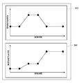
- the detection / detection probability display unit 706 displays a graph of the transition of the detection probability of the target by the search sensor device 202 when the optimum search path for each search condition parameter is selected, or the detection probability of the detection target from the target object. A graph showing the transition is displayed.
- the parameter input device 201 inputs a request level corresponding to one detection probability and a request level for the detected probability for each search condition. However, when the request level for the detection probability and the request level for the detection probability vary within the mission period (movement time), the request level (detection probability request level, detection probability request level) is set to the time as shown in FIG. You may set to update according to.
- FIG. 7 is a diagram showing fluctuations in the detection probability requirement and the detected probability requirement.
- Requirement that fluctuates with time indicates that the importance of each parameter in the mission to be implemented changes with time. For example, if detection from a threatening target is a problem immediately after the start of the mission, but the problem disappears even if it is detected after a certain time, set the detection probability request rate high in the time immediately after the start of the mission.
- the request level is set low after a certain time. In this case, as the request level (detection probability request level, detected probability request level) used in the calculation of the movement cost, a value at the arrival date and time to the position where the movement cost is calculated is used.
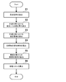
- FIG. 8 is a diagram illustrating an example of an operation for calculating a search route.
- FIG. 9 is a diagram illustrating an example of an operation for calculating a movement cost.
- FIGS. 1 to 6 are referred to as appropriate.
- the search support method is implemented by operating the search support device. Therefore, the description of the search support method in the present embodiment is replaced with the following description of the operation of the search support apparatus.
- step A1 search condition selection
- the search path calculation unit 250 selects one search condition parameter.
- step A2 route search target range calculation
- the search route calculation unit 250 calculates a range to be searched for a route.
- the speed of the vehicle 110 set by the search condition parameter is used for the movement between the start position and the end position set by the search condition parameter, it can be reached within the mission execution time set by the search condition parameter. Only the range is the route search range.
- step A3 the search route calculation unit 250 determines whether or not the vehicle 110 can reach the end position under the selected condition.
- the movement time of the vehicle 110 exceeds the mission performance time (arrival date and time) set by the mission setting information (step A3: No), it is determined that it is not reachable under the selected condition, and is not set as the target range of the subsequent route search 305.
- step A4 route search grid generation
- the search route calculation unit 250 enters the route search range.
- the grid division process is executed for the above.
- step A5 the search route calculation unit 250 executes a route search process between the start position and the end position set by the search condition parameter.
- a route search process between the start position and the end position set by the search condition parameter.
- the Dijkstra method or A * method that is a route search algorithm that can set an individual travel cost for a route is used.
- the movement cost between cells shall use the method weighted according to the search condition parameter shown in FIG.
- step A6 the search route calculation unit 250 determines whether search routes have been calculated for all search condition parameters input from the parameter input device 201. When the search route is not calculated for all search condition parameters (step A6: No), the search route calculation unit 250 executes search route calculation for the next search condition parameter. When the search route is calculated for all the search condition parameters (step A6: Yes), the search route calculation unit 250 ends the search route calculation process.
- step B1 (calculation of the arrival time of the target cell)
- the detection probability calculation unit 261 or the detected probability calculation unit 262 determines whether the vehicle from the reference cell for the movement cost to the adjacent cell for which the movement cost is calculated.
- the travel time of 110 is calculated using the current velocity information and the like.
- step B2 (calculation of the estimated target position at the target cell arrival date and time)
- the detection probability calculation unit 261 or the detected probability calculation unit 262 calculates the target cell arrival date and time from the target position information 220 and the wide area target position information 241. The distribution of the existence probability of the target at is calculated.
- step B3 (calculation of the estimated environment at the target cell arrival date and time)
- the detection probability calculation unit 261 or the detected probability calculation unit 262 corrects the wide-area underwater sound speed information 243 with the surrounding underwater sound speed information 230, thereby An estimated value of the underwater sound velocity distribution at the arrival date and time is calculated.
- the order of the process of step B2 and step B3 is not limited.
- step B4 (calculation of the detection probability of the target by the mounted sensor in the target cell)
- the detection probability calculation unit 261 includes the distribution of the probability of presence of the target at the arrival date and time of the target cell, the estimated value of the underwater sound velocity distribution, Using the search sensor capability data 255 and the terrain data 256, the detection probability of the target in the target cell is calculated. See FIG.
- step B5 (calculation of the detection probability from the target object which is a threat in the target cell)
- the detection probability calculation unit 262 calculates the underwater sound speed distribution estimated value and the threat target sensor performance information 240 at the arrival date and time of the target cell. Then, using the wide area risk information 244 and the terrain data 256, the detection probability from the target object which is a threat in the target cell is calculated. See FIG.
- the order of the process of step B4 and step B5 is not limited.
- step B6 (calculation of the weighted movement cost to the target cell)
- the movement cost calculation unit 263 is set with respect to the movement time between the cells using the detection probability of the target in the target cell and the search condition parameter.
- a multiplication value with the required degree of target detection probability is calculated.
- the movement cost calculation unit 263 multiplies the detection probability from the target object as a threat in the target cell by the request level of the detection probability from the target object as a threat set using the search condition parameter. Is calculated.
- the movement cost calculation part 263 multiplies these multiplication values, and calculates the movement cost to an object cell.
- the search effective range of the search sensor unit 2 the search effective range of the sensor held by the target object, and the distribution of the existence probability of the target object as a threat
- the search route to the object can be calculated. Therefore, for example, even when a sensor that is susceptible to the influence of the surrounding environment is mounted on the vehicle, the search route to the target position can be calculated according to the surrounding environment and the threatening object. As a result, even if the sensor mounted on the vehicle uses a sensor that is easily influenced by the surrounding environment, it is possible to calculate a search route that is highly optimal for the purpose of the mission.
- the search support device 1 may be applied to an unmanned vehicle such as an underwater drone or a water drone.
- the search support device 1 installed in the drone may store search condition parameters that have been prioritized and execute search route search processing using these search condition parameters.
- the search route with the highest priority can be selected and used for behavior determination of the drone.
- the program in the embodiment of the present invention may be a program that causes a computer to execute steps A1 to A6 shown in FIG. 8 and a program that causes steps B1 to B6 shown in FIG. 9 to be executed. Further, any program that displays display information on the display device 206 may be used. By installing and executing this program on a computer, the search support device and the search support method in the present embodiment can be realized.
- the computer processor includes a search route calculation unit 250, a sensor performance estimation unit 251, a target position estimation unit 252, an underwater sound speed estimation unit 253, a flow velocity estimation unit 254, a detection probability calculation unit 261, a detected probability calculation unit 262, a movement It functions as a cost calculation unit 263 and a display information generation unit 264 to perform processing.
- each computer has a search path calculation unit 250, a sensor performance estimation unit 251, a target position estimation unit 252, an underwater sound speed estimation unit 253, a flow velocity estimation unit 254, a detection probability calculation unit 261, and a detected probability. It may function as any one of the calculation unit 262, the movement cost calculation unit 263, and the display information generation unit 264.
- FIG. 10 is a block diagram illustrating an example of a computer that implements the search support apparatus according to the embodiment of the present invention.
- the computer 410 includes a CPU 411, a main memory 412, a storage device 413, an input interface 414, a display controller 415, a data reader / writer 416, and a communication interface 417. These units are connected to each other via a bus 421 so that data communication is possible.
- the computer 410 may include a GPU (Graphics Processing Unit) or an FPGA (Field-Programmable Gate Array) in addition to the CPU 411 or instead of the CPU 411.
- the CPU 411 performs various calculations by developing the program (code) in the present embodiment stored in the storage device 413 in the main memory 412 and executing them in a predetermined order.
- the main memory 412 is typically a volatile storage device such as a DRAM (Dynamic Random Access Memory).
- the program in this embodiment is provided in a state stored in a computer-readable recording medium 420.
- the program in the present embodiment may be distributed on the Internet connected via the communication interface 417.
- the storage device 413 include a semiconductor storage device such as a flash memory in addition to a hard disk drive.
- the input interface 414 mediates data transmission between the CPU 411 and an input device 418 such as a keyboard and a mouse.
- the display controller 415 is connected to the display device 419 and controls display on the display device 419.
- the data reader / writer 416 mediates data transmission between the CPU 411 and the recording medium 420, and reads a program from the recording medium 420 and writes a processing result in the computer 410 to the recording medium 420.
- the communication interface 417 mediates data transmission between the CPU 411 and another computer.
- the recording medium 420 include general-purpose semiconductor storage devices such as CF (Compact Flash (registered trademark)) and SD (Secure Digital), magnetic recording media such as a flexible disk, or CD- Optical recording media such as ROM (Compact Disk Read Only Memory) are listed.
- CF Compact Flash
- SD Secure Digital
- magnetic recording media such as a flexible disk
- CD- Optical recording media such as ROM (Compact Disk Read Only Memory) are listed.
- search support device 1 can also be realized by using hardware corresponding to each unit, not a computer in which a program is installed. Further, part of the search support device 1 may be realized by a program, and the remaining part may be realized by hardware.
- a search sensor for searching for a target An environmental sensor unit that measures the surrounding environment and generates environmental information based on the measurement results; Using the environment information and performance information indicating the performance of the search sensor unit, the search effective range estimation unit for estimating the search effective range of the search sensor unit, A threat effective range estimation unit that estimates the search effective range of the sensor held by the target object using the environment information and performance information indicating the performance of the sensor held by the target threat. Based on the search effective range of the search sensor unit, the search effective range of the sensor held by the object, and the distribution of the existence probability of the threat object, the search path to the target is calculated.
- Appendix 2 A search support device according to appendix 1,
- the search sensor unit generates target information having an estimated target position, existence probability distribution, moving direction, and moving speed for the target,
- the route calculation unit calculates a search route to the target based on the target information.
- a search support apparatus comprising: a detection probability calculation unit that calculates a detection probability of a target.
- a search support apparatus comprising: a detection probability calculation unit that calculates a detection probability from the target object that is a threat using performance information indicating the target environment and the estimated environment of the target position.
- a search support apparatus comprising: a movement cost calculation unit that calculates a movement cost for the estimated movement time to the target position by multiplication.
- a search support device comprising: a display information generation unit configured to generate display information for displaying the search route, the detection probability, the detection probability, or a combination thereof.
- (Appendix 7) (A) The search of the search sensor unit using the environmental information generated by measuring the surrounding environment by the environment sensor unit and based on the measurement result and the performance information indicating the performance of the search sensor unit searching for the target Estimate the effective range, (B) Using the environmental information and performance information indicating the performance of the sensor held by the threat object, the search effective range of the sensor held by the object is estimated, (C) Based on the search effective range of the search sensor unit, the search effective range of the sensor possessed by the target object, and the distribution of the probability of existence of the target object as the threat, the search path to the target object is determined.
- a search support method characterized by calculating.
- the search support method according to appendix 8, (D) Estimating the arrival date and time to reach the target position estimated using the environment information, using the target information to estimate the distribution of the existence probability of the target at the arrival date and time, The estimated environment of the target position at the arrival date and time is estimated using the estimated distribution of the existence probability of the target and the estimated environment of the target position, and the estimated target at the arrival date and time.
- a search support method comprising: calculating a detection probability of the target at a position.
- (Appendix 10) The search support method according to attachment 9, wherein (E) Estimating the arrival date and time to reach the target position estimated using the environment information, using the target information to estimate the distribution of the existence probability of the target at the arrival date and time, The estimated environment of the target position at the arrival date and time is estimated, and the distribution of the estimated existence probability of the target object and the estimated environment of the target position are used to hold the target object that is a threat
- a search support method comprising: calculating a detection probability from the target object that is a threat using performance information indicating the performance of the sensor and an environment of the estimated target position.
- Appendix 11 A search support method according to appendix 10, wherein (F) The value obtained by multiplying the estimated probability at the target position multiplied by the required degree of detection probability is multiplied by the detected probability at the estimated target position and the required degree of detected probability.
- a search support method characterized in that a movement cost is calculated with respect to the estimated movement time to the target position by multiplying by a value.
- Appendix 14 A computer-readable recording medium according to appendix 13, In the step (c), based on the target information generated by the search sensor unit, the target information including the estimated target position, the distribution of existence probability, the moving direction, and the moving speed.
- a computer-readable recording medium characterized by calculating a search route to a target.
- (Appendix 15) A computer-readable recording medium according to appendix 14, The program is stored in the computer. (D) Estimating the arrival date and time to reach the target position estimated using the environment information, using the target information to estimate the distribution of the existence probability of the target at the arrival date and time, The estimated environment of the target position at the arrival date and time is estimated using the estimated distribution of the existence probability of the target and the estimated environment of the target position, and the estimated target at the arrival date and time. Further comprising instructions for performing a step of calculating a detection probability of the target at a position; A computer-readable recording medium on which a program is recorded.
- (Appendix 16) The computer-readable recording medium according to appendix 15, The program is stored in the computer. (E) Estimating the arrival date and time to reach the target position estimated using the environment information, using the target information to estimate the distribution of the existence probability of the target at the arrival date and time, The estimated environment of the target position at the arrival date and time is estimated, and the distribution of the estimated existence probability of the target object and the estimated environment of the target position are used to hold the target object that is a threat Further including an instruction to execute a step of calculating a detection probability from the target object which is a threat using performance information indicating the performance of the sensor and the environment of the estimated target position; A computer-readable recording medium on which a program is recorded.
- Appendix 17 The computer-readable recording medium according to appendix 16, The program is stored in the computer.
- F The value obtained by multiplying the estimated probability at the target position multiplied by the required degree of detection probability is multiplied by the detected probability at the estimated target position and the required degree of detected probability.
- Appendix 18 A computer-readable recording medium according to appendix 17, The program is stored in the computer.
- G generating display information for displaying the search path, detection probability, detection probability, or a combination thereof;
- the search route to the target position can be calculated according to the surrounding environment and the threatening object.
- the present invention is useful in a field where a search route needs to be calculated.
Landscapes
- Engineering & Computer Science (AREA)
- Radar, Positioning & Navigation (AREA)
- Remote Sensing (AREA)
- Physics & Mathematics (AREA)
- General Physics & Mathematics (AREA)
- Acoustics & Sound (AREA)
- Computer Networks & Wireless Communication (AREA)
- Ocean & Marine Engineering (AREA)
- Combustion & Propulsion (AREA)
- Chemical & Material Sciences (AREA)
- General Engineering & Computer Science (AREA)
- Automation & Control Theory (AREA)
- Mechanical Engineering (AREA)
- Navigation (AREA)
- Traffic Control Systems (AREA)
Abstract
L'invention concerne un dispositif d'aide à la recherche, comprenant : une unité de capteur de recherche (2), une unité de capteur d'environnement (3), une unité d'estimation de plage efficace de recherche (4), une unité d'estimation de plage efficace de menace (5) et une unité de calcul de trajet (6). L'unité de capteur d'environnement (3) mesure un environnement ambiant et génère des informations d'environnement sur la base de résultats de mesure. L'unité d'estimation de plage efficace de recherche (4) estime une plage efficace de recherche de la section de capteur de recherche (2) à l'aide des informations d'environnement et des informations de performances indicatives des performances de l'unité de capteur de recherche. L'unité d'estimation de plage efficace de menace (5) estime une plage efficace de recherche du capteur dans un objet menaçant à l'aide des informations d'environnement et des informations de performances indicatives des performances d'un capteur dans l'objet menaçant. L'unité de calcul de trajet (6) calcule un trajet de recherche vers l'objet sur la base de la plage efficace de recherche de l'unité de capteur de recherche (2), de la plage efficace de recherche du capteur dans l'objet et d'une distribution des probabilités d'existence de l'objet menaçant.
Priority Applications (3)
| Application Number | Priority Date | Filing Date | Title |
|---|---|---|---|
| JP2020510713A JP6984739B2 (ja) | 2018-03-26 | 2019-03-18 | 捜索支援装置、捜索支援方法、及びプログラム |
| EP19777522.4A EP3779923B1 (fr) | 2018-03-26 | 2019-03-18 | Support de recherche pour calculer un itinéraire pour rechercher un objet |
| US17/041,564 US20210018319A1 (en) | 2018-03-26 | 2019-03-18 | Search support apparatus, search support method, and computer-readable recording medium |
Applications Claiming Priority (2)
| Application Number | Priority Date | Filing Date | Title |
|---|---|---|---|
| JP2018-058821 | 2018-03-26 | ||
| JP2018058821 | 2018-03-26 |
Publications (1)
| Publication Number | Publication Date |
|---|---|
| WO2019188530A1 true WO2019188530A1 (fr) | 2019-10-03 |
Family
ID=68061614
Family Applications (1)
| Application Number | Title | Priority Date | Filing Date |
|---|---|---|---|
| PCT/JP2019/011300 Ceased WO2019188530A1 (fr) | 2018-03-26 | 2019-03-18 | Dispositif et procédé de support à la recherche et support d'enregistrement lisible par ordinateur |
Country Status (4)
| Country | Link |
|---|---|
| US (1) | US20210018319A1 (fr) |
| EP (1) | EP3779923B1 (fr) |
| JP (1) | JP6984739B2 (fr) |
| WO (1) | WO2019188530A1 (fr) |
Cited By (1)
| Publication number | Priority date | Publication date | Assignee | Title |
|---|---|---|---|---|
| JP2021135473A (ja) * | 2020-02-28 | 2021-09-13 | 株式会社日立製作所 | 捜索支援システム、捜索支援方法 |
Families Citing this family (3)
| Publication number | Priority date | Publication date | Assignee | Title |
|---|---|---|---|---|
| US11397087B1 (en) * | 2019-06-27 | 2022-07-26 | Amazon Technologies, Inc. | Ocean-based storage and distribution of items |
| JP2024093256A (ja) * | 2022-12-27 | 2024-07-09 | 株式会社日立製作所 | 環境対応モデル生成装置、環境対応モデル生成システム及び環境対応モデル生成方法 |
| KR102796828B1 (ko) * | 2023-02-10 | 2025-04-16 | 국방과학연구소 | 센서의 표적 탐지 성능 확인을 위한 전자 장치 및 그의 동작 방법 |
Citations (9)
| Publication number | Priority date | Publication date | Assignee | Title |
|---|---|---|---|---|
| JPH04298000A (ja) | 1991-03-26 | 1992-10-21 | Mitsubishi Electric Corp | 飛行計画立案装置および飛行計画立案方法 |
| JP2000292528A (ja) * | 1999-04-08 | 2000-10-20 | Nec Corp | 捜索要領算出装置及び捜索要領算出方法 |
| JP2009286230A (ja) | 2008-05-28 | 2009-12-10 | Mitsui Eng & Shipbuild Co Ltd | 船舶の運航支援システムと船舶の運航支援方法 |
| US20110299734A1 (en) * | 2009-02-20 | 2011-12-08 | Eads Deutschland Gmbh | Method and system for detecting target objects |
| KR20130018120A (ko) * | 2011-08-10 | 2013-02-20 | 엘아이지넥스원 주식회사 | 기동패턴을 고려하여 위협 표적을 식별하기 위한 장치 |
| JP2013190344A (ja) * | 2012-03-14 | 2013-09-26 | Nec Corp | 水中物体捜索計画立案支援装置、水中物体捜索計画立案支援方法およびプログラム |
| JP2015001377A (ja) | 2013-06-13 | 2015-01-05 | 富士重工業株式会社 | 飛行経路探索装置及び飛行経路探索プログラム |
| JP2018046427A (ja) * | 2016-09-15 | 2018-03-22 | 株式会社Subaru | 目標捜索装置、目標捜索方法及び目標捜索プログラム |
| JP2018058821A (ja) | 2016-09-28 | 2018-04-12 | 大阪ガスケミカル株式会社 | 抗ウイルス剤 |
Family Cites Families (6)
| Publication number | Priority date | Publication date | Assignee | Title |
|---|---|---|---|---|
| US6182007B1 (en) * | 1999-03-11 | 2001-01-30 | Lockheed Martin Corp. | Incorporating aspect angle into route planners |
| US7047861B2 (en) * | 2002-04-22 | 2006-05-23 | Neal Solomon | System, methods and apparatus for managing a weapon system |
| US8244469B2 (en) * | 2008-03-16 | 2012-08-14 | Irobot Corporation | Collaborative engagement for target identification and tracking |
| US8566027B2 (en) * | 2012-03-14 | 2013-10-22 | Lockheed Martin Corporation | Route re-planning using enemy force lethality projection |
| CN102901498B (zh) * | 2012-09-21 | 2015-03-25 | 北京航空航天大学 | 一种不确定环境下的无人飞行器编队协同搜索和动态任务分配方法 |
| US9824596B2 (en) * | 2013-08-30 | 2017-11-21 | Insitu, Inc. | Unmanned vehicle searches |
-
2019
- 2019-03-18 US US17/041,564 patent/US20210018319A1/en not_active Abandoned
- 2019-03-18 WO PCT/JP2019/011300 patent/WO2019188530A1/fr not_active Ceased
- 2019-03-18 JP JP2020510713A patent/JP6984739B2/ja active Active
- 2019-03-18 EP EP19777522.4A patent/EP3779923B1/fr active Active
Patent Citations (9)
| Publication number | Priority date | Publication date | Assignee | Title |
|---|---|---|---|---|
| JPH04298000A (ja) | 1991-03-26 | 1992-10-21 | Mitsubishi Electric Corp | 飛行計画立案装置および飛行計画立案方法 |
| JP2000292528A (ja) * | 1999-04-08 | 2000-10-20 | Nec Corp | 捜索要領算出装置及び捜索要領算出方法 |
| JP2009286230A (ja) | 2008-05-28 | 2009-12-10 | Mitsui Eng & Shipbuild Co Ltd | 船舶の運航支援システムと船舶の運航支援方法 |
| US20110299734A1 (en) * | 2009-02-20 | 2011-12-08 | Eads Deutschland Gmbh | Method and system for detecting target objects |
| KR20130018120A (ko) * | 2011-08-10 | 2013-02-20 | 엘아이지넥스원 주식회사 | 기동패턴을 고려하여 위협 표적을 식별하기 위한 장치 |
| JP2013190344A (ja) * | 2012-03-14 | 2013-09-26 | Nec Corp | 水中物体捜索計画立案支援装置、水中物体捜索計画立案支援方法およびプログラム |
| JP2015001377A (ja) | 2013-06-13 | 2015-01-05 | 富士重工業株式会社 | 飛行経路探索装置及び飛行経路探索プログラム |
| JP2018046427A (ja) * | 2016-09-15 | 2018-03-22 | 株式会社Subaru | 目標捜索装置、目標捜索方法及び目標捜索プログラム |
| JP2018058821A (ja) | 2016-09-28 | 2018-04-12 | 大阪ガスケミカル株式会社 | 抗ウイルス剤 |
Cited By (2)
| Publication number | Priority date | Publication date | Assignee | Title |
|---|---|---|---|---|
| JP2021135473A (ja) * | 2020-02-28 | 2021-09-13 | 株式会社日立製作所 | 捜索支援システム、捜索支援方法 |
| JP7407018B2 (ja) | 2020-02-28 | 2023-12-28 | 株式会社日立製作所 | 捜索支援システム、捜索支援方法 |
Also Published As
| Publication number | Publication date |
|---|---|
| EP3779923A4 (fr) | 2021-05-19 |
| EP3779923B1 (fr) | 2023-10-04 |
| JPWO2019188530A1 (ja) | 2021-03-25 |
| JP6984739B2 (ja) | 2021-12-22 |
| EP3779923A1 (fr) | 2021-02-17 |
| US20210018319A1 (en) | 2021-01-21 |
Similar Documents
| Publication | Publication Date | Title |
|---|---|---|
| US10852749B2 (en) | Learning good features for visual odometry | |
| JP6984739B2 (ja) | 捜索支援装置、捜索支援方法、及びプログラム | |
| US11377119B2 (en) | Drifting correction between planning stage and controlling stage of operating autonomous driving vehicles | |
| EP3341265B1 (fr) | Procédé d'estimation de retard de système pour commande de véhicule autonome | |
| JP4866951B2 (ja) | 測位組み合わせ決定システム | |
| EP3743853A1 (fr) | Réalisation de tâches de navigation à l'aide de codes de grille | |
| JP2021530828A (ja) | 船舶を制御するシステムおよび方法 | |
| KR20250161388A (ko) | 고정된 항로에 대한 선박의 rpm 최적화 방법 및 그 장치 | |
| JP2025089485A (ja) | 情報処理装置、情報処理方法、プログラム及び記憶媒体 | |
| JP2022123401A (ja) | 経路計画装置、移動体、経路計画方法及びプログラム | |
| JP2019148456A (ja) | 算出装置、自己位置算出方法、およびプログラム | |
| EP3669247A1 (fr) | Procédé d'évaluation de système de localisation de véhicules de conduite autonome | |
| CN117195673A (zh) | 漂浮物漂移速度的预测方法、装置、设备及存储介质 | |
| JP6051742B2 (ja) | 信頼度導出装置、信頼度導出方法、信頼度導出プログラム及びナビゲーション装置 | |
| CN110442142A (zh) | 速度数据处理方法、装置、电子设备及计算机可读介质 | |
| JP2023040680A (ja) | 情報処理装置、制御方法、プログラム及び記憶媒体 | |
| JP2017090196A (ja) | 風向風速補正システム、風向風速提示システム、風向風速補正方法、風向風速提示方法及びプログラム | |
| JP5561424B1 (ja) | 表示制御装置、表示制御方法およびプログラム | |
| WO2022091677A1 (fr) | Système de surveillance d'embarcation, procédé de surveillance d'embarcation, dispositif de traitement d'informations et programme | |
| JP7625315B1 (ja) | 情報処理装置、情報処理方法、及びプログラム | |
| JP7540559B1 (ja) | 自己位置推定装置及び自己位置推定方法 | |
| EP4699921A1 (fr) | Procédé et dispositif d'optimisation du régime d'un navire pour itinéraire fixe | |
| JP2025082619A (ja) | 運航支援システム、運航支援方法及びプログラム | |
| KR20260038770A (ko) | 선박 조종 시각화 장치 및 방법을 이용하는 선박 | |
| WO2023037502A1 (fr) | Dispositif serveur, procédé de commande, programme, et support de stockage |
Legal Events
| Date | Code | Title | Description |
|---|---|---|---|
| 121 | Ep: the epo has been informed by wipo that ep was designated in this application |
Ref document number: 19777522 Country of ref document: EP Kind code of ref document: A1 |
|
| ENP | Entry into the national phase |
Ref document number: 2020510713 Country of ref document: JP Kind code of ref document: A |
|
| NENP | Non-entry into the national phase |
Ref country code: DE |
|
| ENP | Entry into the national phase |
Ref document number: 2019777522 Country of ref document: EP Effective date: 20201026 |