WO2019188633A1 - Appareil de transmission optique, système de communication optique et procédé de communication optique - Google Patents
Appareil de transmission optique, système de communication optique et procédé de communication optique Download PDFInfo
- Publication number
- WO2019188633A1 WO2019188633A1 PCT/JP2019/011627 JP2019011627W WO2019188633A1 WO 2019188633 A1 WO2019188633 A1 WO 2019188633A1 JP 2019011627 W JP2019011627 W JP 2019011627W WO 2019188633 A1 WO2019188633 A1 WO 2019188633A1
- Authority
- WO
- WIPO (PCT)
- Prior art keywords
- optical
- optical signal
- wavelength
- band
- wavelength band
- Prior art date
- Legal status (The legal status is an assumption and is not a legal conclusion. Google has not performed a legal analysis and makes no representation as to the accuracy of the status listed.)
- Ceased
Links
Images














Classifications
-
- H—ELECTRICITY
- H04—ELECTRIC COMMUNICATION TECHNIQUE
- H04B—TRANSMISSION
- H04B10/00—Transmission systems employing electromagnetic waves other than radio-waves, e.g. infrared, visible or ultraviolet light, or employing corpuscular radiation, e.g. quantum communication
- H04B10/07—Arrangements for monitoring or testing transmission systems; Arrangements for fault measurement of transmission systems
- H04B10/075—Arrangements for monitoring or testing transmission systems; Arrangements for fault measurement of transmission systems using an in-service signal
- H04B10/079—Arrangements for monitoring or testing transmission systems; Arrangements for fault measurement of transmission systems using an in-service signal using measurements of the data signal
-
- H—ELECTRICITY
- H04—ELECTRIC COMMUNICATION TECHNIQUE
- H04B—TRANSMISSION
- H04B10/00—Transmission systems employing electromagnetic waves other than radio-waves, e.g. infrared, visible or ultraviolet light, or employing corpuscular radiation, e.g. quantum communication
- H04B10/25—Arrangements specific to fibre transmission
-
- H—ELECTRICITY
- H04—ELECTRIC COMMUNICATION TECHNIQUE
- H04B—TRANSMISSION
- H04B10/00—Transmission systems employing electromagnetic waves other than radio-waves, e.g. infrared, visible or ultraviolet light, or employing corpuscular radiation, e.g. quantum communication
- H04B10/50—Transmitters
-
- H—ELECTRICITY
- H04—ELECTRIC COMMUNICATION TECHNIQUE
- H04B—TRANSMISSION
- H04B10/00—Transmission systems employing electromagnetic waves other than radio-waves, e.g. infrared, visible or ultraviolet light, or employing corpuscular radiation, e.g. quantum communication
- H04B10/50—Transmitters
- H04B10/564—Power control
-
- H—ELECTRICITY
- H04—ELECTRIC COMMUNICATION TECHNIQUE
- H04B—TRANSMISSION
- H04B10/00—Transmission systems employing electromagnetic waves other than radio-waves, e.g. infrared, visible or ultraviolet light, or employing corpuscular radiation, e.g. quantum communication
- H04B10/50—Transmitters
- H04B10/572—Wavelength control
-
- H—ELECTRICITY
- H04—ELECTRIC COMMUNICATION TECHNIQUE
- H04J—MULTIPLEX COMMUNICATION
- H04J14/00—Optical multiplex systems
- H04J14/02—Wavelength-division multiplex systems
- H04J14/03—WDM arrangements
- H04J14/0305—WDM arrangements in end terminals
-
- H—ELECTRICITY
- H04—ELECTRIC COMMUNICATION TECHNIQUE
- H04J—MULTIPLEX COMMUNICATION
- H04J14/00—Optical multiplex systems
- H04J14/02—Wavelength-division multiplex systems
- H04J14/03—WDM arrangements
- H04J14/0307—Multiplexers; Demultiplexers
Definitions
- the present invention relates to an optical transmission device, an optical submarine cable system, and an optical communication method.
- a wavelength division multiplexing (WDM) system that multiplexes and transmits optical signals of respective wavelengths is used in order to realize large-capacity communication.
- WDM wavelength division multiplexing
- a WDM signal composed of a plurality of optical signals having different wavelengths is transmitted over one optical fiber.
- WSS Wavelength Selective Switch
- the WSS can control multiplexing / demultiplexing and optical attenuation in units of wavelengths for an input WDM signal.
- Patent Document 1 discloses an optical transmission apparatus including a WSS (Wavelength Selective Switch) that multiplexes and outputs a plurality of optical signals.
- WSS Widelength Selective Switch
- Patent Document 2 discloses an optical transmission device that adjusts the attenuation amount of a subcarrier signal present at an edge portion of a super channel signal. Further, Patent Document 3 and Patent Document 4 also disclose related technologies.
- WSS has ports for inputting and outputting optical signals, and it is possible to set which wavelength band optical signals are selectively input and output on a port basis.
- the narrowing of the optical spectrum described above occurs in the wavelength band of the optical signal input / output by each port of the WSS. Therefore, in order to further improve the signal quality, it is conceivable to control the optical signal in consideration of the wavelength band input / output by each port of the WSS, but the above-mentioned prior art does not disclose the method. .
- An optical transmission device includes a transmitter that outputs an optical signal, and a multiplexing device that outputs a wavelength-multiplexed optical signal including an optical signal input from the transmitter, and the multiplexing device includes the transmission An input port set to transmit the first wavelength band of the optical signal input from the optical device, and the optical attenuation amount can be adjusted in a predetermined wavelength band unit, and the first of the optical signal transmitted through the input port An intensity adjustment unit for adjusting the optical attenuation amount of the edge band of the wavelength band to be smaller than the optical attenuation amount of the central band of the first wavelength band, and a wavelength multiplexed optical signal including the optical signal of which the optical attenuation value is adjusted And an output port.
- An optical transmission system includes a first optical transmission device that outputs a wavelength-multiplexed optical signal and a second optical transmission device that outputs a wavelength-multiplexed optical signal, and the first optical transmission device includes: A transmitter that outputs an optical signal; and a multiplexing device that outputs a wavelength-multiplexed optical signal including an optical signal input from the transmitter, wherein the multiplexing device includes a first optical signal input from the transmitter.
- An input port that is set to transmit one wavelength band, and an optical attenuation amount that can be adjusted in units of a predetermined wavelength band, and light in an edge band of the first wavelength band of an optical signal that passes through the input port
- An intensity adjustment unit that adjusts an attenuation amount to be smaller than an optical attenuation amount in a central band of the first wavelength band
- an output port that outputs a wavelength multiplexed optical signal including the optical signal in which the optical attenuation amount is adjusted. It is characterized by.
- the optical transmission method transmits a first wavelength band of an input optical signal, and determines the optical attenuation amount of the edge band of the first wavelength band for the transmitted optical signal at the center of the first wavelength band.
- a wavelength-multiplexed optical signal including an optical signal that is adjusted to be smaller than the optical attenuation amount in the band and includes the optical attenuation amount is output.
- an optical transmission device an optical communication system, and an optical communication method that adjust the optical signal intensity so as to suppress the narrowing of the optical spectrum caused by passing through the WSS.
- FIG. 1 is a diagram illustrating a configuration example of an optical submarine cable system according to a first embodiment.
- FIG. 1 is a diagram illustrating a configuration example of an optical transmission apparatus according to a first embodiment. It is a figure which shows the structural example of the multiplexing apparatus which concerns on 1st Embodiment. It is a figure explaining adjustment of the amount of light attenuation concerning a 1st embodiment. It is a figure explaining adjustment of the amount of light attenuation concerning a 1st embodiment. It is a figure explaining adjustment of the amount of light attenuation concerning a 1st embodiment. It is a figure explaining adjustment of the amount of light attenuation concerning a 1st embodiment. It is a figure explaining adjustment of the amount of light attenuation concerning a 1st embodiment. It is a figure explaining adjustment of the amount of light attenuation concerning a 1st embodiment.
- FIG. 1 is a diagram illustrating an example of an optical submarine cable system according to a first embodiment of the present invention.
- the optical submarine cable system 1000 of FIG. 1 includes a terminal station 1, a terminal station 2, a terminal station 3, an optical transmission line 4, and a submarine branching device 5.
- the terminal station 1, the terminal station 2, the terminal station 3, and the submarine branching device 5 are connected to each other via an optical transmission line 4.
- the terminal stations 1, 2 and 3 transmit WDM signals via the optical transmission path 4.
- the submarine branching device 5 has a function of branching and outputting a WDM signal input from each terminal station in wavelength units.
- the configuration of the optical submarine cable system is not limited to FIG.
- a configuration in which the terminal station 3 and the submarine branching device 5 are not provided and the terminal station 1 and the terminal station 2 are connected via an optical submarine cable is also conceivable.
- the optical transmission line 4 may be provided with an optical amplifier that amplifies an optical signal to be transmitted.
- Terminal stations 1, 2, and 3 are station buildings installed on land, and have an optical transmission device capable of transmitting optical signals therein.
- FIG. 2 is a diagram illustrating a configuration example of an optical transmission apparatus.
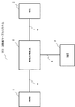
- the optical transmission device 10 illustrated in FIG. 2 includes a transmitter 101 and a multiplexing device 102.
- the transmitter 101 has a function of outputting an optical signal having a predetermined wavelength.
- the transmitter 101 may be constituted by a transponder, for example. Further, the wavelength of the optical signal transmitted by the transmitter 101 may be changeable. 2 shows three transmitters 101-1, 101-2, and 101-3, the number of transmitters 101 is not limited to this.
- the multiplexer 102 outputs the optical signal input from the transmitter 101 as a wavelength multiplexed optical signal.
- FIG. 3 is a diagram illustrating a configuration example of the multiplexing device 102.
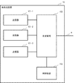
- the multiplexing device 102 includes an input port 1021, an intensity adjustment unit 1022, and an output port 1023. Note that the multiplexer 102 is configured by, for example, WSS.
- FIG. 3 shows the minimum configuration of the multiplexing device 102.
- the multiplexing device 102 includes at least as many input ports 1021 as the number of the plurality of transmitters 101. For example, as shown in FIG. 2, when the optical transmission device 10 includes three transmitters 101-1, 101-2, and 101-3, the multiplexing device 102 includes at least three input ports 1021.
- the input port 1021 is connected to one of the transmitters 101, and an optical signal is input from the transmitter 101.
- the input port 1021 is set to transmit a predetermined wavelength band in the optical signal input from the transmitter 101.
- the predetermined wavelength band transmitted through the input port 1021 can be arbitrarily changed. For example, it can be changed by setting from an external control device (not shown).
- the intensity adjustment unit 1022 can adjust the amount of light attenuation in units of a predetermined wavelength band.
- this predetermined wavelength band unit is referred to as a minimum resolution band.
- the minimum resolution band is, for example, 3.125 GHz or 6.25 GHz.
- the intensity adjustment unit 1022 may be realized by one or a plurality of variable optical attenuators.
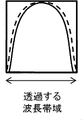
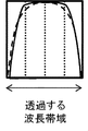
- FIG. 4A to FIG. 4E are diagrams showing optical signal spectra and the amount of light attenuation by the intensity adjustment unit 1022.
- FIG. 4A is a diagram illustrating an optical spectrum before the optical signal output from the point (a) in FIG. 3, that is, one of the transmitters 101 is input to the multiplexing device 102.
- the optical signal output from the transmitter 101 has a channel having a wavelength bandwidth indicated on the horizontal axis of FIG. 4A.
- the wavelength band shown on the horizontal axis of FIG. 4B is set as the wavelength band to be transmitted to the input port 1021.
- the wavelength band set for the input port 1021 corresponds to the wavelength band of the input optical signal.
- the wavelength band set in the input port 1021 is a wavelength band equal to the wavelength band of the input optical signal or a wavelength band including the wavelength band of the input optical signal.
- the optical attenuation can be set to zero.
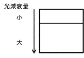
- the intensity adjustment unit 1022 adjusts the amount of light attenuation as shown in FIG. 4E.
- the intensity adjuster sets the light attenuation to a different value for each minimum resolution band.
- the grid width shown in FIG. 4E indicates the minimum resolution band.
- a wavelength band positioned at both ends (edges) of the wavelength band set for the input port 1021 is referred to as an edge band, and a wavelength band positioned inside the edge band is referred to as a central band.
- the wavelength band set for the input port 1021 is divided by the minimum resolution band, and the edge band is the minimum resolution band located closest to the edge.
- the intensity adjustment unit 1022 adjusts the light attenuation amount in the edge band to be smaller than the light attenuation amount in the center band. As a result, as shown in FIG. 4C, it is possible to suppress the narrowing of the optical spectrum that occurs in the wavelength band set in the wavelength selection unit.
- the wavelength band transmitted through the input port 1021 is illustrated as being configured with four minimum resolution bands, but the wavelength band transmitted through the input port 1021 and the minimum resolution band are illustrated.
- the relationship is not limited to this.
- the wavelength band transmitted through the input port 1021 may be configured from six minimum resolution bands.
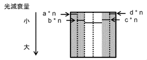
- FIG. 5B it is also possible to adjust the attenuation amounts to be different from each other in the edge bands at both ends.
- the edge band is not limited to one minimum resolution band, and a plurality of minimum resolution bands can be adjusted from the edge. At this time, it is also possible to adjust stepwise so that the amount of light attenuation decreases toward the edge.
- the multiplexing device 102 may include a plurality of input ports 1021.
- FIG. 6 is a diagram illustrating a configuration example of a multiplexing device including a plurality of input ports.
- the input port 1021-1 is connected to the transmitter 101-1
- the input port 1021-2 is connected to the transmitter 101-2
- the input port 1021-3 is connected to the transmitter 101-3.
- Each input port 1021 is set with a transmitted wavelength band.
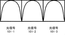
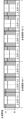
- FIG. 7A and FIG. 7B are diagrams for explaining a case where the optical attenuation is adjusted for each of the plurality of input ports. As shown in FIGS. 7A and 7B, the intensity adjustment unit 1022 performs the above-described adjustment of the optical attenuation for the wavelength band set for each input port.
- the output port 1023 outputs the intensity-adjusted optical signal to the optical transmission line 4.
- the optical device has a function of combining the plurality of optical signals and outputting them as wavelength multiplexed optical signals.
- the optical attenuation amount in the edge band is adjusted to be smaller than the optical attenuation amount in the central band in the wavelength band set at the input port of the multiplexing device. This makes it possible to compensate for the light intensity at both ends of the optical spectrum, and to suppress the narrowing of the optical spectrum that occurs in the wavelength band transmitted by the input port.
- FIG. 8 is a diagram illustrating a configuration example of the optical transmission device 10 according to the second embodiment.
- the optical transmission device 10 in FIG. 9 includes a control device 103 as compared with the optical transmission device 10 in FIG.
- the control device 103 can control the multiplexing device 102.
- the control of the multiplexing device 102 by the control device 103 will be described with reference to FIG.
- the control device 103 identifies the wavelength band set for the input port 1021.
- the control device 103 may specify a wavelength band set for the input port 1021 by referring to a control unit (not shown) included in the multiplexing device 102.
- the control device 103 may have a function of setting a wavelength band that is transmitted to the input port 1021.
- the control apparatus 103 can hold setting information for the input port 1021 and can specify the wavelength band set for the input port 1021 with reference to the setting information held.
- control device 103 may specify the input port 1021 set in a predetermined wavelength grid unit.
- the predetermined wavelength grid unit is, for example, a wavelength grid equal to the minimum resolution band.
- the control device 103 identifies each input port 1021 by identifying a wavelength grid set to an input port 1021 having a different adjacent wavelength grid as an edge.
- the wavelength band set in the above may be specified.
- the control device 103 instructs the intensity adjustment unit 1022 on the amount of light attenuation. Specifically, the optical attenuation amount is instructed for each of the edge band and the central band in the wavelength band set for the input port 1021.
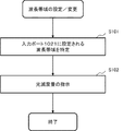
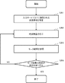
- control device 103 identifies the wavelength band set for the input port 1021 (S101).
- control device 103 instructs the light attenuation amount for each of the edge band and the central band in the specified wavelength band (S102).
- control device 103 may have a function of setting a wavelength band in the input port 1021 as described above.
- the above-described control may be started in response to the control device 103 setting a wavelength band for the input port 1021 or changing the setting.
- the optical attenuation of the edge band is adjusted to be smaller than the optical attenuation of the central band in the wavelength band set to the input port of the multiplexing device. This makes it possible to compensate for the light intensity at both ends of the optical spectrum, and to suppress the narrowing of the optical spectrum that occurs in the wavelength band transmitted by the input port.
- FIG. 12 is a diagram illustrating a configuration example of an optical transmission apparatus according to the third embodiment.
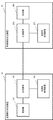
- the transmission-side optical transmission device 10 and the reception-side optical transmission device 20 include control devices 103 and 203, respectively.
- the transmission side optical transmission apparatus 10 is provided, for example, inside the terminal station 1 shown in FIG. 1, and the reception side optical transmission apparatus 20 is provided inside the opposite terminal station 2.
- the transmission-side control device 103 instructs the optical multiplexer 102 on the amount of optical attenuation based on the monitoring result of the signal quality of the optical signal. Specifically, the transmission side control device 103 monitors the BER and Q value indicating the signal quality of the optical signal.
- the transmission-side control apparatus 103 may receive a signal quality monitoring result from the reception-side control apparatus 203. Communication between the transmission side control device 103 and the reception side control device 203 may be performed via the optical transmission path 4 or may be performed via an external network.
- the control operation by the transmission-side control apparatus 103 will be described with reference to FIG. Compared to the control example described with reference to FIG. 10, the control is based on the signal quality monitoring result.
- the transmission-side control device 103 refers to the signal quality monitor result of the optical signal whose light attenuation is adjusted (S203).
- the transmission-side control apparatus 103 determines whether the signal quality monitor result satisfies a predetermined condition (S204). If the predetermined condition is satisfied (YES in S204), the control is terminated. When the predetermined condition is not satisfied (NO in S204), the process returns to S202 again to instruct the light attenuation amount.
- the predetermined condition may be that a BER (Bit Error Rate) indicating signal quality or a Q value (Quality Factor) satisfies a predetermined threshold.
- the signal quality after adjusting the light attenuation may not be improved more than the signal quality before adjusting. In this case, the light attenuation amount set before adjusting the light attenuation amount is determined as the optimum light attenuation amount.
- the light attenuation amount instructed when returning to S202 again is a light attenuation amount different from the light attenuation amount already instructed.
- the different light attenuation amount may be a value obtained by changing the light attenuation amount already instructed in a direction satisfying a predetermined condition.
- the transmission side control device 103 may control the light attenuation amount by recording a signal quality monitor result corresponding to the light attenuation amount.
- the control operation by the transmission side control device 103 will be described with reference to FIG. Compared to FIG. 13, the transmission-side control apparatus 103 performs the operations of S205-207 instead of S203 and S204.
- the transmission-side control device 103 records the signal quality monitor result as a result of adjusting the optical attenuation (S205).
- the transmission-side control device 103 determines whether or not to end the monitoring result recording (S206). If not finished (NO in S206), the process returns to S202 again.
- the transmission-side control apparatus 103 may perform control so as to adjust in units of a predetermined attenuation amount as an instruction of the optical attenuation amount performed in S202. Therefore, by repeating S202, it is possible to record the signal quality when the optical attenuation is adjusted in a predetermined attenuation unit.
- the predetermined attenuation unit may be a variable minimum amount of light attenuation that the intensity adjustment unit 1022 has, or an integer multiple thereof.
- the transmission-side control device 103 specifies an optimum light attenuation amount (S207).
- the transmission-side control apparatus 103 may specify the optical attenuation amount when the highest value is recorded among the recorded signal qualities as the optimal optical attenuation amount.
- the optical attenuation amount in the edge band is adjusted to be smaller than the optical attenuation amount in the central band in the wavelength band set at the input port of the multiplexing device. This makes it possible to compensate for the light intensity at both ends of the optical spectrum, and to suppress the narrowing of the optical spectrum that occurs in the wavelength band transmitted by the input port. Further, the optical transmission apparatus according to the third embodiment of the present invention can adjust the optical attenuation so as to further improve the signal quality by the control apparatus controlling the multiplexing apparatus based on the signal quality monitoring result. Become.
- the optical transmission apparatus performs the adjustment of the optical attenuation described in the above-described embodiments based on the reverse characteristic of the transmission characteristic of the multiplexing apparatus.
- the configuration example of the optical transmission apparatus is the same as the configuration described in the above embodiment.
- 15A to 15E are diagrams for explaining the adjustment of the optical attenuation based on the reverse characteristic of the transmission characteristic of the multiplexer 102, which is performed by the intensity adjusting unit 1022.
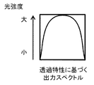
- FIG. 15A shows an output spectrum of an optical signal based on the transmission characteristics of the multiplexing device 102.
- the output spectrum is derived from the wavelength band set in the input port 1021 and the transmission characteristics of the multiplexer.
- FIG. 15B shows the inverse characteristic derived from the output spectrum shown in FIG. 15A
- FIG. 15D is a diagram showing the amount of light attenuation based on the inverse characteristic.
- the intensity adjustment unit 1022 sets a value obtained by multiplying the edge band light attenuation reduction amount derived from the inverse characteristics by a variable as the edge band light attenuation.
- a plurality of minimum resolution bands may be set as edge bands and may be adjusted for light attenuation.
- FIG. 16 is a flowchart for explaining the operation in which the control device 103 adjusts the light attenuation based on the reverse characteristic.
- the control device 103 identifies the wavelength band set for the input port 1021 (S301).
- the control device 103 determines the amount of light attenuation based on the identified wavelength band and the reverse characteristic of the transmission characteristic of the multiplexing device 102 (S302). Note that the control device 103 may be able to hold information on the transmission characteristics of the multiplexing device 102, and in this case, the light attenuation amount shown in FIG. 15D can be determined based on the held information. Become.
- the light attenuation amount in the edge band is adjusted to be smaller than the light attenuation amount in the center band in the wavelength band set at the input port of the multiplexer. This makes it possible to compensate for the light intensity at both ends of the optical spectrum, and to suppress the narrowing of the optical spectrum that occurs in the wavelength band transmitted by the input port.
- the optical transmission apparatus according to the fourth embodiment of the present invention determines the optical attenuation to be adjusted even when the reception characteristic cannot be monitored by performing control based on the reverse characteristic of the transmission characteristic of the multiplexing apparatus. It becomes possible to do.
- the optical transmission apparatus can control the amount of optical attenuation even when a plurality of multiplexing apparatuses are provided in multiple stages.
- FIG. 17 is a diagram illustrating a configuration example of an optical transmission apparatus according to the fifth embodiment.
- the optical transmission device 10 is different from the above-described embodiment in that it includes a plurality of multiplexing devices 102.
- Multiplexers 102-1 and 102-2 are connected to a plurality of transmitters 101, respectively. Similarly to the above-described embodiment, the multiplexing devices 102-1 and 102-2 output wavelength-multiplexed optical signals including the optical signal input from the transmitter 101. Note that the number of transmitters connected to the multiplexing devices 102-1 and 102-2 is not limited to the number shown in FIG.
- the multiplexing device 102-3 multiplexes and outputs the wavelength multiplexed optical signals input from the multiplexing devices 102-1 and 102-2. Since the configuration of the multiplexing device 102-3 is the same as that of the multiplexing device 102 described in the above-described embodiment, the description thereof is omitted.
- the control device 103 is configured to be able to control a plurality of multiplexing devices 102.
- the control described in the above embodiment can be applied to the control of the light attenuation amount to each multiplexing device 102 by the control device 103.
- FIG. 18A, FIG. 18B, and FIG. 18C are diagrams showing adjustment of the optical attenuation amount in each multiplexing device. According to FIG. 18A, FIG. 18B, and FIG. 18C, control is performed so that the optical attenuation amount in the edge band is smaller than the optical attenuation amount in the central band with respect to the wavelength band set in the input port included in each multiplexing device. . Note that the wavelength bands set for the input ports of the multiplexing devices 102-1 and 102-2 are different from each other.
- the adjustment of the light attenuation is not limited to that shown in FIGS. 18A, 18B, and 18C.
- the optical attenuation amount may be adjusted by the multiplexing devices 102-1 and 102-2 for the minimum resolution band corresponding to the edge band set at the input port of the multiplexing device 102-3. At this time, it is not necessary to adjust the amount of light attenuation in the multiplexer 102-3.
- the optical attenuation amount may be adjusted by the multiplexing device 102-3 for the minimum resolution band corresponding to the edge band in the wavelength band set for each input port of the multiplexing devices 102-1 and 102-2. Good.
- the light attenuation amount in the edge band is adjusted to be smaller than the light attenuation amount in the center band in the wavelength band set at the input port of the multiplexer. This makes it possible to compensate for the light intensity at both ends of the optical spectrum, and to suppress the narrowing of the optical spectrum that occurs in the wavelength band transmitted by the input port.
- the optical transmission device according to the fifth embodiment of the present invention is capable of adjusting the optical attenuation even when a plurality of multiplexing devices are provided and provided in multiple stages.
- FIG. 19 shows a configuration example of the receiving side optical transmission apparatus.
- the demultiplexing device 202 demultiplexes the wavelength multiplexed optical signal input from the optical transmission line 4 and outputs the optical signal to the receiver 201.
- FIG. 20 shows a configuration example of the demultiplexing device 202.
- the output port 2021 has the same function as the input port 1021 in FIG.
- the output port 2021 is connected to one of the receivers 201.
- the output port 2021 is set to transmit a predetermined wavelength band for the optical signal output to the receiver 201.
- FIG. 20 shows the minimum configuration of the demultiplexing device 202.
- the demultiplexing device 202 includes at least as many output ports 2021 as the number of the plurality of receivers 101. For example, as shown in FIG. 19, when the optical transmission device 20 includes three receivers 201-1, 201-2, and 201-3, the demultiplexing device 202 includes at least three output ports 2021.
- the strength adjusting unit 2022 has the same function as the strength adjusting unit 1022 of FIG.
- the input port 2023 has the same function as the output port 1023 in FIG.
- the input port 2023 outputs the wavelength multiplexed optical signal input from the optical transmission line 4 to the intensity adjustment unit 2022. *
- the light attenuation amount in the edge band is adjusted to be smaller than the light attenuation amount in the center band in the wavelength band set at the output port of the demultiplexing device. This makes it possible to compensate for the light intensity at both ends of the optical spectrum, and to suppress the narrowing of the optical spectrum that occurs in the wavelength band transmitted by the output port.
Landscapes
- Engineering & Computer Science (AREA)
- Computer Networks & Wireless Communication (AREA)
- Signal Processing (AREA)
- Physics & Mathematics (AREA)
- Electromagnetism (AREA)
- Optical Communication System (AREA)
Abstract
Le problème décrit par la présente invention est de fournir un WSS comprenant des ports à travers lesquels un signal optique est entré/sorti, et permettant de régler la bande de longueur d'onde du signal optique de façon à ce qu'elle soit sélectivement entrée/sortie pour chaque port. Dans le cas présent, le rétrécissement du spectre optique se produit dans la bande de longueur d'onde du signal optique entré/sorti en direction/en provenance de chaque port du WSS, ce qui conduit à une détérioration de la qualité du signal. La solution de l'invention porte sur un appareil de transmission optique comprenant un moyen de transmission permettant d'émettre un signal optique, et un dispositif de multiplexage permettant d'émettre en sortie un signal optique multiplexé en longueur d'onde comprenant le signal optique entré à partir du moyen de transmission, le dispositif de multiplexage comprenant un port d'entrée réglé de façon à transmettre une première bande de longueur d'onde du signal optique entré à partir du moyen de transmission, une unité de réglage d'intensité permettant de régler une quantité d'atténuation optique pour chaque bande de longueur d'onde prédéterminée, et de régler la quantité d'atténuation optique d'une bande de bord de la première bande de longueur d'onde du signal optique transmis à travers l'orifice d'entrée de façon à ce qu'elle soit inférieure à la quantité d'atténuation optique d'une bande centrale de la première bande de longueur d'onde, et un port de sortie qui émet en sortie un signal optique multiplexé en longueur d'onde comprenant le signal optique avec la quantité d'atténuation optique réglée.
Priority Applications (4)
| Application Number | Priority Date | Filing Date | Title |
|---|---|---|---|
| JP2020510766A JP7060085B2 (ja) | 2018-03-27 | 2019-03-20 | 光伝送装置、光通信システム及び光通信方法 |
| US16/967,164 US11153024B2 (en) | 2018-03-27 | 2019-03-20 | Optical transmission apparatus, optical communication system and optical communication method |
| CN201980017552.4A CN111837347B (zh) | 2018-03-27 | 2019-03-20 | 光传输设备、光通信系统和光通信方法 |
| EP19778140.4A EP3780427A4 (fr) | 2018-03-27 | 2019-03-20 | Appareil de transmission optique, système de communication optique et procédé de communication optique |
Applications Claiming Priority (2)
| Application Number | Priority Date | Filing Date | Title |
|---|---|---|---|
| JP2018060464 | 2018-03-27 | ||
| JP2018-060464 | 2018-03-27 |
Publications (1)
| Publication Number | Publication Date |
|---|---|
| WO2019188633A1 true WO2019188633A1 (fr) | 2019-10-03 |
Family
ID=68058373
Family Applications (1)
| Application Number | Title | Priority Date | Filing Date |
|---|---|---|---|
| PCT/JP2019/011627 Ceased WO2019188633A1 (fr) | 2018-03-27 | 2019-03-20 | Appareil de transmission optique, système de communication optique et procédé de communication optique |
Country Status (5)
| Country | Link |
|---|---|
| US (1) | US11153024B2 (fr) |
| EP (1) | EP3780427A4 (fr) |
| JP (1) | JP7060085B2 (fr) |
| CN (1) | CN111837347B (fr) |
| WO (1) | WO2019188633A1 (fr) |
Families Citing this family (1)
| Publication number | Priority date | Publication date | Assignee | Title |
|---|---|---|---|---|
| US11626925B2 (en) * | 2019-03-25 | 2023-04-11 | Nec Corporation | Optical transfer system, optical transmitter, and optical communication method |
Citations (7)
| Publication number | Priority date | Publication date | Assignee | Title |
|---|---|---|---|---|
| JP2011160162A (ja) | 2010-01-29 | 2011-08-18 | Fujitsu Ltd | 光ネットワークおよびその制御方法 |
| WO2012051260A1 (fr) | 2010-10-12 | 2012-04-19 | Tyco Electronics Subsea Communications Llc | Dispositif d'agrégation et de désagrégation de bande à commutation sélective de longueur d'onde, et systèmes et procédés l'utilisant |
| JP2013045079A (ja) * | 2011-08-26 | 2013-03-04 | Nippon Telegr & Teleph Corp <Ntt> | 光透過特性補正フィルタ及び光伝送システム |
| JP2013106328A (ja) | 2011-11-16 | 2013-05-30 | Fujitsu Ltd | 光伝送システム、光伝送装置、信号調整プログラム及び信号調整方法 |
| US20130142516A1 (en) * | 2011-12-02 | 2013-06-06 | At&T Intellectual Property I, L.P. | Apparatus and method for distributed compensation of narrow optical filtering effects in an optical network |
| JP2016220204A (ja) | 2015-05-18 | 2016-12-22 | 富士通株式会社 | スーパーチャネルパワープリエンファシスのための方法及びシステム |
| JP2018060464A (ja) | 2016-10-07 | 2018-04-12 | 富士通株式会社 | 家系図作成支援プログラム、家系図作成支援方法、及び家系図作成支援装置 |
Family Cites Families (9)
| Publication number | Priority date | Publication date | Assignee | Title |
|---|---|---|---|---|
| JP2000004213A (ja) * | 1998-06-12 | 2000-01-07 | Nec Corp | 波長分割多重信号光におけるoadm |
| JP3779502B2 (ja) * | 1999-08-12 | 2006-05-31 | 富士通株式会社 | 光増幅装置、光送信装置、光伝送システム、光増幅方法および光入射方法 |
| JP4792365B2 (ja) * | 2006-09-29 | 2011-10-12 | 富士通株式会社 | 光伝送装置およびその制御方法 |
| JP4941349B2 (ja) * | 2008-02-19 | 2012-05-30 | 富士通株式会社 | Ponシステムに用いる光伝送装置 |
| JP2010139854A (ja) * | 2008-12-12 | 2010-06-24 | Fujitsu Ltd | 波長多重伝送装置及び波長多重伝送方法 |
| JP5871056B2 (ja) * | 2012-03-19 | 2016-03-01 | 富士通株式会社 | 波長選択スイッチ、可変分散補償器、監視装置、監視方法、光伝送装置及び光伝送システム |
| JP6395219B2 (ja) * | 2015-01-27 | 2018-09-26 | 日本電気株式会社 | ネットワークシステム |
| JP6578962B2 (ja) * | 2016-01-25 | 2019-09-25 | 富士通株式会社 | 光伝送装置、光伝送システム、及び光信号の出力制御方法 |
| JP7147368B2 (ja) * | 2018-08-23 | 2022-10-05 | 富士通株式会社 | 伝送装置、伝送システム、及び伝送方法 |
-
2019
- 2019-03-20 JP JP2020510766A patent/JP7060085B2/ja active Active
- 2019-03-20 US US16/967,164 patent/US11153024B2/en active Active
- 2019-03-20 WO PCT/JP2019/011627 patent/WO2019188633A1/fr not_active Ceased
- 2019-03-20 CN CN201980017552.4A patent/CN111837347B/zh active Active
- 2019-03-20 EP EP19778140.4A patent/EP3780427A4/fr active Pending
Patent Citations (7)
| Publication number | Priority date | Publication date | Assignee | Title |
|---|---|---|---|---|
| JP2011160162A (ja) | 2010-01-29 | 2011-08-18 | Fujitsu Ltd | 光ネットワークおよびその制御方法 |
| WO2012051260A1 (fr) | 2010-10-12 | 2012-04-19 | Tyco Electronics Subsea Communications Llc | Dispositif d'agrégation et de désagrégation de bande à commutation sélective de longueur d'onde, et systèmes et procédés l'utilisant |
| JP2013045079A (ja) * | 2011-08-26 | 2013-03-04 | Nippon Telegr & Teleph Corp <Ntt> | 光透過特性補正フィルタ及び光伝送システム |
| JP2013106328A (ja) | 2011-11-16 | 2013-05-30 | Fujitsu Ltd | 光伝送システム、光伝送装置、信号調整プログラム及び信号調整方法 |
| US20130142516A1 (en) * | 2011-12-02 | 2013-06-06 | At&T Intellectual Property I, L.P. | Apparatus and method for distributed compensation of narrow optical filtering effects in an optical network |
| JP2016220204A (ja) | 2015-05-18 | 2016-12-22 | 富士通株式会社 | スーパーチャネルパワープリエンファシスのための方法及びシステム |
| JP2018060464A (ja) | 2016-10-07 | 2018-04-12 | 富士通株式会社 | 家系図作成支援プログラム、家系図作成支援方法、及び家系図作成支援装置 |
Non-Patent Citations (1)
| Title |
|---|
| See also references of EP3780427A4 |
Also Published As
| Publication number | Publication date |
|---|---|
| JP7060085B2 (ja) | 2022-04-26 |
| US11153024B2 (en) | 2021-10-19 |
| CN111837347A (zh) | 2020-10-27 |
| JPWO2019188633A1 (ja) | 2021-01-07 |
| CN111837347B (zh) | 2022-11-15 |
| EP3780427A1 (fr) | 2021-02-17 |
| EP3780427A4 (fr) | 2021-05-19 |
| US20210036797A1 (en) | 2021-02-04 |
Similar Documents
| Publication | Publication Date | Title |
|---|---|---|
| US8818191B2 (en) | Wavelength reallocation method and node device | |
| WO2019179320A1 (fr) | Procédé et système de commande de remplacement de canal et d'occupation spectrale | |
| EP2448153B1 (fr) | Dispositif et système de transmission optique | |
| JP7036130B2 (ja) | 光伝送装置、伝送システム、及び伝送システムの制御方法 | |
| EP3605879B1 (fr) | Système de transmission optique | |
| JP2013522995A (ja) | 光通信ネットワークの容量を最適化するための方法 | |
| JPH08256128A (ja) | 光波長多重通信装置 | |
| EP1608097A2 (fr) | Multiplexeur optique à insertion/extraction possédant une configuration de canaux à bandes | |
| JP2010139854A (ja) | 波長多重伝送装置及び波長多重伝送方法 | |
| US7519296B2 (en) | Optical demultiplexing method and optical multiplexing method, and optical transmission apparatus using same | |
| JP2016220128A (ja) | 光伝送装置 | |
| WO2019065383A1 (fr) | Unité de dérivation sous-marine, système de câble sous-marin optique, procédé de communication optique | |
| EP3166243A1 (fr) | Procédé et appareil pour fournir une protection de trajet dans un réseau de transmission optique | |
| JP2017135455A (ja) | 光伝送装置、光伝送システム、及び光信号の出力制御方法 | |
| US9577781B2 (en) | Optical transmission apparatus and optical transmission control method | |
| US9124382B2 (en) | Transmission device, transmission system, and method for adjusting passband | |
| US11115146B2 (en) | Optical signal demultiplexing device, optical signal reception device, and optical signal demultiplexing method | |
| JP7060085B2 (ja) | 光伝送装置、光通信システム及び光通信方法 | |
| JPWO2020158190A1 (ja) | 光伝送装置、端局装置、光通信システム及び光通信方法 | |
| EP1608098A1 (fr) | Multipléxeur optique à insertion-extraction avec une configuration de canal alternée | |
| US20240396659A1 (en) | A broadcast-and-select node | |
| JP7176567B2 (ja) | 光伝送装置、光通信システム及び光信号の伝送方法 | |
| EP2552037B1 (fr) | Équipement de synchronisation et procédé associé | |
| WO2022201699A1 (fr) | Dispositif de gestion de réseau, dispositif de communication, procédé de gestion de réseau et système de gestion de réseau | |
| Chavez et al. | Study of WDM channel allocation on C and L bands in high-bitrate demand scenarios |
Legal Events
| Date | Code | Title | Description |
|---|---|---|---|
| 121 | Ep: the epo has been informed by wipo that ep was designated in this application |
Ref document number: 19778140 Country of ref document: EP Kind code of ref document: A1 |
|
| ENP | Entry into the national phase |
Ref document number: 2020510766 Country of ref document: JP Kind code of ref document: A |
|
| NENP | Non-entry into the national phase |
Ref country code: DE |
|
| ENP | Entry into the national phase |
Ref document number: 2019778140 Country of ref document: EP Effective date: 20201027 |