WO2019188734A1 - 内燃機関用回転電機およびそのロータ - Google Patents
内燃機関用回転電機およびそのロータ Download PDFInfo
- Publication number
- WO2019188734A1 WO2019188734A1 PCT/JP2019/011942 JP2019011942W WO2019188734A1 WO 2019188734 A1 WO2019188734 A1 WO 2019188734A1 JP 2019011942 W JP2019011942 W JP 2019011942W WO 2019188734 A1 WO2019188734 A1 WO 2019188734A1
- Authority
- WO
- WIPO (PCT)
- Prior art keywords
- rotor
- region
- electrical machine
- internal combustion
- combustion engine
- Prior art date
- Legal status (The legal status is an assumption and is not a legal conclusion. Google has not performed a legal analysis and makes no representation as to the accuracy of the status listed.)
- Ceased
Links
Images

Classifications
-
- H—ELECTRICITY
- H02—GENERATION; CONVERSION OR DISTRIBUTION OF ELECTRIC POWER
- H02K—DYNAMO-ELECTRIC MACHINES
- H02K1/00—Details of the magnetic circuit
- H02K1/06—Details of the magnetic circuit characterised by the shape, form or construction
- H02K1/22—Rotating parts of the magnetic circuit
- H02K1/27—Rotor cores with permanent magnets
- H02K1/2786—Outer rotors
- H02K1/2787—Outer rotors the magnetisation axis of the magnets being perpendicular to the rotor axis
- H02K1/2789—Outer rotors the magnetisation axis of the magnets being perpendicular to the rotor axis the rotor consisting of two or more circumferentially positioned magnets
- H02K1/2791—Surface mounted magnets; Inset magnets
-
- F—MECHANICAL ENGINEERING; LIGHTING; HEATING; WEAPONS; BLASTING
- F02—COMBUSTION ENGINES; HOT-GAS OR COMBUSTION-PRODUCT ENGINE PLANTS
- F02N—STARTING OF COMBUSTION ENGINES; STARTING AIDS FOR SUCH ENGINES, NOT OTHERWISE PROVIDED FOR
- F02N11/00—Starting of engines by means of electric motors
- F02N11/04—Starting of engines by means of electric motors the motors being associated with current generators
-
- H—ELECTRICITY
- H02—GENERATION; CONVERSION OR DISTRIBUTION OF ELECTRIC POWER
- H02K—DYNAMO-ELECTRIC MACHINES
- H02K1/00—Details of the magnetic circuit
- H02K1/06—Details of the magnetic circuit characterised by the shape, form or construction
- H02K1/22—Rotating parts of the magnetic circuit
- H02K1/32—Rotating parts of the magnetic circuit with channels or ducts for flow of cooling medium
-
- H—ELECTRICITY
- H02—GENERATION; CONVERSION OR DISTRIBUTION OF ELECTRIC POWER
- H02K—DYNAMO-ELECTRIC MACHINES
- H02K21/00—Synchronous motors having permanent magnets; Synchronous generators having permanent magnets
- H02K21/12—Synchronous motors having permanent magnets; Synchronous generators having permanent magnets with stationary armatures and rotating magnets
- H02K21/22—Synchronous motors having permanent magnets; Synchronous generators having permanent magnets with stationary armatures and rotating magnets with magnets rotating around the armatures, e.g. flywheel magnetos
-
- H—ELECTRICITY
- H02—GENERATION; CONVERSION OR DISTRIBUTION OF ELECTRIC POWER
- H02K—DYNAMO-ELECTRIC MACHINES
- H02K9/00—Arrangements for cooling or ventilating
- H02K9/02—Arrangements for cooling or ventilating by ambient air flowing through the machine
- H02K9/04—Arrangements for cooling or ventilating by ambient air flowing through the machine having means for generating a flow of cooling medium
- H02K9/06—Arrangements for cooling or ventilating by ambient air flowing through the machine having means for generating a flow of cooling medium with fans or impellers driven by the machine shaft
-
- H—ELECTRICITY
- H02—GENERATION; CONVERSION OR DISTRIBUTION OF ELECTRIC POWER
- H02K—DYNAMO-ELECTRIC MACHINES
- H02K2213/00—Specific aspects, not otherwise provided for and not covered by codes H02K2201/00 - H02K2211/00
- H02K2213/03—Machines characterised by numerical values, ranges, mathematical expressions or similar information
Definitions
- the disclosure in this specification relates to a rotating electrical machine for an internal combustion engine and its rotor.
- Patent Document 1 and Patent Document 2 disclose a rotating electrical machine for an internal combustion engine and its rotor.
- a rotating electrical machine for an internal combustion engine includes a fan.
- Patent Document 1 the fan part is provided inside the rotating electrical machine.
- the fan generates a flow inside the rotating electrical machine, particularly the rotor.
- Patent Document 2 introduces a mist flow containing oil from the outside of the rotor.
- a rotating electrical machine for an internal combustion engine it is required to generate a flow efficiently.
- One disclosed object is to provide a rotating electrical machine for an internal combustion engine and a rotor that efficiently generate a flow by components arranged inside the rotor.
- a rotor of a rotating electrical machine for an internal combustion engine disclosed herein includes a cylindrical outer cylinder (22b) and a bottom plate (22c) extending to one end of the outer cylinder, and a rotor core having a through hole (22e) penetrating the bottom plate. (22) and a divided body (28) disposed inside the outer cylinder and crossing the through hole so as to divide the through hole into the first region (22h) and the second region (22i).
- the rotor of the rotating electrical machine for an internal combustion engine that is disclosed generates a flow through the through hole by the divided body.
- the divided body divides the through hole into a first region and a second region.
- the divided body generates a flow in the first region and also generates a flow in the second region.
- the rotor can utilize the flow in the first region and the flow in the second region.
- the rotary electric machine for an internal combustion engine disclosed herein includes the rotor (21) and a stator (31) facing the rotor.
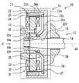
- FIG. 1 shows a schematic structure of a rotating electrical machine for an internal combustion engine.
- the internal combustion engine system 10 includes an internal combustion engine (engine 12) and a rotating electrical machine for the internal combustion engine (hereinafter simply referred to as a rotating electrical machine 15).
- An example of the use of the rotating electrical machine 15 is a generator driven by the engine 12.
- the rotating electrical machine 15 supplies power to a plurality of electric loads including a battery.
- the use of the rotating electrical machine 15 may be a generator motor.
- the rotating electrical machine 15 functions as both a generator and an electric motor.
- the rotating electrical machine 15 functions as a starter motor for starting the engine 12, for example.
- the engine 12 has a body 13.
- the body 13 is provided by a crankcase or a cover of the engine 12.
- the body 13 defines a storage chamber 13 a for storing the rotating electrical machine 15.
- the storage chamber 13a is a dry cavity filled with air, or a wet cavity in which air and lubricating oil, or air and coolant are mixed.
- the rotating electrical machine 15 radiates heat to the fluid in the storage chamber 13a.
- the fluid includes air, lubricating oil, and / or coolant.
- the engine 12 has a rotating shaft 14.
- the rotating shaft 14 is provided by a crankshaft or a shaft that interlocks with the crankshaft.
- the rotating shaft 14 is connected to the rotating electrical machine 15.
- the rotating electrical machine 15 is interlocked with the engine 12 by being mounted on the engine 12.
- the engine 12 is a vehicle engine mounted on a vehicle or a general-purpose engine.
- vehicle should be interpreted in a broad sense, and includes a moving object such as a vehicle, a ship, and an aircraft, and a fixed object such as an amusement device and a simulation device.
- a general purpose engine can be utilized as a generator and a pump, for example.
- the engine 12 is mounted on a saddle-ride type vehicle.
- the rotating electrical machine 15 is assembled to the body 13 and the rotating shaft 14.
- the rotating electrical machine 15 is an outer rotor type rotating electrical machine.
- the rotating electrical machine 15 includes a rotor 21 and a stator 31.
- axial direction refers to a direction along the central axis AX when the rotor 21, the stator 31, or the stator core 32 is regarded as a cylinder.
- radial direction refers to a radial direction when the rotor 21, the stator 31, or the stator core 32 is regarded as a cylinder.
- the rotor 21 is a field element.
- the entire rotor 21 is cup-shaped.
- the rotor 21 is fixed to the end of the rotating shaft 14.
- the rotor 21 rotates together with the rotating shaft 14.
- the rotor 21 has a cup-shaped rotor core 22.
- the rotor 21 has a permanent magnet 23 disposed on the inner surface of the rotor core 22.
- the rotor 21 provides a rotating magnetic field by the permanent magnet 23.
- the permanent magnet 23 is provided by a plurality of arc-shaped magnets.
- the rotor 21 has a holder 24 for fixing the permanent magnet 23.
- the permanent magnet 23 may be fixed by an adhesive.
- the rotor core 22 is connected to the rotating shaft 14.
- the rotating shaft 14 has an outer surface 14 a for receiving the rotor core 22.
- the outer surface 14a is a tapered surface that tapers.
- the rotor core 22 and the rotary shaft 14 are coupled via a rotational positioning mechanism such as key fitting.
- the rotor core 22 is fastened and fixed to the rotating shaft 14 by a nut 14b which is a fixing member.
- the rotor core 22 provides a yoke for a permanent magnet described later.
- the rotor core 22 is made of a magnetic metal.
- the rotor core 22 has an inner cylinder 22a, an outer cylinder 22b, and a bottom plate 22c.
- the inner cylinder 22 a is connected to the rotating shaft 14.
- the inner cylinder 22a provides a boss portion.
- the outer cylinder 22b is cylindrical.
- the outer cylinder 22b is located on the radially outer side of the inner cylinder 22a and away from the inner cylinder 22a.
- the outer cylinder 22b supports the permanent magnet 23 on the inner surface.
- the bottom plate 22c is annular.
- the bottom plate 22c extends to one end of the outer cylinder.
- the bottom plate 22c extends between the inner cylinder 22a and the outer cylinder 22b.
- the inner cylinder 22a has a through hole that receives the rotating shaft 14.
- the inner cylinder 22a has an inner surface 22d.
- the inner surface 22d is a tapered surface that contacts the outer surface 14a.
- the inner cylinder 22a, the outer cylinder 22b, and the bottom plate 22c are integrally formed of a continuous material.
- the inner cylinder 22a, the outer cylinder 22b, and the bottom plate 22c may be provided by a plurality of members.
- the boss portion that provides the inner cylinder 22a may be provided by a separate member and connected by a connecting member such as a rivet.
- the bottom plate 22c has a through hole 22e.
- the through hole 22 e communicates the inside and outside of the cup-shaped rotor 21.
- the through hole 22e is located on the radially outer side in the annular range provided by the bottom plate 22c.
- the through hole 22e opens to the inside of the rotor 21 at one end.
- the through hole 22e opens at only the axial end surface of the bottom plate 22c at the other end.
- the holder 24 is a cup-shaped member.
- the holder 24 extends from the end surface of the permanent magnet 23 over the inner surface of the permanent magnet 23 and the inner surface of the bottom plate 22c.
- the holder 24 is fixed to the bottom plate 22c by a fixing member such as a rivet.
- the holder 24 fixes the permanent magnet 23 to the rotor core 22.
- the holder 24 provides a radially inner surface 24a.
- the radially inner surface 24 a is also the inner surface of the rotor 21.
- the holder 24 is made of a thin nonmagnetic metal.
- the holder 24 is formed so as not to cover the through hole 22e.
- the holder 24 may have a through hole corresponding to the through hole 22e.
- the through hole 22 e is recognized not only as a hole in the rotor core 22 but also as a hole in the rotor 21.
- the through hole 22 e communicates the inside and outside of the rotor 21.
- the stator 31 is an armature.
- the stator 31 is an annular member.
- the stator 31 is an outer salient pole type stator.
- the stator 31 is fixed to the body 13.
- the stator 31 has a through hole that can receive the rotating shaft 14 and the inner cylinder 22a.
- the stator 31 has an outer peripheral surface that faces the inner surface of the rotor 21 via a gap.
- the stator 31 has a stator core 32.
- the stator core 32 is disposed inside the rotor 21.
- the stator core 32 is fixed to the body 13.
- the shape of the stator core 32 is characterized by an annular portion provided on the radially inner side and a plurality of teeth (saliency poles) provided on the radially outer side.
- the stator 31 has a stator coil 33 attached to a stator core 32.
- the stator coil 33 is attached to a part of the stator core 32.
- the stator coil 33 is wound around the stator core 32.
- the stator coil 33 provides a single-phase winding or a multi-phase winding.
- the stator coil 33 is disposed on the radially outer teeth of the stator core 32.
- the stator coil 33 provides an armature winding.
- the stator core 32 is fixed to the body 13 by bolts 35 that are fixing members.
- the bolt 35 passes through the stator core 32.
- the bolt 35 fixes the stator core 32 to the cover of the body 13.
- the bolt 35 can be regarded as one part of the rotating electrical machine 15 or one part of the engine 12.
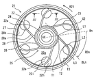
- FIG. 2 is a plan view of the rotor 21 in the direction of arrow II in FIG.
- the arrow R21 is the rotation direction R21 of the rotor 21.
- the front side of the object with respect to the direction of the rotation direction R21 may be referred to as a forward direction
- the rear side of the object with respect to the rotation direction R21 may be referred to as a backward direction.
- the positions of the plurality of through holes 22e in the rotor 21 are drawn relatively accurately.
- the rotor 21 has a plurality of through holes 22e.
- the plurality of through holes 22e are arranged at equal intervals.
- the plurality of through-holes 22e are spaced apart from each other on the inner surface in the axial direction of the rotor 21.
- the inner surface in the axial direction of the rotor 21 extends between two through holes 22e adjacent in the circumferential direction.
- the through hole 22 e is located on the radially inner side on the inner surface in the axial direction of the rotor 21.
- the through hole 22 e is close to the radially inner surface 24 a of the rotor 21.
- the through hole 22e is clearly separated from the inner cylinder 22a.
- the inner surface in the axial direction of the rotor 21 extends between the inner cylinder 22a and the through hole 22e. There is a limited axial inner surface between the radial inner surface 24a and the through hole 22e. Note that the edge of the through hole 22e may be in contact with the radially inner surface 24a.
- the through hole 22e is a circular hole.
- the rotating electrical machine 15 includes a fan 25.
- the fan 25 includes an inner ring 26, an outer ring 27, and a divided body 28 that extends between the inner ring 26 and the outer ring 27.
- the divided body 28 crosses over the through hole 22e so as to divide the through hole 22e.
- the divided body 28 is also called a cross section, a blade, or a rib.
- the divided body 28 has an inner ring connecting portion C1 that connects the inner ring 26 and the divided body 28, and an outer ring connecting portion C2 that connects the outer ring 27 and the divided body 28.
- the inner ring connection portion C1 is also called a first connection portion.
- the outer ring connection portion C2 is also called a second connection portion.
- the inner ring connection portion C1 and the outer ring connection portion C2 are offset in the rotation direction R21. That is, the through hole 22e is positioned between the inner ring connection portion C1 and the outer ring connection portion C2.
- the inner ring 26 is fixed by a flange 22f formed on the inner cylinder 22a.
- the fan 25 can be fixed to the rotor 21 by various fixing mechanisms such as caulking, adhesion, and press fitting by the flange 22f.
- the fan 25 extends from the inner cylinder 22 a along the inner surface in the axial direction of the rotor 21.
- the fan 25 reaches the radially outer edge of the axial inner surface of the rotor 21 via the axial inner surface of the rotor 21.
- the fan 25 is a part of the rotor 21.
- the fan 25 is made of resin.
- the fan 25 may be made of metal such as aluminum.
- the fan 25 has a plurality of divided bodies 28.
- the some division body 28 is arrange
- the plurality of divided bodies 28 are arranged in a distributed manner apart from each other on the inner surface in the axial direction of the rotor 21.
- the single divided body 28 extends outward from the inner ring 26 in the radial direction.
- the split body 28 extends from the inner ring 26 in parallel to the tangential direction of the inner ring 26.
- the divided body 28 includes a straight portion 28a and a curved portion 28b.
- the straight line portion 28a occupies a radially inner portion than the curved portion 28b.
- the curved portion 28b occupies a radially outer portion than the straight portion 28a.
- the curved portion 28b is curved so as to be wound in the backward direction.
- the divided body 28 reaches the outer ring 27 after passing through the straight portion 28a and the curved portion 28b.
- the divided body 28 has a receding angle RDn.
- the receding angle RDn is an inclination angle of the divided body 28 with respect to the radial direction.
- the divided body 28 is inclined with respect to the radial direction so as to gradually move backward in the rotational direction R21 from the radially inner side toward the radially outer side.
- a divided body axis BLn is assumed as the center of one divided body 28.
- the center of the straight portion 28a of the divided body 28 is defined as a divided body axis BLn.
- shaft Rn which passes along the intersection of the inner ring
- the receding angle RDn of the divided body 28 is indicated by an arrow.
- the curved portion 28b is bent toward the rear of the divided body 28 with respect to the rotation direction R21.
- the center that defines the curved portion 28b is located behind the divided body 28 in the rotation direction R21.
- the divided body 28 extends from the inner ring 26 toward the outer ring 27 with a receding angle RDn.
- the receding angle RDn may be defined by the entirety of the straight line portion 28a and the curved portion 28b. Also in this case, the divided body 28 has a receding angle.
- the split body 28 has a front edge that is the front side in the rotation direction R21 and a rear edge that is the rear side in the rotation direction R21.
- the leading edge extends between the radially inner inner end L1 and the radially outer outer end L3.
- the front edge is curved so as to be convex toward the front in the rotation direction R21.
- the leading edge has a boundary point L2 between the straight line portion 28a and the curved line portion 28b.
- the trailing edge extends between a radially inner inner end point T1 and a radially outer outer end point T3.
- the trailing edge is curved so as to be concave toward the front in the rotation direction R21.
- the trailing edge has a boundary point T2 between the straight line portion 28a and the curved portion 28b.
- the divided body 28 is disposed in the rotor 21.
- the divided body 28 is disposed on the bottom plate 22c inside the outer cylinder 22b.
- the plurality of divided bodies 28 are in contact with the surface inside the rotor 21, for example, the surface of the bottom plate 22 c.
- the division body 28 is arrange
- the plurality of divided bodies 28 are arranged radially at equal intervals.
- the plurality of divided bodies 28 are arranged at the same angular intervals as the plurality of through holes 22e.
- the plurality of divided bodies 28 are arranged in a spiral shape that gradually spreads from the inner cylinder 22 a toward the outer cylinder 22 b along the rotation direction of the rotor 21. All the divided bodies 28 have the same shape.
- a cavity 22g corresponding to the axial height of the divided body 28 is defined between two divided bodies 28 adjacent in the circumferential direction.
- the cavity 22g has a fan shape.
- the cavity 22g gradually changes in the backward direction as it goes from the radially inner end to the radially outer end. Since the divided body 28 has the receding angle RDn, the flow gradually generates from the radially inner side to the radially outer side along the divided body 28.
- the flow includes various fluid flows such as air, a mixture containing oil, and a liquid.
- the single divided body 28 is arranged so as to divide one through hole 22e.
- the divided body 28 is disposed so as to pass through substantially the center of the through hole 22e.
- the divided body 28 is arranged so that the curved portion 28b is positioned on the through hole 22e.
- the divided body 28 is arranged so that the curved portion 28b is mainly positioned on the through hole 22e.
- At least one divided body 28 crosses over at least one through hole 22e.
- At least one divided body 28 divides one through hole 22e.
- the divided body 28 is disposed so as to divide the through hole 22e into a first region 22h and a second region 22i.
- the first region 22h and the second region 22i are in communication with the fluid.
- the divided body 28 obliquely crosses the top of the through hole 22e while being inclined with respect to the radial direction.
- the divided body 28 crosses the through hole 22e obliquely while extending in the backward direction on the through hole 22e.
- the boundary points L2 and T2 are located on the through hole 22e.
- All of the plurality of divided bodies 28 divide the plurality of through holes 22e.
- All of the plurality of through holes 22 e are divided by a plurality of divided bodies 28. Each of the plurality of divided bodies 28 crosses over each of the plurality of through holes 22e.
- the divided body 28 is continuously formed from the inner cylinder 22a to the outer cylinder 22b.
- the divided body 28 is disposed so as to straddle the through hole 22e. Further, the divided body 28 is also disposed on the side surface facing the stator 31 in the rotor 21.
- the divided bodies 28 are desirably arranged in this way. As a result, an interaction with air described later occurs.
- the first region 22h is located in front of the second region 22i with respect to the rotation direction R21. Therefore, the first region 22h is also referred to as a front region.
- the second region 22i is located behind the first region 22h with respect to the rotation direction R21. Therefore, the second region 22i is also called a rear region.
- the area of the first region 22h is smaller than the area of the second region 22i. The difference in area contributes to generation of a pressure difference described later.
- the divided body 28 Since the divided body 28 has the receding angle RDn, a characteristic shape of the first region 22h and the second region 22i is obtained in the through hole 22e.
- the through hole 22e is divided into a first region 22h and a second region 22i by a curved portion 28b having a large receding angle.
- the first region 22h is located outside the second region 22i in the radial direction. Therefore, the first region 22h is also called an outer region.
- the second region 22i is located inside the first region 22h in the radial direction. Therefore, the second region 22i is also referred to as an inner region.
- the receding angle RDn gives the through hole 22e not only the characteristic shape of the front region and the rear region, but also the characteristic shape of the outer region and the inner region.
- FIG. 3 shows a schematic cross section taken along line III-III in FIG. Here, the bottom plate 22c and the fan 25 are illustrated.
- the air outside the rotor 21 flows as an outer flow OTF, and the air inside the rotor 21 flows as an inner flow INF.
- the divided body 28 generates an upward flow LF that flows so as to avoid the divided body 28.
- the pressure rises on the front side LS of the divided body 28.
- a pressure drop occurs in the rear side TS of the divided body 28, a pressure drop occurs.
- the divided body 28 is positioned so as to divide the through hole 22e into a first region 22h and a second region 22i.
- the split body 28 generates an outward flow OWF and an inward flow IWF that pass through the through hole 22e.
- an outward flow OWF is generated from the inner side to the outer side of the rotor 21.
- an inward flow IWF from the outside to the inside of the rotor 21 is generated. Thereby, the flow of the fluid through the through hole 22e is promoted.
- the fluid flow promotes heat dissipation of the rotor 21 and heat dissipation of the stator 31.
- the divided body 28 generates a component inclined in the radial direction.
- the first region 22h which is an outer region, gradually transitions radially outward along the divided body 28.
- the split body 28 generates a flow from the radially inner side to the radially outer side due to the receding angle RDn.
- the split body 28 generates an outward flow OWF inclined from the radially inner side to the radially outer side.
- the outward flow OWF in the first region 22h promotes discharge from the radially inner side of the rotor 21 to the radially outer side.
- the second region 22 i that is the inner region gradually transitions radially outward along the divided body 28.
- the split body 28 generates a flow from the radially inner side to the radially outer side due to the receding angle RDn.
- the divided body 28 generates an inward flow IWF inclined from the radially inner side to the radially outer side.
- the inward flow IWF in the second region 22 i promotes introduction from the radially inner side of the rotor 21 to the radially outer side.
- the above embodiment includes the resin fan 25.
- the fan 25 may be made of metal.
- the fan 25 is preferably a non-magnetic material.
- the non-magnetic fan 25 prevents magnetic flux leakage and, in addition, suppresses iron loss in the fan 25 caused by the leakage magnetic flux.
- the fan 25 may be provided by the holder 24.
- a raised portion corresponding to the divided body 28 may be formed in a part of the holder 24.
- the holder 24 may be insert-molded into the resin fan 25.
- the plurality of through holes 22e are arranged at equiangular intervals. Further, the plurality of through holes 22e are separated from the central axis AX by an equal distance. Instead, the plurality of through holes 22e may be arranged at unequal intervals. The plurality of through holes 22e may be dispersed with respect to the distance from the central axis AX. For example, the plurality of through holes 22e may be alternately different in distance from the central axis AX.
- the dividing body 28 may divide the through hole 22e.
- the divided body 28 only needs to cross the through hole 22e, and various modifications can be made by using ribs or fins.
- the curved portion 28b is mainly disposed on the through hole 22e.
- the straight portion 28a and the curved portion 28b may be disposed on the through hole 22e.
- only the curved portion 28b may be disposed on the through hole 22e.
- only the straight portion 28a may be disposed on the through hole 22e.
- the plurality of divided bodies 28 and the plurality of through holes 22e are associated with each other on a one-to-one basis. This configuration contributes to high efficiency. Instead of this, there may be a through hole 22e in which the divided body 28 is not disposed. Further, there may be a divided body 28 that is not disposed in the through hole 22e.
- the through hole 22e can include a plurality of through holes having different diameters.
Landscapes
- Engineering & Computer Science (AREA)
- Power Engineering (AREA)
- Chemical & Material Sciences (AREA)
- Combustion & Propulsion (AREA)
- Mechanical Engineering (AREA)
- General Engineering & Computer Science (AREA)
- Motor Or Generator Cooling System (AREA)
- Iron Core Of Rotating Electric Machines (AREA)
Abstract
ロータ21は、ロータコア22を有する。ロータコア22は、筒状の外筒22b、および外筒22bの一端に広がる底板22cを有する。底板22cは、底板22cを貫通する貫通穴22eを有する。ロータ21は、分割体28を有する。分割体28は、貫通穴22eを第1領域22hと第2領域22iとに分割する。分割体28は、貫通穴22eの上を横切っている。回転電機は、第1領域22hにおける流れと、第2領域22iにおける流れとを利用する。
Description
この出願は、2018年3月27日に日本に出願された特許出願第2018-059818号を基礎としており、基礎の出願の内容を、全体的に、参照により援用している。
この明細書における開示は、内燃機関用回転電機およびそのロータに関する。
特許文献1および特許文献2は、内燃機関用回転電機およびそのロータを開示する。内燃機関用回転電機は、ファンを備えている。従来技術として列挙された先行技術文献の記載内容は、この明細書における技術的要素の説明として、参照により援用される。
特許文献1の構成では、ファン部品が、回転電機の内部に設けられる。ファンは、回転電機、とりわけロータの内部で流れを生成する。一方で、特許文献2は、ロータの外からオイルを含む霧の流れを導入する。内燃機関用回転電機では、効率的に流れを生成することが求められている。上述の観点において、または言及されていない他の観点において、内燃機関用回転電機およびそのロータにはさらなる改良が求められている。
開示されるひとつの目的は、ロータの内部に配置された部品によって流れを効率的に生成する内燃機関用回転電機およびロータを提供することである。
ここに開示された内燃機関用回転電機のロータは、筒状の外筒(22b)、および外筒の一端に広がる底板(22c)を有し、底板を貫通する貫通穴(22e)を有するロータコア(22)と、外筒の内側に配置され、貫通穴を第1領域(22h)と第2領域(22i)とに分割するように貫通穴の上を横切っている分割体(28)とを備える。
開示される内燃機関用回転電機のロータは、分割体によって貫通穴を通る流れを生成する。分割体は、貫通穴を第1領域と第2領域とに分割している。分割体は、第1領域において流れを生成し、第2領域においても流れを生成する。ロータは、第1領域における流れと、第2領域における流れとを利用することができる。この結果、ロータの内部に配置された分割体によって流れを効率的に生成する内燃機関用回転電機のロータが提供される。
ここに開示された内燃機関用回転電機は、上記ロータ(21)と、ロータと対向するステータ(31)とを備える。
この明細書における開示された複数の態様は、それぞれの目的を達成するために、互いに異なる技術的手段を採用する。請求の範囲およびこの項に記載した括弧内の符号は、後述する実施形態の部分との対応関係を例示的に示すものであって、技術的範囲を限定することを意図するものではない。この明細書に開示される目的、特徴、および効果は、後続の詳細な説明、および添付の図面を参照することによってより明確になる。
図面を参照しながら、複数の実施形態を説明する。複数の実施形態において、機能的におよび/または構造的に対応する部分および/または関連付けられる部分には同一の参照符号、または百以上の位が異なる参照符号が付される場合がある。対応する部分および/または関連付けられる部分については、他の実施形態の説明を参照することができる。
第1実施形態
図1は、内燃機関用回転電機の模式的な構造を示す。内燃機関システム10は、内燃機関(エンジン12)と、内燃機関用回転電機(以下、単に回転電機15という)とを備える。回転電機15の用途の一例は、エンジン12によって駆動される発電機である。この場合、回転電機15は、バッテリを含む複数の電気負荷に電力を供給する。回転電機15の用途は、発電電動機でもよい。この場合、回転電機15は、発電機としても、電動機としても機能する。この場合、回転電機15は、例えば、エンジン12を始動するためのスタータモータとして機能する。
図1は、内燃機関用回転電機の模式的な構造を示す。内燃機関システム10は、内燃機関(エンジン12)と、内燃機関用回転電機(以下、単に回転電機15という)とを備える。回転電機15の用途の一例は、エンジン12によって駆動される発電機である。この場合、回転電機15は、バッテリを含む複数の電気負荷に電力を供給する。回転電機15の用途は、発電電動機でもよい。この場合、回転電機15は、発電機としても、電動機としても機能する。この場合、回転電機15は、例えば、エンジン12を始動するためのスタータモータとして機能する。
エンジン12は、ボディ13を有する。ボディ13は、エンジン12のクランクケースまたはカバーによって提供されている。ボディ13は、回転電機15を収容するための収容室13aを区画している。収容室13aは、空気で満たされた乾式空洞、または空気と潤滑オイル、若しくは空気と冷却液が混在する湿式空洞である。回転電機15は、この収容室13a内の流体に放熱する。流体は、空気、潤滑オイル、および/または冷却液を含む。エンジン12は、回転軸14を有する。回転軸14は、クランクシャフトまたはクランクシャフトと連動するシャフトによって提供されている。回転軸14は、回転電機15と連結されている。
回転電機15は、エンジン12に装着されることによって、エンジン12と連動する。エンジン12は、乗り物に搭載された乗り物用エンジン、または汎用エンジンである。ここで、乗り物の語は、広義に解釈されるべきであり、車両、船舶、航空機などの移動体、および、アミューズメント機器、およびシミュレーション機器などの固定物を含む。また、汎用エンジンは、例えば、発電機、およびポンプとして利用可能である。この実施形態では、エンジン12は、鞍乗り型の車両に搭載されている。
回転電機15は、ボディ13と回転軸14とに組み付けられている。回転電機15は、アウタロータ型の回転電機である。回転電機15は、ロータ21と、ステータ31とを有する。以下の説明において、軸方向の語は、ロータ21、ステータ31、またはステータコア32を円筒と見なした場合の中心軸AXに沿う方向を指す。径方向の語は、ロータ21、ステータ31、またはステータコア32を円筒と見なした場合の径方向を指す。
ロータ21は、界磁子である。ロータ21は、全体がカップ状である。ロータ21は、回転軸14の端部に固定される。ロータ21は、回転軸14とともに回転する。ロータ21は、カップ状のロータコア22を有する。ロータ21は、ロータコア22の内面に配置された永久磁石23を有する。ロータ21は、永久磁石23によって回転磁界を提供する。永久磁石23は、複数の円弧状磁石によって提供されている。ロータ21は、永久磁石23を固定するためのホルダ24を有する。永久磁石23は、接着剤によって固定されていてもよい。
ロータコア22は、回転軸14に連結される。回転軸14は、ロータコア22を受けるために、外面14aを有する。外面14aは、先細りのテーパ面である。ロータコア22と回転軸14とは、キー嵌合などの回転方向の位置決め機構を介して連結されている。ロータコア22は、固定部材であるナット14bによって回転軸14に締め付けられ、固定されている。ロータコア22は、後述する永久磁石のためのヨークを提供する。ロータコア22は、磁性金属製である。
ロータコア22は、内筒22aと、外筒22bと、底板22cとを有する。内筒22aは、回転軸14に連結される。内筒22aは、ボス部を提供する。外筒22bは、筒状である。外筒22bは、内筒22aの径方向外側に、内筒22aから離れて位置している。外筒22bは、内面に永久磁石23を支持している。底板22cは、環状である。底板22cは、外筒の一端に広がっている。底板22cは、内筒22aと外筒22bとの間に広がっている。
内筒22aは、回転軸14を受け入れる貫通穴を有する。内筒22aは、内面22dを有する。内面22dは、外面14aと接触するテーパ面である。この実施形態では、内筒22aと、外筒22bと、底板22cとは、連続した材料によって一体的に形成されている。内筒22aと、外筒22bと、底板22cとは、複数の部材によって提供されていてもよい。例えば、内筒22aを提供するボス部分を別部材によって提供し、リベットなどの連結部材によって連結してもよい。
底板22cは、貫通穴22eを有する。貫通穴22eは、カップ状のロータ21の内外を連通している。貫通穴22eは、底板22cが提供する環状範囲のうち、径方向外側に位置している。貫通穴22eは、一端においてロータ21の内側に開口している。貫通穴22eは、他端において底板22cの軸方向端面のみに開口している。
ホルダ24は、カップ状の部材である。ホルダ24は、永久磁石23の端面から、永久磁石23の内面、および底板22cの内面にわたって延びている。ホルダ24は、底板22cにリベットなどの固定部材によって固定されている。ホルダ24は、永久磁石23をロータコア22に固定する。ホルダ24は、径方向内面24aを提供している。径方向内面24aは、ロータ21の内面でもある。ホルダ24は、薄い非磁性金属製である。
ホルダ24は、貫通穴22eを覆うことがないように形成されている。ホルダ24は、貫通穴22eに相当する貫通穴を有する場合がある。この結果、貫通穴22eは、ロータコア22における穴だけでなく、ロータ21における穴として認識される。貫通穴22eは、ロータ21の内外を連通している。
ステータ31は、電機子である。ステータ31は、環状の部材である。ステータ31は、外突極型のステータである。ステータ31は、ボディ13に固定されている。ステータ31は、回転軸14と内筒22aとを受け入れることができる貫通穴を有する。ステータ31は、ロータ21の内面とギャップを介して対向する外周面を有する。
ステータ31は、ステータコア32を有する。ステータコア32は、ロータ21の内側に配置されている。ステータコア32は、ボディ13に固定されている。ステータコア32の形状は、径方向内側に設けられた環状部分と、径方向外側に設けられた複数のティース(突極)とで特徴付けられている。
ステータ31は、ステータコア32に装着されたステータコイル33を有する。ステータコイル33は、ステータコア32の一部に装着されている。ステータコイル33は、ステータコア32に巻回されている。ステータコイル33は、単相巻線、または多相巻線を提供する。ステータコイル33は、ステータコア32の径方向外側のティースに配置されている。ステータコイル33は、電機子巻線を提供する。ステータコア32は、固定部材であるボルト35によってボディ13に固定されている。ボルト35は、ステータコア32を貫通している。ボルト35は、ボディ13のカバーにステータコア32を固定している。ボルト35は、回転電機15の一部品、またはエンジン12の一部品とみることができる。
図2は、図1の矢印II方向におけるロータ21の平面図である。矢印R21は、ロータ21の回転方向R21である。以下の説明において、回転方向R21の方向に関して対象物の前方側は、前進方向とも呼ばれ、回転方向R21に関して対象物の後方側は後退方向と呼ばれることがある。ロータ21における複数の貫通穴22eの位置などは、比較的正確に描かれている。
ロータ21は、複数の貫通穴22eを有する。複数の貫通穴22eは、互いに等間隔に配置されている。複数の貫通穴22eは、ロータ21の軸方向内面において互いに離れて分散的に配置されている。周方向に隣り合う2つの貫通穴22eの間には、ロータ21の軸方向内面が広がっている。貫通穴22eは、ロータ21の軸方向内面において径方向外側に位置している。貫通穴22eは、ロータ21の径方向内面24aに近接している。貫通穴22eは、内筒22aから明白に離れている。内筒22aと貫通穴22eとの間には、ロータ21の軸方向内面が広がっている。径方向内面24aと貫通穴22eとの間には、限られた軸方向内面がある。なお、貫通穴22eの縁は、径方向内面24aに接していてもよい。貫通穴22eは、円形の穴である。
図1に戻り、回転電機15は、ファン25を有する。ファン25は、内輪26と、外輪27と、内輪26と外輪27との間に延びる分割体28とを有する。分割体28は、貫通穴22eを分割するように貫通穴22eの上を横切っている。分割体28は、横断部、ブレード、またはリブとも呼ばれる。
分割体28は、内輪26と分割体28とを接続する内輪接続部C1と、外輪27と分割体28とを接続する外輪接続部C2とを有する。内輪接続部C1は、第1接続部とも呼ばれる。外輪接続部C2は、第2接続部とも呼ばれる。内輪接続部C1と外輪接続部C2とは、回転方向R21において、オフセットしている。つまり、内輪接続部C1と外輪接続部C2との間に、貫通穴22eが位置付けられている。
内輪26は、内筒22aに形成されたフランジ22fによって固定されている。ファン25は、ロータ21に対して、フランジ22fによるかしめ、接着、圧入など多様な固定機構によって固定することができる。ファン25は、内筒22aから、ロータ21の軸方向内面に沿って延びている。ファン25は、ロータ21の軸方向内面を経由して、ロータ21の軸方向内面の径方向外側縁まで到達している。ファン25は、ロータ21の一部分である。ファン25は、樹脂製である。ファン25は、アルミニウムなどの金属製でもよい。
図2において、ファン25は、複数の分割体28を有する。複数の分割体28は、互いに等間隔に配置されている。複数の分割体28は、ロータ21の軸方向内面において互いに離れて分散的に配置されている。
ひとつの分割体28は、内輪26から径方向外側に向けて延び出している。分割体28は、内輪26から、内輪26の接線方向と平行に延び出している。分割体28は、直線部分28aと、曲線部分28bとを有する。直線部分28aは、曲線部分28bよりも径方向内側部分を占める。曲線部分28bは、直線部分28aよりも径方向外側部分を占めている。曲線部分28bは、後退方向へ巻き込むように湾曲している。分割体28は、直線部分28aと、曲線部分28bとを経由した後に、外輪27に到達している。
分割体28は、後退角RDnを有する。後退角RDnは、径方向に対する分割体28の傾斜角である。分割体28は、径方向内側から径方向外側に向けて、徐々に回転方向R21の後方へ後退するように、径方向に対して傾斜している。ひとつの分割体28の中心として分割体軸BLnを想定する。ここでは、分割体28の直線部分28aの中心を分割体軸BLnとする。さらに、内輪26とひとつの分割体28との交点を通る径方向軸Rnを想定する。この場合、分割体28の後退角RDnは、矢印で示される。曲線部分28bは、回転方向R21に関して分割体28より後ろに向けて曲がっている。言い換えると、曲線部分28bを規定する中心は、回転方向R21に関して分割体28より後ろに位置している。分割体28は、内輪26から外輪27に向けて、後退角RDnをもって延びている。後退角RDnは、直線部分28aと、曲線部分28bとの全体によって定義されてもよい。この場合も、分割体28は、後退角を有する。
分割体28は、回転方向R21の前方側である前縁と、回転方向R21の後方側である後縁とを有する。前縁は、径方向内側の内端点L1と、径方向外側の外端点L3との間にわたって延びている。前縁は、回転方向R21の前方へ向けて凸となるように湾曲している。前縁は、直線部分28aと、曲線部分28bとの境界点L2を有する。後縁は、径方向内側の内端点T1と、径方向外側の外端点T3との間にわたって延びている。後縁は、回転方向R21の前方へ向けて凹となるように湾曲している。後縁は、直線部分28aと、曲線部分28bとの境界点T2を有する。
分割体28は、ロータ21内に配置されている。分割体28は、外筒22bの内側における底板22cの上に配置されている。複数の分割体28は、ロータ21内の面、例えば底板22cの面に接している。分割体28は、底板22cのステータ31と対向する面に配置されている。
複数の分割体28は、放射状に等間隔で配置されている。複数の分割体28は、複数の貫通穴22eと同じ角度間隔で配置されている。複数の分割体28は、ロータ21の回転方向に沿って徐々に内筒22aから外筒22bに向けて広がる渦巻状に配置されている。すべての分割体28は、同じ形状である。
周方向に隣り合う2つの分割体28の間には、分割体28の軸方向高さに相当する空洞22gが区画されている。空洞22gは、扇形である。空洞22gは、径方向内端から径方向外端へ向かうにつれて、徐々に後退方向へ推移している。分割体28は、後退角RDnを有しているから、分割体28に沿って、徐々に径方向内側から径方向外側へ向かう流れを生成する。流れは、空気の場合と、オイルを含む混合気の場合と、液体の場合となど多様な流体の流れを含む。
ひとつの分割体28は、ひとつの貫通穴22eを分割するように配置されている。分割体28は、貫通穴22eのほぼ中央を通るように配置されている。分割体28は、曲線部分28bを貫通穴22eの上に位置付けるように配置されている。分割体28は、主として曲線部分28bを貫通穴22eの上に位置付けるように配置されている。少なくともひとつの分割体28は、少なくともひとつの貫通穴22eの上を横切っている。少なくともひとつの分割体28は、ひとつの貫通穴22eを分割している。分割体28は、貫通穴22eを第1領域22hと、第2領域22iとに分割するように配置されている。第1領域22hと、第2領域22iとは、流体に対して連通状態である。分割体28は、径方向に対して傾斜しながら、貫通穴22eの上を斜めに横切っている。分割体28は、貫通穴22eの上において、後退方向へ延びながら、貫通穴22eの上を斜めに横切っている。境界点L2、T2は、貫通穴22eの上に位置している。複数の分割体28のすべては、複数の貫通穴22eを分割している。複数の貫通穴22eのすべては、複数の分割体28によって分割されている。複数の分割体28のそれぞれは、複数の貫通穴22eのそれぞれの上を横切っている。
分割体28は、内筒22aから外筒22bまで連続して形成されている。分割体28は、貫通穴22eの上に跨るように配置されている。また、分割体28は、ロータ21の内部においても、ステータ31と対向する側面に配置されている。分割体28は、このように配置されていることが望ましい。この結果、後述の空気との相互作用を生じる。
第1領域22hは、回転方向R21に関して第2領域22iより前方に位置する。よって、第1領域22hは、前方領域とも呼ばれる。第2領域22iは、回転方向R21に関して第1領域22hより後方に位置する。よって、第2領域22iは、後方領域とも呼ばれる。第1領域22hの面積は、第2領域22iの面積より小さい。面積の差は、後述する圧力差の生成に貢献する。
分割体28は、後退角RDnを有しているから、貫通穴22eにおいて、第1領域22hと第2領域22iとの特徴的な形状が得られる。特に、貫通穴22eは、後退角が大きい曲線部分28bによって第1領域22hと、第2領域22iとに分割されている。この結果、第1領域22hは、径方向に関して第2領域22iより外側に位置する。よって、第1領域22hは、外側領域とも呼ばれる。第2領域22iは、径方向に関して第1領域22hより内側に位置する。よって、第2領域22iは、内側領域とも呼ばれる。後退角RDnは、前方領域と後方領域という特徴的な形状だけでなく、外側領域と内側領域という特徴的な形状を、貫通穴22eに与える。
図3は、図2のIII-III線における模式的な断面を示す。ここでは、底板22cとファン25とが図示されている。ロータ21が回転方向R21に向けて回転すると、ロータ21の外側の空気は外側流OTFとして流れ、ロータ21の内側の空気は内側流INFとして流れる。分割体28は、分割体28を避けるように流れる上昇流LFを生成する。このとき、分割体28の前方側LSでは圧力の上昇が生じる。分割体28の後方側TSでは圧力の低下が生じる。
分割体28は、貫通穴22eを第1領域22hと第2領域22iとに分割するように位置付けられている。分割体28は、貫通穴22eを通る外向流OWF、および内向流IWFを生成する。前方側LSでは、ロータ21の内側から外側へ向かう外向流OWFが生じる。後方側TSでは、ロータ21の外側から内側へ向かう内向流IWFが生じる。これにより貫通穴22eを通る流体の流れが促進される。流体の流れは、ロータ21の放熱、およびステータ31の放熱を促進する。
さらに、外側領域と内側領域という特徴的な形状に起因して、分割体28は径方向に傾斜した成分を生成する。外側領域である第1領域22hは、分割体28に沿って径方向外側へ徐々に推移している。分割体28は、後退角RDnに起因して、径方向内側から径方向外側へ向かう流れを生じる。分割体28は、径方向内側から径方向外側へ傾いた外向流OWFを生じる。第1領域22hにおける外向流OWFは、ロータ21の径方向内側から、径方向外側への排出を促進する。
内側領域である第2領域22iは、分割体28に沿って径方向外側へ徐々に推移している。分割体28は、後退角RDnに起因して、径方向内側から径方向外側へ向かう流れを生じる。分割体28は、径方向内側から径方向外側へ傾いた内向流IWFを生じる。第2領域22iにおける内向流IWFは、ロータ21の径方向内側から、径方向外側への導入を促進する。
この結果、外向流OWFを径方向外側へ排出し、内向流IWFを径方向内側から取り入れる流れが生成される。この流れは、ひとつの貫通穴22eにおける外向流OWFと内向流IWFとの短絡を抑制する。これにより貫通穴22eを通る流体の流れが促進される。流体の流れは、ロータ21の放熱、およびステータ31の放熱を促進する。
他の実施形態
この明細書および図面等における開示は、例示された実施形態に制限されない。開示は、例示された実施形態と、それらに基づく当業者による変形態様を包含する。例えば、開示は、実施形態において示された部品および/または要素の組み合わせに限定されない。開示は、多様な組み合わせによって実施可能である。開示は、実施形態に追加可能な追加的な部分をもつことができる。開示は、実施形態の部品および/または要素が省略されたものを包含する。開示は、ひとつの実施形態と他の実施形態との間における部品および/または要素の置き換え、または組み合わせを包含する。開示される技術的範囲は、実施形態の記載に限定されない。開示されるいくつかの技術的範囲は、請求の範囲の記載によって示され、さらに請求の範囲の記載と均等の意味及び範囲内での全ての変更を含むものと解されるべきである。
この明細書および図面等における開示は、例示された実施形態に制限されない。開示は、例示された実施形態と、それらに基づく当業者による変形態様を包含する。例えば、開示は、実施形態において示された部品および/または要素の組み合わせに限定されない。開示は、多様な組み合わせによって実施可能である。開示は、実施形態に追加可能な追加的な部分をもつことができる。開示は、実施形態の部品および/または要素が省略されたものを包含する。開示は、ひとつの実施形態と他の実施形態との間における部品および/または要素の置き換え、または組み合わせを包含する。開示される技術的範囲は、実施形態の記載に限定されない。開示されるいくつかの技術的範囲は、請求の範囲の記載によって示され、さらに請求の範囲の記載と均等の意味及び範囲内での全ての変更を含むものと解されるべきである。
上記実施形態は、樹脂製のファン25を備える。これに代えて、ファン25は、金属製でもよい。ファン25は、非磁性体であることが好適である。非磁性体製のファン25は、磁束の漏洩を防止し、加えて、漏れ磁束に起因するファン25での鉄損を抑制する。また、ファン25は、ホルダ24によって提供されてもよい。例えば、ホルダ24の一部に、分割体28に相当する隆起部分を形成してもよい。また、樹脂製のファン25にホルダ24をインサート成形してもよい。
上記実施形態では、複数の貫通穴22eは、等角度間隔に配置されている。また、複数の貫通穴22eは、中心軸AXから等距離だけ離れている。これに代えて、複数の貫通穴22eは、不等間隔に配置されてもよい。また、複数の貫通穴22eは、中心軸AXからの距離に関して、分散していてもよい。例えば、複数の貫通穴22eは、中心軸AXからの距離が交互に異なっていてもよい。
分割体28は、貫通穴22eを分割すればよい。言い換えれば、分割体28は、貫通穴22eを横断すればよく、リブでもフィンでも種々の変更が可能である。上記実施形態では、貫通穴22eの上に主として曲線部分28bを配置している。これに代えて、貫通穴22eの上に、直線部分28aと曲線部分28bとを配置してもよい。また、貫通穴22eの上に、曲線部分28bだけを配置してもよい。また、貫通穴22eの上に、直線部分28aだけを配置してもよい。
上記実施形態では、複数の分割体28と、複数の貫通穴22eとが、互いに1対1に関連付けられている。この構成は、高い効率に貢献する。これに代えて、分割体28が配置されない貫通穴22eがあってもよい。また、貫通穴22eに配置されない分割体28があってもよい。また、貫通穴22eは、直径が異なる複数の貫通穴を含むことができる。
Claims (11)
- 筒状の外筒(22b)、および前記外筒の一端に広がる底板(22c)を有し、前記底板を貫通する貫通穴(22e)を有するロータコア(22)と、
前記外筒の内側に配置され、前記貫通穴を第1領域(22h)と第2領域(22i)とに分割するように前記貫通穴の上を横切っている分割体(28)とを備える内燃機関用回転電機のロータ。 - 前記第1領域は、前記ロータの回転方向(R21)に関して前記第2領域よりも前方に位置する前方領域であり、
前記第2領域は、前記ロータの回転方向に関して前記第1領域よりも後方に位置する後方領域である請求項1に記載の内燃機関用回転電機のロータ。 - 前記第1領域は、前記ロータの径方向に関して前記第2領域よりも外側に位置する外側領域であり、
前記第2領域は、前記ロータの径方向に関して前記第1領域よりも内側に位置する内側領域である請求項1または請求項2に記載の内燃機関用回転電機のロータ。 - 前記分割体は、前記貫通穴の上を前記ロータの径方向に対して斜めに横切っている請求項1から請求項3のいずれかに記載の内燃機関用回転電機のロータ。
- 前記分割体は、前記ロータの回転方向に関して後退角(RDn)をもって延びている請求項4に記載の内燃機関用回転電機のロータ。
- 前記分割体は、直線部分(28a)と、曲線部分(28b)とを有し、
前記直線部分は、前記曲線部分よりも径方向内側を占めるように配置され、
前記曲線部分は、前記直線部分よりも径方向外側を占めるように配置されている請求項1から請求項5のいずれかに記載の内燃機関用回転電機のロータ。 - 前記曲線部分が前記貫通穴の上に配置されている請求項6に記載の内燃機関用回転電機のロータ。
- 複数の前記貫通穴と、複数の前記分割体とを有し、
複数の前記分割体のそれぞれは、複数の前記貫通穴のそれぞれの上を横切っている請求項1から請求項7のいずれかに記載の内燃機関用回転電機のロータ。 - 前記分割体は、内輪(26)と外輪(27)とを備えるファン(25)の一部として提供されており、前記内輪と前記外輪との間にわたって延びており、樹脂製である請求項1から請求項8のいずれかに記載の内燃機関用回転電機のロータ。
- 前記第1領域(22h)の面積は、前記第2領域(22i)の面積より小さいことを特徴とする請求項1から請求項9のいずれかに記載の内燃機関用回転電機のロータ。
- 請求項1から請求項10のいずれかに記載のロータ(21)と、
前記ロータと対向するステータ(31)とを備える内燃機関用回転電機。
Priority Applications (4)
| Application Number | Priority Date | Filing Date | Title |
|---|---|---|---|
| EP19775826.1A EP3780360A4 (en) | 2018-03-27 | 2019-03-21 | DYNAMO-ELECTRIC MACHINE FOR INTERNAL COMBUSTION ENGINES, AND ITS ROTOR |
| CN201980021905.8A CN111903042A (zh) | 2018-03-27 | 2019-03-21 | 内燃机用旋转电机及其转子 |
| JP2020509928A JPWO2019188734A1 (ja) | 2018-03-27 | 2019-03-21 | 内燃機関用回転電機およびそのロータ |
| US17/030,098 US20210006114A1 (en) | 2018-03-27 | 2020-09-23 | Rotary electric machine for internal combustion engine and rotor thereof |
Applications Claiming Priority (2)
| Application Number | Priority Date | Filing Date | Title |
|---|---|---|---|
| JP2018-059818 | 2018-03-27 | ||
| JP2018059818 | 2018-03-27 |
Related Child Applications (1)
| Application Number | Title | Priority Date | Filing Date |
|---|---|---|---|
| US17/030,098 Continuation US20210006114A1 (en) | 2018-03-27 | 2020-09-23 | Rotary electric machine for internal combustion engine and rotor thereof |
Publications (1)
| Publication Number | Publication Date |
|---|---|
| WO2019188734A1 true WO2019188734A1 (ja) | 2019-10-03 |
Family
ID=68061782
Family Applications (1)
| Application Number | Title | Priority Date | Filing Date |
|---|---|---|---|
| PCT/JP2019/011942 Ceased WO2019188734A1 (ja) | 2018-03-27 | 2019-03-21 | 内燃機関用回転電機およびそのロータ |
Country Status (5)
| Country | Link |
|---|---|
| US (1) | US20210006114A1 (ja) |
| EP (1) | EP3780360A4 (ja) |
| JP (1) | JPWO2019188734A1 (ja) |
| CN (1) | CN111903042A (ja) |
| WO (1) | WO2019188734A1 (ja) |
Families Citing this family (1)
| Publication number | Priority date | Publication date | Assignee | Title |
|---|---|---|---|---|
| US20230188004A1 (en) | 2021-12-10 | 2023-06-15 | Black & Decker Inc. | Power tool with compact outer-rotor motor assembly |
Citations (7)
| Publication number | Priority date | Publication date | Assignee | Title |
|---|---|---|---|---|
| JPS5935547A (ja) | 1982-08-18 | 1984-02-27 | Hitachi Ltd | 内燃機関用磁石発電機 |
| JP2001045714A (ja) | 1999-08-03 | 2001-02-16 | Denso Corp | 磁石発電機及びその製造方法 |
| JP2003333801A (ja) * | 2002-05-16 | 2003-11-21 | Mitsubishi Electric Corp | 磁石発電機 |
| JP2007129818A (ja) * | 2005-11-02 | 2007-05-24 | Mitsubishi Electric Corp | 磁石発電機 |
| JP2008099506A (ja) * | 2006-10-16 | 2008-04-24 | Matsushita Electric Ind Co Ltd | 誘導電動機 |
| JP2009159763A (ja) * | 2007-12-27 | 2009-07-16 | Toshiba Industrial Products Manufacturing Corp | 回転電機 |
| JP2016525333A (ja) * | 2013-07-16 | 2016-08-22 | イクイップメイク・リミテッドEquipmake Ltd | 電動機用の固定子および回転子 |
Family Cites Families (9)
| Publication number | Priority date | Publication date | Assignee | Title |
|---|---|---|---|---|
| JPS60212613A (ja) * | 1984-04-05 | 1985-10-24 | Hitachi Ltd | 内燃機関用磁石発電機およびその冷却フアン固定方法 |
| ES2301228T3 (es) * | 1999-01-08 | 2008-06-16 | Lg Electronics Inc. | Estructura de rotor para un motor sin escobillas de tipo con rotor externo. |
| JP2001061256A (ja) * | 1999-08-20 | 2001-03-06 | Toshiba Corp | 全閉形アウタロータ回転電機 |
| KR20060031272A (ko) * | 2004-10-08 | 2006-04-12 | 주식회사 대우일렉트로닉스 | 아우터 로터형 모터용 회전자의 방열장치 |
| KR101072462B1 (ko) * | 2004-11-17 | 2011-10-11 | 주식회사 대우일렉트로닉스 | 드럼 세탁기용 아우터 로터 모터의 방열장치 |
| DE202006013319U1 (de) * | 2005-10-08 | 2007-02-15 | Ebm-Papst St. Georgen Gmbh & Co. Kg | Außenläufermotor |
| US8692432B2 (en) * | 2010-12-07 | 2014-04-08 | Regal Beloit America, Inc. | Permanent magnet rotors and methods of assembling the same |
| JP6032340B2 (ja) * | 2014-11-28 | 2016-11-24 | デンソートリム株式会社 | 内燃機関用回転電機 |
| JP6550909B2 (ja) * | 2015-05-08 | 2019-07-31 | 株式会社デンソー | 送風装置 |
-
2019
- 2019-03-21 JP JP2020509928A patent/JPWO2019188734A1/ja active Pending
- 2019-03-21 WO PCT/JP2019/011942 patent/WO2019188734A1/ja not_active Ceased
- 2019-03-21 EP EP19775826.1A patent/EP3780360A4/en not_active Withdrawn
- 2019-03-21 CN CN201980021905.8A patent/CN111903042A/zh active Pending
-
2020
- 2020-09-23 US US17/030,098 patent/US20210006114A1/en not_active Abandoned
Patent Citations (7)
| Publication number | Priority date | Publication date | Assignee | Title |
|---|---|---|---|---|
| JPS5935547A (ja) | 1982-08-18 | 1984-02-27 | Hitachi Ltd | 内燃機関用磁石発電機 |
| JP2001045714A (ja) | 1999-08-03 | 2001-02-16 | Denso Corp | 磁石発電機及びその製造方法 |
| JP2003333801A (ja) * | 2002-05-16 | 2003-11-21 | Mitsubishi Electric Corp | 磁石発電機 |
| JP2007129818A (ja) * | 2005-11-02 | 2007-05-24 | Mitsubishi Electric Corp | 磁石発電機 |
| JP2008099506A (ja) * | 2006-10-16 | 2008-04-24 | Matsushita Electric Ind Co Ltd | 誘導電動機 |
| JP2009159763A (ja) * | 2007-12-27 | 2009-07-16 | Toshiba Industrial Products Manufacturing Corp | 回転電機 |
| JP2016525333A (ja) * | 2013-07-16 | 2016-08-22 | イクイップメイク・リミテッドEquipmake Ltd | 電動機用の固定子および回転子 |
Non-Patent Citations (1)
| Title |
|---|
| See also references of EP3780360A4 |
Also Published As
| Publication number | Publication date |
|---|---|
| EP3780360A4 (en) | 2021-12-22 |
| CN111903042A (zh) | 2020-11-06 |
| US20210006114A1 (en) | 2021-01-07 |
| EP3780360A1 (en) | 2021-02-17 |
| JPWO2019188734A1 (ja) | 2021-03-11 |
Similar Documents
| Publication | Publication Date | Title |
|---|---|---|
| KR101738208B1 (ko) | 전기 기계 냉각 시스템 및 방법 | |
| KR101664047B1 (ko) | 계자권선형 구동모터의 회전자 | |
| JP5622777B2 (ja) | 圧縮機又は真空機 | |
| US7411330B2 (en) | Rotating electric machine | |
| US7114937B2 (en) | Magneto-generator, method of manufacturing the same and resin molding die assembly for manufacturing the same | |
| EP3144538B1 (en) | Electric pump | |
| CN106050725A (zh) | 电动水泵 | |
| JP6085267B2 (ja) | 回転電機 | |
| US20090085417A1 (en) | Rotor assembly, in which at least one inter-claw space is sealed by the fan | |
| JP6938767B2 (ja) | 内燃機関用回転電機およびそのロータ | |
| US20210006114A1 (en) | Rotary electric machine for internal combustion engine and rotor thereof | |
| JP2016197950A (ja) | 回転電機 | |
| US9500086B2 (en) | Impeller and electric-motor driven water pump having the same | |
| JP2017184351A (ja) | 回転電機 | |
| JP2014100038A (ja) | 回転電機の固定子 | |
| EP1249918A1 (en) | Rotor for a permanent magnet type electrical machine | |
| US11575287B2 (en) | Arrangement for reducing eddy current losses of an outer rotor electric machine | |
| JP2018031329A (ja) | 電動流体ポンプ | |
| JP2018031330A (ja) | 電動流体ポンプ | |
| JP3680664B2 (ja) | 磁石式発電機 | |
| CN114530958B (zh) | 一种爪极式发电机 | |
| EP1555739A1 (en) | Self-ventilating magneto-generator | |
| JP2026035972A (ja) | ポンプ装置 | |
| CN121816681A (zh) | 转子和液压泵 | |
| JP2018038179A (ja) | モータ |
Legal Events
| Date | Code | Title | Description |
|---|---|---|---|
| 121 | Ep: the epo has been informed by wipo that ep was designated in this application |
Ref document number: 19775826 Country of ref document: EP Kind code of ref document: A1 |
|
| ENP | Entry into the national phase |
Ref document number: 2020509928 Country of ref document: JP Kind code of ref document: A |
|
| NENP | Non-entry into the national phase |
Ref country code: DE |
|
| ENP | Entry into the national phase |
Ref document number: 2019775826 Country of ref document: EP Effective date: 20201027 |