WO2019188848A1 - 光合成速度計測システム - Google Patents
光合成速度計測システム Download PDFInfo
- Publication number
- WO2019188848A1 WO2019188848A1 PCT/JP2019/012260 JP2019012260W WO2019188848A1 WO 2019188848 A1 WO2019188848 A1 WO 2019188848A1 JP 2019012260 W JP2019012260 W JP 2019012260W WO 2019188848 A1 WO2019188848 A1 WO 2019188848A1
- Authority
- WO
- WIPO (PCT)
- Prior art keywords
- air
- sensor
- carbon dioxide
- covering
- lid
- Prior art date
- Legal status (The legal status is an assumption and is not a legal conclusion. Google has not performed a legal analysis and makes no representation as to the accuracy of the status listed.)
- Ceased
Links
Images




Classifications
-
- A—HUMAN NECESSITIES
- A01—AGRICULTURE; FORESTRY; ANIMAL HUSBANDRY; HUNTING; TRAPPING; FISHING
- A01G—HORTICULTURE; CULTIVATION OF VEGETABLES, FLOWERS, RICE, FRUIT, VINES, HOPS OR SEAWEED; FORESTRY; WATERING
- A01G7/00—Botany in general
-
- G—PHYSICS
- G01—MEASURING; TESTING
- G01N—INVESTIGATING OR ANALYSING MATERIALS BY DETERMINING THEIR CHEMICAL OR PHYSICAL PROPERTIES
- G01N21/00—Investigating or analysing materials by the use of optical means, i.e. using sub-millimetre waves, infrared, visible or ultraviolet light
- G01N21/17—Systems in which incident light is modified in accordance with the properties of the material investigated
- G01N21/25—Colour; Spectral properties, i.e. comparison of effect of material on the light at two or more different wavelengths or wavelength bands
- G01N21/31—Investigating relative effect of material at wavelengths characteristic of specific elements or molecules, e.g. atomic absorption spectrometry
-
- G—PHYSICS
- G01—MEASURING; TESTING
- G01N—INVESTIGATING OR ANALYSING MATERIALS BY DETERMINING THEIR CHEMICAL OR PHYSICAL PROPERTIES
- G01N33/00—Investigating or analysing materials by specific methods not covered by groups G01N1/00 - G01N31/00
- G01N33/0098—Plants or trees
-
- Y—GENERAL TAGGING OF NEW TECHNOLOGICAL DEVELOPMENTS; GENERAL TAGGING OF CROSS-SECTIONAL TECHNOLOGIES SPANNING OVER SEVERAL SECTIONS OF THE IPC; TECHNICAL SUBJECTS COVERED BY FORMER USPC CROSS-REFERENCE ART COLLECTIONS [XRACs] AND DIGESTS
- Y02—TECHNOLOGIES OR APPLICATIONS FOR MITIGATION OR ADAPTATION AGAINST CLIMATE CHANGE
- Y02A—TECHNOLOGIES FOR ADAPTATION TO CLIMATE CHANGE
- Y02A40/00—Adaptation technologies in agriculture, forestry, livestock or agroalimentary production
- Y02A40/10—Adaptation technologies in agriculture, forestry, livestock or agroalimentary production in agriculture
- Y02A40/25—Greenhouse technology, e.g. cooling systems therefor
Definitions
- the present invention relates to a photosynthetic rate measuring system capable of measuring the photosynthetic rate of plants.
- a system for measuring the photosynthesis rate of plants is known.
- Patent Document 1 discloses an evaluation system that can accurately and easily evaluate a photosynthetic sample.
- the present invention provides a photosynthesis rate measuring system capable of measuring the carbon dioxide concentration in order to calculate the photosynthesis rate of a plant with a simple configuration.
- a plant photosynthetic rate measuring system comprising: a covering unit that covers a target plant; a housing; and a sensor that alternately measures the carbon dioxide concentration inside and outside the covering unit; Is provided in the casing, and a system is provided in which an air agitating unit for agitating a flow of air flowing into the casing is provided in the casing.
- a photosynthetic rate measuring system including a covering portion that covers a target plant, a casing, and a sensor that alternately measures the carbon dioxide concentration inside and outside the covering portion.
- the sensor is provided in the housing.
- an air agitating unit that agitates the flow of air flowing into the housing is provided inside the housing. By providing the air agitating unit, the air flow is agitated, and the contact between the sensor and the air is promoted. Thereby, the response speed of the sensor is improved.
- the senor is configured to be able to measure a difference in carbon dioxide concentration between an air inflow side and a blowout side of the air to the covering portion, and the air agitating portion is an air inflow side or an air outlet to the covering portion. It is provided so as to improve the response speed of the sensor due to the change in the concentration of carbon dioxide in the side air.
- the air agitating unit is provided so as to face a surface in contact with the sensor and air in the housing.
- the covering section includes a canopy and a covering sheet, the canopy is disposed on an upper side of the target plant, the covering sheet is disposed so as to cover the periphery of the target plant, and the covering sheet includes a plurality of covering sheets.
- seat may be provided with the overlap part which coat
- a lid and a cord are provided, and a hole is provided in the canopy, and the lid includes an insertion portion through which the cord can be inserted, and a slit that leads from the outer edge of the lid to the insertion portion.
- the insertion part is disposed so as to overlap the hole and cover the hole, and the cord is inserted into the hole through the insertion part.
- the slit is configured such that a width of the slit increases toward an outer edge of the lid.
- the diameter r of the hole and the diameter R of the lid are configured to satisfy a relationship of “2 ⁇ R / r”.
- an exhaust fan is provided on the canopy.
- FIG. 1 is a perspective view illustrating a system 100 according to an embodiment of the present invention.
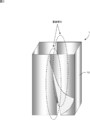
- 2 is a perspective view illustrating an overlapping portion of a covering portion 1.
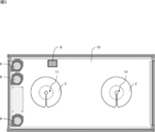
- FIG. 2 is a plan view illustrating an example of a canopy 10.
- FIG. 4A is a plan view showing the positional relationship between the lid 2 and the hole 11.
- FIG. 4B is a plan view showing the detailed shape of the lid 2.
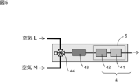
- FIG. 4 is a schematic diagram showing the arrangement of sensors 4.
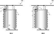
- FIG. 6A is a schematic diagram showing a state in which the sensor 4 is arranged in the system 100 as viewed from the X direction of FIG.
- FIG. 6B is a schematic diagram showing a state in which air M is sucked from another route in FIG. 6A.
- FIG. 7A is a schematic diagram illustrating the flow of air in the housing 5 when there is no air agitation unit 51.
- FIG. 7B is a schematic diagram illustrating the flow of air in the housing 5 when the air agitating unit 51 is provided. It is an example of the experimental result for demonstrating the significance of the air stirring part 51. FIG. It is an example of the experimental result for demonstrating the significance of the air stirring part 51.
- FIG. 7A is a schematic diagram illustrating the flow of air in the housing 5 when there is no air agitation unit 51.
- FIG. 7B is a schematic diagram illustrating the flow of air in the housing 5 when the air agitating unit 51 is provided. It is an example of the experimental result for demonstrating the significance of the air stirring part 51.
- System 100 A plant photosynthesis rate measuring system according to an embodiment of the present invention will be described with reference to FIGS. Hereinafter, the photosynthesis speed measurement system is referred to as a system 100.
- the system 100 measures the carbon dioxide concentration around the plant 9 and calculates the photosynthesis rate of the plant 9 from the carbon dioxide concentration.
- the system 100 according to the present embodiment can calculate the photosynthetic rate of the plant 9 in real time. Based on this calculation result, in order to increase the photosynthetic rate, it can be utilized for environmental adjustment such as adjusting the carbon dioxide concentration around the plant 9.
- the system 100 includes a covering unit 1 that covers the target plant 9, a housing 5, and a sensor 4 that alternately measures the carbon dioxide concentration inside and outside the covering unit 1. .
- the sensor 4 is provided in the housing 5.
- the sensor 4 includes a carbon dioxide sensor 41 and a water vapor sensor 42.
- the carbon dioxide sensor 41 measures the carbon dioxide concentration inside and outside the covering portion 1.
- the water vapor sensor 42 measures the water vapor concentration inside and outside the covering portion 1 in order to calculate the transpiration rate of the plant 9.
- an air agitating unit 51 that agitates the flow of air flowing into the housing 5 is provided inside the housing 5.
- the covering portion 1 includes a canopy 10 and a covering sheet 12.
- the canopy 10 is disposed above the target plant 9, and the covering sheet 12 is disposed so as to cover the periphery of the target plant 9.
- the material of the canopy 10 is not particularly limited, but is preferably transparent.
- the canopy 10 can be formed of a transparent material such as acrylic resin.
- the covering sheet 12 is comprised so that the overlap part which a some sheet
- the overlapping width of the overlapping portion is not particularly limited, but is preferably 1 cm or more, and more preferably 3 cm or more.
- the canopy 10 is provided with a hole 11, and the lid 2 includes an insertion portion 21 through which the cord 3 can be inserted, a slit 22 that leads from the outer edge of the lid 2 to the insertion portion 21, and Is provided.
- the lid 2 is disposed so that the insertion portion 21 overlaps the hole 11 and covers the hole 11 in plan view.
- a wire 33 is disposed above the canopy 10. Further, the cord 3 wound around the bobbin 34 attached to the wire 33 is inserted into the hole 11 of the canopy 10 through the insertion portion 21 provided in the lid 2 to hold the plant 9.
- the length of the cord 3 outside the bobbin 34 can be shortened by winding the bobbin 34.
- the length of the cord 3 outside the bobbin 34 can be increased.
- the lid 2 is provided for the purpose of closing the hole 11.
- the slit 22 includes a wide portion 23.
- the wide portion 23 is configured such that the width of the slit 22 increases toward the outer edge of the lid 2. Accordingly, it is easy to insert the cord 3 from the wide portion 23 and insert the cord 3 into the insertion portion 21 through the slit 22.
- the diameter r of the hole 11 and the diameter R of the lid 2 are preferably configured to satisfy the relationship “2 ⁇ R / r”.
- the hole 11 is provided in the canopy 10, the lid 2 is disposed so as to cover the hole 11, and the cord 3 is inserted into the insertion portion 21, whereby the cord 3 can be prevented from coming out of the hole 11.
- the value of R / r is preferably 2.1 to 3.0, and more preferably 2.4 to 2.6. Specifically, for example, 2.1, 2.2, 2.3, 2.4, 2.5, 2.6, 2.7, 2.8, 2.9, 3.0, where It may be within a range between any two of the exemplified numerical values.
- the shape of the lid 2 is not particularly limited as long as the insertion portion 21 overlaps the hole 11 and can be disposed so as to cover the hole 11 in a plan view.
- the diameter of the insertion portion 21 is 10 mm
- the width of the slit 22 is 3 mm
- the width of the wide portion 23 at the outer edge of the lid 2 is 10 mm
- the length of the wide portion 23 is 5 mm.
- a plurality of length adjustment cords 31 attached to the wires 33 are attached to the corners of the canopy 10.
- Each length adjustment cord 31 is provided with a length adjustment section 32.
- the canopy 10 is provided with an exhaust fan 6.
- the exhaust fan 6 penetrates the canopy 10 and exhausts the air in the cover 1 to the outside of the cover 1.
- the lower part of the covering sheet 12 is provided with a root gripping part 7 including the roots of the plant 9.
- the root gripping part 7 is composed of rock wool 71 and a slab 72.
- the root gripping portion 7 is not particularly limited as long as the growth of the plant 9 can be maintained, and soil, flooded water, or the like may be used.
- the canopy 10 is provided with a pyranometer 8.
- the sensor 4 is provided in the housing 5.
- the sensor 4 includes a carbon dioxide sensor 41 and a water vapor sensor 42.
- an air pump 43 and a three-way electromagnetic valve 44 for introducing air into the housing 5 are provided.
- the air to be introduced into the housing 5 is switched to either air L or air M by the three-way electromagnetic valve 44, and the air L or air M is introduced to the sensor 4 side by the air pump 43.
- the air M represents air that flows into the covering portion 1 (air outside the covering portion 1).
- Air L represents air that is exhausted outside the cover 1.
- the carbon dioxide sensor 41 is configured to be able to measure the concentration difference between the carbon dioxide concentration on the air inflow side and the air outlet side into the covering portion 1.
- the carbon dioxide sensor 41 is configured to be able to measure a concentration difference between carbon dioxide concentrations of air flowing into the covering portion 1 and air discharged outside the covering portion 1. That is, it can be said that the carbon dioxide sensor 41 is a sensor that detects a difference in the concentration of carbon dioxide.
- the carbon dioxide sensor 41 is not limited to this, and a sensor that directly detects the concentration of carbon dioxide can also be used.
- Air stirring unit 51 Next, the air stirring part 51 is demonstrated using FIG. As illustrated in FIG. 7B, in the present embodiment, an air agitating unit 51 that agitates the flow of air flowing in the housing 5 is provided inside the housing 5.
- the shape of the air stirring part 51 is not specifically limited, In the example of FIG. 7B, the air stirring part 51 of the some protrusion shape is employ
- the air stirring part 51 is provided in the inside of the housing
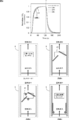
- FIG. 8 is a graph showing the results of an experiment conducted by providing a reference (control 1) and three comparison sections (flow paths A to C) for the response speed of the sensor 4 (carbon dioxide sensor 41). .
- FIG. 8 shows a standardized carbon dioxide concentration output from the sensor 4 (carbon dioxide sensor 41) when the carbon dioxide concentration of the air introduced into the housing 5 is changed from 380 ppm to 420 ppm. Yes.
- the carbon dioxide concentration of air introduced into the housing 5 at time 0 is changed from 380 ppm to 420 ppm
- the carbon dioxide concentration of air introduced into the housing 5 at time t1 is 420 ppm. To 380 ppm.
- the graph shown in FIG. 9 is a graph showing the result of an experiment conducted by providing a reference (control 2) and three comparison sections (channels A to C) for the response speed of the sensor 4 (carbon dioxide sensor 41). It is. Specifically, a reference (control 2) and a flow path D to a flow path F (corresponding to the air stirring unit 51) provided in the vicinity of the sensor 4 (carbon dioxide sensor 41) are prepared and introduced into the housing 5.
- FIG. 9 shows the standardized carbon dioxide concentration output from the sensor 4 (carbon dioxide sensor 41) when the carbon dioxide concentration in the air is changed from 380 ppm to 420 ppm.
- the carbon dioxide concentration of air introduced into the housing 5 at time 0 is changed from 380 ppm to 420 ppm
- the carbon dioxide concentration of air introduced into the housing 5 at time t1 is 420 ppm. To 380 ppm.
- the response time (0 ⁇ 100%) until the normalized carbon dioxide concentration reaches 1 is about 70. Seconds.
- the response time (0 ⁇ 100%) is about 60 seconds.
- the carbon dioxide concentration of air introduced into the housing 5 is changed from 420 ppm to 380 ppm until the normalized carbon dioxide concentration reaches zero.
- the response time (100 ⁇ 0%) was about 120 seconds, while the response time (100 ⁇ 0%) of channel A to channel C was about 80 seconds. From this result, it can be seen that the responsiveness of the sensor 4 (carbon dioxide sensor 41) is improved by providing the air stirring unit 51 in the vicinity of the sensor 4 (carbon dioxide sensor 41).
- FIGS. 8 and 9 show that the response speed of the sensor 4 (carbon dioxide sensor 41) is improved by providing the air agitation unit 51 in the vicinity of the sensor 4 (carbon dioxide sensor 41). It was.
- the photosynthetic rate A is calculated by the following formula, for example.
- the system 100 of the present invention can be implemented in the following modes.
- the photosynthesis rate of the plant 9 is calculated in real time, and the transition of the photosynthesis rate is visualized in real time using the information processing device.
- a predetermined number for example, three
- the exhaust fans 6 for example, three
- Two the exhaust fans 6 are stopped.
- an exhaust fan capable of adjusting the output is used.
Landscapes
- Life Sciences & Earth Sciences (AREA)
- Physics & Mathematics (AREA)
- Spectroscopy & Molecular Physics (AREA)
- Biodiversity & Conservation Biology (AREA)
- Botany (AREA)
- Ecology (AREA)
- Forests & Forestry (AREA)
- Environmental Sciences (AREA)
- Health & Medical Sciences (AREA)
- Chemical & Material Sciences (AREA)
- Analytical Chemistry (AREA)
- Biochemistry (AREA)
- General Health & Medical Sciences (AREA)
- General Physics & Mathematics (AREA)
- Immunology (AREA)
- Pathology (AREA)
- Cultivation Of Plants (AREA)
- Greenhouses (AREA)
- Investigating Or Analysing Materials By Optical Means (AREA)
Abstract
簡易な構成で植物の光合成速度を算出するために、二酸化炭素濃度を計測可能な光合成速度計測システムを提供する。 本発明によれば、植物の光合成速度計測システムであって、対象植物を被覆する被覆部と、筐体と、前記被覆部内外の二酸化炭素濃度を交互に計測するセンサと、を備え、前記センサは、前記筐体内に設けられ、前記筐体の内部に、前記筐体に流入する空気の流れを撹拌する空気撹拌部が設けられる、システムが提供される。
Description
本発明は、植物の光合成速度を計測可能な光合成速度計測システムに関する。
植物の光合成速度を計測するシステムが知られている。
特許文献1には、光合成サンプルを正確にかつより簡単に評価することが可能な評価システムが開示されている。
本発明は、簡易な構成で植物の光合成速度を算出するために、二酸化炭素濃度を計測可能な光合成速度計測システムを提供するものである。
以下、本発明の種々の実施形態を例示する。以下に示す実施形態は互いに組み合わせ可能である。
本発明によれば、植物の光合成速度計測システムであって、対象植物を被覆する被覆部と、筐体と、前記被覆部内外の二酸化炭素濃度を交互に計測するセンサと、を備え、前記センサは、前記筐体内に設けられ、前記筐体の内部に、前記筐体に流入する空気の流れを撹拌する空気撹拌部が設けられる、システムが提供される。
本発明によれば、対象植物を被覆する被覆部と、筐体と、被覆部内外の二酸化炭素濃度を交互に計測するセンサと、を備える光合成速度計測システムが提供される。具体的には、センサは、筐体内に設けられる。また、筐体の内部に、筐体に流入する空気の流れを撹拌する空気撹拌部が設けられる。空気撹拌部を設けることにより、空気の流れが撹拌され、センサと空気の接触が促進される。これにより、センサの応答速度が向上する。
以下、本発明の種々の実施形態を例示する。以下に示す実施形態は互いに組み合わせ可能である。
好ましくは、前記センサは、前記被覆部への空気の流入側と吹出側の二酸化炭素濃度の濃度差を計測可能に構成され、前記空気撹拌部は、前記被覆部への空気の流入側又は吹出側の空気の二酸化炭素の濃度の変化に起因する前記センサの応答速度を向上させるように設けられる。
好ましくは、前記空気撹拌部は、前記筐体の内部において前記センサと空気が接する面に対向するように設けられる。
好ましくは、前記被覆部は、天蓋及び被覆シートを備え、前記天蓋は、対象植物の上側に配置され、前記被覆シートは、対象植物の周囲を覆うように配置され、前記被覆シートは、複数のシートが被覆する重複部分を備えるように構成される。
好ましくは、蓋及びコードを備え、前記天蓋に孔が設けられ、前記蓋は、前記コードを挿通可能な挿通部と、前記蓋の外縁から前記挿通部に通じるスリットと、を備え、前記蓋は、平面視において、前記挿通部が前記孔と重なり、且つ、前記孔を覆うように配置され、前記コードは、前記挿通部を介して前記孔に挿通される。
好ましくは、前記スリットは、前記蓋の外縁に向けて前記スリットの幅が大きくなるように構成される。
好ましくは、前記孔の直径rと、前記蓋の直径Rは、「2<R/r」の関係を満たすように構成される。
好ましくは、前記天蓋に排気用ファンが設けられる。
好ましくは、前記空気撹拌部は、前記筐体の内部において前記センサと空気が接する面に対向するように設けられる。
好ましくは、前記被覆部は、天蓋及び被覆シートを備え、前記天蓋は、対象植物の上側に配置され、前記被覆シートは、対象植物の周囲を覆うように配置され、前記被覆シートは、複数のシートが被覆する重複部分を備えるように構成される。
好ましくは、蓋及びコードを備え、前記天蓋に孔が設けられ、前記蓋は、前記コードを挿通可能な挿通部と、前記蓋の外縁から前記挿通部に通じるスリットと、を備え、前記蓋は、平面視において、前記挿通部が前記孔と重なり、且つ、前記孔を覆うように配置され、前記コードは、前記挿通部を介して前記孔に挿通される。
好ましくは、前記スリットは、前記蓋の外縁に向けて前記スリットの幅が大きくなるように構成される。
好ましくは、前記孔の直径rと、前記蓋の直径Rは、「2<R/r」の関係を満たすように構成される。
好ましくは、前記天蓋に排気用ファンが設けられる。
以下、図面を用いて本発明の実施形態について説明する。以下に示す実施形態中で示した各種特徴事項は、互いに組み合わせ可能である。
1.システム100
図1~図7を用いて、本発明の一実施形態に係る植物の光合成速度計測システムについて説明する。以下、光合成速度計測システムをシステム100と称する。
図1~図7を用いて、本発明の一実施形態に係る植物の光合成速度計測システムについて説明する。以下、光合成速度計測システムをシステム100と称する。
システム100は、植物9の周辺の二酸化炭素濃度を測定し、二酸化炭素濃度から植物9の光合成速度を算出するものである。本実施形態に係るシステム100により、植物9の光合成速度をリアルタイムに算出することができる。この算出結果に基づいて、光合成速度を増大させるために、植物9周辺の二酸化炭素濃度を調節する等といった環境調節に活用することができる。
図1、図5、図6に示すように、システム100は、対象植物9を被覆する被覆部1と、筐体5と、被覆部1内外の二酸化炭素濃度を交互に計測するセンサ4を備える。図5に示すように、本実施形態では、筐体5内にセンサ4が設けられる。センサ4は、二酸化炭素センサ41及び水蒸気センサ42を備える。ここで、二酸化炭素センサ41は、被覆部1内外の二酸化炭素濃度を計測するものである。また、水蒸気センサ42は、植物9の蒸散速度を算出するために、被覆部1内外の水蒸気濃度を計測するものである。そして、図7Bに示すように、筐体5の内部に、筐体5に流入する空気の流れを撹拌する空気撹拌部51が設けられる。
また、図1、図3、図4に示すように、被覆部1は、天蓋10及び被覆シート12を備える。天蓋10は、対象植物9の上側に配置され、被覆シート12は、対象植物9の周囲を覆うように配置される。天蓋10の素材は特に限定されないが、透明であることが好ましい。例えば、アクリル樹脂等の透明素材により、天蓋10を形成することができる。また、図2に示すように、本実施形態では、被覆シート12は、複数のシートが被覆する重複部分を備えるように構成される。これは、主に複数の被覆シートの境目から被覆部1内に被覆部1外の空気が流入するのを防ぐ目的のものであるが、これに加えて、被覆部1により被覆された植物9の手入れを容易にするものである。すなわち、複数のシートが被覆する重複部分を備えるように被覆シート12を構成することにより、重複部分の被覆シート12をめくりあげ、被覆部1内に手を入れやすくすることにより、植物9の手入れを容易にするものである。重複部分の重複幅は特に限定されないが、1cm以上が好ましく、3cm以上がさらに好ましい。
図3及び図4に示すように、天蓋10には、孔11が設けられ、蓋2は、コード3を挿通可能な挿通部21と、蓋2の外縁から挿通部21に通じるスリット22と、を備える。蓋2は、平面視において、挿通部21が孔11と重なり、且つ、孔11を覆うように配置される。そして、図1に示すように、天蓋10の上方には、ワイヤー33が配設される。また、ワイヤー33に取り付けられたボビン34に巻かれたコード3が、蓋2に設けられた挿通部21を介して天蓋10の孔11に挿通され、植物9を保持する。本実施形態では、ボビン34を巻き取ることにより、ボビン34外のコード3の長さを短くすることができる。逆に、コード3をボビン34から引き出すことにより、ボビン34外のコード3の長さを長くすることができる。このように、ボビン34に巻きつけたコード3を被覆部1内に垂下させるために、天蓋10に孔11を設ける必要がある。しかし、被覆部1内の二酸化炭素濃度を計測するために、孔11を塞ぐ目的で蓋2を設けている。
図4Aに示すように、本実施形態では、スリット22は、幅広部23を備える。幅広部23は、蓋2の外縁に向けてスリット22の幅が大きくなるように構成される。これにより、幅広部23からコード3を差し込み、スリット22を通して挿通部21にコード3を挿通することが容易になる。
図4Aに示すように、孔11の直径rと、蓋2の直径Rは、「2<R/r」の関係を満たすように構成されることが好ましい。これにより、天蓋10に孔11を設け、孔11を覆うように蓋2を配置し、挿通部21にコード3を挿通することにより、コード3が孔11から抜けることを防止することができる。換言すると、蓋2が移動した場合でも、孔11が常に防がれた状態を維持する。R/rの値は、好ましくは、2.1~3.0、さらに好ましくは、2.4~2.6である。具体的には例えば、2.1、2.2、2.3、2.4、2.5、2.6、2.7、2.8、2.9、3.0であり、ここで例示した数値の何れか2つの間の範囲内であってもよい。
蓋2の形状は、平面視において、挿通部21が孔11と重なり、且つ、孔11を覆うように配置可能であれば特に限定されないが、例えば図4Bに示すように、蓋2の直径Rを220mm、挿通部21の直径を10mm、スリット22の幅を3mm、蓋2の外縁における幅広部23の幅を10mm、幅広部23の長さを5mmとすることができる。
また、図1に示すように、ワイヤー33に取り付けられた複数の長さ調節コード31が天蓋10の角部に取り付けられる。長さ調節コード31にはそれぞれ、長さ調節部32が設けられる。長さ調節部32を調整することにより、長さ調節コード31の長さを調整し、植物9の高さに合わせて被覆部1を適切に被覆することが可能になる。
図1及び図3に示すように、天蓋10に排気用ファン6が設けられる。排気用ファン6は、天蓋10を貫通しており、被覆部1内の空気を被覆部1外に排気するものである。そして、被覆シート12の下部には、植物9の根を含む根把持部7が設けられる。根把持部7は、ロックウール71及びスラブ72により構成される。ただし、根把持部7については、植物9の生育を維持することができれば特に限定されず、土壌や湛水等でも構わない。また、天蓋10には日射計8が設けられる。
2.センサ4
次に、図5及び図6を用いて、センサ4について説明する。図5に示すように、本実施形態では、筐体5内にセンサ4が設けられる。センサ4は、二酸化炭素センサ41及び水蒸気センサ42を備える。また、筐体5に空気を導入するためのエアポンプ43及び三方向電磁弁44が設けられる。三方向電磁弁44により、筐体5に導入する空気を空気L又は空気Mのいずれかに切り替え、エアポンプ43により空気L又は空気Mをセンサ4側に導入する。ここで、空気Mは、被覆部1内に流入する空気(被覆部1外の空気)を表す。また、空気Lは、被覆部1外に排気される空気を表す。
次に、図5及び図6を用いて、センサ4について説明する。図5に示すように、本実施形態では、筐体5内にセンサ4が設けられる。センサ4は、二酸化炭素センサ41及び水蒸気センサ42を備える。また、筐体5に空気を導入するためのエアポンプ43及び三方向電磁弁44が設けられる。三方向電磁弁44により、筐体5に導入する空気を空気L又は空気Mのいずれかに切り替え、エアポンプ43により空気L又は空気Mをセンサ4側に導入する。ここで、空気Mは、被覆部1内に流入する空気(被覆部1外の空気)を表す。また、空気Lは、被覆部1外に排気される空気を表す。
本実施形態では、二酸化炭素センサ41は、被覆部1内への空気の流入側と吹出側の二酸化炭素濃度の濃度差を計測可能に構成される。換言すると、二酸化炭素センサ41は、被覆部1内に流入する空気と被覆部1外に排出される空気の二酸化炭素濃度の濃度差を計測可能なように構成される。つまり、二酸化炭素センサ41は、二酸化炭素の濃度の差分を検出するセンサであるといえる。なお、二酸化炭素センサ41はこれに限定されず、二酸化炭素の濃度を直接検出するセンサを用いることもできる。
3.空気撹拌部51
次に、図7を用いて、空気撹拌部51について説明する。図7Bに示すように、本実施形態では、筐体5の内部に、筐体5内を流れる空気の流れを撹拌する空気撹拌部51が設けられる。空気撹拌部51の形状は特に限定されないが、図7Bの例では、複数の突起形状の空気撹拌部51を採用している。また、本実施形態では、空気撹拌部51は、筐体5の内部においてセンサ4(二酸化炭素センサ41)と空気が接する面(接触面S)に対向するように設けられる。これにより、空気の流れが乱され、空気とセンサ4(二酸化炭素センサ41)の接触が促進される。この結果、空気撹拌部51により、筐体5に導入する空気を、被覆部1に流入する空気から排出される空気(又は、被覆部1から排出する空気から流入する空気)に切り替えた際の二酸化炭素の濃度の変化に起因するセンサ4(二酸化炭素センサ41)の応答速度が向上する。
次に、図7を用いて、空気撹拌部51について説明する。図7Bに示すように、本実施形態では、筐体5の内部に、筐体5内を流れる空気の流れを撹拌する空気撹拌部51が設けられる。空気撹拌部51の形状は特に限定されないが、図7Bの例では、複数の突起形状の空気撹拌部51を採用している。また、本実施形態では、空気撹拌部51は、筐体5の内部においてセンサ4(二酸化炭素センサ41)と空気が接する面(接触面S)に対向するように設けられる。これにより、空気の流れが乱され、空気とセンサ4(二酸化炭素センサ41)の接触が促進される。この結果、空気撹拌部51により、筐体5に導入する空気を、被覆部1に流入する空気から排出される空気(又は、被覆部1から排出する空気から流入する空気)に切り替えた際の二酸化炭素の濃度の変化に起因するセンサ4(二酸化炭素センサ41)の応答速度が向上する。
一方、図7Aに示すように、空気撹拌部51を設けない場合、空気の流れが撹拌されず、空気とセンサ4(二酸化炭素センサ41)の接触が促進されない。
4.空気撹拌部51の意義
次に、図8及び図9を用いて、空気撹拌部51の意義について説明する。図8に示されるグラフは、センサ4(二酸化炭素センサ41)の応答速度について、基準(コントロール1)と3つの比較区(流路A~C)を設けて行った実験結果を表すグラフである。具体的には、センサ4(二酸化炭素センサ41)と空気が接する面(接触面S)に空気撹拌部51を有さない基準(コントロール1)と、センサ4(二酸化炭素センサ41)と空気が接する面(接触面S)に空気撹拌部51を設けた流路A~流路B、さらには、センサ4(二酸化炭素センサ41)から離れた箇所に空気撹拌部51を設けた流路Cを準備した。筐体5内に導入する空気の二酸化炭素濃度を380ppmから420ppmに変化させた場合における、センサ4(二酸化炭素センサ41)から出力される二酸化炭素濃度を規格化したものが図8に示されている。図8の例では、時刻0の時点で筐体5内に導入する空気の二酸化炭素濃度を380ppmから420ppmに変化させ、時刻t1の時点で筐体5内に導入する空気の二酸化炭素濃度を420ppmから380ppmに変化させた。
次に、図8及び図9を用いて、空気撹拌部51の意義について説明する。図8に示されるグラフは、センサ4(二酸化炭素センサ41)の応答速度について、基準(コントロール1)と3つの比較区(流路A~C)を設けて行った実験結果を表すグラフである。具体的には、センサ4(二酸化炭素センサ41)と空気が接する面(接触面S)に空気撹拌部51を有さない基準(コントロール1)と、センサ4(二酸化炭素センサ41)と空気が接する面(接触面S)に空気撹拌部51を設けた流路A~流路B、さらには、センサ4(二酸化炭素センサ41)から離れた箇所に空気撹拌部51を設けた流路Cを準備した。筐体5内に導入する空気の二酸化炭素濃度を380ppmから420ppmに変化させた場合における、センサ4(二酸化炭素センサ41)から出力される二酸化炭素濃度を規格化したものが図8に示されている。図8の例では、時刻0の時点で筐体5内に導入する空気の二酸化炭素濃度を380ppmから420ppmに変化させ、時刻t1の時点で筐体5内に導入する空気の二酸化炭素濃度を420ppmから380ppmに変化させた。
図8に示されるグラフから明らかなように、基準(コントロール1)と流路Cの場合(グラフ中のC1と流路C)、正規化した二酸化炭素濃度が0.9に到達するまでの応答時間(0→90%)は46秒である。一方、流路A及び流路Bの場合、応答時間(0→90%)は37秒であり。また、流入空気の二酸化炭濃度を420ppmから380ppmに変化させた場合の応答時間(0→90%)も同様である。この結果より、センサ4(二酸化炭素センサ41)と空気が接する面(接触面S)に空気撹拌部51を設けることにより、センサ4(二酸化炭素センサ41)の応答性が向上することが分かる。
また、図9に示されるグラフは、センサ4(二酸化炭素センサ41)の応答速度について、基準(コントロール2)と3つの比較区(流路A~C)を設けて行った実験結果を表すグラフである。具体的には、基準(コントロール2)と、センサ4(二酸化炭素センサ41)付近に設けた流路D~流路F(空気撹拌部51に相当)を準備し、筐体5内に導入する空気の二酸化炭素濃度を380ppmから420ppmに変化させた場合における、センサ4(二酸化炭素センサ41)から出力される二酸化炭素濃度を規格化したものが図9に示されている。図9の例では、時刻0の時点で筐体5内に導入する空気の二酸化炭素濃度を380ppmから420ppmに変化させ、時刻t1の時点で筐体5内に導入する空気の二酸化炭素濃度を420ppmから380ppmに変化させた。
図9に示されるグラフから明らかなように、基準(コントロール2)の場合(グラフ中のC2)、正規化した二酸化炭素濃度が1に到達するまでの応答時間(0→100%)は約70秒である。一方、流路A~流路Cの場合、応答時間(0→100%)は約60秒である。また、基準(コントロール2)の場合(グラフ中のC2)、筐体5内に導入する空気の二酸化炭素濃度を420ppmから380ppmに変化させてから正規化した二酸化炭素濃度が0に到達するまでの応答時間(100→0%)は約120秒であり、一方、流路A~流路Cの応答時間(100→0%)は約80秒であった。この結果より、センサ4(二酸化炭素センサ41)の付近に空気撹拌部51を設けることにより、センサ4(二酸化炭素センサ41)の応答性が向上することが分かる。
このように、図8及び図9の結果より、センサ4(二酸化炭素センサ41)付近に空気撹拌部51を設けることにより、センサ4(二酸化炭素センサ41)の応答速度が向上することが示された。
4.光合成速度の算出
次に、センサ4(二酸化炭素センサ41)を用いて計測した二酸化炭素濃度を用いて、植物9の光合成速度を算出する方法について説明する。光合成速度Aは、例えば以下の数式で算出される。
次に、センサ4(二酸化炭素センサ41)を用いて計測した二酸化炭素濃度を用いて、植物9の光合成速度を算出する方法について説明する。光合成速度Aは、例えば以下の数式で算出される。
<数式>A=F(Cin―Cout)
A:光合成速度
F:排気用ファン6による排気量(mol min-1)
Cin:被覆部1に流入する空気の二酸化炭素濃度(μmol mol-1)
Cout:被覆部1から排出される空気の二酸化炭素濃度(μmol mol-1)
A:光合成速度
F:排気用ファン6による排気量(mol min-1)
Cin:被覆部1に流入する空気の二酸化炭素濃度(μmol mol-1)
Cout:被覆部1から排出される空気の二酸化炭素濃度(μmol mol-1)
これにより、センサ4(二酸化炭素センサ41)で計測した二酸化炭素濃度に基づいて、植物9の光合成速度を算出することが可能になる。
5.その他
本発明のシステム100は、以下の態様でも実施可能である。
・植物9の光合成速度をリアルタイムで算出し、情報処理装置を用いて光合成速度の推移をリアルタイムに可視化する。
・太陽光が弱く、被覆部1に流入する空気と被覆部1から排出される空気の二酸化炭素濃度差が小さくなると、複数(例:3個)の排気用ファン6のうち、所定数(例:2個)の排気用ファン6を停止する。
・排気用ファン6を複数設けることに代えて、出力調整可能な排気用ファンを用いる。
本発明のシステム100は、以下の態様でも実施可能である。
・植物9の光合成速度をリアルタイムで算出し、情報処理装置を用いて光合成速度の推移をリアルタイムに可視化する。
・太陽光が弱く、被覆部1に流入する空気と被覆部1から排出される空気の二酸化炭素濃度差が小さくなると、複数(例:3個)の排気用ファン6のうち、所定数(例:2個)の排気用ファン6を停止する。
・排気用ファン6を複数設けることに代えて、出力調整可能な排気用ファンを用いる。
1:被覆部、2:蓋、3:コード、4:センサ、5:筐体、6:排気用ファン、7:根把持部、8:日射計、9:植物、10:天蓋、11:孔、12:被覆シート、21:挿通部、22:スリット、23:幅広部、31:調節コード、32:調節部、33:ワイヤー、34:ボビン、41:二酸化炭素センサ、42:水蒸気センサ、43:エアポンプ、44:三方向電磁弁、51:空気撹拌部、71:ロックウール、72:スラブ、100:システム、S:接触面
Claims (8)
- 植物の光合成速度計測システムであって、
対象植物を被覆する被覆部と、
筐体と、
前記被覆部内外の二酸化炭素濃度を交互に計測するセンサと、
を備え、
前記センサは、前記筐体内に設けられ、
前記筐体の内部に、前記筐体に流入する空気の流れを撹拌する空気撹拌部が設けられる、
システム。 - 前記センサは、前記被覆部への空気の流入側と吹出側の二酸化炭素濃度の濃度差を計測可能に構成され、
前記空気撹拌部は、前記被覆部への空気の流入側又は吹出側の空気の二酸化炭素の濃度の変化に起因する前記センサの応答速度を向上させるように設けられる、
請求項1に記載のシステム。 - 前記空気撹拌部は、前記筐体の内部において前記センサと空気が接する面に対向するように設けられる、
請求項1又は請求項2に記載のシステム。 - 前記被覆部は、天蓋及び被覆シートを備え、
前記天蓋は、対象植物の上側に配置され、
前記被覆シートは、対象植物の周囲を覆うように配置され、
前記被覆シートは、複数のシートが被覆する重複部分を備えるように構成される、
請求項1~請求項3の何れか1つに記載のシステム。 - 蓋及びコードを備え、
前記天蓋に孔が設けられ、
前記蓋は、前記コードを挿通可能な挿通部と、前記蓋の外縁から前記挿通部に通じるスリットと、を備え、
前記蓋は、平面視において、前記挿通部が前記孔と重なり、且つ、前記孔を覆うように配置され、
前記コードは、前記挿通部を介して前記孔に挿通される、
請求項4に記載のシステム。 - 前記スリットは、前記蓋の外縁に向けて前記スリットの幅が大きくなるように構成される、
請求項5に記載のシステム。 - 前記孔の直径rと、前記蓋の直径Rは、「2<R/r」の関係を満たすように構成される、
請求項5又は請求項6に記載のシステム。 - 前記天蓋に排気用ファンが設けられる、
請求項4~請求項7の何れか1つに記載のシステム。
Priority Applications (2)
| Application Number | Priority Date | Filing Date | Title |
|---|---|---|---|
| EP19778024.0A EP3777516A4 (en) | 2018-03-28 | 2019-03-22 | SYSTEM FOR MEASURING THE PHOTOSYNTHESIS RATE |
| US17/041,154 US20210007288A1 (en) | 2018-03-28 | 2019-03-22 | Photosynthesis rate measurement system |
Applications Claiming Priority (2)
| Application Number | Priority Date | Filing Date | Title |
|---|---|---|---|
| JP2018-062412 | 2018-03-28 | ||
| JP2018062412A JP7181518B2 (ja) | 2018-03-28 | 2018-03-28 | 光合成速度計測システム |
Publications (1)
| Publication Number | Publication Date |
|---|---|
| WO2019188848A1 true WO2019188848A1 (ja) | 2019-10-03 |
Family
ID=68061787
Family Applications (1)
| Application Number | Title | Priority Date | Filing Date |
|---|---|---|---|
| PCT/JP2019/012260 Ceased WO2019188848A1 (ja) | 2018-03-28 | 2019-03-22 | 光合成速度計測システム |
Country Status (4)
| Country | Link |
|---|---|
| US (1) | US20210007288A1 (ja) |
| EP (1) | EP3777516A4 (ja) |
| JP (1) | JP7181518B2 (ja) |
| WO (1) | WO2019188848A1 (ja) |
Cited By (3)
| Publication number | Priority date | Publication date | Assignee | Title |
|---|---|---|---|---|
| JP2021069353A (ja) * | 2019-11-01 | 2021-05-06 | オムロン株式会社 | 植物生体センサ |
| CN112986246A (zh) * | 2021-04-26 | 2021-06-18 | 西南大学 | 自然光照植物群体气体交换检测箱及检测系统 |
| CN113093620A (zh) * | 2021-04-07 | 2021-07-09 | 安徽农业大学 | 一种分布式光合速率监测系统 |
Families Citing this family (3)
| Publication number | Priority date | Publication date | Assignee | Title |
|---|---|---|---|---|
| JP7525988B2 (ja) * | 2019-09-03 | 2024-07-31 | 株式会社スクウェア・エニックス | ビデオゲーム処理プログラム、及びビデオゲーム処理システム |
| JP7560114B2 (ja) * | 2021-02-10 | 2024-10-02 | 国立大学法人高知大学 | 光合成に関する学習データ作成装置、機械学習装置、推定装置、方法およびプログラム |
| CN121038596A (zh) | 2023-01-31 | 2025-11-28 | 国立大学法人广岛大学 | 生物信息测定器和生物信息的测定方法 |
Citations (7)
| Publication number | Priority date | Publication date | Assignee | Title |
|---|---|---|---|---|
| JPS56157956U (ja) * | 1980-04-21 | 1981-11-25 | ||
| JPH07113775A (ja) * | 1993-10-18 | 1995-05-02 | Toyota Motor Corp | アルコール濃度検出装置 |
| JPH11125034A (ja) * | 1997-10-22 | 1999-05-11 | Katsuko Kawashima | 自立式簡易構築体 |
| JP2007274908A (ja) * | 2006-04-03 | 2007-10-25 | Japan International Research Center For Agricultural Services | バッファーチャンバー方式ガス収支測定装置 |
| US20140026474A1 (en) * | 2012-07-25 | 2014-01-30 | Charles J. Kulas | Automated grow system |
| JP2014226064A (ja) * | 2013-05-21 | 2014-12-08 | パイオニア株式会社 | 発光制御装置、発光制御方法、及びプログラム |
| JP2017044531A (ja) | 2015-08-25 | 2017-03-02 | 浜松ホトニクス株式会社 | 光合成サンプルの評価システム、光合成サンプルの評価方法、および光合成サンプルの評価プログラム |
Family Cites Families (8)
| Publication number | Priority date | Publication date | Assignee | Title |
|---|---|---|---|---|
| DE60023005T2 (de) * | 1999-06-17 | 2006-07-20 | Smiths Detection Inc., Pasadena | Vielfach-sensor-system und -gerät |
| CA2828602A1 (en) * | 2010-03-16 | 2011-09-22 | Martin Mittelmark | Plant air purification enclosure apparatus and method |
| US20120181432A1 (en) * | 2011-01-13 | 2012-07-19 | Li-Cor, Inc. | Off-set compensation technique for dual analyzer gas exchange systems |
| US20150007498A1 (en) * | 2013-07-01 | 2015-01-08 | Joshua Hensley | Hydroponic system |
| US9678050B2 (en) * | 2014-07-30 | 2017-06-13 | Li-Cor, Inc. | Multi-functional piezo actuated flow controller |
| DE202015100160U1 (de) * | 2015-01-14 | 2016-04-15 | B+M Textil Gmbh & Co. Kg | Saat- und/oder Pflanzsystem |
| CA2981275C (en) * | 2016-10-26 | 2021-09-21 | Biochambers Incorporated | Whole plant gas exchange chamber using pressurization and ventilation of separated canopy and root zones |
| US10729080B2 (en) * | 2017-05-05 | 2020-08-04 | Benjamin Jon Staffeldt | Vertical aeroponic growing apparatus |
-
2018
- 2018-03-28 JP JP2018062412A patent/JP7181518B2/ja active Active
-
2019
- 2019-03-22 EP EP19778024.0A patent/EP3777516A4/en active Pending
- 2019-03-22 WO PCT/JP2019/012260 patent/WO2019188848A1/ja not_active Ceased
- 2019-03-22 US US17/041,154 patent/US20210007288A1/en not_active Abandoned
Patent Citations (7)
| Publication number | Priority date | Publication date | Assignee | Title |
|---|---|---|---|---|
| JPS56157956U (ja) * | 1980-04-21 | 1981-11-25 | ||
| JPH07113775A (ja) * | 1993-10-18 | 1995-05-02 | Toyota Motor Corp | アルコール濃度検出装置 |
| JPH11125034A (ja) * | 1997-10-22 | 1999-05-11 | Katsuko Kawashima | 自立式簡易構築体 |
| JP2007274908A (ja) * | 2006-04-03 | 2007-10-25 | Japan International Research Center For Agricultural Services | バッファーチャンバー方式ガス収支測定装置 |
| US20140026474A1 (en) * | 2012-07-25 | 2014-01-30 | Charles J. Kulas | Automated grow system |
| JP2014226064A (ja) * | 2013-05-21 | 2014-12-08 | パイオニア株式会社 | 発光制御装置、発光制御方法、及びプログラム |
| JP2017044531A (ja) | 2015-08-25 | 2017-03-02 | 浜松ホトニクス株式会社 | 光合成サンプルの評価システム、光合成サンプルの評価方法、および光合成サンプルの評価プログラム |
Non-Patent Citations (1)
| Title |
|---|
| See also references of EP3777516A4 |
Cited By (6)
| Publication number | Priority date | Publication date | Assignee | Title |
|---|---|---|---|---|
| JP2021069353A (ja) * | 2019-11-01 | 2021-05-06 | オムロン株式会社 | 植物生体センサ |
| WO2021085533A1 (ja) * | 2019-11-01 | 2021-05-06 | オムロン株式会社 | 植物生体センサ |
| JP7467887B2 (ja) | 2019-11-01 | 2024-04-16 | オムロン株式会社 | 植物生体センサ |
| US12163943B2 (en) | 2019-11-01 | 2024-12-10 | Omron Corporation | Plant biosensor |
| CN113093620A (zh) * | 2021-04-07 | 2021-07-09 | 安徽农业大学 | 一种分布式光合速率监测系统 |
| CN112986246A (zh) * | 2021-04-26 | 2021-06-18 | 西南大学 | 自然光照植物群体气体交换检测箱及检测系统 |
Also Published As
| Publication number | Publication date |
|---|---|
| JP7181518B2 (ja) | 2022-12-01 |
| US20210007288A1 (en) | 2021-01-14 |
| EP3777516A1 (en) | 2021-02-17 |
| EP3777516A4 (en) | 2021-04-28 |
| JP2019170247A (ja) | 2019-10-10 |
Similar Documents
| Publication | Publication Date | Title |
|---|---|---|
| WO2019188848A1 (ja) | 光合成速度計測システム | |
| US9381457B2 (en) | Air treatment device with a detachable sensor module | |
| CN104244766B (zh) | 干发器和手持式器具 | |
| EP2941636B1 (en) | System and method for sensing ammonia in a fluid | |
| EP1842952B1 (en) | Sensor device for a household appliance | |
| JP2016527496A (ja) | 磁気流量計 | |
| US20030130815A1 (en) | Air flow sensing and control for animal confinement system | |
| JP6082506B1 (ja) | 鶏舎の換気方法 | |
| US20180187694A1 (en) | Centrifugal fan and ventilation fan | |
| JP2015014433A (ja) | ファンフィルターユニット | |
| SE1350052A1 (sv) | Förfarande för styrning av en rotationshastighetsreglerad lågtrycks centrifugalfläkt | |
| KR101706769B1 (ko) | 건축물 실내공기 순환 장치 | |
| CN207557192U (zh) | 具有一体式传感器防护罩的环境检测装置 | |
| WO2018051531A1 (ja) | 水位温度測定装置 | |
| JPS61210912A (ja) | 空気流量測定装置 | |
| JP2017063635A (ja) | 農業用ハウス | |
| Albright | Controlling greenhouse ventilation inlets by pressure difference | |
| TR200803916T1 (tr) | Makara ve makara malzemesinin özelliklerini tanımlamak için cihaz | |
| US20230270351A1 (en) | Measuring apparatus | |
| JP7805658B2 (ja) | 鶏舎換気システム及び鶏舎換気方法 | |
| CN207556561U (zh) | 用于环境检测装置的一体式传感器防护罩 | |
| RU2005120924A (ru) | Способ регулирования линейной плотности волокнистого настила и ленты на кардочесальной машине | |
| FI126871B (fi) | Tuloilmalaitteen säätömenetelmä | |
| GB2535013A (en) | Ventilation system with measuring system | |
| KR101829689B1 (ko) | 돈사의 환기장치 및 시스템 |
Legal Events
| Date | Code | Title | Description |
|---|---|---|---|
| 121 | Ep: the epo has been informed by wipo that ep was designated in this application |
Ref document number: 19778024 Country of ref document: EP Kind code of ref document: A1 |
|
| NENP | Non-entry into the national phase |
Ref country code: DE |
|
| ENP | Entry into the national phase |
Ref document number: 2019778024 Country of ref document: EP Effective date: 20201028 |