WO2019189103A1 - 操舵機能付ハブユニット、操舵システムおよび車両 - Google Patents
操舵機能付ハブユニット、操舵システムおよび車両 Download PDFInfo
- Publication number
- WO2019189103A1 WO2019189103A1 PCT/JP2019/012728 JP2019012728W WO2019189103A1 WO 2019189103 A1 WO2019189103 A1 WO 2019189103A1 JP 2019012728 W JP2019012728 W JP 2019012728W WO 2019189103 A1 WO2019189103 A1 WO 2019189103A1
- Authority
- WO
- WIPO (PCT)
- Prior art keywords
- steering
- hub unit
- unit
- wheel
- hub
- Prior art date
- Legal status (The legal status is an assumption and is not a legal conclusion. Google has not performed a legal analysis and makes no representation as to the accuracy of the status listed.)
- Ceased
Links
Images


Classifications
-
- B—PERFORMING OPERATIONS; TRANSPORTING
- B60—VEHICLES IN GENERAL
- B60B—VEHICLE WHEELS; CASTORS; AXLES FOR WHEELS OR CASTORS; INCREASING WHEEL ADHESION
- B60B35/00—Axle units; Parts thereof ; Arrangements for lubrication of axles
- B60B35/003—Steerable axles
-
- B—PERFORMING OPERATIONS; TRANSPORTING
- B62—LAND VEHICLES FOR TRAVELLING OTHERWISE THAN ON RAILS
- B62D—MOTOR VEHICLES; TRAILERS
- B62D6/00—Arrangements for automatically controlling steering depending on driving conditions sensed and responded to, e.g. control circuits
- B62D6/002—Arrangements for automatically controlling steering depending on driving conditions sensed and responded to, e.g. control circuits computing target steering angles for front or rear wheels
-
- B—PERFORMING OPERATIONS; TRANSPORTING
- B60—VEHICLES IN GENERAL
- B60B—VEHICLE WHEELS; CASTORS; AXLES FOR WHEELS OR CASTORS; INCREASING WHEEL ADHESION
- B60B35/00—Axle units; Parts thereof ; Arrangements for lubrication of axles
- B60B35/12—Torque-transmitting axles
- B60B35/18—Arrangement of bearings
-
- B—PERFORMING OPERATIONS; TRANSPORTING
- B62—LAND VEHICLES FOR TRAVELLING OTHERWISE THAN ON RAILS
- B62D—MOTOR VEHICLES; TRAILERS
- B62D5/00—Power-assisted or power-driven steering
- B62D5/04—Power-assisted or power-driven steering electrical, e.g. using an electric servo-motor connected to, or forming part of, the steering gear
- B62D5/0418—Electric motor acting on road wheel carriers
-
- F—MECHANICAL ENGINEERING; LIGHTING; HEATING; WEAPONS; BLASTING
- F16—ENGINEERING ELEMENTS AND UNITS; GENERAL MEASURES FOR PRODUCING AND MAINTAINING EFFECTIVE FUNCTIONING OF MACHINES OR INSTALLATIONS; THERMAL INSULATION IN GENERAL
- F16C—SHAFTS; FLEXIBLE SHAFTS; ELEMENTS OR CRANKSHAFT MECHANISMS; ROTARY BODIES OTHER THAN GEARING ELEMENTS; BEARINGS
- F16C19/00—Bearings with rolling contact, for exclusively rotary movement
- F16C19/22—Bearings with rolling contact, for exclusively rotary movement with bearing rollers essentially of the same size in one or more circular rows, e.g. needle bearings
- F16C19/34—Bearings with rolling contact, for exclusively rotary movement with bearing rollers essentially of the same size in one or more circular rows, e.g. needle bearings for both radial and axial load
- F16C19/36—Bearings with rolling contact, for exclusively rotary movement with bearing rollers essentially of the same size in one or more circular rows, e.g. needle bearings for both radial and axial load with a single row of rollers
- F16C19/364—Bearings with rolling contact, for exclusively rotary movement with bearing rollers essentially of the same size in one or more circular rows, e.g. needle bearings for both radial and axial load with a single row of rollers with tapered rollers, i.e. rollers having essentially the shape of a truncated cone
-
- F—MECHANICAL ENGINEERING; LIGHTING; HEATING; WEAPONS; BLASTING
- F16—ENGINEERING ELEMENTS AND UNITS; GENERAL MEASURES FOR PRODUCING AND MAINTAINING EFFECTIVE FUNCTIONING OF MACHINES OR INSTALLATIONS; THERMAL INSULATION IN GENERAL
- F16C—SHAFTS; FLEXIBLE SHAFTS; ELEMENTS OR CRANKSHAFT MECHANISMS; ROTARY BODIES OTHER THAN GEARING ELEMENTS; BEARINGS
- F16C25/00—Bearings for exclusively rotary movement adjustable for wear or play
- F16C25/06—Ball or roller bearings
-
- B—PERFORMING OPERATIONS; TRANSPORTING
- B60—VEHICLES IN GENERAL
- B60B—VEHICLE WHEELS; CASTORS; AXLES FOR WHEELS OR CASTORS; INCREASING WHEEL ADHESION
- B60B35/00—Axle units; Parts thereof ; Arrangements for lubrication of axles
- B60B35/12—Torque-transmitting axles
- B60B35/14—Torque-transmitting axles composite or split, e.g. half- axles; Couplings between axle parts or sections
-
- B—PERFORMING OPERATIONS; TRANSPORTING
- B60—VEHICLES IN GENERAL
- B60G—VEHICLE SUSPENSION ARRANGEMENTS
- B60G2206/00—Indexing codes related to the manufacturing of suspensions: constructional features, the materials used, procedures or tools
- B60G2206/01—Constructional features of suspension elements, e.g. arms, dampers, springs
- B60G2206/50—Constructional features of wheel supports or knuckles, e.g. steering knuckles, spindle attachments
-
- B—PERFORMING OPERATIONS; TRANSPORTING
- B60—VEHICLES IN GENERAL
- B60G—VEHICLE SUSPENSION ARRANGEMENTS
- B60G2500/00—Indexing codes relating to the regulated action or device
- B60G2500/40—Steering
-
- B—PERFORMING OPERATIONS; TRANSPORTING
- B60—VEHICLES IN GENERAL
- B60G—VEHICLE SUSPENSION ARRANGEMENTS
- B60G2800/00—Indexing codes relating to the type of movement or to the condition of the vehicle and to the end result to be achieved by the control action
- B60G2800/90—System Controller type
- B60G2800/96—ASC - Assisted or power Steering control
- B60G2800/963—Steer-by-wire
-
- B—PERFORMING OPERATIONS; TRANSPORTING
- B62—LAND VEHICLES FOR TRAVELLING OTHERWISE THAN ON RAILS
- B62D—MOTOR VEHICLES; TRAILERS
- B62D7/00—Steering linkage; Stub axles or their mountings
- B62D7/06—Steering linkage; Stub axles or their mountings for individually-pivoted wheels, e.g. on king-pins
-
- B—PERFORMING OPERATIONS; TRANSPORTING
- B62—LAND VEHICLES FOR TRAVELLING OTHERWISE THAN ON RAILS
- B62D—MOTOR VEHICLES; TRAILERS
- B62D7/00—Steering linkage; Stub axles or their mountings
- B62D7/18—Steering knuckles; King pins
-
- F—MECHANICAL ENGINEERING; LIGHTING; HEATING; WEAPONS; BLASTING
- F16—ENGINEERING ELEMENTS AND UNITS; GENERAL MEASURES FOR PRODUCING AND MAINTAINING EFFECTIVE FUNCTIONING OF MACHINES OR INSTALLATIONS; THERMAL INSULATION IN GENERAL
- F16C—SHAFTS; FLEXIBLE SHAFTS; ELEMENTS OR CRANKSHAFT MECHANISMS; ROTARY BODIES OTHER THAN GEARING ELEMENTS; BEARINGS
- F16C19/00—Bearings with rolling contact, for exclusively rotary movement
- F16C19/22—Bearings with rolling contact, for exclusively rotary movement with bearing rollers essentially of the same size in one or more circular rows, e.g. needle bearings
- F16C19/34—Bearings with rolling contact, for exclusively rotary movement with bearing rollers essentially of the same size in one or more circular rows, e.g. needle bearings for both radial and axial load
- F16C19/38—Bearings with rolling contact, for exclusively rotary movement with bearing rollers essentially of the same size in one or more circular rows, e.g. needle bearings for both radial and axial load with two or more rows of rollers
- F16C19/381—Bearings with rolling contact, for exclusively rotary movement with bearing rollers essentially of the same size in one or more circular rows, e.g. needle bearings for both radial and axial load with two or more rows of rollers with at least one row for radial load in combination with at least one row for axial load
-
- F—MECHANICAL ENGINEERING; LIGHTING; HEATING; WEAPONS; BLASTING
- F16—ENGINEERING ELEMENTS AND UNITS; GENERAL MEASURES FOR PRODUCING AND MAINTAINING EFFECTIVE FUNCTIONING OF MACHINES OR INSTALLATIONS; THERMAL INSULATION IN GENERAL
- F16C—SHAFTS; FLEXIBLE SHAFTS; ELEMENTS OR CRANKSHAFT MECHANISMS; ROTARY BODIES OTHER THAN GEARING ELEMENTS; BEARINGS
- F16C23/00—Bearings for exclusively rotary movement adjustable for aligning or positioning
- F16C23/06—Ball or roller bearings
-
- F—MECHANICAL ENGINEERING; LIGHTING; HEATING; WEAPONS; BLASTING
- F16—ENGINEERING ELEMENTS AND UNITS; GENERAL MEASURES FOR PRODUCING AND MAINTAINING EFFECTIVE FUNCTIONING OF MACHINES OR INSTALLATIONS; THERMAL INSULATION IN GENERAL
- F16C—SHAFTS; FLEXIBLE SHAFTS; ELEMENTS OR CRANKSHAFT MECHANISMS; ROTARY BODIES OTHER THAN GEARING ELEMENTS; BEARINGS
- F16C2326/00—Articles relating to transporting
- F16C2326/01—Parts of vehicles in general
- F16C2326/02—Wheel hubs or castors
-
- F—MECHANICAL ENGINEERING; LIGHTING; HEATING; WEAPONS; BLASTING
- F16—ENGINEERING ELEMENTS AND UNITS; GENERAL MEASURES FOR PRODUCING AND MAINTAINING EFFECTIVE FUNCTIONING OF MACHINES OR INSTALLATIONS; THERMAL INSULATION IN GENERAL
- F16C—SHAFTS; FLEXIBLE SHAFTS; ELEMENTS OR CRANKSHAFT MECHANISMS; ROTARY BODIES OTHER THAN GEARING ELEMENTS; BEARINGS
- F16C2326/00—Articles relating to transporting
- F16C2326/20—Land vehicles
- F16C2326/24—Steering systems, e.g. steering rods or columns
Definitions
- the present invention relates to a vehicle equipped with a hub unit with a steering function, a steering system, and a hub unit with a steering function, and relates to a technique for improving fuel efficiency, stabilizing vehicle running performance and improving reliability.
- the vehicle geometry includes (1) “Parallel geometry” where the left and right wheels have the same turning angle, and (2) The turning inner wheel angle is turned larger than the turning outer wheel angle in order to make the turning center one place. Ackermann geometry is known.
- Ackermann geometry is a difference in rudder angle between the left and right wheels so that each wheel turns around a common point in order to smoothly turn the wheels when turning at low speeds where the centrifugal force acting on the vehicle can be ignored. Is set. However, in high-speed turning where the centrifugal force cannot be ignored, it is desirable that the wheels generate a cornering force in a direction that balances with the centrifugal force. Therefore, the parallel geometry is preferable to the Ackermann geometry.
- a general vehicle steering device is mechanically connected to a wheel, generally only a single fixed steering geometry can be taken, and an intermediate between the Ackermann geometry and the parallel geometry. Often set to static geometry. However, in this case, the difference in steering angle between the left and right wheels is insufficient in the low speed range, the steering angle of the outer wheel is excessive, and the steering angle of the inner wheel is excessive in the high speed range. If there is an unnecessary bias in the lateral force distribution of the inner and outer wheels in this way, it will cause fuel consumption deterioration due to worsening of running resistance and premature wear of the wheels, and the smoothness of cornering due to the inefficient use of the inner and outer wheels. There is a problem that is damaged.
- Patent Document 1 A steer-by-wire system (apparatus) represented by Patent Document 1 and the like includes a steering angle sensor for detecting a steering angle of a steering wheel and a torque sensor for detecting a steering reaction force actually applied to the steering shaft. These sensor signals are used to operate the actuator of the steering device, and the left and right wheels are steered by one steering device. In this case, a large motor is incorporated in the steering device disposed in the front portion of the chassis, and the entire system becomes large. The front part of the chassis has many other mechanisms such as engines and transmissions, and space is limited.
- Patent Document 2 The steering system operates a steering actuator that can independently steer each wheel of a front wheel or a rear wheel system, but this steering actuator is fixed to a chassis, and it is difficult to secure a space as in Patent Document 1.
- the wheel angle can be freely controlled independently according to the driving conditions, but the steering actuator is fixed to the chassis, and the length of the tie rod connecting the steering actuator and the wheel is Since it is constant, the wheel angle changes greatly in a situation where the vehicle sinks into the tire, such as during cornering, or in a situation where it rises, and it is difficult to adjust to a predetermined angle.
- Patent Document 3 Since the hub bearing is cantilevered with respect to the steered shaft, the rigidity is lowered, and the steering geometry may be changed by the traveling G. Further, when a reduction gear is provided on the steered shaft, the size of the entire mechanism including the motor increases. When the size of the entire mechanism is increased, it is difficult to arrange the entire mechanism on the inner periphery of the wheel. Moreover, when a reduction gear with a large reduction ratio is provided, the responsiveness decreases.
- the conventional mechanism having a steering function for each wheel can reduce the space required for the steering device in the front portion of the chassis, but is intended to change the toe angle or the camber angle of the wheel in the vehicle. For this reason, a plurality of motors and speed reduction mechanisms are required, resulting in a complicated configuration. Moreover, it is difficult to ensure rigidity, and it is necessary to increase the size and weight in order to ensure rigidity. Further, when the kingpin axis and the steered axis coincide with each other, since the component parts are arranged behind the hub unit (vehicle body side), the overall size increases and becomes heavy.
- Patent Document 4 These actuators must always receive a load from the wheel during traveling.
- the load reversely input from the wheel side is received by this gear portion.
- the wheel may receive a sudden impact load, and an abnormality may occur in the gear receiving the load.
- JP 2005-349845 A Japanese Patent No. 4230947 German Patent Application Publication No. 10201206337 Japanese Patent No. 5615094
- All-wheel drive (abbreviation: AWD), FF, and FR vehicles usually have an engine and transmission at the front, and the interior space of the front chassis is a space, and miniaturization is required for each part. It has been. Since the steering device for steering the front wheels is also arranged in the same place, it is difficult to employ a complicated and large mechanism. In addition, when the steering device and the wheels are mechanically connected from the steering wheel, the vibration received by the tire when traveling on a rough road such as a gravel road or a stone pavement is transmitted as vibration uncomfortable for the driver.
- An object of the present invention is to provide a hub unit with a steering function, a steering system, and a vehicle equipped with a hub unit with a steering function, which has a simple structure, is highly rigid, and can be downsized.
- the hub unit with a steering function is a hub unit with a steering function that is used in a steer-by-wire system in which a steering input unit and a wheel are mechanically separated and steer the wheel, and a hub bearing that supports the wheel is provided.
- the steering actuator that is driven to rotate about an axis, and the hub unit main body is supported by the unit support member via a rolling bearing to which a preload is applied.
- the preload is set, for example, so that the initial preload does not come off even when the weight of the vehicle acts on the hub unit.
- the hub unit body including the hub bearing that supports the wheel can be freely rotated around the turning shaft center by driving the steering actuator. For this reason, steering can be performed independently for each wheel, and the toe angle of the wheel can be arbitrarily changed according to the traveling state of the vehicle. Since the hub unit main body is supported by the unit support member via the pre-loaded rolling bearing, the hub unit with a steering function can ensure rigidity as a steering device.
- this configuration When this configuration is applied to the front wheels, the front wheel is steered by the driver's steering operation. Steering can be performed independently for each wheel. In a vehicle with front wheel steering, this configuration can be applied to the rear wheels. In this case, the steering function of the rear wheels can reduce the turning radius of the vehicle and improve the turning performance. Since it is not necessary to ensure a large steering angle of the rear wheels, the steering actuator can be reduced in size. In either case, since the hub unit body can be freely rotated around the turning axis by the steering actuator, for example, the toe angle of the wheel can be freely left and right independent depending on the traveling state of the vehicle. Can be changed. Since the steering mechanism is provided in the hub unit, there is room in the space of the chassis front part.
- the steering angle of the left and right steering wheels can be reduced, and the turning performance can be improved. Furthermore, during straight running, it is possible to make adjustments such as ensuring running stability without reducing fuel consumption by adjusting the toe angle in accordance with each scene.
- the steering input unit such as the steering wheel and the wheel are not mechanically connected, vibration uncomfortable for the driver can be blocked when traveling on a gravel road or a cobblestone. It is also possible to transmit only information necessary for the driver to the driver from, for example, a reaction force actuator of the steering input unit.
- the steering system according to the present invention is a steering system including a hub unit with a steering function having the above-described configuration according to the present invention and a control device that controls a rolling actuator of the hub unit with a steering function.
- a control unit that outputs a current command signal according to a given steering angle command signal, and an actuator drive control that drives and controls the rolling actuator by outputting a drive current according to the current command signal input from the control unit Part.
- control unit outputs a current command signal corresponding to the given steering angle command signal.
- the actuator drive control unit outputs a current corresponding to the current command signal input from the control unit, and drives and controls the rolling actuator. Therefore, it is possible to arbitrarily change the steering angle of the wheel in addition to steering by the driver's operation of the steering input unit.
- the vehicle according to the first aspect of the present invention is such that the left and right front wheels are equipped with the steering function-equipped hub unit of the above-described configuration of the present invention.
- a vehicle according to a second aspect of the present invention is such that the right and left rear wheels are equipped with the steering function-equipped hub unit of the above-described configuration of the present invention.
- a vehicle according to a third aspect of the present invention is such that the hub unit with a steering function having the above-described configuration according to the present invention is mounted on the left and right front wheels and the left and right rear wheels.
- the front wheels are generally steered wheels, but when the hub unit with a steering function of the present invention is applied to the steered wheels, it is effective for adjusting the toe angle during traveling.
- the rear wheels are generally non-steered wheels, when applied to non-steered wheels, the minimum turning radius during low-speed traveling can be reduced by slightly steering the non-steered wheels.
- this hub unit with a steering function is applied to the front and rear wheels, it is effective for adjusting the toe angle during traveling, and the minimum turning radius during low-speed traveling can be reduced.
- FIG. 10 is a schematic plan view of still another example of a vehicle including the steering function-equipped hub unit.
- a hub unit with a steering function according to a first embodiment of the present invention will be described with reference to FIGS.
- This hub unit with a steering function is applied to a steer-by-wire system in which a steering input unit which is a handle and a wheel are mechanically separated and the wheel is steered.
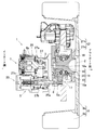
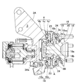
- the steering function-equipped hub unit 1 includes a hub unit body 2, a unit support member 3, a rolling bearing 4 that is a rotation-allowing support component, and a steering actuator 5.
- the unit support member 3 is provided integrally with a knuckle 6 that is a suspension frame part.
- the knuckle 6 in this example is fixed so as not to rotate in the steering direction, and is attached to a normal suspension device 12. Therefore, the steering of the wheel 9 of the vehicle equipped with the hub unit 1 with a steering function is determined only by the operation of the steering actuator 5.
- the hub unit 1 with a steering function is used to independently change the angles of the left and right wheels 9 in addition to the steering of the wheels 9 by a steering operation.
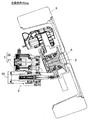
- the actuator body 7 of the steering actuator 5 is provided on the inboard side of the unit support member 3, and the hub unit body 2 is provided on the outboard side of the unit support member 3.
- the vehicle width direction outer side of the vehicle is referred to as an outboard side
- the vehicle width direction center side of the vehicle is referred to as an inboard side.
- the hub unit main body 2 and the actuator main body 7 are connected by a joint portion 8.
- the joint portion 8 is provided with a boot (not shown) for waterproofing and dustproofing.
- the joint portion 8 is provided with a reaction force sensor Sa described later.
- the hub unit main body 2 is supported by the unit support member 3 via rolling bearings 4 and 4 at two upper and lower positions so as to be rotatable around the turning axis A extending in the vertical direction. Yes.
- the turning axis A is an axis different from the rotation axis O of the wheel 9.
- the wheel 9 includes a wheel 9a and a tire 9b.
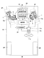
- the hub unit 1 with a steering function is provided on the knuckle 6 of the suspension device 12 (FIG. 1) and is provided on the left and right front wheels 9F and 9F which are steering wheels in the vehicle 10, respectively.
- the suspension device 12 (FIG. 1) uses, for example, a strut suspension mechanism that directly fixes the shock absorber to the knuckle 6. However, a multi-link suspension mechanism or other suspension mechanisms may be applied.
- the hub unit 1 with a steering function and the steering input portion 11a that is a steering wheel are not mechanically coupled but are electrically connected only by an electrical signal.
- the steering input unit 11a is provided with a sensor Sb that detects and outputs a rotation angle and an angular velocity by a driver's steering operation.
- the steer-by-wire system operates the steering actuators 5 and 5 based on the electric signal output from the sensor Sb, and freely steers the left and right front wheels 9F and 9F independently according to the traveling conditions of the vehicle 10. .
- a rotation angle detecting means such as a resolver for detecting the rotation angle can be adopted.
- the angular velocity is obtained by differentiating the rotation angle detected by the rotation angle detection means.
- the steer-by-wire system includes a reaction force sensor Sa that detects a reaction force from a tire, and a reaction force that is applied to the steering input unit 11a only from the reaction force detected by the reaction force sensor Sa to information necessary for the driver (steering reaction force). And an actuator Ha.
- the reaction force sensor Sa is a sensor for detecting a reaction force acting on the joint portion 8, and for example, a load cell or a load sensor is applied.
- the reaction force sensor Sa detects the axial force applied to the linear motion output unit 25a by converting the linear motion output unit 25a of the steering actuator 5 back and forth, and converts it into an electrical signal.
- the relationship between the electrical signal obtained by the reaction force sensor Sa and the steering reaction force generated by the reaction force actuator Ha is determined by, for example, a map or an arithmetic expression. Therefore, according to this steer-by-wire system, it is possible to realize a steering feeling according to the vehicle situation.
- the steering actuators 5 and 5 may be operated according to commands from an unillustrated automatic driving device or driving support device.
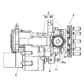
- the hub unit main body 2 includes a hub bearing 15 for supporting the wheels 9, an outer ring 16, and an arm portion 17 (FIG. 3) that is a steering force receiving portion described later.
- the hub bearing 15 includes an inner ring 18, an outer ring 19, and rolling elements 20 such as balls interposed between the inner and outer rings 18 and 19, and serves to connect the vehicle body side member and the wheel 9.
- the hub bearing 15 is an angular ball bearing in which the outer ring 19 is a fixed ring, the inner ring 18 is a rotating ring, and the rolling elements 20 are in a double row.
- the inner ring 18 includes a hub ring portion 18a having a hub flange 18aa and constituting a race surface on the outboard side, and an inner ring portion 18b constituting a race surface on the inboard side.
- the wheel 9a of the wheel 9 is bolted to the hub flange 18aa so as to overlap the brake rotor 21a.
- the inner ring 18 rotates around the rotation axis O.
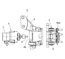
- the outer ring 16 has an annular portion 16a fitted to the outer peripheral surface of the outer ring 19, and trunnion shaft-like mounting shaft portions 16b and 16b provided so as to protrude vertically from the outer periphery of the annular portion 16a.
- Each attachment shaft portion 16 b is provided coaxially with the turning shaft center A.
- the brake 21 has a brake rotor 21a and a brake caliper 21b.
- the brake caliper 21b is mounted on two upper and lower brake caliper mounting portions 22 (FIG. 5) formed integrally with the outer ring 19 so as to project into an arm shape.
- a tapered roller bearing is applied as the rolling bearing 4 that is each rotation-supporting support component.
- a tapered roller bearing is applied as the rolling bearing (rotation permitting support component) 4.
- the rolling bearing 4 includes an inner ring 4a fitted to the outer periphery of the mounting shaft portion 16b, an outer ring 4b fitted to the unit support member 3, and a plurality of rolling elements 4c interposed between the inner and outer rings 4a and 4b. .
- the unit support member 3 includes a unit support member main body 3A and a unit support member combined body 3B.
- a substantially ring-shaped unit support member assembly 3B is detachably fixed to the end of the unit support member main body 3A on the outboard side.
- Partial concave spherical fitting hole forming portions 3a are respectively formed on the upper and lower portions of the side surface of the inboard side of the unit support member assembly 3B.
- partial concave spherical fitting hole forming portions 3Aa are respectively formed on the upper and lower portions of the outboard side end of the unit support member main body 3A.
- the unit support member combination 3B is fixed to the outboard side end of the unit support member main body 3A.
- the fitting hole forming portions 3a and 3Aa are combined with each other to form a fitting hole that is connected to the entire circumference.
- the outer ring 4b is fitted in the fitting hole.
- the unit support member 3 is indicated by a one-dot chain line.
- each mounting shaft portion 16b of the outer ring 16 is formed with a female screw portion extending in the radial direction, and is provided with a bolt 23 that is screwed into the female screw portion.
- a disc-shaped pressing member 24 is interposed on the end surface of the inner ring 4a, and a preload is applied to each rolling bearing 4 by applying a pressing force to the end surface of the inner ring 4a by a bolt 23 screwed into the female screw portion. Yes.
- the rigidity of each rolling bearing 4 can be improved. Even when the weight of the vehicle acts on the hub unit, the initial preload is set so as not to be released. For this reason, this hub unit with a steering function can ensure the rigidity as a steering device.
- the rolling bearing 4 is not limited to a tapered roller bearing, and an angular ball bearing can be used depending on the use conditions such as the maximum load. Even in that case, a preload can be applied in the same manner as described above.
- the arm portion 17 is a portion serving as an action point for applying a steering force to the outer ring 19 of the hub bearing 15, and projects integrally with a part of the outer periphery of the outer ring 19.
- the arm portion 17 is rotatably connected to the linear motion output portion 25 a of the steering actuator 5 via the joint portion 8.
- the hub unit main body 2 rotates around the turning axis A (FIG. 1), that is, is steered.
- FIGS. 8 and 9 show the state of the right wheel 9 when turning left and when turning right, respectively.
- the steering angle of the wheel 9 is changed by moving a linear motion mechanism 25 of the steering actuator 5 described later by a motor 26.
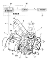
- the steering actuator 5 includes an actuator body 7 that rotates the hub unit body 2 about the turning axis A (FIG. 1). As shown in FIG. 2, the actuator body 7 converts a motor 26, a speed reducer 27 that decelerates the rotation of the motor 26, and a forward / reverse rotation output of the speed reducer 27 into a reciprocating linear motion of the linear motion output unit 25a. And a linear motion mechanism 25.
- the motor 26 is, for example, a permanent magnet type synchronous motor, but may be a DC motor or an induction motor.
- the reducer 27 may be omitted.
- the reduction gear 27 can use a wrapping transmission mechanism such as a belt transmission mechanism or a gear train, and a belt transmission mechanism is used in the example of FIG.
- the reducer 27 includes a drive pulley 27a, a driven pulley 27b, and a belt 27c.
- a drive pulley 27 a is coupled to the motor shaft of the motor 26, and a driven pulley 27 b is provided in the linear motion mechanism 25.
- the driven pulley 27b is disposed in parallel to the motor shaft.
- the driving force of the motor 26 is transmitted from the drive pulley 27a to the driven pulley 27b via the belt 27c.
- the drive pulley 27a, the driven pulley 27b, and the belt 27c constitute a winding-type speed reducer 27.
- a feed screw mechanism such as a slide screw or a ball screw, a rack and pinion mechanism, or the like can be used.
- a feed screw mechanism using a trapezoidal screw slide screw is used. Since the linear motion mechanism 25 includes a feed screw mechanism that uses a sliding screw of the trapezoidal screw, the effect of preventing reverse input from the tire 9b can be enhanced.
- the actuator body 7 including the motor 26, the speed reducer 27, and the linear motion mechanism 25 is assembled as a semi-assembly and is detachably attached to the case 6b with bolts or the like. A mechanism that directly transmits the driving force of the motor 26 to the linear motion mechanism 25 without using a reduction gear is also possible.
- the case 6b is integrally formed with the unit support member main body 3A as a part of the unit support member 3.
- the case 6 b is formed in a bottomed cylindrical shape, and is provided with a motor housing portion that supports the motor 26 and a linear motion mechanism housing portion that supports the linear motion mechanism 25.
- a fitting hole for supporting the motor 26 at a predetermined position in the case is formed in the motor housing portion.
- the linear motion mechanism accommodating portion is formed with a fitting hole for supporting the linear motion mechanism 25 at a predetermined position in the case, a through hole for allowing the linear motion output portion 25a to advance and retreat.
- the unit support member main body 3A includes the case 6b and a shock absorber mounting portion 6c that is a mounting portion of the shock absorber.
- the shock absorber mounting portion 6c is also formed integrally with the unit support member main body 3A.
- a shock absorber mounting portion 6c is formed on the upper portion of the outer surface portion of the unit support member main body 3A so as to protrude.
- the hub unit body 2 including the hub bearing 15 that supports the wheel 9 is freely rotated around the turning axis A by driving the steering actuator 5. Can do. For this reason, steering can be performed independently for each wheel, and the toe angle of the wheel 9 can be arbitrarily changed according to the traveling state of the vehicle 10. Since the hub unit body 2 is supported by the unit support member 3 via the rolling bearings 4 and 4 to which preload is applied, the hub unit 1 with a steering function can ensure rigidity as a steering device.
- this configuration When this configuration is applied to the front wheel 9F, the wheel 9 which is the front wheel 9F is steered by the steering operation of the driver. Steering can be performed independently for each wheel.
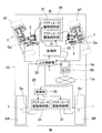
- this configuration can be applied to the rear wheel 9R (FIG. 11).
- the steering function of the rear wheel 9R reduces the turning radius of the vehicle and reduces the turning performance. It becomes possible to improve. Since it is not necessary to ensure a large steering angle of the rear wheel 9R (FIG. 11), the steering actuator can be reduced in size.
- the hub actuator 2 can be freely rotated around the turning axis A by the steering actuator 5. You can freely change the left and right independently. Since the steering mechanism is provided in the hub unit 1, there is a margin in the space of the chassis front part. Furthermore, since the steering actuator 5 is arranged in the hub unit 1, it is not necessary to arrange the steering device in the vehicle width direction, and the space in the vehicle can be used widely.
- the rudder angle difference between the left and right wheels 9 and 9 when turning, by changing the rudder angle difference between the left and right wheels 9 and 9 according to information (vehicle speed, steering wheel angle, lateral force, etc.) obtained from the sensor of the vehicle 10, for example, turning at high speeds. It is also possible to change the steering geometry during traveling, such as parallel geometry for A, and Ackermann geometry for turning at low speeds. Thus, since the steering angle of the wheel 9 can be freely changed during traveling, it is possible to improve the motion performance of the vehicle 10 and to travel with high stability and reliability.
- the turning radius of the vehicle 10 in turning traveling can be reduced and the turning performance can be improved. Furthermore, during straight running, it is possible to make adjustments such as ensuring running stability without reducing fuel consumption by adjusting the toe angle in accordance with each scene.
- the steering input unit 11a such as a steering wheel and the wheel 9 are not mechanically connected, vibration unpleasant to the driver can be cut off when traveling on a gravel road or a cobblestone. Only information necessary for the driver can be transmitted to the driver from, for example, the reaction force actuator Ha of the steering input unit 11a.
- the steering system includes a hub unit 1 with a steering function and a control device 29 that controls the steering actuator 5 of the hub unit 1 with a steering function.
- the control device 29 includes a control unit 30 and an actuator drive control unit 31.
- the driver operates the steering angle of the wheel with the steering wheel, and the upper control unit 32 outputs a steering angle command signal e for the left and right wheels calculated in consideration of the vehicle condition and the like according to the steering wheel operating angle.
- the control unit 30 outputs a current command signal f corresponding to the steering angle command signal e given from the host control unit 32.
- the upper control unit 32 is an upper control means of the control unit 30, and an electric control unit (Vehicle Control Unit, abbreviated as VCU) for controlling the entire vehicle is applied as the upper control unit 32, for example.
- VCU Electric Control Unit
- the actuator drive control unit 31 drives and controls the steering actuator 5 by outputting a drive current g corresponding to the current command signal f input from the control unit 30.
- the actuator drive control unit 31 controls the power supplied to the coil of the motor 26.
- the actuator drive control unit 31 configures, for example, a half bridge circuit using a switch element (not shown), and performs PWM control for determining a motor applied voltage based on the ON-OFF duty ratio of the switch element.
- the angle of the wheel can be changed by changing the angle of the hub unit main body 2 with respect to the unit support member 3. Even when running straight, the amount of toe angle can be adjusted to suit each scene. Therefore, it is possible to improve athletic performance and fuel consumption.
- the steering function-equipped hub unit 1 may be mounted on the left and right front wheels 9F, 9F and the left and right rear wheels 9R, 9R.
- the toe angle adjustment during traveling is effective, and the minimum turning radius during low-speed traveling can be reduced.
- SYMBOLS 1 Hub unit with a steering function
- 2 ... Hub unit main body, 3 ... Unit support member, 4 ... Rolling bearing (rotation allowance support component), 5 ... Steering actuator, 6 ... Knuckle (suspension frame component), 9 ... Wheel , 9F ... front wheel, 9R ... rear wheel, 10 ... vehicle, 11a ... steering input unit, 12 ... suspension device, 15 ... hub bearing, 29 ... control device, 30 ... control unit, 31 ... actuator drive control unit
Landscapes
- Engineering & Computer Science (AREA)
- Mechanical Engineering (AREA)
- General Engineering & Computer Science (AREA)
- Chemical & Material Sciences (AREA)
- Combustion & Propulsion (AREA)
- Transportation (AREA)
- Physics & Mathematics (AREA)
- Mathematical Physics (AREA)
- Power Steering Mechanism (AREA)
- Steering-Linkage Mechanisms And Four-Wheel Steering (AREA)
- Steering Control In Accordance With Driving Conditions (AREA)
Priority Applications (3)
| Application Number | Priority Date | Filing Date | Title |
|---|---|---|---|
| EP19775319.7A EP3778355A4 (de) | 2018-03-27 | 2019-03-26 | Nabeneinheit mit lenkfunktion, lenksystem und fahrzeug |
| CN201980022347.7A CN111918810B (zh) | 2018-03-27 | 2019-03-26 | 线控系统和车辆 |
| US17/032,467 US11731693B2 (en) | 2018-03-27 | 2020-09-25 | Hub unit with steering function, steering system, and vehicle |
Applications Claiming Priority (2)
| Application Number | Priority Date | Filing Date | Title |
|---|---|---|---|
| JP2018-059174 | 2018-03-27 | ||
| JP2018059174A JP7244994B2 (ja) | 2018-03-27 | 2018-03-27 | 操舵機能付ハブユニット、操舵システム、および操舵機能付ハブユニットを備えた車両 |
Related Child Applications (1)
| Application Number | Title | Priority Date | Filing Date |
|---|---|---|---|
| US17/032,467 Continuation US11731693B2 (en) | 2018-03-27 | 2020-09-25 | Hub unit with steering function, steering system, and vehicle |
Publications (1)
| Publication Number | Publication Date |
|---|---|
| WO2019189103A1 true WO2019189103A1 (ja) | 2019-10-03 |
Family
ID=68061665
Family Applications (1)
| Application Number | Title | Priority Date | Filing Date |
|---|---|---|---|
| PCT/JP2019/012728 Ceased WO2019189103A1 (ja) | 2018-03-27 | 2019-03-26 | 操舵機能付ハブユニット、操舵システムおよび車両 |
Country Status (5)
| Country | Link |
|---|---|
| US (1) | US11731693B2 (de) |
| EP (1) | EP3778355A4 (de) |
| JP (1) | JP7244994B2 (de) |
| CN (1) | CN111918810B (de) |
| WO (1) | WO2019189103A1 (de) |
Cited By (4)
| Publication number | Priority date | Publication date | Assignee | Title |
|---|---|---|---|---|
| CN111806555A (zh) * | 2020-06-03 | 2020-10-23 | 中国北方车辆研究所 | 推拉缸置于单纵臂悬架单纵臂上的独立转向系统 |
| US11772487B2 (en) | 2018-10-04 | 2023-10-03 | Ronald A. Holland | Vehicle rear drive axle |
| CN117207770A (zh) * | 2022-06-03 | 2023-12-12 | 现代摩比斯株式会社 | 用于车辆的角模块装置 |
| US20240286679A1 (en) * | 2021-06-28 | 2024-08-29 | Robert Bosch Gmbh | Method for Adjusting a Track of at least one Vehicle Wheel |
Families Citing this family (5)
| Publication number | Priority date | Publication date | Assignee | Title |
|---|---|---|---|---|
| JP7138526B2 (ja) * | 2018-09-28 | 2022-09-16 | Ntn株式会社 | 操舵機能付ハブユニットおよびこれを備えた車両 |
| CN111806553A (zh) * | 2020-06-03 | 2020-10-23 | 中国北方车辆研究所 | 转向电机置于单纵臂悬架单纵臂上的独立转向系统 |
| CN112172914B (zh) * | 2020-12-03 | 2021-02-12 | 山东悍沃农业装备有限公司 | 一种用于电动拖拉机的动力转向控制机构及其使用方法 |
| JP2022114979A (ja) * | 2021-01-27 | 2022-08-08 | Ntn株式会社 | 操舵機能付ハブユニット、操舵システムおよび車両 |
| JP7846548B2 (ja) * | 2022-03-23 | 2026-04-15 | 株式会社Subaru | 車両の操舵装置 |
Citations (9)
| Publication number | Priority date | Publication date | Assignee | Title |
|---|---|---|---|---|
| JPS5615094B2 (de) | 1973-08-27 | 1981-04-08 | ||
| JP2005349845A (ja) | 2004-06-08 | 2005-12-22 | Toyoda Mach Works Ltd | ステアバイワイヤシステム |
| JP2007062628A (ja) * | 2005-09-01 | 2007-03-15 | Ntn Corp | 懸架装置の支持構造 |
| JP4230947B2 (ja) | 2004-03-22 | 2009-02-25 | 株式会社日立製作所 | 車両制御装置 |
| JP3158339U (ja) * | 2010-01-14 | 2010-03-25 | 株式会社キャロッセ | キングピンベアリングの与圧調整機構 |
| DE102012206337A1 (de) | 2012-04-18 | 2013-10-24 | Schaeffler Technologies AG & Co. KG | Gelenkige Lagerung eines Radlagers zur Sturz- und/oder Spurverstellung |
| JP2014061744A (ja) * | 2012-09-20 | 2014-04-10 | Jtekt Corp | 転舵装置および車両 |
| JP5615094B2 (ja) * | 2010-08-25 | 2014-10-29 | Ntn株式会社 | ステアバイワイヤ式操舵装置 |
| JP2018024284A (ja) * | 2016-08-08 | 2018-02-15 | 株式会社豊田中央研究所 | ステアバイワイヤ式操舵装置 |
Family Cites Families (33)
| Publication number | Priority date | Publication date | Assignee | Title |
|---|---|---|---|---|
| DE1806566C3 (de) * | 1968-11-02 | 1978-07-13 | Dr.Ing.H.C. F. Porsche Ag, 7000 Stuttgart | Befestigungsvorrichtung für ein Rad an einer Nabe bei Kraftfahrzeugen |
| JP3158339B2 (ja) | 1995-11-14 | 2001-04-23 | 株式会社ユニシアジェックス | 内燃機関の排気還流装置の故障診断装置 |
| US6364426B1 (en) * | 1998-08-05 | 2002-04-02 | Kelsey-Hayes Company | Vehicle wheel hub and bearing unit assembly and method for producing same |
| JP3934367B2 (ja) * | 2001-07-03 | 2007-06-20 | アルプス電気株式会社 | バイワイヤ方式のステアリング装置 |
| US6678596B2 (en) * | 2002-05-21 | 2004-01-13 | Visteon Global Technologies, Inc. | Generating steering feel for steer-by-wire systems |
| JP4292054B2 (ja) | 2003-11-06 | 2009-07-08 | 本田技研工業株式会社 | 車両用操舵装置 |
| JP4806930B2 (ja) | 2004-12-22 | 2011-11-02 | 日産自動車株式会社 | 車両用操舵装置 |
| JP4724075B2 (ja) * | 2006-08-29 | 2011-07-13 | 本田技研工業株式会社 | ホイール回転装置 |
| JP2008168744A (ja) | 2007-01-10 | 2008-07-24 | Fuji Heavy Ind Ltd | 左右独立操舵装置 |
| EP1975041B1 (de) * | 2007-03-27 | 2013-10-16 | Honda Motor Co., Ltd. | Lenksystem |
| JP5226999B2 (ja) | 2007-11-02 | 2013-07-03 | 富士重工業株式会社 | 車両の操舵装置 |
| DE102008003646A1 (de) * | 2008-01-09 | 2009-07-16 | GM Global Technology Operations, Inc., Detroit | Radnabengelenkeinheit für ein Fahrzeug |
| JP2009226972A (ja) | 2008-03-19 | 2009-10-08 | Fuji Heavy Ind Ltd | ジオメトリ可変装置 |
| JP5386103B2 (ja) * | 2008-04-17 | 2014-01-15 | ニチユ三菱フォークリフト株式会社 | 車両のステアリング制御装置 |
| JP2010179678A (ja) | 2009-02-03 | 2010-08-19 | Honda Motor Co Ltd | 路面摩擦係数推定装置 |
| JP5332982B2 (ja) | 2009-07-08 | 2013-11-06 | 日産自動車株式会社 | 車両用制御装置 |
| EP2554408B1 (de) | 2010-03-31 | 2017-08-09 | Equos Research Co., Ltd. | Vorrichtung zur einstellung eines krümmungswinkels |
| JP5697966B2 (ja) * | 2010-12-20 | 2015-04-08 | Ntn株式会社 | ステアバイワイヤの操舵反力制御装置 |
| CN102069843B (zh) * | 2011-01-05 | 2012-11-07 | 吉林大学 | 线控车轮独立转向执行机构及车轮总成 |
| CN203094172U (zh) * | 2012-12-24 | 2013-07-31 | 中国科学院深圳先进技术研究院 | 一种独立转向与驱动电动汽车的线控转向装置及其悬架系统 |
| JP6050156B2 (ja) | 2013-03-11 | 2016-12-21 | 川崎重工業株式会社 | 案内軌条式車両用案内装置、及び案内軌条式車両 |
| JP6351944B2 (ja) | 2013-09-26 | 2018-07-04 | Ntn株式会社 | ステアリング装置 |
| JP6297306B2 (ja) | 2013-11-14 | 2018-03-20 | Ntn株式会社 | 車両 |
| JP6452944B2 (ja) | 2013-11-18 | 2019-01-16 | Ntn株式会社 | ステアリング装置 |
| CN103895697B (zh) * | 2014-04-16 | 2016-06-08 | 中国科学院深圳先进技术研究院 | 一种电动汽车四轮独立转向底盘系统及其线控转向机构 |
| CN104908809A (zh) | 2015-06-11 | 2015-09-16 | 杭州伯坦科技工程有限公司 | 一种车轮独立转向系统 |
| US10053148B2 (en) | 2015-06-15 | 2018-08-21 | GM Global Technology Operations LLC | Toe optimization system for a vehicle |
| JP6591296B2 (ja) | 2016-01-18 | 2019-10-16 | Ntn株式会社 | 車輪軸受装置 |
| CN106335542B (zh) * | 2016-09-30 | 2018-08-03 | 南京航空航天大学 | 四轮独立转向机构及工作方法 |
| US10293636B2 (en) * | 2017-05-03 | 2019-05-21 | Arvinmeritor Technology, Llc | Wheel end assembly having a deflector |
| JP6909071B2 (ja) * | 2017-06-23 | 2021-07-28 | Ntn株式会社 | 補助転舵機能付ハブユニットおよび車両 |
| JP2019006226A (ja) * | 2017-06-23 | 2019-01-17 | Ntn株式会社 | 補助転舵機能付ハブユニットおよび車両 |
| JP7202930B2 (ja) * | 2018-03-20 | 2023-01-12 | Ntn株式会社 | ステアリングシステムおよびそれを備えた車両 |
-
2018
- 2018-03-27 JP JP2018059174A patent/JP7244994B2/ja active Active
-
2019
- 2019-03-26 CN CN201980022347.7A patent/CN111918810B/zh active Active
- 2019-03-26 EP EP19775319.7A patent/EP3778355A4/de active Pending
- 2019-03-26 WO PCT/JP2019/012728 patent/WO2019189103A1/ja not_active Ceased
-
2020
- 2020-09-25 US US17/032,467 patent/US11731693B2/en active Active
Patent Citations (9)
| Publication number | Priority date | Publication date | Assignee | Title |
|---|---|---|---|---|
| JPS5615094B2 (de) | 1973-08-27 | 1981-04-08 | ||
| JP4230947B2 (ja) | 2004-03-22 | 2009-02-25 | 株式会社日立製作所 | 車両制御装置 |
| JP2005349845A (ja) | 2004-06-08 | 2005-12-22 | Toyoda Mach Works Ltd | ステアバイワイヤシステム |
| JP2007062628A (ja) * | 2005-09-01 | 2007-03-15 | Ntn Corp | 懸架装置の支持構造 |
| JP3158339U (ja) * | 2010-01-14 | 2010-03-25 | 株式会社キャロッセ | キングピンベアリングの与圧調整機構 |
| JP5615094B2 (ja) * | 2010-08-25 | 2014-10-29 | Ntn株式会社 | ステアバイワイヤ式操舵装置 |
| DE102012206337A1 (de) | 2012-04-18 | 2013-10-24 | Schaeffler Technologies AG & Co. KG | Gelenkige Lagerung eines Radlagers zur Sturz- und/oder Spurverstellung |
| JP2014061744A (ja) * | 2012-09-20 | 2014-04-10 | Jtekt Corp | 転舵装置および車両 |
| JP2018024284A (ja) * | 2016-08-08 | 2018-02-15 | 株式会社豊田中央研究所 | ステアバイワイヤ式操舵装置 |
Cited By (6)
| Publication number | Priority date | Publication date | Assignee | Title |
|---|---|---|---|---|
| US11772487B2 (en) | 2018-10-04 | 2023-10-03 | Ronald A. Holland | Vehicle rear drive axle |
| CN111806555A (zh) * | 2020-06-03 | 2020-10-23 | 中国北方车辆研究所 | 推拉缸置于单纵臂悬架单纵臂上的独立转向系统 |
| CN111806555B (zh) * | 2020-06-03 | 2022-03-25 | 中国北方车辆研究所 | 推拉缸置于单纵臂悬架单纵臂上的独立转向系统 |
| US20240286679A1 (en) * | 2021-06-28 | 2024-08-29 | Robert Bosch Gmbh | Method for Adjusting a Track of at least one Vehicle Wheel |
| US12195086B2 (en) * | 2021-06-28 | 2025-01-14 | Robert Bosch Gmbh | Method for adjusting a track of at least one vehicle wheel |
| CN117207770A (zh) * | 2022-06-03 | 2023-12-12 | 现代摩比斯株式会社 | 用于车辆的角模块装置 |
Also Published As
| Publication number | Publication date |
|---|---|
| CN111918810A (zh) | 2020-11-10 |
| JP2019171912A (ja) | 2019-10-10 |
| EP3778355A1 (de) | 2021-02-17 |
| CN111918810B (zh) | 2022-09-27 |
| EP3778355A4 (de) | 2021-12-22 |
| US11731693B2 (en) | 2023-08-22 |
| JP7244994B2 (ja) | 2023-03-23 |
| US20210009199A1 (en) | 2021-01-14 |
Similar Documents
| Publication | Publication Date | Title |
|---|---|---|
| JP7244994B2 (ja) | 操舵機能付ハブユニット、操舵システム、および操舵機能付ハブユニットを備えた車両 | |
| JP6567633B2 (ja) | 転舵機能付ハブユニットおよびこれを備えた車両 | |
| EP3858709B1 (de) | Nabeneinheit mit lenkfunktion und mit nabeneinheit ausgestattetes fahrzeug | |
| JP7037315B2 (ja) | 転舵機能付ハブユニットおよびこれを備えた車両 | |
| WO2021106894A1 (ja) | 操舵機能付ハブユニットおよびこれを備えた車両 | |
| WO2018235891A1 (ja) | 補助転舵機能付ハブユニットおよび車両 | |
| WO2019189100A1 (ja) | 転舵機能付ハブユニットおよびこれを備えた車両 | |
| JP7060984B2 (ja) | 転舵機能付ハブユニットおよびこれを備えた車両 | |
| JP7177681B2 (ja) | 操舵機能付ハブユニットおよびこれを備えた車両 | |
| JP2020097280A (ja) | 操舵機能付ハブユニットおよび操舵システム | |
| WO2019189102A1 (ja) | 操舵機能付ハブユニットおよびこれを備えた車両 | |
| JP7049864B2 (ja) | 転舵機能付きハブユニット、転舵システム、および転舵機能付きハブユニットを備えた車両 | |
| JP7296332B2 (ja) | 操舵機能付ハブユニットおよびこれを備えた車両 | |
| JP7450376B2 (ja) | 操舵機能付ハブユニットおよびこれを備えた車両 | |
| JP6720393B2 (ja) | 転舵軸付ハブベアリングおよび転舵機能付ハブユニット | |
| JP6899466B2 (ja) | 転舵軸付ハブベアリングおよびこれを備えた車両 | |
| JP2023047456A (ja) | 操舵機能付ハブユニット、操舵システムおよび車両 | |
| JP2020097256A (ja) | 操舵機能付ハブユニットおよび操舵システム並びにこれを備えた車両 | |
| JP6899464B2 (ja) | 転舵軸付ハブベアリングおよびこれを備えた車両 | |
| JP7245077B2 (ja) | 操舵機能付ハブユニットおよびこれを備えた車両 | |
| WO2022163568A1 (ja) | 操舵機能付ハブユニット、操舵システムおよび車両 | |
| JP2025035225A (ja) | 操舵システムおよび車両 | |
| JP2024110813A (ja) | 操舵システムおよびそれを備えた車両 | |
| JP2021098395A (ja) | 操舵機能付ハブユニットおよびこれを備えた車両 | |
| JP2020100401A (ja) | 後輪用操舵システムおよびこれを備えた車両 |
Legal Events
| Date | Code | Title | Description |
|---|---|---|---|
| 121 | Ep: the epo has been informed by wipo that ep was designated in this application |
Ref document number: 19775319 Country of ref document: EP Kind code of ref document: A1 |
|
| NENP | Non-entry into the national phase |
Ref country code: DE |
|
| ENP | Entry into the national phase |
Ref document number: 2019775319 Country of ref document: EP Effective date: 20201027 |